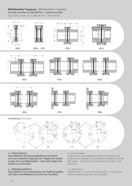
BSD Modulflex ® Kupplung | BSD Modulflex ® Coupling Typ 920x bis 928x bis 280 000 Nm | Ausführung Stahl Type 920x to 928x up to 280 000 Nm | Steel Version 920x 920x-...-050 921x 922x 923x 924x 925x 926x 927x 928x Lochteilung | Hole pitch A B C D x = Abdrücklöcher: Gewindelöcher als Demontagehilfe bei montierter und axial arretierter Kupplung. Nur möglich bei Ausführungen mit 2 Lamellenpaketen - also nicht möglich bei Typ 921x und Typ 922x. x 1 = Befestigungslöcher: Gewindelöcher zum Anschrauben der Verbindungsteile - z.B. Nabe und Mittelstück (Typ 921x bis Typ 926x). x = pull-off-holes: Tapped holes as disassembly aid for assembled <strong>and</strong> axially fixed coupling. Only possible for designs with two disc packs - therefore, not possible for type 921 x <strong>and</strong> type 922x. x 1 = fixing holes: Tapped holes to screw connecting parts - e.g. hub <strong>and</strong> center member (type 921x to type 926x). 14
BSD Modulflex ® Kupplung | BSD Modulflex ® Coupling Typ 920x bis 928x bis 280 000 Nm | Ausführung Stahl Type 920x to 928x up to 280 000 Nm | Steel Version Techn. Daten Technical Data Nenndrehmoment Nominal Torque Maximaldrehmoment Maximum Torque Axiale Nachgiebigkeit (1) Axial Misalignment Radiale Nachgiebigkeit (2) Radial Misalignment Radiale Nachgiebigkeit (3) Radial Misalignment Winklige Nachgiebigkeit (1) Angular Misalignment Größe Size 2,8 4,5 6,4 11 17 28 45 64 110 170 280 450 640 1100 1700 2800 T KN Nm 280 450 640 1 100 1 700 2 800 4 500 6 400 11 000 17 000 28 000 45 000 64 000 110 000 170 000 280 000 T Kmax Nm 500 800 1 250 2 000 3 150 5 000 8 000 12 500 20 000 31 500 50 000 80 000 125 000 193 000 300 000 500 000 Δ Ka max mm 1 1,2 1,3 1,4 1,5 1,6 2 2,1 2,5 2,9 3,2 3,6 4,1 4,6 4,8 5,0 Δ Kr max mm 0,9 1 1,2 1,2 1,2 1,4 1,6 2,6 2,8 3,3 3,5 4,2 4,4 4,9 5,4 - Δ Kr max mm 0,38 0,42 0,41 0,42 0,42 0,45 0,58 0,65 0,76 0,86 1 1,18 1,33 1,65 2 - Δ Kw max ° 0,75 Drehfederwert x 10 6 (1) Torsional Spring Rate x 10 6 C Tdyn Nm/rad 0,11 0,16 0,41 0,75 1,3 2,19 3,53 4,63 6,52 11,91 17,18 29,09 39,48 59,24 74,61 121,91 Maximale Drehzahl (4) Maximum Speed n max min -1 44 000 39 000 31 400 27 100 23 200 21 000 18 400 15 600 14 500 12 800 11 300 10 100 8 100 7 700 6 900 5 500 Massenträg-heitsmoment 920x 0,0006 0,0013 0,0029 0,0073 0,0089 0,0180 0,044 0,076 0,138 0,275 0,556 1,04 1,83 3,83 6,48 8,549 (5) 921x J kgm² 0,0012 0,0025 0,0067 0,02 0,025 0,0460 0,121 0,205 0,399 0,724 1,58 2,63 4,65 9,81 16,2 - Moment of Inertia 923x 0,0021 0,0044 0,012 0,033 0,041 0,0760 0,196 0,339 0,637 1,2 2,51 4,41 7,64 15,9 26,3 - Gewicht Weight (5) Abmessungen in mm Dimensions in mm Durchmesser Diameters Längen Lengths 920x 0,7 1 1,6 2,5 2,6 3,9 7 9,9 14,1 21 33 48 68 110 157 - 921x m kg 1,6 2,4 4,1 8 8,7 12,1 23,3 31,4 49 65 110 145 200 324 442 - 923x 2,7 4 6,8 12,4 13,2 18,9 35,8 49 74 104 168 235 319 512 702 - A j6 75 88 110 139 146 170 200 222 248 285 325 366 408 465 504 590 B 39 47 55 68 82 90 102 118 135 152 162 195 215 250 275 290 C 64 77 99 127 134 154 182 200 224 258 295 330 369 420 458 510 D H7 max 35 44 55 70 80 90 105 120 135 160 180 200 240 270 300 - E 48 60 75 100 110 120 145 162 188 210 250 268 308 358 395 - F 79 92 114 143 150 174 205 227 252 293 334 375 416 475 516 - G 64 77 86 112 122 135 160 176 206 228 268 288 328 384 422 - I 12 13 12 12,2 12,5 13 17 19,1 22,8 25,5 30 35,7 40,5 51 64 - K 29,5 32,5 31 32 32,5 34,5 44 50 58 65,5 76,5 90 101,5 126 153 185 L 45 50 55 70 75 85 110 120 140 160 180 200 240 270 300 - S 2 101 107 125 126 126 149 170 253 272 324 356 414 442 505 568 - auf Anfrage / on dem<strong>and</strong> S 5 Gewinde Thread Figur | Figure Lochteilung | Hole pitch M M8 M8 M8 M8 M8 M10 M12 M16 M16 M20 M24 M27 M30 M33 M33 M42 N 8 8 6 6 6 8 8 8 10 10 10 12 12 16 16 16 A A B B C C C D D D D D D D D D (1) Axiale und winklige Nachgiebigkeiten und Drehfederwerte beziehen sich auf ein flexibles Element. Axial <strong>and</strong> angular misalignments <strong>and</strong> torsional spring rates refer to one flexible element. (2) Radiale Nachgiebigkeiten gelten nur für Typ 923x und 924x. Radial misalignements only refer to type 923x <strong>and</strong> 924x. (3) Radiale Nachgiebigkeiten gelten nur für Typ 920x-...-050. Radial misalignements only refer to type 920x-...-050. (4) Hohe Drehzahlen können dynamisches Wuchten erfordern. Dynamic balancing might be required for high speeds. (5) Bei maximaler Bohrung. At maximum bore. • Axialfederwerte gemäß separater Tabelle und Diagramm. Axial spring rates acc. to separate table <strong>and</strong> graph. Bestellbeispiel / Ordering Example Typ Type Bohrung Bore dia. Ø mm Nut Keyway DIN 6885/1 Bohrung Bore dia. Ø mm Nut Keyway DIN 6885/1 Maß S5 (nur 986x) Dim. S5 (only 986x) mm Betriebsdrehzahl Operating Speed min -1 9231-2,8-000 D = 22 H7 6 x 2,8 D = 32 H7 10 x 3,3 - 3 000 (> 30 m/s) Wuchten ISO 1940 G = 2,5 erforderlich Balancing acc. to ISO 1940 G = 2,5 required Typ / Type: 9231; 1 = allg. Industrieanwendung / for general industrial applications, 4 = Marine, 6 = Prüfst<strong>and</strong> / test benches Größe / Size: 2,8 Ausführung / Version: 000 = St<strong>and</strong>ard 15