Pilot controlled pressure valve type DA - Hydropa GmbH & Cie. KG
Pilot controlled pressure valve type DA - Hydropa GmbH & Cie. KG
Pilot controlled pressure valve type DA - Hydropa GmbH & Cie. KG

Sie wollen auch ein ePaper? Erhöhen Sie die Reichweite Ihrer Titel.
YUMPU macht aus Druck-PDFs automatisch weboptimierte ePaper, die Google liebt.
H<br />
Druckventile<br />
R<br />
<strong>DA</strong>S ZEICHEN DER HYDROPA GRUPPE<br />
Pressure <strong>valve</strong>s<br />
R<br />
4.41/D/E<br />
09/10
2<br />
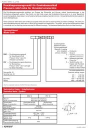
Druckbegrenzungsventil für Gewindeanschluß<br />
Pressure relief <strong>valve</strong> for threaded connection<br />
Die Druckbegrenzungsventile gehören zur Gruppe der Sitzventile und können mittels Verschraubungen in die<br />
Rohrleitung eingebaut werden. Das Ventil und die Feder sowie die Einstelleinrichtung sind so in einer Baueinheit<br />
zusammengefasst, dass diese in verschiedene Gehäuse eingebaut werden können. Der gehärtete Stahlkolben gleitet in<br />
einem Stahlgehäuse.<br />
These <strong>pressure</strong> relief <strong>valve</strong>s are working as poppet <strong>valve</strong>s and are for pipe mounting by means of fittings. The <strong>valve</strong> is a<br />
direct operated <strong>pressure</strong> relief <strong>valve</strong>. It has a spring-loaded cone seat piston. The piston, spring and adjustment are fitted<br />
in a modular unit, so that they can be mounted in different housings. The hardened steel piston works in a steel housing.<br />
Typenschlüssel<br />
Model Code<br />
DBG =<br />
PAT =<br />
Druckbegrenzungsventil<br />
für Gewindeanschluß<br />
Pressure relief <strong>valve</strong> for<br />
threaded connection<br />
Druckbegrenzungsventilpatrone<br />
für Blockeinbau<br />
Pressure relief <strong>valve</strong> cartridge<br />
for block mounting<br />
Nenngröße 18<br />
Nominal size 18<br />
Baureihe<br />
Series<br />
Viton® is a registered trademark of DuPont Performance Elastomers.<br />
Technische Daten / Schaltschema<br />
Technical data / Symbol<br />
Bauart<br />
Type of construction<br />
Anschlußart<br />
Type of connection<br />
Einbaulage<br />
Mounting position<br />
Max. Durchfluß<br />
Max. Flow<br />
Temperaturbereich<br />
Temperature range<br />
Masse Ventil<br />
Weight <strong>valve</strong><br />
Filterungsempfehlung<br />
Recommended filtration<br />
R<br />
DBG 18 PAT 18<br />
Sitzventil mit Dämpfung<br />
Seat <strong>valve</strong> with damping<br />
Gewindeanschluß<br />
Blockeinbau<br />
Thread connection<br />
Block mounting<br />
beliebig<br />
any position<br />
50 l/min<br />
-20°C bis + 70°C<br />
-20°C to + 70°C<br />
2 kg 0,6 kg<br />
25 µ<br />
D8 - *** - S<br />
Zusatzangaben:<br />
Additional option:<br />
Dichtungswerkstoff<br />
Material of sealing<br />
ohne Angaben = Perbunan<br />
without indication Buna-N<br />
V = Viton®fluoroelastomers<br />
Viton®fluoroelastomers<br />
MU = Befestigungsmutter<br />
Fixing nut<br />
S = Stellschraube und<br />
Kappe statt Handrad<br />
Set screw and cap<br />
instead of hand wheel<br />
M<br />
Druckeinstellbereiche<br />
Pressure setting ranges<br />
20 =<br />
80 =<br />
160 =<br />
280 =<br />
IN = (P)<br />
OUT = (T)<br />
3-20 bar<br />
10-80 bar<br />
60-160 bar<br />
100-280 bar
Geräteabmessungen für Druckbegrenzungsventil Typ DBG 18<br />
Dimensions for <strong>pressure</strong> relief <strong>valve</strong> <strong>type</strong> DBG 18<br />
125<br />
Geräteabmessungen für Druckbegrenzungsventilpatrone Typ PAT 18<br />
Dimensions for <strong>pressure</strong> relief <strong>valve</strong> cartridge <strong>type</strong> PAT 18<br />
max. 65<br />
55<br />
105<br />
75<br />
Druckdifferenz �p<br />
[bar]<br />
Pressure difference �p<br />
[bar]<br />
Ø19x1<br />
G 1/4<br />
M45 x 1.5<br />
Ø50<br />
180<br />
max. 195<br />
DBG 18<br />
Durchfluß Q [l/min.]<br />
Flow Q [l/min]<br />
Kontermutter SW13<br />
Counter nut CH 13<br />
20<br />
35<br />
Ø27<br />
G1/2<br />
M = Manometeranschluß<br />
M = Pressure gauge connection<br />
Ø50<br />
G1/2<br />
Ø27<br />
Erforderliche Aufnahmebohrung der Patrone<br />
Necessary installation dimensions of the cartridge<br />
Ø33<br />
max. Ø16<br />
�p-Q-Kennlinien<br />
�p-Q-Characteristic<br />
curves<br />
M32 x 1.5<br />
Ø29 H7<br />
Ø20<br />
1<br />
2x45°<br />
35<br />
3<br />
16<br />
55<br />
75 -0.1<br />
105<br />
1<br />
Druckfeder<br />
Pressure spring<br />
3-20 bar<br />
10-80 bar<br />
60-160 bar<br />
100-280 bar<br />
Ventilkegel mit<br />
Dämpfung<br />
Valve cone with<br />
damping<br />
SW 7<br />
CH 7<br />
SW 13<br />
CH 13<br />
Schnittdarstellung<br />
Sectional view<br />
Werte gemessen bei 24 mm²/s (cSt) und 323 K (50°C)<br />
Values measured at 24 mm²/s (cSt) and 323 K (50°C)<br />
M45 x 1.5<br />
Ausführung “S” mit<br />
Stellschraube und<br />
Kunststoffkappe<br />
Model “S” with set<br />
screw and<br />
plastic cap<br />
Befestigungsmutter MU<br />
Fixing nut MU<br />
10<br />
45<br />
max. 195<br />
6<br />
Handrad zur<br />
Druckeinstellung<br />
Hand wheel for<br />
<strong>pressure</strong> setting<br />
Dichtung OR 2-110<br />
(9,19 x 2,62)<br />
Seal OR 2-110<br />
(9,19 x 2,62)<br />
Dichtung OR 2-119<br />
(23,47 x 2,62)<br />
Seal OR 2-119<br />
(23,47 x 2,62)<br />
Ventilsitz<br />
Valve seat<br />
2.5<br />
Ø65<br />
R<br />
3
4<br />
Vorgesteuerte Druckventile NG 10, 25 und 32<br />
<strong>Pilot</strong> operated <strong>pressure</strong> <strong>valve</strong>s nominal size 10, 25 and 32<br />
Die Druckventile bestehen aus dem Hauptventil und dem Vorsteuerventil (<strong>Pilot</strong>-Ventil), welches ein feinfühliges Einstellen<br />
des gewünschten Betriebsdruckes selbst bei großen Ölströmen ermöglicht. Bei Druckbegrenzungsventilen ist der<br />
Aufbau eines elektromagnetischen Wegeventils sowie weiterer Vorsteuerdruckbegrenzungsventile möglich. Somit<br />
können über elektrische Schalter ein, zwei oder drei verschiedene Druckbereiche abgerufen werden.<br />
Die Druckventile eignen sich sowohl für Gewindeanschluß als auch für Plattenanschluß.<br />
Die unterschiedlichen Ausführungsmöglichkeiten sind auf den Seiten 10 bis 12 dargestellt.<br />
These <strong>pressure</strong> <strong>valve</strong>s consist of a main <strong>valve</strong> and a pilot <strong>valve</strong>. Due to this construction a sensitive adjustment of the<br />
required operating <strong>pressure</strong> is possible even under a large oil flow. Pressure <strong>valve</strong>s can be combined with an electromagnetic<br />
directional control <strong>valve</strong> as well as further pilot <strong>pressure</strong> relief <strong>valve</strong>s giving you the option of selecting one, two or<br />
three different <strong>pressure</strong> ranges via an electric switch.<br />
These <strong>pressure</strong> <strong>valve</strong>s are suitable for threaded as well as subplate connection.<br />
The various possibilities of execution are shown on pages 10 to 12.<br />
Technische Daten<br />
Technical data<br />
1. Allgemein<br />
General<br />
Bauart<br />
Type of construction<br />
Anschlußart<br />
Type of connection<br />
Einbaulage<br />
Mounting position<br />
Durchflußrichtung<br />
Flow direction<br />
Umgebungstemperaturbereich<br />
Ambient temperature range<br />
Masse<br />
Weight<br />
2. Hydraulisch<br />
Hydraulic<br />
Betriebsdruck (Anschluß A, B, X)<br />
Working <strong>pressure</strong> (connection A, B, X)<br />
Rücklaufdruck (Anschluß Y)<br />
Return line <strong>pressure</strong> (connection Y)<br />
Pressure setting ranges<br />
NG 10<br />
Nominal size 10<br />
Plattenanschluß<br />
Subplate connection<br />
NG 25<br />
Nominal size 25<br />
Sitzventil, hydraulisch vorgesteuert<br />
Seat <strong>valve</strong>, pilot operated<br />
Gewindeanschluß oder Plattenanschluß<br />
Threaded or subplate connection<br />
beliebig<br />
any position<br />
siehe Schaltsymbol<br />
see symbol<br />
-20°C bis +70°C<br />
-20°C to +70°C<br />
siehe Geräteabmessungen<br />
see dimensions<br />
bis 350 bar<br />
up to 350 bar<br />
Druckbegrenzungsventil Typ DBG, DBP bis 350 bar<br />
Druckbegrenzungsventil Typ DBE (elektr. Entlastung) bis 70 bar (Magnet)<br />
Pressure relief <strong>valve</strong> <strong>type</strong> DBG, DBP up to 350 bar<br />
Pressure relief <strong>valve</strong> <strong>type</strong> DBE (electrical charge) up to 70 bar (solenoid)<br />
Druckeinstellbereiche Druckbereich 1: 7-100 bar<br />
50-210 bar<br />
100-350 bar<br />
Druckbereich 2 und 3:<br />
Differenzdruckverhalten<br />
Pressure difference condition<br />
max. Durchflußstrom Q [l/min]<br />
max. Flow current Q [l/min]<br />
Druckmitteltemperatur<br />
Fluid temperature<br />
Viskositätsbereich<br />
Viscosity range<br />
Filterungsempfehlung<br />
Filtration recommendation<br />
R<br />
Pressure range 1: 7-100 bar<br />
50-210 bar<br />
100-350 bar<br />
Pressure range 2 and 3:<br />
siehe Kennlinie (nur beim Abschaltventil Typ <strong>DA</strong>)<br />
see characteristic curve (cut-off <strong>valve</strong> <strong>type</strong> <strong>DA</strong> only)<br />
80 180 400<br />
255-353 K (-18°C bis +80°C)<br />
255-353 K (-18°C to +80°C)<br />
2,8 bis 380 cSt (1,2 bis 50° E)<br />
2,8 to 380 cSt (1,2 to 50° E)<br />
Rücklauffilterung � 25 �m<br />
Return line filtration � 25 �m<br />
NG 32<br />
Nominal size 32<br />
7-100 bar<br />
50-210 bar<br />
100-350 bar<br />
7-100 bar<br />
50-210 bar<br />
100-350 bar
�p-Q-Kennlinien<br />
�p-Q-Characteristic<br />
curves<br />
NG 10<br />
Nominal size 10<br />
Druckdifferenz �p<br />
[bar]<br />
Pressure difference �p [bar]<br />
200<br />
150<br />
100<br />
50<br />
0<br />
350<br />
300<br />
250<br />
200<br />
150<br />
100<br />
50<br />
0<br />
0 20 40 60 80 100 120 140<br />
Durchfluß Q [l/min]<br />
Flow Q [l/min]<br />
NG 25 und 32<br />
Nominal size 25 and 32<br />
Druckdifferenz �p<br />
[bar]<br />
Pressure difference �p [bar]<br />
300<br />
250<br />
200<br />
150<br />
100<br />
50<br />
0<br />
0 80 160 240<br />
Durchfluß Q [l/min]<br />
Flow Q [l/min]<br />
<strong>DA</strong>*** 5<br />
<strong>DA</strong>*** 7<br />
<strong>DA</strong>*** / <strong>DA</strong>*** 6 <strong>DA</strong>*** 8<br />
Kennlinien bei drucklosem Umlauf<br />
Characteristic curves at <strong>pressure</strong>less flow<br />
Druckdifferenz �p<br />
[bar]<br />
Pressure difference �p [bar]<br />
9<br />
6<br />
3<br />
0 100 200 300 400<br />
Durchfluß Q [l/min]<br />
Flow Q [l/min]<br />
Als Druckmedium wurde bei den Tests Mineralöl mit einer<br />
Viskosität von 45 mm²/s bei einer Temperatur von 40° C<br />
verwendet. Die Tests wurden bei einer Öltemperatur von<br />
40° C ausgeführt.<br />
The fluid used is a mineral oil with viscosity of 45 mm/s²<br />
at 40° C. The tests were carried out at a fluid temperature<br />
of 40° C.<br />
Druckdifferenz �p<br />
[bar]<br />
Pressure difference �p [bar]<br />
300<br />
250<br />
200<br />
150<br />
100<br />
50<br />
0 100 200 300 400<br />
Durchfluß Q [l/min]<br />
Flow Q [l/min]<br />
Wahlmöglichkeiten des Abschalt-Zuschalt-<br />
Differenzdruckes bei Abschaltventilen <strong>DA</strong>***<br />
Durch Variationen des Stößeldurchmessers im Vorsteuerventil lassen sich<br />
verschiedene Differenzdrücke zwischen dem Abschalt- und Zuschaltpunkt festlegen.<br />
z.B. <strong>DA</strong>***7: Abschaltdruck 210 bar<br />
Zuschaltdruck 100 bar<br />
Die verschiedenen Möglichkeiten veranschaulicht nebenstehendes Diagramm,<br />
wobei die linke Darstellung der Normalausführung entspricht.<br />
Standard 10% vom eingestellten Druckwert.<br />
Alternatives of the turn-off/ turn-on differential<br />
<strong>pressure</strong> for the turn-off <strong>valve</strong> <strong>DA</strong>***.<br />
Through variation of tappet-diameter in the pilot <strong>valve</strong> several differential <strong>pressure</strong>s<br />
between turn-off and turn-on point can be fixed.<br />
For example: <strong>DA</strong>***7: turn-off <strong>pressure</strong> 210 bar<br />
turn-on <strong>pressure</strong> 100 bar<br />
The several possibilties illustrate the opposite diagram, the first graph (<strong>DA</strong>***) agrees<br />
with the normal execution.<br />
Standard 10% from the adjusted <strong>pressure</strong> value.<br />
Werte gemessen bei 24 mm²/s (cSt) und 323 K (50°C)<br />
Values measured by 24 mm²/s (cSt) and 323 K (50°C)<br />
R<br />
5
Ventilart:<br />
Kind of <strong>valve</strong>:<br />
<strong>DA</strong> = Druckabschaltventil<br />
Pressure<br />
cut-off <strong>valve</strong><br />
DB = Druckbegrenzungsventil<br />
Pressure<br />
relief <strong>valve</strong><br />
DZ = Druckzuschaltventil<br />
Pressure<br />
sequence<br />
<strong>valve</strong><br />
E=Elektroventilaufbau<br />
Electro <strong>valve</strong><br />
mounting<br />
HY = <strong>Pilot</strong>ventil WE 6 HY<br />
Wechselspannung<br />
<strong>Pilot</strong> <strong>valve</strong> WE 6 HY<br />
AC<br />
HG = <strong>Pilot</strong>ventil WE 6 HG<br />
Gleichspannung<br />
<strong>Pilot</strong> <strong>valve</strong> WE 6 HG<br />
DC<br />
Anzahl der Druckbereiche:<br />
Number of <strong>pressure</strong> ranges:<br />
1= 1 Druckbereich<br />
1 <strong>pressure</strong> range<br />
2= 2 Druckbereich<br />
2 <strong>pressure</strong> range<br />
3= 3 Druckbereich<br />
3 <strong>pressure</strong> range<br />
Ausführung:<br />
Design:<br />
C= spannungslos geschlossen<br />
venting with energized solenoid<br />
O= spannungslos geöffnet<br />
venting with de-energized solenoid<br />
H= 2 Druckbereiche ohne<br />
drucklosen Umlauf<br />
(spannungslos Hochdruck)<br />
2 <strong>pressure</strong> ranges without bypass<br />
(high <strong>pressure</strong> with de-energized<br />
solenoid)<br />
N= 2 Druckbereiche ohne<br />
drucklosen Umlauf<br />
(spannungslos Niederdruck)<br />
2 <strong>pressure</strong> ranges without bypass<br />
(low <strong>pressure</strong> with de-energized<br />
solenoid)<br />
P= Plattenanschluß<br />
Subplate connection<br />
G= Gewindeanschluß<br />
Threaded connection<br />
10 =<br />
25 =<br />
32 =<br />
E / H* - D / / / / / / - /<br />
Nenngröße 10 (nicht für Gewindeanschluß)<br />
Nominal size 10 (not for threaded connection)<br />
Nenngröße 25<br />
Nominal size 25<br />
Nenngröße 32<br />
Nominal size 32<br />
D= Baureihe (Druckventile)<br />
Series (<strong>pressure</strong> <strong>valve</strong>s)<br />
6<br />
Typenschlüssel<br />
Model code<br />
3=<br />
5=<br />
6=<br />
Druckventil für Plattenanschluß<br />
Pressure <strong>valve</strong> for subplate connection<br />
Druckventil für Gewindeanschluß<br />
Pressure <strong>valve</strong> for thread connection<br />
Druckventil für Plattenanschluß<br />
Pressure <strong>valve</strong> for subplate connection<br />
Viton® is a registered trademark of DuPont Performance Elastomers.<br />
R<br />
NG 10<br />
Nominal size 10<br />
Druckbereich 3 (falls vorhanden)<br />
Pressure range 3 (if existing)<br />
Druckbereich 2 (falls vorhanden)<br />
Pressure range 2 (if existing)<br />
Druckbereich 1<br />
Pressure range 1<br />
45 = 15 - 45 bar<br />
140 = 15 - 140 bar<br />
400 = 15 - 400 bar<br />
Wahlmöglichkeit des Abschalt-Zuschalt-Differenzdruckes beim Abschaltventil<br />
Possibilities of cut-off-sequence-differential <strong>pressure</strong> at the cut-off <strong>valve</strong><br />
Ohne Angabe = Normalausführung<br />
Without indication = Standard design<br />
5-8 =<br />
Spannungsangabe<br />
Voltage data<br />
G12/G24= Gleichspannung<br />
DC voltage<br />
12V/24V<br />
G 110 / G 220 = Gleichspannung<br />
DC voltage<br />
110 V / 220 V<br />
W220/50= Wechselspannung<br />
AC voltage<br />
220V/50Hz<br />
Betätigung<br />
Setting adjustment<br />
ohne Angabe = Handrad<br />
without indication = hand wheel<br />
S= Innensechskantschraube<br />
Hexagonal<br />
socket screw<br />
Dichtungswerkstoff<br />
Material of seals<br />
ohne Angabe =<br />
without indication =<br />
V=<br />
Steuerölzulauf / -ablauf<br />
<strong>Pilot</strong> oil feed / drain<br />
Ohne Angabe = XY intern<br />
Without indication = XY internal<br />
X= Steuerölzulauf extern (<strong>DA</strong>)<br />
<strong>Pilot</strong> oil feed external (<strong>DA</strong>)<br />
Y= Steuerölablauf extern (DZ)<br />
<strong>Pilot</strong> oil drain external (DZ)<br />
XY = Zulauf und Ablauf extern<br />
Feed and drain external<br />
NG 25/32<br />
Nominal size 25/32<br />
Serienkennzahl siehe<br />
Geräteabmessungen<br />
Series code number<br />
see dimensions<br />
Perbunan<br />
Buna-N<br />
Viton®fluoroelastomers<br />
100 = 7-100<br />
bar<br />
210 = 50 - 210 bar<br />
350 = 100 - 350 bar<br />
100 = 7-100<br />
bar<br />
210 = 50 - 210 bar<br />
350 = 100 - 350 bar<br />
100 =<br />
210 =<br />
350 =<br />
7-100<br />
bar<br />
50 - 210 bar<br />
100 - 350 bar<br />
Spez. Differenzdrücke nach Kennlinie<br />
Spec. differential <strong>pressure</strong>s acc. to characteristics<br />
Die Angaben in den grau unterlegten Feldern werden nur bei<br />
Ventilen mit elektromagnetischer Betätigung benötigt!<br />
The indications in the grey marked fields are only used for <strong>valve</strong>s<br />
with electro-magnetic operation!
Abmessungen für Druckventile NG 10<br />
Dimensions for <strong>pressure</strong> <strong>valve</strong>s nominal size 10<br />
98<br />
149,7<br />
50<br />
222,4<br />
Aufbauventile / <strong>Pilot</strong> <strong>valve</strong>s DBE / HY** -P10D3<br />
Wegeventil NG 6 / Directional control <strong>valve</strong> nominal size 6<br />
Wegeventil NG 6 / Directional control <strong>valve</strong> nominal size 6<br />
Type WE 6 HG - *** (bis 350 bar / up to 350 bar)<br />
Type WE 6 HY - *** (bis 350 bar / up to 350 bar)<br />
Gleichspannung<br />
DC 12 V, 24 V, 48 V<br />
Wechselspannung<br />
AC<br />
(Siehe Prospekt 4.03-Teil 1 / see brochure 4.03-part 1)<br />
110V/50Hz,230V/50Hz<br />
Grundventil<br />
Base <strong>valve</strong><br />
D*P 10 D3<br />
Befestigungsschrauben<br />
Fixing screws<br />
4 Stück: M12 x 40<br />
4 pieces: M12 x 40<br />
111<br />
46<br />
65<br />
80<br />
54<br />
13<br />
max. 143<br />
ø6<br />
M<br />
54<br />
37<br />
61,5<br />
80<br />
94<br />
max. 220<br />
max. 143<br />
max. 152<br />
ø13<br />
Y<br />
SW 28<br />
max. 52<br />
137<br />
199<br />
Zusätzliches Druckbegrenzungsventil<br />
für zweiten und dritten Druckbereich<br />
Additional <strong>pressure</strong> relief <strong>valve</strong> for<br />
second and third <strong>pressure</strong> range<br />
Type: Z 6 DB - VS - A<br />
Z6DB-VS-B<br />
Z6DB-VS-AB<br />
(Siehe Prospekt 4.03 - Teil 3)<br />
(see brochure 4.03 - part 3)<br />
max. 51,5<br />
SW 17<br />
Y = 1/8” BSP<br />
S<br />
SW 5<br />
M = 1/4” BSP<br />
Manometeranschluß nur für<br />
Druckbegrenzungsventile<br />
Pressure gauge connection<br />
only for <strong>pressure</strong> relief <strong>valve</strong>s<br />
Externer Leckölanschluß,<br />
nur für Folgeventile<br />
External drain port,<br />
only for sequence <strong>valve</strong>s<br />
R<br />
7
Abmessungen für Druckventile NG 25 und 32<br />
Dimensions for <strong>pressure</strong> <strong>valve</strong>s nominal size 25 and 32<br />
Ventiltyp<br />
Valve <strong>type</strong><br />
D*G 25 D5<br />
DBE / H* - G25 D5<br />
D*G 32 D5<br />
DBE / H* - G25 D5<br />
8<br />
98<br />
Vorsteuerventil<br />
(<strong>Pilot</strong>)<br />
<strong>Pilot</strong> <strong>valve</strong><br />
Hauptventil<br />
Main <strong>valve</strong><br />
ØK<br />
J<br />
R<br />
2<br />
2<br />
C<br />
Aufbauventile / <strong>Pilot</strong> <strong>valve</strong>s (D*G/HY** - G 25 D5 / D*G/HY** - G 32 D5)<br />
149,7<br />
A<br />
D<br />
45<br />
H<br />
ØI<br />
222,4<br />
Wegeventil NG 6 / Directional control <strong>valve</strong> nominal size 6<br />
Wegeventil NG 6 / Directional control <strong>valve</strong> nominal size 6<br />
Type WE 6 HG - *** (bis 350 bar / up to 350 bar)<br />
Type WE 6 HY - *** (bis 350 bar / up to 350 bar)<br />
Gleichspannung<br />
DC 12 V, 24 V, 48 V<br />
Wechselspannung<br />
AC<br />
(Siehe Prospekt 4.03-Teil 1 / see brochure 4.03-part 1)<br />
110V/50Hz,230V/50Hz<br />
50<br />
40<br />
A<br />
B<br />
Ø20x2<br />
G 1/4<br />
max. 143<br />
Ø20x2<br />
G 1/4<br />
B C D E F G H ØI J ØK<br />
Masse Grundventil (mit <strong>Pilot</strong>)<br />
Weight basic <strong>valve</strong> (with pilot)<br />
85 130 50 93 20 55 105 G3/4 33 G1 40 4,4 kg<br />
95 140 65 108 30 58 115 G11/4 50 G11/2<br />
G<br />
40<br />
94<br />
max. 220<br />
max. 143<br />
Wahlweise Ausführung “S”<br />
mit Stellschraube und<br />
Kunststoffschutzkappe<br />
Optional version “S” with<br />
set screw and plastic cap<br />
max. 176<br />
max. 121<br />
115<br />
Y<br />
137<br />
56<br />
18<br />
65<br />
X<br />
Y X<br />
170<br />
199<br />
Zusätzliches Druckbegrenzungsventil<br />
für zweiten und dritten Druckbereich<br />
Additional <strong>pressure</strong> relief <strong>valve</strong> for<br />
second and third <strong>pressure</strong> range<br />
Type: Z 6 DB - VS - A<br />
Z6DB-VS-B<br />
Z6DB-VS-AB<br />
(Siehe Prospekt 4.03 - Teil 3)<br />
(see brochure 4.03 - part 3)<br />
B<br />
X<br />
E<br />
65<br />
4,7 kg<br />
Zylinderschraube<br />
Cheese head screw<br />
DIN 912-M10 x 45 - 8.8<br />
F
Abmessungen für Druckventile NG 25 und 32<br />
Dimensions for <strong>pressure</strong> <strong>valve</strong>s nominal size 25 and 32<br />
98<br />
Ventiltyp<br />
Valve <strong>type</strong><br />
D*P 25 D6<br />
DBE / H* - G25 D6<br />
D*P 32 D6<br />
DBE / H* - G25 D6<br />
Aufbauventile / <strong>Pilot</strong> <strong>valve</strong>s (D*P/HY** - G 25 D6 / D*P/HY** - G 32 D6)<br />
149,7<br />
222,4<br />
Wegeventil NG 6 / Directional control <strong>valve</strong> nominal size 6<br />
Wegeventil NG 6 / Directional control <strong>valve</strong> nominal size 6<br />
Type WE 6 HG - *** (bis 350 bar / up to 350 bar)<br />
Type WE 6 HY - *** (bis 350 bar / up to 350 bar)<br />
Gleichspannung<br />
DC 12 V, 24 V, 48 V<br />
Wechselspannung<br />
AC<br />
(Siehe Prospekt 4.03-Teil 1 / see brochure 4.03-part 1)<br />
110V/50Hz,230V/50Hz<br />
50<br />
Wahlweise Ausführung “S”<br />
mit Stellschraube und<br />
Kunststoffschutzkappe<br />
Optional version “S” with<br />
set screw and plastic cap<br />
Ø40<br />
P<br />
A B C D ØE F G H I<br />
±0,2<br />
75 120 68 95 25<br />
max. 143<br />
Ø20<br />
G1/4<br />
Y<br />
Y<br />
K L M N O<br />
±0,2<br />
125 121 100 70 17,5 9,5 42,5 55,5 66,5<br />
ØP (Q)<br />
ca.<br />
75 120 68 95 25 130 127 130 92 14,5 16 50,7 59 66,5 21 42<br />
94<br />
max. 220<br />
1<br />
B A<br />
max. 132<br />
max. 176<br />
X<br />
X<br />
F<br />
G<br />
max. 143<br />
B A X<br />
X<br />
X<br />
X<br />
K L<br />
M<br />
N<br />
O Q<br />
D<br />
137<br />
Zylinderschraube<br />
Cheese head screw<br />
DIN 912-M10 x 45 - 8.8<br />
I<br />
H<br />
B<br />
A 40<br />
199<br />
Zusätzliches Druckbegrenzungsventil<br />
für zweiten und dritten Druckbereich<br />
Additional <strong>pressure</strong> relief <strong>valve</strong> for<br />
second and third <strong>pressure</strong> range<br />
Type: Z 6 DB - VS - A<br />
Z6DB-VS-B<br />
Z6DB-VS-AB<br />
(Siehe Prospekt 4.03 - Teil 3)<br />
(see brochure 4.03 - part 3)<br />
4<br />
Ø6<br />
65<br />
45<br />
ØE C<br />
Befestigungsschrauben<br />
Fixing screws<br />
NG 25<br />
Nominal size 25<br />
4 Stück: M16 x 90<br />
4 pieces: M16 x 90<br />
NG 32<br />
Nominal size 32<br />
4 Stück: M20 x 100<br />
4 pieces: M20 x 100<br />
Masse Grundventil (mit <strong>Pilot</strong>)<br />
Weight basic <strong>valve</strong> (with pilot)<br />
17 38 6,3 kg<br />
9,0 kg<br />
R<br />
9
Ausführungsmöglichkeiten für Druckventile<br />
Design variations for <strong>pressure</strong> <strong>valve</strong>s<br />
10<br />
Typenbezeichnung / Beschreibung<br />
Type designation / Description<br />
DB*** D* / ***<br />
Druckbegrenzungsventil<br />
vorgesteuert und fremdvorgesteuert<br />
Pressure relief <strong>valve</strong><br />
pilot operated and externally operated<br />
DZ*** D* / *** / Y<br />
Druckzuschaltventil<br />
vorgesteuert<br />
Pressure sequence <strong>valve</strong><br />
pilot operated<br />
<strong>DA</strong>*** D* / *** / X<br />
Druckabschaltventil<br />
fremdvorgesteuert<br />
Pressure cut-off <strong>valve</strong><br />
external operated<br />
<strong>DA</strong>E/H*10-***D*/**/*<br />
0-Stellung<br />
0-position<br />
a-Stellung<br />
a-position<br />
Druckabschaltventil mit<br />
elektromagnetischer Entlastung<br />
Pressure cut-off <strong>valve</strong> with<br />
electro-magnetic unloading<br />
R<br />
Druckloser Umlauf<br />
Pressureless flow<br />
System abgesichert<br />
mit Druck p0<br />
System protected with<br />
<strong>pressure</strong> p0<br />
Schaltsymbol ausführlich<br />
Symbol detailed<br />
A X<br />
B<br />
M<br />
p0<br />
A X<br />
B<br />
M<br />
p0<br />
Y<br />
A X B<br />
p0<br />
A X B<br />
a<br />
ø1<br />
a<br />
A<br />
P<br />
0<br />
B<br />
T<br />
p0<br />
b<br />
Schaltsymbol vereinfacht<br />
Symbol simplified<br />
x<br />
A<br />
A<br />
B<br />
A<br />
A<br />
B<br />
B<br />
X a<br />
B<br />
x<br />
y<br />
b<br />
y<br />
y
Ausführungsmöglichkeiten für Druckventile<br />
Design variations for <strong>pressure</strong> <strong>valve</strong>s<br />
Typenbezeichnung / Beschreibung<br />
Type designation / Description<br />
<strong>DA</strong>E/H*1C-***D*/*<br />
0-Stellung<br />
0-position<br />
a-Stellung<br />
a-position<br />
Ventil in<br />
Valve in<br />
DBE/H*1O-***D*/*<br />
Druckbegrenzungsventil mit<br />
elektromagnetischer Entlastung<br />
Pressure relief <strong>valve</strong> with<br />
electro-magnetic unloading<br />
0-Stellung<br />
0-position<br />
a-Stellung<br />
a-position<br />
DBE/H*1C-***D*/*<br />
0-Stellung<br />
0-position<br />
a-Stellung<br />
a-position<br />
DBE/H*2H-***D*/*<br />
0-Stellung<br />
0-position<br />
a-Stellung<br />
a-position<br />
System abgesichert mit<br />
Druck p0<br />
System protected with<br />
<strong>pressure</strong> p0<br />
Druckloser Umlauf<br />
Pressureless flow<br />
Druckloser Umlauf<br />
Pressureless flow<br />
System abgesichert<br />
mit Druck p0<br />
System protected with<br />
<strong>pressure</strong> p0<br />
Vorgesteuertes Druckventil<br />
<strong>Pilot</strong> operated <strong>pressure</strong> <strong>valve</strong><br />
System abgesichert mit<br />
Druck p0<br />
System protected with<br />
<strong>pressure</strong> p0<br />
Druckloser Umlauf<br />
Pressureless flow<br />
Ventil in<br />
Valve in<br />
System abgesichert mit<br />
Hochdruck p0<br />
System protected with<br />
high <strong>pressure</strong> p0<br />
System abgesichert mit<br />
Niederdruck pb<br />
System protected with<br />
low <strong>pressure</strong> pb<br />
Schaltsymbol ausführlich<br />
Symbol detailed<br />
A X B<br />
a<br />
A B<br />
a 0<br />
P T<br />
p0<br />
A X B<br />
a<br />
a<br />
A B<br />
0<br />
P T<br />
p0<br />
A X B<br />
a<br />
ø1<br />
A B<br />
a<br />
0<br />
P T<br />
p0<br />
A X B<br />
a<br />
ø1<br />
A B<br />
a b<br />
P T<br />
p0<br />
b<br />
b<br />
b<br />
b<br />
pb<br />
Schaltsymbol vereinfacht<br />
Symbol simplified<br />
X<br />
A<br />
A<br />
B<br />
A<br />
A<br />
B<br />
B x<br />
B x<br />
x<br />
b<br />
b<br />
b<br />
b<br />
a<br />
a<br />
a<br />
a<br />
R<br />
11
Ausführungsmöglichkeiten für Druckventile<br />
Design variations for <strong>pressure</strong> <strong>valve</strong>s<br />
12<br />
Typenbezeichnung / Beschreibung<br />
Type designation / Description<br />
DBE/H*2N-***D*/*<br />
0-Stellung<br />
0-position<br />
a-Stellung<br />
a-position<br />
DBE/H*2O-***D*/*<br />
0-Stellung<br />
0-position<br />
a-Stellung<br />
a-position<br />
b-Stellung<br />
b-position<br />
DBE/H*2C-***D*/*<br />
0-Stellung<br />
0-position<br />
a-Stellung<br />
a-position<br />
b-Stellung<br />
b-position<br />
DBE/H*3C-***D*/*<br />
0-Stellung<br />
0-position<br />
a-Stellung<br />
a-position<br />
b-Stellung<br />
b-position<br />
System abgesichert mit Hochdruck p0<br />
System protected with high <strong>pressure</strong> p0<br />
System abgesichert mit Niederdruck pb<br />
System protected with low <strong>pressure</strong> pb<br />
System abgesichert mit Niederdruck pa<br />
System protected with low <strong>pressure</strong> pa<br />
R<br />
Ventil in<br />
Valve in<br />
System abgesichert mit<br />
Niederdruck pa<br />
System protected with<br />
low <strong>pressure</strong> pa<br />
System abgesichert mit<br />
Hochdruck p0<br />
System protected with<br />
high <strong>pressure</strong> p0<br />
Ventil in<br />
Valve in<br />
Druckloser Umlauf<br />
Pressureless flow<br />
System abgesichert mit<br />
Hochdruck p0<br />
System protected with<br />
high <strong>pressure</strong> p0<br />
System abgesichert mit<br />
Niederdruck pa<br />
System protected with<br />
low <strong>pressure</strong> pa<br />
Ventil in<br />
Valve in<br />
System abgesichert mit<br />
Hochdruck p0<br />
System protected with<br />
high <strong>pressure</strong> p0<br />
Druckloser<br />
Umlauf<br />
Pressureless flow<br />
System abgesichert mit<br />
Niederdruck pa<br />
System protected with<br />
low <strong>pressure</strong> pa<br />
Ventil in<br />
Valve in<br />
Schaltsymbol ausführlich<br />
Symbol detailed<br />
A X B<br />
a<br />
a<br />
a<br />
ø1<br />
ø1<br />
ø1<br />
pa<br />
A B<br />
p0<br />
a b b<br />
P T<br />
ø1<br />
A B<br />
a<br />
a<br />
0 b<br />
P T<br />
A B<br />
a 0 b<br />
P T<br />
pb<br />
A B<br />
p0<br />
p0<br />
p0<br />
a 0 b<br />
P T<br />
pa<br />
A X B<br />
pa<br />
A X B<br />
pa<br />
b<br />
A X B<br />
b<br />
b<br />
Schaltsymbol vereinfacht<br />
Symbol simplified<br />
A<br />
A<br />
B x<br />
A<br />
A<br />
B x<br />
B x<br />
B x<br />
a<br />
a<br />
b<br />
a<br />
0<br />
0<br />
0<br />
a<br />
b<br />
b<br />
b
Montageplatten für Druckventile<br />
Mounting plates for <strong>pressure</strong> <strong>valve</strong>s<br />
Montageplatten NG 10, (ISO/Cetop 06 P), Typ PG 250/3<br />
Mounting plates nominal size 10, (ISO/Cetop 06 P), <strong>type</strong> PG 250/3<br />
Anschlüsse:<br />
Connections:<br />
P=G1/2<br />
T=G3/4<br />
X=G1/4<br />
Masse: ca. 1,5 kg<br />
Weight: approx. 1,5 kg<br />
Befestigungsschrauben<br />
Fixing screws<br />
4 Stück: M8 x 30<br />
4 pieces: M8 x 30<br />
104<br />
47<br />
55.5<br />
50.7<br />
14.5<br />
9.5<br />
22<br />
54<br />
25.5<br />
Ø8.4<br />
25<br />
10<br />
54 20 G3/8<br />
40<br />
Ø33<br />
80<br />
Montageplatten NG 25, (ISO/Cetop 08 P), Typ PG 260/3<br />
Mounting plates nominal size 25, (ISO/Cetop 08 P), <strong>type</strong> PG 260/3<br />
Anschlüsse:<br />
Connections:<br />
A,B=G1<br />
X=G1/4<br />
Masse: ca. 4,7 kg<br />
Weight: approx. 4,7 kg<br />
Befestigungsschrauben<br />
Fixing screws<br />
4 Stück: M10 x 30<br />
4 pieces: M10 x 30<br />
66.5<br />
52<br />
Montageplatten NG 32, (ISO/Cetop 10 P), Typ PG 270/3<br />
Mounting plates nominal size 32, (ISO/Cetop 10 P), <strong>type</strong> PG 270/3<br />
Anschlüsse:<br />
Connections:<br />
A,B=G11/2<br />
X=G1/4<br />
Masse: ca. 9,5 kg<br />
Weight: approx. 9,5 kg<br />
Befestigungsschrauben<br />
Fixing screws<br />
4 Stück: M10 x 30<br />
4 pieces: M10 x 30<br />
66.5<br />
55.5<br />
52<br />
42.7<br />
17.5<br />
9.5<br />
B<br />
A<br />
70<br />
X<br />
92<br />
B<br />
A<br />
X<br />
Ø7<br />
M16<br />
Ø7<br />
M20<br />
Ø20 Ø56<br />
Ø20 Ø42<br />
Ø10.5<br />
G11/2<br />
G1/4<br />
Ø10.5<br />
G1<br />
G1/4<br />
X<br />
B<br />
A<br />
X<br />
8<br />
40<br />
27<br />
M12 Ø7<br />
Ø15<br />
55<br />
42<br />
Ø19<br />
Ø29<br />
Ø6<br />
Ø19<br />
Ø29<br />
Ø6<br />
60<br />
40<br />
37,5<br />
7.5<br />
50 55<br />
20<br />
20 41 55<br />
19<br />
G1/4<br />
P<br />
T<br />
X<br />
100<br />
75<br />
130<br />
100<br />
B B<br />
A<br />
A<br />
X<br />
B<br />
A<br />
X<br />
G1/2<br />
Ø27<br />
130<br />
150<br />
180<br />
150<br />
205<br />
R<br />
13
Vorgesteuerte Druckbegrenzungsventile Typ DB / DBE<br />
NG 10<br />
NG 25 und 32<br />
Funktionsbeschreibung für vorgesteuerte Druckventile Typ DB* / DBE*<br />
Allgemein:<br />
Die vorgesteuerten Druckbegrenzungsventile in Sitzbauweise dienen zur Begrenzung (Typ DB) bzw. zur Begrenzung<br />
und Entlastung eines Systemdrucks (Typ DBE).<br />
Arbeitsweise:<br />
1. Druckbegrenzungsventil<br />
Der am Eingang (A) anstehende Druck wirkt auf den Hauptkolben über die Düse, in den Kanal (X) auf den Steuerkolben<br />
und den Vorsteuerkegel, der durch die Vorspannung der Feder auf seinem Sitz gehalten wird. Die Höhe der Vorspannung<br />
der Feder entspricht dem Betriebsdruck des Ventils. Die Druckeinstellung der Feder erfolgt durch Drehen des<br />
Handrades. Steigt der Systemdruck über den an der Feder eingestellten Wert, so hebt der Vorsteuerkegel von seinem<br />
Sitz ab und das Steueröl fließt über die Bohrung (Y) zum Tank. Das abfließende Öl bewirkt an der Düse ein Druckgefälle, d.<br />
h. hinter der Düse und somit auch im Federraum des Hauptkolbens wird der Druck niedriger als vor der Düse und somit<br />
auch vor dem Hauptkolben. Dadurch kann der Hauptkolben von seinem Sitz abheben und die Verbindung Pumpe �<br />
Tank (A � B) öffnen. Der Öffnungshub des Hauptkolbens wird durch die Druckdifferenz an der Düse bestimmt. Die<br />
Ruhestellung des Hauptkolbens wird dann erreicht, wenn der geringere Druck oberhalb des Kolbens durch die<br />
zunehmende Kraft der gepreßten Rückstellfeder mit dem Systemdruck der Düse ausgeglichen ist. Durch die geringe<br />
Federvorspannung der Hauptkolbenfeder bleibt der Systemdruck auch bei maximalem Durchfluß praktisch konstant.<br />
2. Druckgefälleventil (nur DBS+D1)<br />
Wird ein Druckbegrenzungsventil in eine Hauptstromleitung eingebaut, d. h. das abfließende Öl fließt nicht in einen<br />
drucklosen Umlauf, da Anschluß (B) druckbelastet ist, so wird der Öffnungsdruck gegenüber dem Einstelldruck um den<br />
Betrag des Ausgangsdrucks (B) erhöht. Das Ventil wirkt dann als Druckgefälleventil.<br />
14<br />
(9)<br />
(5)<br />
Düse<br />
(4)<br />
R<br />
M<br />
X A<br />
(1) (2)<br />
Y<br />
B<br />
(8)<br />
(7)<br />
(5)<br />
(3)<br />
(6)<br />
(1)<br />
(3)<br />
(1) (1)<br />
(2) Düse (5)<br />
Ventiltyp Dichtung (1) Dichtung (2)* Dichtung (3) Dichtung (4) Dichtung (5)* Dichtung (6) Dichtung (7) Dichtung (8) Dichtung (9)<br />
D** 10 D*<br />
D*E / ***-* 10 D*<br />
1 Stück 2 Stück 2 Stück 1 Stück<br />
OR 2-110 OR 2-256 OR 2-020 OR 2-024<br />
(9,19 x 2,62) (12,96 x 2,62) (21,95 x 1,78) (28,3 x 1,78)<br />
2 Stück 1 Stück 1 Stück<br />
OR 2-012 OR 2-116 OR 5-613<br />
(9,25 x 1,78) (28,17 x 3,53) (11,1 x 1,78)<br />
1 Stück 1 Stück<br />
OR 2-015 OR 5-616<br />
(14,0 x 1,78) (13,11 x 2,62)<br />
D** 25 D*<br />
D*E / ***-* 25 D*<br />
4 Stück 2 Stück 1 Stück 1 Stück 1 Stück<br />
OR 2-110 OR 2-216 OR 2-217 OR 2-219 OR 2-110<br />
(9,19 x 2,62) (28,17 x 3,53) (28,74 x 3,53) (32,92 x 3,53) (9,19 x 2,62)<br />
- - - -<br />
D** 32 D*<br />
D*E / ***-* 32 D*<br />
4 Stück 2 Stück 1 Stück 1 Stück 1 Stück<br />
OR 2-110 OR 2-219 OR 2-217 OR 2-2119 OR 2-110<br />
(9,19 x 2,62) (32,92 x 3,53) (28,92 x 3,53) (32,92 x 3,53) (9,19 x 2,62)<br />
- - - -<br />
(1)<br />
(4)<br />
*) Entfällt für Typ D* G** D5
<strong>Pilot</strong> <strong>controlled</strong> <strong>pressure</strong> <strong>valve</strong> <strong>type</strong> DB / DBE<br />
Nominal size 10<br />
(9)<br />
(5)<br />
orifice<br />
(4)<br />
Nominal size 25 and 32<br />
Description of function for pilot operated <strong>pressure</strong> <strong>valve</strong>s <strong>type</strong> DB* / DBE*<br />
General:<br />
These pilot <strong>controlled</strong> <strong>pressure</strong> relief <strong>valve</strong>s in seat mounting are used to limit (<strong>type</strong> DB) or limit and relieve a certain<br />
presssure within a system (<strong>type</strong> DBE).<br />
Operation:<br />
M<br />
X A<br />
(1) (2)<br />
Y<br />
B<br />
(8)<br />
(7)<br />
(5)<br />
(3)<br />
(6)<br />
1. Pressure control <strong>valve</strong><br />
The <strong>pressure</strong> acting on port (A) operates the main piston and extends further via the nozzle, the channel (X) and the control<br />
spool onto the pilot poppet which is kept in position due to the loaded length of the spring. The size of the spring length<br />
corresponds to the operating <strong>pressure</strong> of the <strong>valve</strong>. The spring is adjusted by turning the hand wheel. When the system<br />
<strong>pressure</strong> increases above the adjusted spring value, the pilot poppet is lifted off its seat and the oil flows through hole (Y)<br />
into the tank. The oil flow reduces the <strong>pressure</strong> at the nozzle: i.e. behind the nozzle and thus also in the spring recess of the<br />
main piston the <strong>pressure</strong> is lower than in front of the nozzle and the main piston. As a result the main piston can leave its<br />
position to open the pump � tank connection (A � B). The opening stroke of the main piston is determined by the<br />
difference in <strong>pressure</strong> at the nozzle. The main piston reaches its off-position when the lower <strong>pressure</strong> above the piston is in<br />
balance with the system <strong>pressure</strong> of the nozzle due to the growing resistance of the loaded return spring. Since the preload<br />
of the main piston spring is low, the system <strong>pressure</strong> remains practically constant, even at maximum flow rates.<br />
2. Pressure drop <strong>valve</strong> (DBS + D 1 only)<br />
When a <strong>pressure</strong> relief <strong>valve</strong> is mounted into a main flow line i.e. the oil is not drained off into a <strong>pressure</strong>less system<br />
because port B is under <strong>pressure</strong>, the opening <strong>pressure</strong> is increased in relation to the set <strong>pressure</strong> by the rate of the output<br />
<strong>pressure</strong>. The <strong>valve</strong> then acts as a <strong>pressure</strong> drop <strong>valve</strong>.<br />
(1)<br />
(3)<br />
(1) (1)<br />
(2) orifice (5)<br />
Valve <strong>type</strong> Sealing (1) Sealing (2)* Sealing (3) Sealing (4) Sealing (5)* Sealing (6) Sealing (7) Sealing (8) Sealing (9)<br />
D** 10 D*<br />
D*E / ***-* 10 D*<br />
1 piece 2 piece 2 piece 1 piece<br />
OR 2-110 OR 2-256 OR 2-020 OR 2-024<br />
(9,19 x 2,62) (12,96 x 2,62) (21,95 x 1,78) (28,3 x 1,78)<br />
2 piece 1 piece 1 piece<br />
OR 2-012 OR 2-116 OR 5-613<br />
(9,25 x 1,78) (28,17 x 3,53) (11,1 x 1,78)<br />
1 piece 1 piece<br />
OR 2-015 OR 5-616<br />
(14,0 x 1,78) (13,11 x 2,62)<br />
D** 25 D*<br />
D*E / ***-* 25 D*<br />
4 piece 2 piece 1 piece 1 piece 1 piece<br />
OR 2-110 OR 2-216 OR 2-217 OR 2-219 OR 2-110<br />
(9,19 x 2,62) (28,17 x 3,53) (28,74 x 3,53) (32,92 x 3,53) (9,19 x 2,62)<br />
- - - -<br />
D** 32 D*<br />
D*E / ***-* 32 D*<br />
4 piece 2 piece 1 piece 1 piece 1 piece<br />
OR 2-110 OR 2-219 OR 2-217 OR 2-2119 OR 2-110<br />
(9,19 x 2,62) (32,92 x 3,53) (28,92 x 3,53) (32,92 x 3,53) (9,19 x 2,62)<br />
- - - -<br />
(1)<br />
(4)<br />
*) Not for <strong>type</strong> D* G** D5<br />
R<br />
15
16<br />
Vorgesteuerte Druckbegrenzungsventile Typ DZ<br />
NG 10 NG 25 und 32<br />
(9)<br />
(5)<br />
Düse<br />
(4)<br />
C<br />
X A<br />
(1) (2)<br />
Ventiltyp Dichtung (1) Dichtung (2)* Dichtung (3) Dichtung (4) Dichtung (5)* Dichtung (6) Dichtung (7) Dichtung (8) Dichtung (9)<br />
D** 10 D*<br />
D*E / ***-* 10 D*<br />
1 Stück 2 Stück 2 Stück 1 Stück<br />
OR 2-110 OR 2-256 OR 2-020 OR 2-024<br />
(9,19 x 2,62) (12,96 x 2,62) (21,95 x 1,78) (28,3 x 1,78)<br />
2 Stück 1 Stück 1 Stück<br />
OR 2-012 OR 2-116 OR 5-613<br />
(9,25 x 1,78) (28,17 x 3,53) (11,1 x 1,78)<br />
1 Stück 1 Stück<br />
OR 2-015 OR 5-616<br />
(14,0 x 1,78) (13,11 x 2,62)<br />
D** 25 D*<br />
D*E / ***-* 25 D*<br />
4 Stück 2 Stück 1 Stück 1 Stück 1 Stück<br />
OR 2-110 OR 2-216 OR 2-217 OR 2-219 OR 2-110<br />
(9,19 x 2,62) (28,17 x 3,53) (28,74 x 3,53) (32,92 x 3,53) (9,19 x 2,62)<br />
- - - -<br />
D** 32 D*<br />
D*E / ***-* 32 D*<br />
4 Stück 2 Stück 1 Stück 1 Stück 1 Stück<br />
OR 2-110 OR 2-219 OR 2-217 OR 2-2119 OR 2-110<br />
(9,19 x 2,62) (32,92 x 3,53) (28,92 x 3,53) (32,92 x 3,53) (9,19 x 2,62)<br />
- - - -<br />
Funktionsbeschreibung für vorgesteuerte Druckventile Type DZ*<br />
Allgemein:<br />
Diese Ventile haben die Aufgabe, ein zweites System druckabhängig zuzuschalten.<br />
Arbeitsweise:<br />
Funktionsprinzip und Druckeinstellung (= Zuschaltdruck) wie bei Druckbegrenzungsventilen Typ DB* (siehe Seite 14).<br />
Abweichend hiervon: Steuerkolben und Rücklauf des Steueröls. Solange der Steueröldruck unterhalb des<br />
Zuschaltdruckes liegt, verharrt der Steuerkolben druckausgeglichen in seiner Lage. Übersteigt der Steuerdruck den<br />
eingestellten Wert, so hebt der Steuerkegel von seinem Sitz ab, wobei das abfließende Öl drucklos über den Ausgang (Y)<br />
zum Tank gelangt. Durch die dabei entstehende Druckdifferenz zwischen Raum (C) und (D) bewegt sich der<br />
Steuerkolben in Richtung des Vorsteuerkegels, wobei sich der freie Durchflußquerschnitt des Vorsteuerkolbens<br />
verringert bis zum vollständigen Öffnen des Vorsteuerkegels. Dadurch wird der Federraum des Hauptkolbens entlastet,<br />
so dass durch den am Anschluß (A) anstehenden Druck der Hauptkolben vollständig geöffnet und der Sekundärkreis<br />
zugeschaltet wird. Die Ausgangsöffnung (B) steht nun unter dem Druck des folgenden Systems. Aus diesem Grund muß<br />
der Steuerteil einen externen Leckölanschluß (Y) haben, um einen Gegendruck zu vermeiden. Erfolgt der Steuerölzufluß<br />
zum <strong>Pilot</strong>ventil intern über den Zulauf (A) und die Düse, so spricht man von einem eigengesteuerten Zuschalt- oder<br />
Folge-Ventil.<br />
Durch einfachen Umbau (Einsetzen einer Verschlußschraube anstelle der Düse und Öffnen des<br />
Anschlußes (X) in der Montageplatte bei Plattenaufbau-Ventilen bzw. Entfernen des Verschlußstopfens bei<br />
Leitungseinbau-Ventilen) kann das Steueröl über eine separate Steuerleitung zugeführt werden. In diesem Fall spricht<br />
man von einem fremdgesteuerten Druckschaltventil.<br />
Der Fremdsteuerdruck muß in diesem Falle stets oberhalb des<br />
am Anschluß (A) anstehenden Druckes gehalten werden, damit der Hauptkolben geschlossen bleibt.<br />
R<br />
D<br />
M<br />
Y<br />
B<br />
(8)<br />
(7)<br />
(5)<br />
(3)<br />
(6)<br />
(1)<br />
(3)<br />
(1) D C (1)<br />
Y<br />
(2) Düse (5)<br />
(1)<br />
(4)<br />
*) Entfällt für Typ D* G** D5
<strong>Pilot</strong> <strong>controlled</strong> <strong>pressure</strong> <strong>valve</strong> <strong>type</strong> DZ<br />
Nominal size 10 Nominal size 25 and 32<br />
(9)<br />
(5)<br />
orifice<br />
(4)<br />
C<br />
X A<br />
D<br />
(1) (2)<br />
M<br />
Y<br />
B<br />
(8)<br />
Valve <strong>type</strong> Sealing (1) Sealing (2)* Sealing (3) Sealing (4) Sealing (5)* Sealing (6) Sealing (7) Sealing (8) Sealing (9)<br />
D** 10 D*<br />
D*E / ***-* 10 D*<br />
1 piece 2 piece 2 piece 1 piece<br />
OR 2-110 OR 2-256 OR 2-020 OR 2-024<br />
(9,19 x 2,62) (12,96 x 2,62) (21,95 x 1,78) (28,3 x 1,78)<br />
2 piece 1 piece 1 piece<br />
OR 2-012 OR 2-116 OR 5-613<br />
(9,25 x 1,78) (28,17 x 3,53) (11,1 x 1,78)<br />
1 piece 1 piece<br />
OR 2-015 OR 5-616<br />
(14,0 x 1,78) (13,11 x 2,62)<br />
D** 25 D*<br />
D*E / ***-* 25 D*<br />
4 piece 2 piece 1 piece 1 piece 1 piece<br />
OR 2-110 OR 2-216 OR 2-217 OR 2-219 OR 2-110<br />
(9,19 x 2,62) (28,17 x 3,53) (28,74 x 3,53) (32,92 x 3,53) (9,19 x 2,62)<br />
- - - -<br />
D** 32 D*<br />
D*E / ***-* 32 D*<br />
4 piece 2 piece 1 piece 1 piece 1 piece<br />
OR 2-110 OR 2-219 OR 2-217 OR 2-2119 OR 2-110<br />
(9,19 x 2,62) (32,92 x 3,53) (28,92 x 3,53) (32,92 x 3,53) (9,19 x 2,62)<br />
- - - -<br />
Description of function for pilot operated <strong>pressure</strong> <strong>valve</strong>s <strong>type</strong> DZ*<br />
General:<br />
These <strong>valve</strong>s are used to connect two systems depending on the <strong>pressure</strong>.<br />
(7)<br />
(5)<br />
(3)<br />
(6)<br />
*) Not for <strong>type</strong> D* G** D5<br />
Operation:<br />
nd<br />
Operation and <strong>pressure</strong> adjustment (set <strong>pressure</strong> for connecting 2 <strong>valve</strong>) as for <strong>pressure</strong> relief <strong>valve</strong>s <strong>type</strong> DB* (see page<br />
15). Differing features are as follows: control piston and return flow of oil. As long as the oil <strong>pressure</strong> is below the set<br />
<strong>pressure</strong> for connection the piston remains in its <strong>pressure</strong> balanced position. As soon as the control <strong>pressure</strong> is higher than<br />
the set value, the pilot poppet is lifted off its seat and the oil flows without <strong>pressure</strong> through hole (Y) into the tank. Due to the<br />
ensuing difference in <strong>pressure</strong> between spaces (C) and (D) the piston moves towards the pilot poppet thus reducing the<br />
free flow opening of the piston until the pilot poppet is completely open. This relieves the spring recess of the main piston<br />
and due to the presssure on port (A) the main piston is fully opened and the secondary circuit connected. Outlet (B) is now<br />
under the <strong>pressure</strong> of the subsequent system and an external drain port (Y) is required at the control element to prevent<br />
back <strong>pressure</strong>. A system where the oil flow is directed to the pilot <strong>valve</strong> internally via port (A) and the nozzle is called a selfpiloting<br />
sequence <strong>valve</strong>.<br />
With a few simple changes (insert a locking screw in place of the nozzle and open port (X) in the<br />
subplate in case of subplate mounted <strong>valve</strong>s resp. remove the locking screw in case of line installed <strong>valve</strong>s) the control oil<br />
can be supplied via a separate control line. This is called an externally <strong>controlled</strong> <strong>pressure</strong> switch.<br />
When using these<br />
<strong>valve</strong>s the external control <strong>pressure</strong> must be kept above the <strong>pressure</strong> acting on port (A) so that the main piston remains<br />
closed.<br />
(1)<br />
(3)<br />
(1) D C (1)<br />
Y<br />
(2) orifice (5)<br />
(1)<br />
(4)<br />
R<br />
17
Ventiltyp Dichtung (1) Dichtung (2)* Dichtung (3) Dichtung (4) Dichtung (5)* Dichtung (6) Dichtung (7) Dichtung (8) Dichtung (9)<br />
D** 10 D*<br />
D*E / ***-* 10 D*<br />
2 Stück 2 Stück 2 Stück 1 Stück<br />
OR 2-110 OR 2-256 OR 2-020 OR 2-024<br />
(9,19 x 2,62) (12,96 x 2,62) (21,95 x 1,78) (28,3 x 1,78)<br />
2 Stück 1 Stück 1 Stück<br />
OR 2-012 OR 2-116 OR 5-613<br />
(9,25 x 1,78) (28,17 x 3,53) (11,1 x 1,78)<br />
1 Stück 1 Stück<br />
OR 2-015 OR 5-616<br />
(14,0 x 1,78) (13,11 x 2,62)<br />
D** 25 D*<br />
D*E / ***-* 25 D*<br />
4 Stück 2 Stück 1 Stück 1 Stück 1 Stück<br />
OR 2-110 OR 2-216 OR 2-217 OR 2-219 OR 2-110<br />
(9,19 x 2,62) (28,17 x 3,53) (28,74 x 3,53) (32,92 x 3,53) (9,19 x 2,62)<br />
- - - -<br />
D** 32 D*<br />
D*E / ***-* 32 D*<br />
4 Stück 2 Stück 1 Stück 1 Stück 1 Stück<br />
OR 2-110 OR 2-219 OR 2-217 OR 2-2119 OR 2-110<br />
(9,19 x 2,62) (32,92 x 3,53) (28,92 x 3,53) (32,92 x 3,53) (9,19 x 2,62)<br />
- - - -<br />
18<br />
Vorgesteuerte Druckbegrenzungsventile Typ <strong>DA</strong><br />
NG 10<br />
(1)<br />
(9)<br />
(5)<br />
(4)<br />
C<br />
Funktionsbeschreibung für vorgesteuerte Druckventile Typ <strong>DA</strong>*<br />
R<br />
M<br />
X A<br />
D<br />
Y<br />
B<br />
(8)<br />
(1) Stopfen (2) Düse<br />
(7)<br />
(5)<br />
(3)<br />
(6)<br />
NG 25 und 32<br />
*) Entfällt für Typ D* G** D5<br />
Allgemein:<br />
Die Abschalt- oder Entlastungsventile finden hauptsächlich Verwendung in Hydrauliksystemen mit Druckspeichern oder zum Entlasten der<br />
Niederdruckseite von Doppelpumpen. Erreicht der Systemdruck den am Ventil eingestellten Wert, so wird z. B. die Niederdruckseite einer<br />
Doppelpumpe automatisch entlastet und kann drucklos zum Tank fördern. Bei Absinken des Steuerdruckes um ca. 10% gegenüber dem<br />
eingestellten Ventildruck wird die Niederdruckseite dem Systemdruck automatisch wieder zugeschaltet. Auf Wunsch sind diese Ventile auch<br />
mit größeren Druckdifferenzen bis ca. 50% lieferbar (siehe Diagramm S. 5).<br />
Arbeitsweise:<br />
Aufgrund seiner Bauweise arbeitet das Ventil sowohl als Druckbegrenzungsventil als auch als Abschaltventil. Der am Einlaß (A) anstehende<br />
Druck wirkt über die Düse in den Raum (D) fort und beaufschlagt den Vorsteuerkegel, der durch die Feder auf seinem Sitz gehalten wird. Bei<br />
Überschreiten des Einstelldruckes hebt der Vorsteuerkegel ab und das Steueröl gelangt drucklos über den Anschluß (Y) in den Kanal (B).<br />
Durch die auftretende Druckdifferenz an der Düse öffnet der Hauptkolben gegen die Kraft der Rückstellfeder und gibt den Durchfluß von (A)<br />
nach (B) (Tank) frei. Der Öffnungshub des Hauptkolbens wird bestimmt durch die Druckdifferenz an der Düse. Die Ruhestellung wird dann<br />
erreicht, wenn der geringere Druck oberhalb des Hauptkolbens durch die zunehmende Kraft der gepreßten Rückstellfeder ausgeglichen ist mit<br />
dem Systemdruck vor der Düse. Durch die geringe Vorspannung der Feder bleibt der Systemdruck auch bei maximalem Durchfluß praktisch<br />
konstant. Wird das Ventil Typ <strong>DA</strong> als Entlastungsventil in ein Speichersystem eingesetzt, muß der Fernsteueranschluß (X) hinter dem separaten<br />
Rückschlagventil mit dem Speicher verbunden werden. Solange im System der Einstelldruck der Feder nicht erreicht ist, verharrt der<br />
Steuerkolben druckausgeglichen in seiner Lage. Bei Erreichen des Einstelldruckes und Öffnen des Vorsteuerkegels hebt durch den<br />
Druckabfall im Raum (D) der Hauptkolben von seinem Sitz ab. Gleichzeitig wird durch den am Anschluß (X) anstehenden höheren Druck der<br />
Vorsteuerkolben bis zum Anschlagbund gegen den Vorsteuerkolben verschoben. Durch die vollständige Öffnung des Hauptkolbens schaltet<br />
das Ventil somit auf drucklosen Umlauf bei gleichzeitigem Schließen des Rückschlagventils. Bedingt durch den größeren Durchmesser des<br />
Vorsteuerkolbens gegenüber dem Kegelsitz schließt das Ventil erst dann wieder, wenn der Vorsteuerkolben druckausgeglichen ist. Die<br />
Druckdifferenz zwischen Öffnungsdruck und Schließdruck kann durch Änderung des Vorsteuerkolben-Durchmessers variiert werden<br />
zwischen ca. 10% (Standardausführung) bis zu ca. 50% (s. Kennlinien S. 5). Nach Schließen des Vorsteuerkegels schließt auch der<br />
Hauptkolben und die Pumpe fördert wieder in das System bzw. füllt wieder den Druckspeicher. Ein Beispiel für den Einsatz des<br />
Entlastungsventils an einer Doppelpumpe (Hoch-/Niederdruck-Kombination): Bis zum Erreichen des Einstelldruckes fördern beide Pumpen<br />
gemeinsam in das System. Sobald der am Druckpilot eingestellte Druck erreicht ist, wird die große Fördermenge der Niederdruckpumpe (ND)<br />
durch Öffnen des Hauptkolbens auf drucklosen Umlauf geschaltet und die Hochdruckpumpe (kleine Fördermenge) fördert allein in das<br />
System. Mit einem derartigen Schaltungsaufbau ist es möglich, mit geringen Antriebsleistungen große Ölmengen bzw. hohe<br />
Arbeitsgeschwindigkeiten bei geringen Drücken und anschließend bei gleicher Leistung kleine Ölmengen mit großem Druck zu fahren.<br />
Beispiel: Eilgangschaltungen, Pressensteuerungen.<br />
(1)<br />
(3)<br />
(2)<br />
(1)<br />
D<br />
Düse<br />
C<br />
Stopfen<br />
(1)<br />
(1)<br />
(4)<br />
(5)
<strong>Pilot</strong> <strong>controlled</strong> <strong>pressure</strong> <strong>valve</strong> <strong>type</strong> <strong>DA</strong><br />
Nominal size 10 Nominal size 25 and 32<br />
(1)<br />
(9)<br />
(5)<br />
(4)<br />
C<br />
M<br />
X A<br />
D<br />
B<br />
(1) plug (2) orifice<br />
Y<br />
(8)<br />
(7)<br />
(5)<br />
(3)<br />
Valve <strong>type</strong> Sealing (1) Sealing (2)* Sealing (3) Sealing (4) Sealing (5)* Sealing (6) Sealing (7) Sealing (8) Sealing (9)<br />
D** 10 D*<br />
D*E / ***-* 10 D*<br />
2 piece 2 piece 2 piece 1 piece<br />
OR 2-110 OR 2-256 OR 2-020 OR 2-024<br />
(9,19 x 2,62) (12,96 x 2,62) (21,95 x 1,78) (28,3 x 1,78)<br />
2 piece 1 piece 1 piece<br />
OR 2-012 OR 2-116 OR 5-613<br />
(9,25 x 1,78) (28,17 x 3,53) (11,1 x 1,78)<br />
1 piece 1 piece<br />
OR 2-015 OR 5-616<br />
(14,0 x 1,78) (13,11 x 2,62)<br />
D** 25 D*<br />
D*E / ***-* 25 D*<br />
4 piece 2 piece 1 piece 1 piece 1 piece<br />
OR 2-110 OR 2-216 OR 2-217 OR 2-219 OR 2-110<br />
(9,19 x 2,62) (28,17 x 3,53) (28,74 x 3,53) (32,92 x 3,53) (9,19 x 2,62)<br />
- - - -<br />
D** 32 D*<br />
D*E / ***-* 32 D*<br />
4 piece 2 piece 1 piece 1 piece 1 piece<br />
OR 2-110 OR 2-219 OR 2-217 OR 2-2119 OR 2-110<br />
(9,19 x 2,62) (32,92 x 3,53) (28,92 x 3,53) (32,92 x 3,53) (9,19 x 2,62)<br />
- - - -<br />
Description of function for pilot operated <strong>pressure</strong> <strong>valve</strong>s <strong>type</strong> <strong>DA</strong>*<br />
(6)<br />
*) Not for <strong>type</strong> D* G** D5<br />
General:<br />
Cut-off or decompression <strong>valve</strong>s are mainly used in hydraulic systems with hydraulic accumulators or in order to relieve the low <strong>pressure</strong> side of<br />
double pumps. For example, when the system <strong>pressure</strong> reaches the value pre-set at the <strong>valve</strong>, the low <strong>pressure</strong> side of a double pump is<br />
automatically relieved and the oil can flow into the tank without <strong>pressure</strong>. When the control <strong>pressure</strong> falls by about 10% in comparison to the preset<br />
<strong>valve</strong> <strong>pressure</strong>, the low <strong>pressure</strong> side is automatically reconnected with the system. On request these <strong>valve</strong>s are available also with larger<br />
<strong>pressure</strong> differences of up to 50% (see diagramme on page 5).<br />
Operation:<br />
Due to its design the <strong>valve</strong> can operate as <strong>pressure</strong> relief <strong>valve</strong> and as cut-off <strong>valve</strong>. The <strong>pressure</strong> on port (A) continues via the nozzle into space<br />
(D) and then loads the pilot poppet which is kept in position by a spring. When the pre-set <strong>pressure</strong> is exceeded, the pilot poppet is lifted up and<br />
without <strong>pressure</strong> the control oil flows via port Y into channel (B). The difference in <strong>pressure</strong> at the nozzle opens the main piston against the force<br />
of the return spring and allows for a free flow from (A) to (B) (tank). The opening stroke of the main piston is determined by the difference in<br />
<strong>pressure</strong> at the nozzle. The off-position is reached when the lower <strong>pressure</strong> above the main piston is in balance with the system <strong>pressure</strong> in front<br />
of the nozzle due to the increasing force of the pressed return spring. Even at a maximum flow rate the system <strong>pressure</strong> remains practically<br />
constant because of the low pre-set load of the spring. If <strong>valve</strong> <strong>type</strong> <strong>DA</strong> is used as a relief <strong>valve</strong> in an accumulator system, the remote control (X)<br />
must be connected to the accumulator after the separate check <strong>valve</strong>. As long as the pre-set <strong>pressure</strong> of the spring has not been reached inside<br />
the system, the control spool stays in a <strong>pressure</strong> balanced position. When the pre-set <strong>pressure</strong> is reached and the pilot poppet has been opened,<br />
the <strong>pressure</strong> drop in space (D) lifts the main piston off its seat. At the same time the control spool is pushed against the stop collar due to the<br />
higher <strong>pressure</strong> at port (X). As a result of the complete opening of the main piston, the <strong>valve</strong> changes to a <strong>pressure</strong>less circulation simultaneously<br />
closing the check <strong>valve</strong>. Since the diameter of the control spool is larger than the poppet seat, the <strong>valve</strong> closes again only after the control spool<br />
is <strong>pressure</strong> balanced. The difference in <strong>pressure</strong> between opening and closing <strong>pressure</strong> can be varied between ca. 10% (standard execution)<br />
up to 50% (see performance characteristics on page 5) by changing the control spool diameter. When the pilot poppet is closed, the main piston<br />
and the pump resume feeding the system resp. the <strong>pressure</strong> accumulator. An example of application of a relief <strong>valve</strong> and a double pump<br />
(high/low <strong>pressure</strong> combination). Both pumps simultaneously feed the system until the pre-set <strong>pressure</strong> is reached. As soon as this <strong>pressure</strong> has<br />
been reached the large flow capacity of the low <strong>pressure</strong> pump (ND) is switched to a <strong>pressure</strong>less circulation by opening the main piston and<br />
only the high <strong>pressure</strong> pump (small flow capacity) feeds the system. A circuit construction like the one described above can either pump large<br />
amounts of oil with a low drive capacity respectively have a high operation speed and low <strong>pressure</strong>s and then, with the same drive capacity,<br />
switch to small amounts of oil at a high <strong>pressure</strong>. For example: rapid traverse controls, press controls.<br />
(1)<br />
(3)<br />
(1)<br />
D<br />
C<br />
(2) orifice plug<br />
(1)<br />
(1)<br />
(4)<br />
(5)<br />
R<br />
19
Wie Sie uns finden!<br />
How to find us!<br />
Bochum - Stiepel<br />
Hattingen<br />
Im Hammertal<br />
Münster /<br />
Recklinghausen A43<br />
Ausfahrt<br />
Witten - Herbede<br />
Wittener Straße<br />
Rüssbergstraße<br />
HYDROPA<br />
Därmannsbusch<br />
es<br />
W<br />
ter<br />
weide<br />
Wuppertal<br />
Wittener Straße<br />
Kämpenstraße<br />
Anlagen / Power Packs Druckschalter / Pressure Switches Pumpen / Pumps<br />
Blockventile / Block<strong>valve</strong>s Zylinder / Cylinder<br />
Innovativer Systempartner der Industrie - kompetent - flexibel - qualitätsorientiert !<br />
Innovative systempartner of the industry - competent - flexible - quality oriented !<br />
Därmannsbusch 4, D-58456 Witten (Herbede)<br />
Postfach / P.O. Box 31 65, D-58422 Witten (Herbede)<br />
Telefon / Telephone (0 23 02) 70 12-0, Telefax (0 23 02) 70 12-47<br />
Internet: www.hydropa.de - E-Mail: info@hydropa.de<br />
R R<br />
<strong>GmbH</strong> & <strong>Cie</strong>. <strong>KG</strong> <strong>GmbH</strong> & <strong>Cie</strong>. <strong>KG</strong><br />
Änderungen im Sinne des technischen Fortschrittes vorbehalten! / Rights of alteration reserved in sense of technical development!<br />
Kämpenstraße<br />
Herbede