Elektronischer Durchlauferhitzer DBX - Clage GmbH
Elektronischer Durchlauferhitzer DBX - Clage GmbH
Elektronischer Durchlauferhitzer DBX - Clage GmbH

Sie wollen auch ein ePaper? Erhöhen Sie die Reichweite Ihrer Titel.
YUMPU macht aus Druck-PDFs automatisch weboptimierte ePaper, die Google liebt.
08.12<br />
<strong>Elektronischer</strong> <strong>Durchlauferhitzer</strong> <strong>DBX</strong><br />
Montageanleitung für den Fachhandwerker<br />
Electronically controlled instantaneous water heater <strong>DBX</strong><br />
Installing instructions for the professional<br />
DE<br />
EN
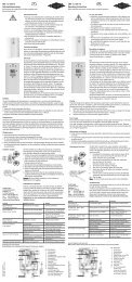
<strong>DBX</strong> BASITRONIC ® 18..27<br />
1. Übersichtsdarstellung 1. Overview<br />
Bei Ersatzteilbestellungen stets Gerätetyp<br />
und Serien nummer angeben!<br />
Wandhalter<br />
Wall bracket<br />
82520<br />
<strong>DBX</strong> Gerätehaube<br />
<strong>DBX</strong> hood<br />
82501<br />
Rückflussverhinderer<br />
Non-return valve<br />
82246<br />
Durchflussgeber<br />
Flow sensor<br />
82526<br />
Temperaturfühler Set<br />
Thermal sensor set<br />
82851<br />
Heizelement mit<br />
Druckschalter<br />
Heating element with<br />
pressure switch<br />
18 kW: 82847<br />
21 kW: 82848<br />
24 kW: 82849<br />
27 kW: 82450<br />
Sicherheits-Temperatur-<br />
Druck-Begrenzer STDB<br />
Safety thermal cut-out STDB<br />
82538<br />
Temperaturfühler Set<br />
Temperature sensor set<br />
82851<br />
Auslaufrohr<br />
Outlet pipe<br />
82529<br />
Warmwasseranschlussstück<br />
Hot water connection<br />
82085<br />
9<br />
8<br />
7<br />
6<br />
3<br />
5<br />
4<br />
3<br />
2<br />
1<br />
22 G½” Einschraubnippel<br />
Screw-in nipples ½”<br />
82110<br />
2<br />
When ordering spare parts, please always<br />
specify the appliance model and serial number.<br />
21 Durchführungstülle<br />
Grommet<br />
82180<br />
10 Geräteunterteil<br />
Bottom part<br />
82505<br />
11 Verbindungsrohr<br />
Connecting pipe<br />
82591<br />
12 Elektronikabdeckung<br />
PCB cover<br />
82852<br />
13 Klapphalter<br />
Control panel support<br />
82573<br />
14 Anschlussklemme<br />
Connecting terminal<br />
82572<br />
15 Einlaufrohr<br />
Inlet pipe<br />
82531<br />
16 Feinfilter<br />
Fine filter<br />
82162<br />
17 Durchflussmengen-<br />
regler<br />
Flow limiter<br />
89111, 89110, 89109<br />
18 Rahmen<br />
Frame<br />
82571<br />
19 Kaltwasseranschlussstück<br />
Cold water connection<br />
82074<br />
20 Spritzwasserschutztülle<br />
Water splash protection<br />
sleeve 82060
Inhaltsverzeichnis Contents<br />
1. Übersichtsdarstellung ...............................2<br />
2. Umwelt und Recycling ..............................3<br />
3. Sicherheitshinweise ................................4<br />
4. Technische Daten ..................................5<br />
5. Abmessungen .....................................5<br />
6. Installation .......................................6<br />
Montageort ......................................6<br />
Wichtiger Hinweis für druckfeste Installationen ...........6<br />
Wandhalter montieren ..............................7<br />
Anschlussstücke installieren ..........................8<br />
Gerät montieren ...................................8<br />
7. Aufputzmontage ..................................9<br />
8. Elektroanschluss. . . . . . . . . . . . . . . . . . . . . . . . . . . . . . . . . . 10<br />
Bauliche Voraussetzungen ..........................10<br />
Lastabwurfbox / -relais .............................10<br />
Elektroanschluss von unten .........................11<br />
Elektroanschluss von oben ..........................12<br />
9. Erstinbetriebnahme ...............................13<br />
Hinweis: Voreingestellte Auslauftemperatur ändern .......13<br />
10. Wartungsarbeiten ................................14<br />
Reinigung und Wechsel des Filtersiebes ...............14<br />
11. Notizen .......................................15<br />
2. Umwelt und Recycling 2. Environment and recycling<br />
Ihr Produkt wurde aus hochwertigen Materialien und Komponenten<br />
entwickelt und hergestellt, die recycelbar und wiederverwendbar<br />
sind. Dieses Symbol auf Produkten und /<br />
oder begleitenden Dokumenten bedeutet, dass elektrische<br />
und elektronische Produkte am Ende ihrer Lebensdauer vom<br />
Hausmüll getrennt entsorgt werden müssen. Bringen Sie bitte<br />
diese Produkte für die Behandlung, Rohstoffrückgewinnung und<br />
Recycling zu den eingerichteten kommunalen Sammelstellen<br />
bzw. Werkstoffsammelhöfen, die diese Geräte kostenlos entgegen<br />
nehmen. Die ordnungsgemäße Entsorgung dieses<br />
Produktes dient dem Umweltschutz und verhindert mögliche<br />
schädliche Auswirkungen auf Mensch und Umwelt, die sich aus<br />
einer unsachgemäßen Handhabung der Geräte am Ende ihrer<br />
Lebensdauer ergeben könnten. Genauere Informationen zur<br />
nächstgelegenen Sammelstelle bzw. Recyclinghof erhalten Sie<br />
bei Ihrer Gemeindeverwaltung. Geschäftskunden: wenn Sie elektrische<br />
und elektronische Geräte entsorgen möchten, treten Sie<br />
bitte mit Ihrem Händler oder Lieferanten in Kontakt. Diese halten<br />
weitere Informationen für Sie bereit. Dieses Symbol ist nur in der<br />
Europäischen Union gültig.<br />
3<br />
1. Overview ........................................2<br />
2. Environment and recycling ........................... 3<br />
3. Safety instructions ................................. 4<br />
4. Technical specifications ............................. 5<br />
5. Dimensions ......................................5<br />
6. Installation ....................................... 6<br />
Installation site ....................................6<br />
Important notice for closed outlet installations ........... 6<br />
Installing the wall bracket ........................... 7<br />
Installing connection pieces .......................... 8<br />
Installing the appliance ............................. 8<br />
7. Direct connection .................................. 9<br />
8. Electrical connection ..............................10<br />
Structural prerequisites ............................ 10<br />
Load shedding box / relay .......................... 10<br />
Electrical connection from below ..................... 11<br />
Electrical connection from above ..................... 12<br />
9. Initial operation ..................................13<br />
Note: Modification of factory preset outlet temperature ... 13<br />
10. Maintenance work ...............................14<br />
Cleaning and replacing the filter strainer .............. 14<br />
11. Notes .........................................15<br />
This symbol on the products and / or accompanying<br />
documents means that used electrical<br />
and electronic products should not be<br />
mixed with general household waste. For<br />
proper treatment, recovery and recycling,<br />
please take these products to designated collection points where<br />
they will be accepted on a free of charge basis. Alternatively, in<br />
some countries you may be able to return your products to your<br />
local retailer upon the purchase of an equivalent new product.<br />
Disposing of this product correctly will help to save valuable<br />
resources and prevent any potential negative effects on human<br />
health and the environment which could otherwise arise from<br />
inappropriate waste handling. Please contact your local authority<br />
for further details of your nearest designated collection point.<br />
Penalties may be applicable for incorrect disposal of this waste,<br />
in accordance with national legislation. If you are a business<br />
user and you wish to discard electrical and electronic equipment,<br />
please contact your dealer or supplier for further information.<br />
This symbol is only valid in the European Union.
<strong>DBX</strong> BASITRONIC ® 18..27<br />
3. Sicherheitshinweise 3. Safety instructions<br />
Montage, erste Inbetriebnahme und Wartung dieses<br />
Gerätes dürfen nur durch einen anerkannten Fachhandwerksbetrieb<br />
erfolgen, der dabei für die Beachtung der<br />
bestehenden Normen und Installationsvorschriften voll<br />
verantwortlich ist. Wir übernehmen keine Haftung für<br />
Schäden, die durch Nichtbeachtung dieser Anleitung entstehen!<br />
• Benutzen Sie das Gerät nur, nachdem es korrekt installiert<br />
wurde und wenn es sich in technisch einwandfreiem Zustand<br />
befindet.<br />
• Das Gerät ist nur für den Hausgebrauch und ähnliche Zwecke<br />
innerhalb geschlossener und frostfreier Räume geeignet und<br />
darf nur zum Erwärmen von Trinkwasser verwendet werden.<br />
Es ist nicht zum Betrieb mit vorgewärmten Wasser zugelassen.<br />
• Das Gerät darf niemals Frost ausgesetzt werden.<br />
• Das Gerät muss dauerhaft und zuverlässig geerdet werden.<br />
• Der auf dem Typenschild angegebene minimale spezifische<br />
Wasserwiderstand darf nicht unterschritten werden.<br />
• Der auf dem Typenschild angegebene maximale Wasserdruck<br />
darf zu keinem Zeitpunkt überschritten werden.<br />
• Vor der ersten Inbetriebnahme sowie nach jeder Entleerung<br />
(z.B. durch Arbeiten in der Wasserinstallation oder wegen<br />
Frostgefahr oder Wartung) muss das Gerät gemäß den<br />
Hinweisen in der Anleitung ordnungsgemäß entlüftet werden.<br />
• Öffnen Sie niemals das Gerät, ohne vorher die Stromzufuhr<br />
zum Gerät dauerhaft unterbrochen zu haben.<br />
• Nehmen Sie am Gerät oder an den Elektro- und<br />
Wasserleitungen keine technischen Änderungen vor.<br />
• Beachten Sie, dass Wassertemperaturen über ca. 43 °C<br />
besonders bei Kindern als heiß empfunden werden und ein<br />
Verbrennungsgefühl hervorrufen können. Bedenken Sie, dass<br />
nach längerer Durchlaufzeit auch die Armaturen entsprechend<br />
heiß werden.<br />
• Die Wassereinlauftemperatur darf 30 °C nicht überschreiten.<br />
• Im Störungsfall schalten Sie sofort die Sicherungen<br />
aus. Bei einer Undichtigkeit am Gerät schließen Sie<br />
sofort die Kaltwasserzuleitung. Lassen Sie die Störung<br />
nur vom Werkskundendienst oder einem anerkannten<br />
Fachhandwerksbetrieb beheben.<br />
• Dieses Gerät ist nicht dafür bestimmt durch Personen (einschließlich<br />
Kinder) mit eingeschränkten physischen, sensorischen<br />
oder geistigen Fähigkeiten oder mangels Erfahrung<br />
und/oder mangels Wissen benutzt zu werden, es sei denn<br />
sie werden durch eine für ihre Sicherheit zuständige Person<br />
beaufsichtigt oder erhielten von ihr Anweisungen wie das<br />
Gerät zu benutzen ist. Kinder sollten beaufsichtigt werden, um<br />
sicherzustellen, dass sie nicht mit dem Gerät spielen.<br />
4<br />
Installation, initial operation and maintenance of this<br />
appliance must only be conducted by an authorised professional,<br />
who will then be responsible for adherence<br />
to applicable standards and installation regulations. We<br />
assume no liability for any damages caused by failure to<br />
observe these instructions.<br />
• Do not use the appliance until it has been correctly installed<br />
and unless it is in perfect working order.<br />
• The appliance is only suitable for domestic use and similar<br />
applications inside closed, frost-free rooms, and must only<br />
be used to heat incoming water from mains supply. It is not<br />
allowed to be used with preheated water.<br />
• The appliance must never be exposed to frost.<br />
• The appliance must be earthed at all times.<br />
• The minimal specific water resistance must not fall below the<br />
value stated on the label.<br />
• The maximum water pressure must not exceed the value on<br />
the label.<br />
• Before commissioning for the first time and each time the<br />
appliance is emptied (e.g. due to work on the plumbing system,<br />
if there is a risk of freezing or in case of maintenance),<br />
the appliance must be vented correctly in accordance with the<br />
instructions in this manual.<br />
• Do not remove the front cover under any circumstances before<br />
switching off the mains electrical supply to the unit.<br />
• Never make technical modifications, either to the appliance<br />
itself or the electrical leads and water pipes.<br />
• Pay attention to the fact that water temperatures in excess of<br />
approx. 43 °C are perceived as hot, especially by children, and<br />
may cause a feeling of burning. Please note that the fittings<br />
and taps may be very hot when the appliance has been in use<br />
for some time.<br />
• Water inlet temperature must never exceed 30 °C.<br />
• In case of malfunction, disconnect the fuses immediately. In<br />
case of leaks, cut off the cold water supply instantly. Repairs<br />
must only be carried out by the customer service department<br />
or an authorised professional.<br />
• This appliance must not be used by any person (including<br />
children) with limited physical, sensorial or mental abilities<br />
or failing experience and/or knowledge unless they are<br />
supervised by a person responsible for their safety or received<br />
instructions about how to use the appliance.Children should<br />
be supervised in order to make sure that they do not play with<br />
the appliance.
4. Technische Daten 4. Technical specifications<br />
Typ<br />
466<br />
363<br />
56<br />
231<br />
170<br />
3 2 1<br />
100<br />
97<br />
<strong>DBX</strong> BASITRONIC ® 18 .. 27<br />
<strong>DBX</strong> 18 <strong>DBX</strong> 21 <strong>DBX</strong> 24 <strong>DBX</strong> 27<br />
Bestell-Nr. 34118 34121 34124 34127 Article no.<br />
Nennleistung / -strom 18 kW (26 A) 21 kW (30 A) 24 kW (35 A) 27 kW (39 A) Capacity set / current<br />
Elektroanschluss 3/PE 380..415V AC 3/PE 400V AC Electrical connection<br />
Erforderl. Leiterquerschnitt 4.0 mm 2 4.0 mm 2 6.0 mm 2 1) 6.0 mm 2 Min. required cable size<br />
Warmwasser- max. at ∆t = 28 K<br />
leistung (l/min) 2) max. at ∆t = 38 K<br />
9,2<br />
6,8<br />
10,7<br />
7,9<br />
5<br />
12,3<br />
9,0<br />
13,8<br />
10,2<br />
231<br />
Model<br />
Hot water (l/min) 2) max. at ∆t = 28 K<br />
max. at ∆t = 38 K<br />
Nenninhalt 0,4 l Rated volume<br />
Bauart<br />
geschlossen, 1 MPa (10 bar) Nennüberdruck /<br />
Pressure type 1 MPa (10 bar)<br />
Type<br />
Heizsystem Blankdraht IES ® / Bare wire heating system IES ® Heating system<br />
Einsatzbereich bei 15 °C:<br />
Required specific<br />
spez. Wasserwiderstand<br />
≥ 1100 Ωcm<br />
water resistance @ 15 °C<br />
spez. elektr. Leitfähigkeit<br />
≤ 90 mS/m<br />
Specific electrical conductivity<br />
Einlauftemperatur ≤ 30 °C Inlet temperature<br />
Einschalt- – max. Durchfluss 3) 2,5 – 7,0 l/min 2,5 – 8,0 l/min 2,5 – 8,0 l/min 2,5 – 9,0 l/min<br />
Flow rate to switch on – max. flow<br />
rate 3)<br />
Druckverlust 0,2 bar bei / at 2,5 l/min 1,3 bar bei / at 9,0 l/min 4) Pressure loss<br />
Temperatureinstellbereich 30 °C – 60 °C Temperature range<br />
Wasseranschluss G ½“ Water connection<br />
Gewicht (mit Wasserfüllung) 3,65 kg Weight (when filled with water)<br />
Schutzklasse nach VDE I VDE class of protection<br />
Geräuschprüfzeugnis PA-IX 6762/I Noise level test certificate<br />
Schutzart / Sicherheit IP25 Type of protection / safety<br />
1) Bei Austausch eines 21kW/380V-Gerätes kann der Leiterquerschnitt 4 mm 2<br />
übernommen werden.<br />
2) Mischwasser<br />
3) Durchfluss begrenzt, um optimale Temperaturerhöhung zu erreichen<br />
4) Ohne Durchflussmengenregler<br />
1) When replacing a 21 kW / 380 V appliance<br />
the cable size of 4 mm 2 can be adopted.<br />
2) Mixed water<br />
3) Flow rate limited to achieve optimum temperature rise<br />
4) Without flow regulator<br />
5. Abmessungen 5. Dimensions<br />
Maßangaben in mm<br />
Dimensions in mm
<strong>DBX</strong> BASITRONIC ® 18..27<br />
Für dieses Gerät ist aufgrund der Landes bauordnungen<br />
ein allgemeines bauaufsichtliches<br />
Prüfzeugnis zum Nachweis der Verwendbarkeit<br />
hinsichtlich des Geräusch verhaltens erteilt.<br />
Based on the national constitution guidelines<br />
a general test certificate concerning the evidence<br />
of applicability of noice behaviour is<br />
granted.<br />
6. Installation 6. Installation<br />
Zu beachten sind:<br />
• VDE 0100<br />
• EN 8062<br />
• Bestimmungen der örtlichen<br />
Energie und Wasserversorgungsunternehmen<br />
• Angaben auf Typenschild<br />
• Technische Daten<br />
Montageort<br />
• Gerät nur in einem frostfreien Raum<br />
installieren. Das Gerät darf niemals<br />
Frost ausgesetzt werden.<br />
• Das Gerät ist für eine Wandmontage<br />
vorgesehen und muss senkrecht mit<br />
untenliegenden Wasseranschlüssen<br />
installiert werden.<br />
• Das Gerät entspricht der Schutzart IP25<br />
und darf gemäß VDE 0100 Teil 701 im<br />
Schutzbereich 1 installiert werden.<br />
• Um Wärmeverluste zu vermeiden,<br />
sollte die Entfernung zwischen<br />
<strong>Durchlauferhitzer</strong> und Zapfstelle möglichst<br />
gering sein.<br />
• Für Wartungsarbeiten sollte in der<br />
Zuleitung ein Absperrventil installiert<br />
werden. Das Gerät muss für Wartungszwecke<br />
zugänglich sein.<br />
• Es können Wasserleitungen aus<br />
Kupfer oder Stahl ein gesetzt werden.<br />
Kunstoffrohre dürfen nur verwendet<br />
werden, wenn diese DIN 16893 Reihe 2<br />
entsprechen. Die Warmwasserleitungen<br />
müssen wärmegedämmt sein.<br />
• Der spezifische Widerstand des Wassers<br />
muss bei 15 °C mindestens 1100 Ω cm<br />
betragen. Der spezifische Widerstand<br />
des Wassers kann bei Ihrem Wasserversorgungs<br />
unternehmen erfragt<br />
werden.<br />
Wichtiger Hinweis für<br />
druckfeste Installationen<br />
Falls ein Rückfluss verhin de rer in der<br />
Installation notwen dig ist, darf dieser<br />
nur in der Warm wasser leitung<br />
nach dem Durch lauf erhitzer installiert<br />
werden.<br />
Ein Rückflussverhinderer in der<br />
Kaltwasserzuleitung vor dem<br />
<strong>Durchlauferhitzer</strong> ist nicht zulässig!<br />
6<br />
The following regulations must be<br />
observed:<br />
• Installation must comply with all<br />
statutory regulations, as well as<br />
those of the local electricity and<br />
water supply companies.<br />
• The specifications on the rating<br />
plate<br />
• Technical specifications<br />
Installation site<br />
• Appliance must only be installed in<br />
frost-free rooms. Never expose appliance<br />
to frost.<br />
• The Appliance must be wall mounted<br />
and has to be installed with water connectors<br />
downward.<br />
• The appliance complies with protection<br />
type IP25 and may therefore be<br />
installed in protection zone 1 according<br />
to VDE 0100 part 701.<br />
• In order to avoid thermal losses, the<br />
distance between the instantaneous<br />
water heater and the tapping point<br />
should be as small as possible.<br />
• For maintenance work, a shut-off valve<br />
should be installed in the supplyline.<br />
The appliance must be accessible for<br />
maintenance work.<br />
• Copper or steel connecting pipes may<br />
be used. Plastic pipes may only be used<br />
if they conform to DIN 16893, Series 2.<br />
The hot water pipes must be thermally<br />
insulated.<br />
• The specific resistance of the water<br />
must be at least 1100 Ωcm at 15°C.<br />
The specific resistance can be asked for<br />
with your water distribution company.<br />
Important notice for closed<br />
outlet installations<br />
If a non return valve is neces sary for<br />
installation it must be installed in the<br />
hot water outlet line after the instant<br />
water heater.<br />
A non return valve must NOT be fitted in<br />
the cold inlet line before the appliance!
(22)<br />
6. Installation 6. Installation<br />
Wandhalter montieren<br />
Wenn Sie den <strong>Durchlauferhitzer</strong> <strong>DBX</strong> im<br />
Austausch gegen ein anderes Fabrikat<br />
montieren, müssen in der Regel keine<br />
neuen Löcher für den Wandhalter gebohrt<br />
werden. In diesem Fall brauchen Sie nur<br />
die Einschraubnippel (22) wie unter 2.<br />
beschrieben einzuschrauben und den<br />
Wandhalter zu montieren.<br />
1. Spülen Sie die Wasserzuleitungen<br />
vor der Installation gründlich<br />
durch, um Schmutz aus den<br />
Leitungen zu entfernen.<br />
2. Schrauben Sie die Einschraubnippel mit<br />
einem 12 mm Innensechskantschlüssel<br />
in die beiden Wand anschlüsse. Der<br />
Überstand der Einschraubnippel muss<br />
nach dem Festziehen 12 mm betragen.<br />
3. Halten Sie die mitgelieferte Montageschablone<br />
an die Wand und richten<br />
Sie sie so aus, dass die Löcher in der<br />
Schablone über die Anschlüsse passen.<br />
Zeichnen Sie die Bohrlöcher entsprechend<br />
der Schablone an und bohren<br />
Sie die Löcher mit einem 6 mm -Bohrer.<br />
Setzen Sie die mitgelieferten Dübel<br />
ein und schrauben Sie den Wandhalter<br />
(9) an.<br />
4. Fliesenversatz oder Unebenheiten<br />
lassen sich bis zu 30 mm durch die mitgelieferten<br />
Distanzhülsen ausgleichen.<br />
Die Distanzhülsen werden zwischen<br />
Wand und Wandhalter montiert.<br />
7<br />
Installing the wall bracket<br />
If you install the instantaneous water<br />
heater <strong>DBX</strong> instead of a conventional<br />
instantaneous water heater, there is generally<br />
no need to drill holes for the wall<br />
holder. In this case, you only need<br />
to screw in the double nipples (22) as<br />
described in 2. and to secure the wall<br />
bracket.<br />
1. Thoroughly rinse the water supply<br />
pipes before installation to remove<br />
soiling from the pipes.<br />
2. Using a 12 mm hexagon socket screw<br />
key, screw the screw-in nipples into<br />
the wall connections. After tightening,<br />
the double nipples must protrude by<br />
12 mm.<br />
3. Hold the included mounting template<br />
on the wall and align it so that the<br />
holes in the template fit over the connections.<br />
Mark the drill holes according<br />
to the template and drill them using a<br />
6 mm drill. Insert the included dowels<br />
and screw in the wall bracket (9).<br />
4. Offset tiling or uneven surfaces can be<br />
compensated by up to 30 mm with the<br />
aid of the spacers supplied. The spacers<br />
are fitted between the wall and wall<br />
bracket.
<strong>DBX</strong> BASITRONIC ® 18..27<br />
(1)<br />
(19)<br />
S<br />
6. Installation 6. Installation<br />
Anschlussstücke installieren<br />
1. Schrauben Sie gemäß Abbildung das<br />
Kaltwasseranschlussstück (19) mit<br />
Überwurfmutter und der 1/2“-Dichtung<br />
an den Kaltwasseranschluss.<br />
2. Schrauben Sie das Warmwasseranschlussstück<br />
(1) mit Überwurfmutter<br />
und der 1/2“-Dichtung an<br />
den Warmwasseranschluss.<br />
Gerät montieren<br />
1. Zum Öffnen des Gehäuses die Blende<br />
abnehmen und die zentrale Haubenschraube<br />
lösen.<br />
• Im Austauschfall kann es vor kom men,<br />
dass die Elektro zuleitung im oberen<br />
Gerätebereich vorhanden ist.<br />
Der Elektroanschluss erfolgt<br />
dann gemäss der Beschreibung<br />
»Elektroanschluss von oben«.<br />
2. Setzen Sie das Gerät auf den Wandhalter<br />
(9), so dass die Gewindestange<br />
des Wandhalters in das vorgesehene<br />
Loch des Gerätes passt. Durch vorsichtiges<br />
Biegen der Gewinde stange des<br />
Wandhalters lassen sich gegebenenfalls<br />
kleine Korrekturen vornehmen. Die<br />
Wasseranschluss leitungen des Gerätes<br />
müssen sich jedoch ohne Gewaltanwendung<br />
anschrauben lassen.<br />
3. Schrauben Sie die beiden 3/8“-Überwurf<br />
muttern der Wasser anschlussleitungen<br />
des Gerätes jeweils mit der<br />
3/8“-Dichtung auf die installierten<br />
Anschlussstücke.<br />
4. Schrauben Sie die Kunststoffrändelmutter<br />
auf die Gewindestange des<br />
Wandhalters.<br />
8<br />
Installing connection pieces<br />
1. As shown in the illustration, screw the<br />
cold water connection piece (19) with<br />
the union nut and the 1/2“ seal onto<br />
the cold water connection.<br />
2. Screw the hot water connection piece<br />
(1) with the union nut and the 1/2“<br />
seal onto the hot water connection.<br />
Installing the appliance<br />
1. To open the appliance hood, take off<br />
the faceplate and unscrew the main<br />
hood screw.<br />
• When replacing an appliance, the electrical<br />
power supply cable may be connected<br />
in the upper part. Only in such<br />
case, follow the instructions “Electrical<br />
connection from above”.<br />
2. Place the appliance on the heater<br />
bracket (9) so that the threaded rod<br />
of the wall bracket fits in the provided<br />
hole of the appliance. If necessary,<br />
slight corrections are possible by carefully<br />
bending the threaded rod of the<br />
wall bracket. However, it must be possible<br />
to screw on the water connection<br />
pipes of the appliance without applying<br />
force.<br />
3. Screw the two 3/8“ union nuts of the<br />
appliance‘s water connection pipes,<br />
each with the 3/8“ seal, onto the fittings.<br />
4. Screw the plastic knurled nut onto the<br />
threaded rod of the wall bracket.
(19 c)<br />
6. Installation 6. Installation<br />
5. Öffnen Sie die Wasserzuleitung und<br />
drehen Sie das Absperrventil (19c)<br />
im Kaltwasseranschlussstück (19)<br />
langsam auf (Pos.I). Prüfen Sie alle<br />
Verbindungen auf Dichtigkeit.<br />
6. Öffnen und schließen Sie danach<br />
mehrfach das zugehörige Warm wasserzapfventil<br />
bis keine Luft mehr aus<br />
der Leitung austritt und der <strong>Durchlauferhitzer</strong><br />
luftfrei ist.<br />
Bei Aufputzmontage sind die beiden 1/2“<br />
Einschraubnippel (22) und die 1/2“ Dichtungen<br />
mit den 1/2“ Überwurfmuttern<br />
des Warmwasser- (1) und Kaltwasseranschlussstückes<br />
(19) zu verschrauben.<br />
Die beiden 1/2“ Blindkappen der<br />
seitlichen Abgänge des Warm- und<br />
Kalt wasser anschlussstückes sind zu<br />
demontie ren und mit dem offenen Ende<br />
der Einschraubnippel zu verschrau ben. Die<br />
Warm- und Kalt wasser anschlussstücke<br />
sind dann mit den 3/8“ Dichtungen an<br />
die 3/8“ Überwurfmutter des Gerätes und<br />
Auslaufrohres zu verschrauben.<br />
Bei Aufputzmontage ist es sinnvoll,<br />
das Gerät mittels der mitgelieferten<br />
Distanzhülsen gemäß nebenstehender<br />
Zeichnung auf Abstand zu montieren.<br />
Dabei ist zu beachten, dass auch die beiden<br />
Befestigungsbohrungen im unteren<br />
Rohranschlussbereich benutzt werden.<br />
Die Bördelseite der Rohre sind mit 1/2“<br />
Überwurfmuttern und 1/2“ Dichtungen<br />
an die seitlichen 1/2“ Abgänge des<br />
Warm- und Kaltwasseranschlussstückes<br />
zu schrauben. Abschließend sind die<br />
Aus brüche für die Rohre in der Haube<br />
mit einem stumpfen Gegenstand herauszubrechen.<br />
Bei Aufputzmontage beachten:<br />
Sieb in das Kaltwasseranschlussstück<br />
einsetzen!<br />
9<br />
5. Open the water supply line to the unit<br />
and slowly open the shut-off valve<br />
(19c) in the cold water connection<br />
piece (19) (Pos.I). Check all connec tions<br />
for leaks.<br />
6. Next, open and close the hot water<br />
tapping valve several times until no<br />
more air emerges from the line and<br />
all air has been eliminated from the<br />
instantaneous water heater.<br />
7. Aufputzmontage 7. Direct connection<br />
For direct connection, the two 1/2“ screwin<br />
nipples (22) and the 1/2“ seals must be<br />
screwed into the 1/2“ union nuts of the<br />
hot-water (1) and cold-water (19) connectors.<br />
The two 1/2“ caps of the side<br />
outlets of the hot-water and cold-water<br />
connectors must be removed and screwed<br />
onto the open end of the screw-in nipples.<br />
The hot-water and cold-water connectors<br />
must then be screwed into the 3/8“ union<br />
nut of the appliance and delivery pipe,<br />
together with the 3/8“ seals.<br />
For direct connection, it is advisable to<br />
mount the appliance at a distance as illustrated<br />
alongside, using the spacer sleeves<br />
supplied. It should therefore be noted that<br />
the two fixing holes near the lower pipe<br />
connections are also used.<br />
The flared end of the pipes must be<br />
screwed into the 1/2“ side outlets of the<br />
hot-water and cold-water connectors with<br />
1/2“ union nuts and 1/2“ seals. The holes<br />
required for the pipes must then be broken<br />
out of the housing with the aid of a<br />
blunt implement.<br />
In case of direct connection please<br />
note: Put the strainer into the cold<br />
water connection!
<strong>DBX</strong> BASITRONIC ® 18..27<br />
Schaltplan / Wiring diagram<br />
2 1<br />
1. Elektronik<br />
2. Heizelement<br />
3. Sicherheitsdruckbegrenzer und<br />
Sicherheitstemperatur begrenzer<br />
4. Klemmleiste<br />
1. Electronic circuitry<br />
2. Heating element<br />
3. Safety pressure switch and Safety<br />
thermal cut-out<br />
4. Terminal strip<br />
3<br />
4<br />
8. Elektroanschluss 8. Electrical connection<br />
Nur durch den Fachmann!<br />
Zu beachten sind:<br />
• VDE 0100<br />
• EN8062<br />
• Bestimmungen der örtlichen<br />
Energie und Wasserversorgungsunternehmen<br />
• Angaben Typenschild<br />
• Technische Daten<br />
• Gerät an Schutzleiter anschließen!<br />
Bauliche Voraussetzungen<br />
• Das Gerät muss dauerhaft an fest<br />
verlegte Leitungen angeschlossen<br />
werden. Das Gerät muss an den<br />
Schutzleiter angeschlossen werden.<br />
Kabelquerschnitt maximal 10mm2 .<br />
• Die Elektroleitungen müssen sich in<br />
einem einwandfreien Zustand befinden<br />
und dürfen nach der Montage nicht<br />
mehr berührbar sein.<br />
• Installationsseitig ist eine allpolige<br />
Trennvorrichtung mit einer Kontaktöffnungsweite<br />
von mindestens<br />
3 mm pro Pol vorzusehen (z.B. über<br />
Sicherungen).<br />
• Zur Absicherung des Gerätes ist ein<br />
Sicherungselement für Leitungsschutz<br />
mit einem dem Gerätenennstrom angepassten<br />
Auslösestrom zu montieren.<br />
Lastabwurfrelais<br />
Beim Anschluss weiterer Drehstromgeräte<br />
kann ein Lastabwurfrelais für elektronische<br />
<strong>Durchlauferhitzer</strong> (CLAGE Art.Nr.<br />
82250) an den Außenleiter L2 angeschlossen<br />
werden.<br />
Je nach lokalen Bedingungen ist es nicht<br />
ausgeschlossen, dass es im niedrigen<br />
Leistungsbereich des <strong>Durchlauferhitzer</strong>s<br />
(niedrige Warmwasser temperatur und<br />
geringer Durchfluss) zu einem Flackern der<br />
Lastabwurfrelais kommen kann. Es muss<br />
dann eine höhere Warmwassertemperatur<br />
und ein höherer Durchfluss eingestellt<br />
werden.<br />
Wir empfehlen unsere Gerätetypen<br />
DEX und DSX, falls der Betrieb mit<br />
Lastabwurfrelais notwendig ist. Diese<br />
Geräte verfügen über eine besondere<br />
Betriebsart für die Verwendung mit<br />
Lastabwurfrelais.<br />
10<br />
Only by a specialist!<br />
Please observe:<br />
• The installation must comply with<br />
current IEC and national local<br />
regulations or any particular regulations,<br />
specified by the local electricity<br />
supply company<br />
• Observe the rating plate and technical<br />
specifications<br />
• The unit must be earthed!<br />
Structural prerequisites<br />
• The appliance must be installed via a<br />
permanent connection. Heater must<br />
be earthed! A maximum cable size of<br />
10 mm2 must be observed.<br />
• The electric wiring should not be<br />
injured. After mounting, the wiring<br />
must not be direct accessible.<br />
• An all-pole disconnecting device (e.g.<br />
via fuses) with a contact opening<br />
width of at least 3 mm per pole should<br />
be provided at the installation end.<br />
• To protect the appliance, a fuse element<br />
must be fitted with a tripping<br />
current commensurate with the nominal<br />
current of the appliance.<br />
Load shedding relay<br />
If further three-phase appliances are connected,<br />
a load shedding relay (82250) can<br />
be connected to phase conductor L2 .<br />
Depending on local conditions a jitter<br />
of the load shedding relay might appear<br />
caused by low power consumption of the<br />
instantaneous hot water heater (low temperature<br />
set point or low water flow rate).<br />
In this case it has to be set a higher water<br />
temperature or higher water flow rate.<br />
We recommend our heaters DEX and DSX<br />
as these heaters have a special operation<br />
mode for load shedding relays.
(20) (14) (13)<br />
8. Elektroanschluss 8. Electrical connection<br />
Elektroanschluss von unten<br />
Vergewissern Sie sich vor dem<br />
Anschließen des Gerätes an das elektrische<br />
Netz, dass die Stromversorgung<br />
ausgeschaltet ist!<br />
1. Manteln Sie das Anschlusskabel<br />
ungefähr 6 cm über dem Wandaustritt<br />
ab. Schieben Sie die Spritzwasserschutztülle<br />
(20) mit der kleineren<br />
Öffnung voran über das Anschlusskabel,<br />
so dass die Schutztülle wandbündig<br />
abschließt. Diese verhindert,<br />
dass eventuell eindringendes Wasser<br />
mit den Elektroleitungen in Kontakt<br />
kommt.<br />
Sie darf nicht beschädigt sein! Die<br />
Schutztülle muss verwendet werden!<br />
2. Klapphalter (13) nach rechts klappen.<br />
3. Isolieren Sie die Kabel ab und schließen<br />
diese an die Anschlussklemmen<br />
gemäß des auf S. 10 abgebildeten<br />
Schaltplanes an. Das Gerät ist an den<br />
Schutzleiter anzuschließen.<br />
4. Ziehen Sie die Schutztülle so weit über<br />
die Anschlusskabel, dass die Schutztülle<br />
einwandfrei in die Aussparung der<br />
Zwischenwand passt. Achten Sie dabei<br />
auf die Ausrichtung der Schutz tülle<br />
entsprechend der Abbildung. Klappen<br />
Sie den Klapphalter zurück und rasten<br />
Sie ihn auf der Heizpatrone ein.<br />
5. Setzen Sie das Gehäuse auf das Gerät<br />
und drehen Sie die Befestigungsschraube<br />
ein. Danach können Sie die<br />
Blende aufrasten.<br />
Hinweis:<br />
Bei Bedarf kann die Anschlussklemme<br />
(14) in den oberen Gerätebereich verlegt<br />
werden. Bitte folgen Sie hierzu den<br />
Anweisungen im nächsten Abschnitt.<br />
11<br />
Electrical connection from<br />
below<br />
Check that the power supply is<br />
switched off prior to electrical connection.<br />
1. Strip approximately 6 cm off the connecting<br />
cable above the wall outlet.<br />
With the smaller opening ahead, slide<br />
the water splash protection sleeve (20)<br />
over the connecting cable so that the<br />
sleeve is flush with the wall. This prevents<br />
any leak ing water from coming<br />
into contact with the electrical leads. It<br />
must not become damaged! The protection<br />
sleeve must be used!<br />
2. Open the control panel support (13)<br />
rightwards.<br />
3. Insulate the cables and plug them in<br />
the connecting terminals according to<br />
the wiring diagram on page 10. The<br />
appliance must be earthed.<br />
4. Pull the protective sleeve over the connecting<br />
cables until the sleeve fits perfectly<br />
in the recess of the intermediate<br />
panel. Adjust the water splash protection<br />
sleeve as illustrated. Reinsert the<br />
front part of the inter mediate panel.<br />
Reinsert the control panel and lock it<br />
on the the heating element.<br />
5. Place the hood on the appliance and<br />
screw in the fastening screw. After that<br />
you can reinsert the faceplate.<br />
Note:<br />
If necessary, the connecting terminal (14)<br />
can be displaced to the upper part of the<br />
appliance. If you want to do so, please follow<br />
the instructions in the next chapter.
<strong>DBX</strong> BASITRONIC ® 18..27<br />
S<br />
8. Elektroanschluss 8. Electrical connection<br />
Elektroanschluss von oben<br />
Vergewissern Sie sich vor dem<br />
Anschließen des Gerätes an das elektrische<br />
Netz, dass die Stromversorgung<br />
ausgeschaltet ist!<br />
1. Öffnen Sie die im oberen Gerätebereich<br />
vorhandene Soll bruchstelle (S)<br />
an der Prägung durch kräftigen Druck<br />
mit einem stumpfen Werkzeug (z.B.<br />
Schraubendreher).<br />
2. Schneiden Sie die Durchfüh rungstülle<br />
(21) entsprechend dem<br />
Zuleitungsquerschnitt auf. Dabei soll<br />
die Öffnung in der Tülle etwas kleiner<br />
als der Quer schnitt des Kabels sein, um<br />
einen optimalen Schutz gegen Wasser<br />
zu erzielen. Passen Sie die Tülle in den<br />
Durchbruch ein. Die Schutztülle muss<br />
verwendet werden!<br />
3. Manteln Sie das Elektrokabel ungefähr<br />
6 cm über dem Wand austritt ab.<br />
Nehmen Sie das vorbereitete Gerät so<br />
in die Hand, dass Sie mit der anderen<br />
Hand das Kabel in die Gummi tülle führen<br />
können.<br />
4. Setzen Sie das Gerät so auf den<br />
Wandhalter (9), dass die Gewindestange<br />
des Wandhalters in das vorgesehene<br />
Loch des Gerätes passt.<br />
5. Lösen Sie die Befestigungsschraube der<br />
Anschlussklemme. Versetzen Sie die<br />
Anschlussklemme auf den oberen Fuß.<br />
Befestigen Sie die Anschluss klemme<br />
dort wieder.<br />
6. Isolieren Sie die Kabel ab und schließen<br />
diese an die Anschlussklemmen gemäß<br />
des Schaltplanes an. Das Gerät ist an<br />
den Schutzleiter anzuschließen.<br />
7. Setzen Sie das Gehäuse auf das Gerät<br />
und drehen Sie die Befestigungsschraube<br />
ein. Danach können Sie die<br />
Blende aufrasten.<br />
12<br />
Electrical connection from<br />
above<br />
Check that the power supply is<br />
switched off prior to electrical connection.<br />
1. Open the prepared breaking point (S)<br />
in the upper part of the appliance by<br />
pressing with a blunt implement (e.g.<br />
srewdriver).<br />
2. Slit the grommet (21) to match the<br />
cable size. The opening in the grommet<br />
should be slightly smaller than<br />
the cross-section of the cable in order<br />
to ensure optimum protection against<br />
water. Fit the grommet into the opening.<br />
The protection grommet must be<br />
used!<br />
3. Strip the cable roughly 6 cm above the<br />
point where it emerges from the wall.<br />
Hold the prepared appliance so that<br />
you can route the cable into the grommet<br />
with the other hand.<br />
4. Place the appliance on the heater<br />
bracket (9) so that the threaded rod<br />
of the wall bracket fits in the provided<br />
hole of the appliance.<br />
5. Unscrew the fastening screw of the<br />
connecting terminal. Displace the connecting<br />
terminal to the upper foot.<br />
Affix the connecting terminal again.<br />
6. Insulate the cables and plug them in<br />
the connecting terminals according to<br />
the wiring diagram. The appliance must<br />
be earthed.<br />
7. Place the hood on the appliance and<br />
screw in the fastening screw. After<br />
that you can reinsert the faceplate.
9. Erstinbetriebnahme 9. Initial operation<br />
1. Vor dem elektrischen Anschluss das<br />
Leitungsnetz und das Gerät durch<br />
mehrfaches, langsames Öffnen<br />
und Schließen des Warmwasser-<br />
Zapfventiles mit Wasser füllen und<br />
so voll stän dig entlüften. Nach jeder<br />
Ent leerung (z. B. nach Arbeiten in<br />
der Wasserinstallation, wegen Frostgefahr<br />
oder nach Repara turen am<br />
Gerät) muss das Gerät vor der Wiederinbetriebnahme<br />
erneut entlüftet werden.<br />
2. Schalten Sie die Stromzufuhr zum<br />
Gerät ein.<br />
3. Öffnen Sie das Warmwasserzapfventil.<br />
Überprüfen Sie die Funktion des<br />
<strong>Durchlauferhitzer</strong>s.<br />
4. Machen Sie den Benutzer mit dem<br />
Gebrauch vertraut und übergeben Sie<br />
ihm die Gebrauchsanleitung.<br />
5. Registrieren Sie Ihr Gerät online auf<br />
unserer Homepage www.clage.de oder<br />
füllen Sie die Registrierkarte aus und<br />
senden diese an den Zentralkundendienst.<br />
Hinweis: Voreingestellte<br />
Auslauftemperatur ändern<br />
Die Warmwasserauslauftemperatur<br />
ist werkseitig auf 50 °C voreingestellt.<br />
Durch drehen mit einem kleinen<br />
Schlitzschraubendreher (Klingenbreite<br />
ca. 2 mm) am Verstellpotentiometer<br />
kann diese Voreinstellung zwischen zwei<br />
Anschlägen im Bereich von ca. 30 °C bis<br />
60 °C verändert werden.<br />
Die eingestellte Warmwasser auslauftempe<br />
ratur wird durch Drehung im<br />
Uhrzeigersinn verringert und durch<br />
Drehung gegen den Uhrzeigersinn erhöht.<br />
13<br />
1. Before making the electrical connection,<br />
fill the mains and the appliance<br />
with water by carefully opening and<br />
closing the hot water tap in order to<br />
vent completely. After every draining<br />
(e.g. after work on the plumbing system<br />
or following repairs to the appliance),<br />
the heater must be re-vented in<br />
this way before starting it up again.<br />
2. Switch on the power supply to the<br />
appliance.<br />
3. Open the hot water tap. Check the<br />
function of the appliance.<br />
4. Explain the user how the instant-aneous<br />
water heater works and hand over<br />
the operating instructions.<br />
5. Use the online registration on our website<br />
www.clage.com or fill in the guarantee<br />
registration card and send it to<br />
the CLAGE Central Customer Service.<br />
Note: Modification of factory<br />
preset outlet temperature<br />
The factory set hot water outlet temperature<br />
is 50 °C.<br />
This factory setting can be modified within<br />
the range of approx. 30 °C to 60 °C by<br />
turning the readout potentio meter with a<br />
slotted screwdriver (width approx. 2 mm).<br />
The hot water outlet temperature will<br />
be decreased by clockwise rotation and<br />
increased by counterclockwise rotation.
<strong>DBX</strong> BASITRONIC ® 18..27<br />
(19 b)<br />
(19 a)<br />
(19 c)<br />
10. Wartungsarbeiten 10. Maintenance work<br />
Wartungsarbeiten dürfen nur von<br />
einem anerkannten Fachhandwerksbetrieb<br />
durchgeführt werden.<br />
Reinigung und Wechsel des<br />
Filtersiebes<br />
Der Kaltwasseranschluss des <strong>Durchlauferhitzer</strong>s<br />
<strong>DBX</strong> ist mit einem integrierten<br />
Absperrventil und Sieb ausgestattet.<br />
Durch Verschmutzung des Siebes kann die<br />
Warmwasserleistung vermindert werden,<br />
so dass die Reinigung beziehungsweise<br />
der Austausch des Siebes wie folgt vorzunehmen<br />
ist:<br />
1. Schalten Sie den <strong>Durchlauferhitzer</strong> an<br />
den Haussicherungen spannungsfrei<br />
und sichern Sie diese gegen unbeabsichtigtes<br />
Wiedereinschalten.<br />
2. Nach Öffnen der Gerätehaube drehen<br />
Sie das Absperr ventil (19c) im Kaltwasseranschlussstück<br />
zu (Position II).<br />
3. Drehen Sie die<br />
Verschlussschraube (19b) aus dem<br />
Kaltwasseranschlussstück und nehmen<br />
Sie das Sieb (19a) herau s.<br />
4. Das Sieb kann nun gereinigt beziehungsweise<br />
ersetzt werden.<br />
5. Nach Einbau des Siebes drehen Sie die<br />
Verschlussschraube fest.<br />
6. Drehen Sie das Absperrventil im<br />
Kaltwasseranschlussstück langsam<br />
auf (Position I).<br />
7. Entlüften Sie das Gerät, indem Sie das<br />
zugehörige Warmwasserzapfventil<br />
mehrfach langsam öffnen und schließen,<br />
bis keine Luft mehr aus der<br />
Leitung austritt.<br />
8. Setzen Sie die Gerätehaube auf.<br />
Danach schalten Sie die Spannung an<br />
den Haussicherungen wieder ein.<br />
14<br />
Maintenance work must only be conducted<br />
by an authorised professional.<br />
Cleaning and replacing the<br />
filter strainer<br />
The cold water connection of the instantaneous<br />
water heater <strong>DBX</strong> is equipped<br />
with an integrated shut-off valve and a<br />
strainer. Soiling of the strainer may reduce<br />
the warm water output.<br />
Clean or replace the strainer as follows:<br />
1. De-energize the instantaneous water<br />
heater by means of the house fuses<br />
and prevent inadvertent reactivation<br />
of them.<br />
2. After opening the hood of the unit,<br />
close the shut-off valve (19c) in the<br />
cold water connection piece (position<br />
II).<br />
3. Unscrew the screw plug (19b) from the<br />
cold water connection piece and take<br />
out the strainer (19a).<br />
4. The strainer can now be cleaned or<br />
re placed.<br />
5. After fitting of the strainer tighten the<br />
screw plug.<br />
6. Slowly open the shut-off valve in the<br />
cold water connection piece (position<br />
I).<br />
7. Vent the unit by carefully opening and<br />
closing the affiliated warm water tap<br />
valve several times until air no longer<br />
emerges from the pipe.<br />
8. Fit the hood of the unit. Then reconnect<br />
the voltage to the house fuses.
11. Notes<br />
11. Notizen, Notes<br />
11. Notizen<br />
15
CLAGE <strong>GmbH</strong><br />
Pirolweg 1–5<br />
21337 Lüneburg<br />
Deutschland<br />
Telefon: +49 (0) 4131 · 89 01- 0<br />
Telefax: +49 (0) 4131 · 83 200<br />
E-Mail: service@clage.de<br />
Internet: www.clage.de<br />
Technische Änderungen, Änderungen der Ausführung und Irrtum vorbehalten. Subject to technical changes, design changes and errors. 9120-34301 08.12 GP-Bar 10