CBX 11, CBX 13 Operating Instructions 1 2 4 5 3 GB CBX 11, CBX ...
CBX 11, CBX 13 Operating Instructions 1 2 4 5 3 GB CBX 11, CBX ...
CBX 11, CBX 13 Operating Instructions 1 2 4 5 3 GB CBX 11, CBX ...

Create successful ePaper yourself
Turn your PDF publications into a flip-book with our unique Google optimized e-Paper software.
BA_<strong>CBX</strong>_D-<strong>GB</strong>-2007.qxd 16.02.2007 15:09 Uhr Seite 1<br />
<strong>CBX</strong> <strong>11</strong>, <strong>CBX</strong> <strong>13</strong><br />
D<br />
Gebrauchsanweisung<br />
Vor Benutzung des Gerätes lesen Sie bitte sorgfältig diese<br />
Gebrauchsanweisung!<br />
Sicherheitshinweise:<br />
• Montage, erste Inbetriebnahme und Wartung des Gerätes dürfen<br />
nur durch einen Fachmann nach umseitiger Montageanweisung<br />
erfolgen, der dabei für die Beachtung der bestehenden Normen<br />
und Installationsvorschriften voll verantwortlich ist.<br />
• Gerät nur benutzen, nachdem es korrekt installiert wurde und<br />
sich technisch in einwandfreiem Zustand befindet!<br />
• Gerät nur in einem frostfreien Raum installieren!<br />
• Gerät nur nach vollständiger Wasserfüllung in Betrieb nehmen!<br />
• Keine technischen Änderungen am Gerät oder an den Elektround<br />
Wasserleitungen vornehmen!<br />
• Nie Gerät öffnen, ohne vorher die Stromzufuhr dauerhaft zu<br />
unterbrechen!<br />
• Achtung, nach längerer Durchlaufzeit von heißem Wasser können<br />
auch die Armaturen heiß werden!<br />
• Das Gerät muss geerdet werden!<br />
Gerätebeschreibung:<br />
Dieses Gerät ist ein druckfester, elektronisch gesteuerter Durchlauferhitzer<br />
zur dezentralen Warmwasserversorgung einzelner oder mehrerer,<br />
nahe beieinanderliegender Zapfstellen, wie z.B: Küchenspüle<br />
oder Dusche. Technische Daten: ➞ Rückseite!<br />
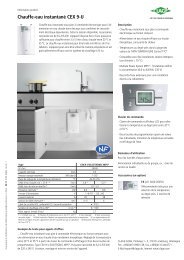
Gebrauch:<br />
Der Durchlauferhitzer erwärmt das Wasser unmittelbar während des<br />
Durchströmens auf die eingestellte Temperatur. Die Heizung schaltet<br />
automatisch bei Überschreitung der Einschaltmenge ein. Die Leuch-<br />
1 2 3<br />
te „Power“ (2) zeigt an, dass der Heizkörper eingeschaltet ist. Wenn<br />
der Durchfluss zu gering ist, leuchtet die Leuchte „Pressure“ (3).<br />
4<br />
Die Elektronik passt die Leistung automatisch der gezapften Wassermenge<br />
an, um die eingestellte Temperatur zu erreichen und nahezu<br />
konstant zu halten. Die gewünschte Auslauftemperatur kann zwi-<br />
5<br />
schen 35°C und 55°C gradgenau über die beiden Tasten (5) eingegeben<br />
und an der Digitalanzeige (4) abgelesen werden.<br />
Wenn die volle Leistung des Durchlauferhitzers nicht ausreicht, um<br />
die gezapfte Wassermenge auf die eingestellte Temperatur zu erhitzen,<br />
wird dies durch Blinken der Leuchte „Power“ (2) angezeigt.<br />
Durch Reduzierung des Warmwasserdurchflusses an der Armatur<br />
kann die Temperatur wieder erreicht werden. Wenn Sie 2 Zapfstellen<br />
angeschlossen haben, sollten Sie nur eine zur Zeit benutzen, um ausreichend<br />
Wassermenge zu zapfen.<br />
Bei hohen Einlauftemperaturen schaltet die Elektronik die Leistung<br />
automatisch aus, um zu hohe Auslauftemperaturen zu vermeiden.<br />
Dies wird durch die Leuchte „Overheat“ (1) angezeigt.<br />
Entlüften<br />
Um eine Beschädigung des Heizelementes zu vermeiden, muss es vor der ersten Inbetriebnahme<br />
entlüftet werden. Nach jeder Entleerung (z.B. nach Arbeiten in der Wasserinstallation, wegen Frostgefahr<br />
oder nach Reparaturen am Gerät) muss das Gerät vor der Wiederinbetriebnahme erneut entlüftet<br />
werden.<br />
1 Stromzufuhr durch Sicherungen abschalten.<br />
2 Danach das zugehörige Warmwasserzapfventil mehrfach öffnen und schließen, bis keine Luft mehr<br />
aus der Leitung austritt und der Durchlauferhitzer luftfrei ist (ca. 1 Minute).<br />
3 Erst dann Stromzufuhr zum Durchlauferhitzer wieder einschalten.<br />
Energiesparen<br />
Stellen Sie die gewünschte Temperatur genau am Gerät ein und öffnen Sie nur das Warmwasserzapfventil.<br />
Wenn die Wassertemperatur zu hoch ist, mischen Sie nicht kaltes Wasser zu, sondern geben am<br />
Gerät eine niedrigere Temperatur ein. Wenn Sie kaltes Wasser zumischen, wird das bereits erwärmte<br />
Wasser wieder abgekühlt und es geht wertvolle Energie verloren. Außerdem entzieht sich das in der<br />
Armatur zugemische Kaltwasser dem Regelungsbereich der Elektronik, sodass die Temperaturkonstanz<br />
nicht mehr gewährleistet ist.<br />
Pflegehinweise<br />
• Kunststoffoberflächen und Armaturen nur feucht abwischen.<br />
Keine scheuernden oder anlösenden Reinigungsmittel benutzen.<br />
• Für eine gute Wasserdarbietung sollten Sie die Perlatoren und Handbrausen regelmäßig reinigen bzw.<br />
von Zeit zu Zeit erneuern.<br />
• Lassen Sie spätestens alle drei Jahre die elektro- und wasserseitigen Bauteile durch einen anerkannten<br />
Fachhandwerksbetrieb überprüfen, um die einwandfreie Funktion und Betriebssicherheit jederzeit<br />
zu gewährleisten.<br />
Feinfilter reinigen Der Filter befindet sich im Wasseranschlussstück und sollte bei<br />
beeinträchtigter Gerätefunktion und bei einer Inspektion durch<br />
II<br />
einen Fachmann überprüft und ggf. gereinigt werden.<br />
1. Schalten Sie das Gerät spannungsfrei und drehen Sie das Absperr-<br />
9a<br />
ventil (9a) im Kaltwasseranschlussstück langsam auf Position II.<br />
2. Drehen Sie die Verschlussschraube aus dem Kaltwasseranschluss<br />
stück und nehmen Sie das Sieb heraus.<br />
I Achtung: Restwasser läuft aus!<br />
3. Das Sieb kann nun gereinigt beziehungsweise ersetzt werden.<br />
4. Nach Einbau des Siebes drehen Sie die Verschlussschraube fest.<br />
5. Drehen Sie das Absperrventil (9a) im Kaltwasseranschlussstück<br />
langsam auf (Position I).<br />
6. Entlüften Sie das Gerät, indem Sie das zugehörige Warmwasser<br />
zapfventil mehrfach langsam öffnen und schließen, bis keine Luft<br />
mehr aus der Leitung austritt.<br />
Hinweis: Bei einer Aufputz-Installation ist die Funktion des<br />
Absperrventils nicht gegeben.<br />
CLAGE GmbH<br />
Zentralkundendienst<br />
Pirolweg 1– 5<br />
D-2<strong>13</strong>37 Lüneburg<br />
Telefon: (04<strong>13</strong>1) 8901- 40<br />
Fax: (04<strong>13</strong>1) 8901- 41<br />
E-mail service @ clage.de<br />
Internet http://www.clage.de<br />
Problem mögliche Ursache Abhilfe<br />
Wasser bleibt kalt,<br />
LED-Anzeige leuchtet nicht<br />
Haussicherung hat ausgelöst Sicherung einschalten<br />
Wasser bleibt kalt, Heizelement oder Elektronik defekt “Reset” durch Aus- und Einschalten<br />
Leuchte „Power“ leuchtet der Sicherung, sonst Kundendienst<br />
möglicherweise hat STB ausgelöst Hinweis für den Fachmann:<br />
STB einschalten / bei wiederholtem<br />
Auslösen Kundendienst<br />
Wasser bleibt kalt,<br />
Leuchte „Pressure“ leuchtet<br />
Durchfluss zu schwach Fließwasserdruck erhöhen<br />
Warmwasserdurchfluss Systembedingt Prüfen anhand technischer Daten<br />
ist zu schwach<br />
Schmutz oder Kalk in Armatur Armatur / Handbrause reinigen<br />
Änderungen vorbehalten.<br />
9120 2520 GP-BA 02.2007 3<br />
Filter verschmutzt oder verkalkt Filter reinigen oder erneuern<br />
falsche Armaturen CLAGE Handbrause / Perlator<br />
Wasser wird nicht heiß genug Elektronik Sicherung aus- und einschalten<br />
Wasserdurchfluss zu groß (Winter?) Wasserdurchfluss reduzieren<br />
Heizelement defekt Kundendienst<br />
Temperatur und Druck schwanken Kaltwasser wird zugemischt Nur Warmwasser gradgenau zapfen<br />
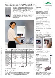
Geräteübersicht und Ersatzteile<br />
Bei Bestellungen stets Gerätetyp, Nennleistung und Seriennummer angeben!<br />
4 5<br />
3<br />
2<br />
1<br />
Selbsthilfe bei Problemen<br />
Sollte es zu Störungen kommen, versuchen Sie bitte, das Problem<br />
zunächst mit Hilfe der Tabelle zu lösen.Wenn sich das Problem nicht<br />
beheben lässt, wenden Sie sich bitte an den CLAGE Zentralkundendienst.<br />
Dort hilft man Ihnen weiter oder nennt Ihnen einen Kundendienst-Vertragspartner<br />
in Ihrer Nähe. Halten Sie die Typenbezeichnung<br />
und Seriennummer des Gerätes lt. Typenschild bereit.<br />
Reparaturen nur von anerkannten Fachhandwerksbetrieben<br />
ausführen lassen!<br />
6<br />
7<br />
8<br />
9<br />
10<br />
<strong>11</strong><br />
Pos. Bezeichnung<br />
1 Schwenknippel<br />
2 Heizelement<br />
3 Anzeigenplatine<br />
4 Sicherheitstemp.-begrenzer (STB)<br />
5 Gerätehaube<br />
6 Anschlussklemme<br />
7 Elektronik<br />
8 Durchflussgeber<br />
9 Kaltwassereinlaufstück mit Filter<br />
10 Gummitülle<br />
<strong>11</strong> Kleinteilesortiment<br />
mit Dichtungen, Filter,<br />
Schrauben und Mikroschalter<br />
(für Ersatzteilbedarf, gehört<br />
nicht zum Lieferumfang)<br />
<strong>CBX</strong> <strong>11</strong>, <strong>CBX</strong> <strong>13</strong><br />
<strong>GB</strong><br />
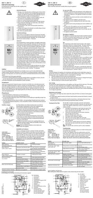
<strong>Operating</strong> <strong>Instructions</strong><br />
Please read these instructions carefully before using the appliance!<br />
For your own safety<br />
• Installation, commissioning and maintenance of this appliance may<br />
only be undertaken by an authorized professional who will then be<br />
responsible for adherence to the applicable standards and installation<br />
regulations.<br />
• The appliance may only be used when correctly installed and in perfect<br />
working order!<br />
• The appliance must be installed in a frost-free room!<br />
• The appliance must be completely filled with water before being<br />
switched on!<br />
• The appliance and its wiring and piping must not be modified in any<br />
way!<br />
• The front cover of the appliance must never be opened before disconnecting<br />
the appliance from the mains power supply!<br />
• Be careful! When the appliance has been in use for some time, the<br />
fittings may be very hot!<br />
• The appliance must be earthed!<br />
Description of appliance<br />
The appliance is a pressure-type electronically controlled instantaneous<br />
heater for decentral water heating at one or two taps situated<br />
in close proximity to one another, e.g. kitchen sink or shower.<br />
Technical specifications ➞ overleaf!<br />
Use<br />
The instantaneous water heater heats the water to the required<br />
temperature directly as it streams through. The heater switches on<br />
1 2 3<br />
automatically when the threshold flow rate is exceeded. The<br />
"Power" indicator (2) lights up when the heater is switched on.<br />
4<br />
The "Pressure" indicator (3) lights up when the flow rate is too low.<br />
The power is automatically adjusted by the electronics in line with<br />
the water flow rate in order to obtain the set temperature and keep<br />
5<br />
it virtually constant. The required temperature can be set to within<br />
one degree between 35 °C and 55 °C via the two buttons (5) and<br />
can be read off on the digital display (4).<br />
If the full power of the instantaneous heater is not sufficient to heat<br />
the water to the required temperature, this is indicated by the flashing<br />
"Power" indicator (2). The temperature can be restored by<br />
reducing the hot water flow rate at the tap. If the heater supplies<br />
two outlets, the water from the unit will be shared between the<br />
outlets. You should therefore only use one outlet at a time in order<br />
to obtain a sufficient flow.<br />
At high feed temperatures, the power is automatically switched off<br />
by the electronics in order to avoid producing excessively hot water.<br />
This is indicated by the "Overheat" lamp (1).<br />
Venting<br />
To prevent damage to the appliance, the instantaneous water heater must be vented before using it for<br />
the first time. Each time it is emptied (e.g. after work on the plumbing system, if there is a risk of frost or<br />
following repair work), the appliance must be re-vented before it is used again.<br />
1 Disconnect appliance from the mains by removing the fuses.<br />
2 Next, open and close the hot water tap valve several times until no more air emerges from the pipe<br />
and all air has been eliminated from the water heater (approx. 1 minute).<br />
3 Only then should you re-connect the power supply to the unit.<br />
Subject to alteration without notice.<br />
9120 2520 GP-BA 02.2007 3<br />
Save energy<br />
Set precisely the required temperature on the appliance and only open the hot water tap. If the water<br />
is too hot, set a lower temperature on the appliance instead of adding cold water.<br />
If you add cold water, the heated water is cooled again and valuable energy will be lost. Moreover,<br />
the cold water added in the fitting cannot be controlled by the electronics and a constant temperature<br />
can no longer be guaranteed.<br />
Maintenance and cleaning<br />
• Plastic surfaces and fittings may only be wiped with a damp cloth. Never use abrasive cleaning agents<br />
or solvents.<br />
• For a good water supply, the aerators and shower heads should be unscrewed and cleaned or renewed<br />
at regular intervals.<br />
• The electrical and plumbing components should be inspected by an authorized professional at least<br />
every three years to ensure proper functioning and operational safety at all times.<br />
Cleaning the fine filter<br />
The fine filter is located in the water connection and should be<br />
examined by an expert and cleaned if necessary not only when operation<br />
of the appliance deteriorates, but also in conjunction with<br />
regular servicing.<br />
1. Deenergise the instantaneous water heater by means of the<br />
house fuses and close the shut-off valve (9a) in the cold<br />
water connection piece (position II).<br />
2. Unscrew the screw plug from the cold water connection<br />
piece and take out the strainer.<br />
Attention: Residual water comes out!<br />
3. The strainer can be cleaned or replaced.<br />
4. After fixtur of the strainer tighten the screw plug.<br />
5. Slowly open the shut-off valvein the cold water connection<br />
piece (position I).<br />
6. Vent the unit by carefully opening and closing the affiliated<br />
warm water tap valve several times until air no longer emerges<br />
from the pipe.<br />
Note: The shut-off valve cannot be used for surface installation.<br />
Troubleshooting<br />
If you experience a malfunction, please try to rectify the fault yourself<br />
first with the help of this table.<br />
If a fault in your appliance cannot be rectified with the aid of this<br />
table, please contact CLAGE who will either assist you directly or put<br />
you in touch with a customer service contract partner in your area.<br />
Always specify the appliance model and serial number, please!<br />
Repairs may only be carried out by authorized professionals.<br />
Problem Possible Cause Solution<br />
LED remains off<br />
water remains cold<br />
Circuit breaker tripped Have the fault rectified and reset<br />
The pilot lamp „Power“ lights, Heating element or electronics faulty Reset fuse,<br />
water remains cold contact customer service<br />
Safety thermal cut-out tripped Reset. In case of repeated trips<br />
contact customer service<br />
The pilot lamp „Pressure“ lights,<br />
water remains cold<br />
Flow rate too low Increase flow pressure<br />
Water flows lower as expected Depends on the heater Check technical specifications<br />
Outlet fitting dirty or calcified Clean tap fitting or shower head<br />
Filter dirty or calcified Clean or renew the filter<br />
Tap not suitable Use CLAGE shower head or aerator<br />
The hot water is not hot enough Electronic board Reset fuse<br />
Flow rate is too high (winter?) Reduce the water flow slightly<br />
Heating element defect Contact customer service<br />
Temperature and pressure vary Cold water is being added Only hot water can be delivered to<br />
within one degree<br />
Layout of appliance and spare parts<br />
When ordering, please always specify the appliance model, nominal rating and serial number!<br />
4 5<br />
3<br />
2<br />
1<br />
9a<br />
CLAGE GmbH<br />
Customer Service<br />
Pirolweg 1– 5<br />
D-2<strong>13</strong>37 Lüneburg<br />
Fon: +49 4<strong>13</strong>1 8901- 40<br />
Fax: +49 4<strong>13</strong>1 8901- 41<br />
E-mail service @ clage.de<br />
Internet http://www.clage.de<br />
II<br />
I<br />
6<br />
7<br />
8<br />
9<br />
10<br />
<strong>11</strong><br />
Pos. Description<br />
1 Swivel nipple<br />
2 Heating element<br />
3 Display panel<br />
4 Safety thermal cut-out (STB)<br />
5 Appliance front cover<br />
6 Connection terminal<br />
7 Electronic board<br />
8 Flow sensor<br />
9 Cold water inlet<br />
10 Cable seal<br />
<strong>11</strong> Set of small spareparts<br />
washers, filter,<br />
screws and microswitch<br />
(for spare requirements,<br />
not included in delivery)
BA_<strong>CBX</strong>_D-<strong>GB</strong>-2007.qxd 16.02.2007 15:09 Uhr Seite 2<br />
<strong>CBX</strong> <strong>11</strong>, <strong>CBX</strong> <strong>13</strong><br />
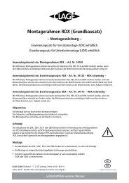
Montageanweisung für den Fachmann<br />
Technische Daten:<br />
9a<br />
II<br />
I<br />
Zu beachten sind:<br />
• Die gesetzlichen Vorschriften des jeweiligen Landes und die<br />
Bestimmungen des örtlichen Elektrizitäts- und<br />
Wasserversorgungsunternehmens.<br />
• Angaben auf dem Typenschild.<br />
• Technische Daten.<br />
Montageort:<br />
• Der Montageort muss stets frostfrei sein.<br />
• Das Gerät entspricht der Schutzart IP25 und darf im<br />
Schutzbereich 1 nach VDE 0100 Teil 701 installiert werden.<br />
• Zur Vermeidung von Wärmeverlusten sollte die Entfernung vom<br />
Gerät zur Zapfstelle möglichst gering sein (< 2 m).<br />
• Eine optimale Funktion ist bei einem Fließwasserdruck von ≥ 3 bar<br />
gewährleistet. Der Netzdruck darf 10 bar nicht überschreiten.<br />
Gerät installieren:<br />
1 Wasserzuleitungen gründlich spülen und für die Installation<br />
absperren.<br />
2 Zum Öffnen des Gehäuses die Sicherungsschraube hinter<br />
der kleinen Klappe herausdrehen.<br />
3 Die gewünschten Bohrlöcher und Kabeleinführungsöffnungen<br />
bestimmen und ausbrechen. Mit dem Gerät die Bohrlöcher<br />
anzeichnen und mit einem 6 mm-Bohrer bohren.<br />
4 Die mitgelieferte Gummitülle einsetzen und das Anschlusskabel<br />
durchführen. Bei Verwendung einer flexiblen Netzleitung muss die<br />
Leitung mit der Zugentlastung gesichert werden.<br />
5 Das Gerät mit beiliegenden Dübeln und Schrauben festschrauben.<br />
6 Gerät entsprechend einer der obenstehenden Skizzen installieren.<br />
Kaltwassereinlauf und Warmwasserauslauf sind durch Pfeile<br />
gekennzeichnet.<br />
7 Die Wasseranschlüsse sind sowohl für die Unterputz- als auch für<br />
die Aufputzinstallation geeignet. Dichten Sie diese zur Verschraubung<br />
in die Wandanschlüsse mit geringem Materialeinsatz sorgfältig<br />
ab.<br />
8 Bei Aufputzinstallation die Haube an den vorgesehenen Stellen<br />
sauber ausbrechen.<br />
9 Öffnen Sie die Wasserzuleitung und drehen Sie ggf. das Absperrventil<br />
(9a) im Kaltwasseranschlussstück langsam auf (Pos.I).<br />
Prüfen Sie alle Verbindungen auf Dichtigkeit.<br />
10 Danach mehrfach das zugehörige Warmwasserzapfventil öffnen<br />
und schließen bis keine Luft mehr aus der Leitung austritt.<br />
Elektro-Anschluss:<br />
Der Durchlauferhitzer ist ein Gerät der Schutzklasse I<br />
und muss an den Schutzleiter angeschlossen werden!<br />
1 Vor dem elektrischen Anschluss die Zuleitung zum Gerät<br />
spannungsfrei schalten!<br />
• Das Gerät muss mit einer zulässigen Netzanschlussleitung oder<br />
mit direktem Festanschluss angeschlossen werden. Installationsseitig<br />
ist eine allpolige Trennvorrichtung (z.B. über Sicherungen)<br />
mit einer Kontaktöffnungsweite von ≥ 3mm pro Pol vorzusehen.<br />
• Der Querschnitt der Zuleitung muss der Leistung entsprechend<br />
dimensioniert sein.<br />
• Zur Absicherung des Gerätes ist ein Sicherungselement für<br />
Leitungsschutz mit einem dem Gerätenennstrom angepassten<br />
Auslösestrom zu montieren.<br />
2 Das Anschlusskabel ist mit der Gummitülle abzudichten und mit<br />
den Leitungen sowie dem Schutzleiter an die entsprechend<br />
beschriftete Anschlussklemme sorgfältig anzuschließen.<br />
• Bei Bedarf kann die Anschlussklemme in den unteren Gerätebereich<br />
verlegt werden.<br />
• Die Zugentlastung kann verwendet werden. Das Anschlusskabel<br />
darf nicht auf Zug beansprucht werden, wenn die Zugentlastung<br />
nicht verwendet wird.<br />
3 Haube aufsetzen. Mit der Befestigungsschraube sichern.<br />
4 Gerät durch Wasserfüllung vollständig entlüften, Sicherung<br />
wieder einschalten und Gerät in Betrieb nehmen.<br />
5 Erklären Sie dem Benutzer den Gebrauch des Durchlauferhitzers,<br />
und falten Sie diese Anleitung, um sie hinter der Frontklappe<br />
aufzubewahren.<br />
Typ: <strong>CBX</strong> <strong>11</strong> <strong>CBX</strong> <strong>13</strong><br />
Inhalt: 0,2 Liter<br />
Bauart: geschlossen, Nennüberdruck: 10 bar (1 MPa)<br />
Heizsystem: Blankdraht<br />
Einsatzbereich (spez. Wasserwiderstand): ≥ 1.100 Ω cm bei 15°C<br />
Nennspannung (50 / 60 Hz): 3/PE ~ 400 V<br />
Nennleistung: <strong>11</strong> kW <strong>13</strong>,5 kW<br />
Nennstrom: 16 A 19,5 A<br />
Erforderlicher Leiterquerschnitt: 4 x 2,5 mm2 4 x 4,0 mm2 Maximale Temperaturerhöhung<br />
bei Nennleistung und Durchfluss 4 l/min: 39 °C 1 48 °C 1<br />
Durchfluss 6 l/min: 26 °C 1 32 °C 1<br />
Durchfluss 8 l/min: 19 °C 1 24 °C 1<br />
Durchfluss 10 l/min: 16 °C 1 19 °C 1<br />
1 + Kaltwassertemperatur = maximale Warmwassertemperatur ≤ 55<br />
°C<br />
Einschaltwassermenge: 2 l/min<br />
Temperaturvoreinstellung: 35 – 55 °C<br />
Geeignet für Kaltwasser bis ca.: 30 °C<br />
Wasseranschluss: G 1/2“ Auf- oder Unterputz<br />
Leergewicht und Abmessungen (H x B x T): ca. 2,2 kg / 33 x 21 x 9 cm<br />
Schutzklasse und Schutzart nach VDE: 1 / IP25<br />
Sicherheitszeichen: siehe Typenschild<br />
D<br />
geschlossene<br />
Unterputzinstallation<br />
<strong>CBX</strong> <strong>11</strong>, <strong>CBX</strong> <strong>13</strong><br />
<strong>GB</strong><br />
Installation instructions for the authorized technician<br />
9a<br />
Technical specifications:<br />
II<br />
I<br />
The following must be observed:<br />
• The statutory regulations of the respective country, as well as<br />
those of the local electricity and water supply companies.<br />
• The specifications on the rating plate and the technical specifications.<br />
Installation site<br />
• The installation site must be free from frost at all times.<br />
• The appliance complies with protection type IP25 and may be<br />
installed in zone 1 acc. IEC<br />
• In order to avoid thermal losses, the distance between the heater<br />
and the tapping point should be as small as possible (< 2 m).<br />
• Best performance is guaranteed at a flow pressure of ≥ 3 bar,<br />
avoiding pressures exceeding 10 bar.<br />
Installing the appliance:<br />
1 Rinse water supply pipes thoroughly and turn off for installation.<br />
2 Remove the front cover by unscrewing the locking screw behind<br />
the small lid.<br />
3 Locate and break out the required holes and cable inlets. Mark<br />
the drilling holes with the appliance and drill them with a 6 mm<br />
bit.<br />
4 Fit the rubber grommet supplied and insert the connecting lead.<br />
The lead must be secured with the able clamp when using a flexible<br />
power cord.<br />
5 Screw the appliance into position using the enclosed raw plugs<br />
and screws.<br />
Closed<br />
flush-mounted installation<br />
6 Install the appliance as shown in the principal examples above.<br />
The inlet and outlet are marked with arrows.<br />
7 The water connections are designed for surface-mounted or flushmounted<br />
installation. They must be carefully sealed with a little<br />
P.T.F.E. Tape when screwed into the wall connections.<br />
8 The front cover must be neatly broken at the designated points<br />
when installed on the wall.<br />
9 Turn on the water supply and slowly open the shutoff valve (9a)<br />
in the cold-water connection (position I) if necessary.<br />
Check all connections for leaks.<br />
10 Next, open and close the hot water tap several times until no<br />
more air emerges from the line and all air has been eliminated<br />
from the heater.<br />
Electrical connection:<br />
The instantaneous water heater is an appliance<br />
of protection class I and must be connected to the<br />
protective earth conductor!<br />
1 Check that the power supply is switched off prior to the electrical<br />
connection!<br />
• The appliance must be connected to the supply by means of permanent<br />
wiring through suitable isolation having a contact separation<br />
of at least 3 mm in all poles.<br />
• The cross sectional area of the connection cable must be in accordance<br />
with the power rating.<br />
• To protect the appliance, a fuse element must be fitted with a<br />
tripping current commensurate with the nominal current of the<br />
appliance.<br />
2 The connection cable should be sealed with the cable seal and<br />
carefully connected to the terminal block using leads as well as<br />
the earth conductor.<br />
• The connecting terminal can be transferred to the bottom of the<br />
appliance if necessary.<br />
• The cable clamp can be used. The connecting cable must not be<br />
strained when the cable clamp is not used.<br />
3 Fit the front cover. Secure the front cover with the fastening screw.<br />
4 Fill the appliance with water completely, switch on the power<br />
supply to the appliance.<br />
5 Explain the use of the instantaneous water heater to the<br />
user and fold these instructions so that they can be stored<br />
behind the front panel.<br />
Type: <strong>CBX</strong> <strong>11</strong> <strong>CBX</strong> <strong>13</strong><br />
Capacity: 0.2 litre<br />
Pressure-type, rating pressure: 10 bar (1 MPa)<br />
Heating system: Bare element<br />
Area of use (spec. water resistance): ≥ 1.100 ohm.cm at 15°C<br />
Rated voltage (50 / 60 Hz): 3/PE ~ 380..400 V<br />
Nominal rating: 9.9 kW / 380 V 12.2 kW / 380 V<br />
Rated current at 380 V: 15.1 A 18.6 A<br />
Required conductor cross-section: 4 x 2.5 mm 2 4 x 4.0 mm 2<br />
Maximum temperature increase<br />
at nominal rating and flow rate of 4 l/min: 35 °C 1 44 °C 1<br />
flow rate of 6 l/min: 24 °C 1 29 °C 1<br />
flow rate of 8 l/min: 18 °C 1 22 °C 1<br />
flow rate of 10 l/min: 14 °C 1 17 °C 1<br />
Threshold flow rate:<br />
1 + cold water temperature = maximum hot water temperature ≤ 60 °C<br />
2 l/min<br />
Temperature presetting: 35 – 55 °C<br />
Useful for cold water up to: 30 °C<br />
Water connection: 1/2“ B.S.P. surface-mounted or flush-mounted<br />
Net weight and dimensions (H x W x D): 2.2 kg / 33 x 21 x 9 cm<br />
Protection class and type of protection to VDE 1 / IP25<br />
Safety mark: see rating plate