CBX 11, CBX 13 Operating Instructions 1 2 4 5 3 GB CBX 11, CBX ...
CBX 11, CBX 13 Operating Instructions 1 2 4 5 3 GB CBX 11, CBX ...
CBX 11, CBX 13 Operating Instructions 1 2 4 5 3 GB CBX 11, CBX ...

You also want an ePaper? Increase the reach of your titles
YUMPU automatically turns print PDFs into web optimized ePapers that Google loves.
BA_<strong>CBX</strong>_D-<strong>GB</strong>-2007.qxd 16.02.2007 15:09 Uhr Seite 2<br />
<strong>CBX</strong> <strong>11</strong>, <strong>CBX</strong> <strong>13</strong><br />
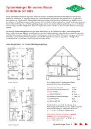
Montageanweisung für den Fachmann<br />
Technische Daten:<br />
9a<br />
II<br />
I<br />
Zu beachten sind:<br />
• Die gesetzlichen Vorschriften des jeweiligen Landes und die<br />
Bestimmungen des örtlichen Elektrizitäts- und<br />
Wasserversorgungsunternehmens.<br />
• Angaben auf dem Typenschild.<br />
• Technische Daten.<br />
Montageort:<br />
• Der Montageort muss stets frostfrei sein.<br />
• Das Gerät entspricht der Schutzart IP25 und darf im<br />
Schutzbereich 1 nach VDE 0100 Teil 701 installiert werden.<br />
• Zur Vermeidung von Wärmeverlusten sollte die Entfernung vom<br />
Gerät zur Zapfstelle möglichst gering sein (< 2 m).<br />
• Eine optimale Funktion ist bei einem Fließwasserdruck von ≥ 3 bar<br />
gewährleistet. Der Netzdruck darf 10 bar nicht überschreiten.<br />
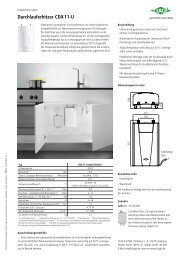
Gerät installieren:<br />
1 Wasserzuleitungen gründlich spülen und für die Installation<br />
absperren.<br />
2 Zum Öffnen des Gehäuses die Sicherungsschraube hinter<br />
der kleinen Klappe herausdrehen.<br />
3 Die gewünschten Bohrlöcher und Kabeleinführungsöffnungen<br />
bestimmen und ausbrechen. Mit dem Gerät die Bohrlöcher<br />
anzeichnen und mit einem 6 mm-Bohrer bohren.<br />
4 Die mitgelieferte Gummitülle einsetzen und das Anschlusskabel<br />
durchführen. Bei Verwendung einer flexiblen Netzleitung muss die<br />
Leitung mit der Zugentlastung gesichert werden.<br />
5 Das Gerät mit beiliegenden Dübeln und Schrauben festschrauben.<br />
6 Gerät entsprechend einer der obenstehenden Skizzen installieren.<br />
Kaltwassereinlauf und Warmwasserauslauf sind durch Pfeile<br />
gekennzeichnet.<br />
7 Die Wasseranschlüsse sind sowohl für die Unterputz- als auch für<br />
die Aufputzinstallation geeignet. Dichten Sie diese zur Verschraubung<br />
in die Wandanschlüsse mit geringem Materialeinsatz sorgfältig<br />
ab.<br />
8 Bei Aufputzinstallation die Haube an den vorgesehenen Stellen<br />
sauber ausbrechen.<br />
9 Öffnen Sie die Wasserzuleitung und drehen Sie ggf. das Absperrventil<br />
(9a) im Kaltwasseranschlussstück langsam auf (Pos.I).<br />
Prüfen Sie alle Verbindungen auf Dichtigkeit.<br />
10 Danach mehrfach das zugehörige Warmwasserzapfventil öffnen<br />
und schließen bis keine Luft mehr aus der Leitung austritt.<br />
Elektro-Anschluss:<br />
Der Durchlauferhitzer ist ein Gerät der Schutzklasse I<br />
und muss an den Schutzleiter angeschlossen werden!<br />
1 Vor dem elektrischen Anschluss die Zuleitung zum Gerät<br />
spannungsfrei schalten!<br />
• Das Gerät muss mit einer zulässigen Netzanschlussleitung oder<br />
mit direktem Festanschluss angeschlossen werden. Installationsseitig<br />
ist eine allpolige Trennvorrichtung (z.B. über Sicherungen)<br />
mit einer Kontaktöffnungsweite von ≥ 3mm pro Pol vorzusehen.<br />
• Der Querschnitt der Zuleitung muss der Leistung entsprechend<br />
dimensioniert sein.<br />
• Zur Absicherung des Gerätes ist ein Sicherungselement für<br />
Leitungsschutz mit einem dem Gerätenennstrom angepassten<br />
Auslösestrom zu montieren.<br />
2 Das Anschlusskabel ist mit der Gummitülle abzudichten und mit<br />
den Leitungen sowie dem Schutzleiter an die entsprechend<br />
beschriftete Anschlussklemme sorgfältig anzuschließen.<br />
• Bei Bedarf kann die Anschlussklemme in den unteren Gerätebereich<br />
verlegt werden.<br />
• Die Zugentlastung kann verwendet werden. Das Anschlusskabel<br />
darf nicht auf Zug beansprucht werden, wenn die Zugentlastung<br />
nicht verwendet wird.<br />
3 Haube aufsetzen. Mit der Befestigungsschraube sichern.<br />
4 Gerät durch Wasserfüllung vollständig entlüften, Sicherung<br />
wieder einschalten und Gerät in Betrieb nehmen.<br />
5 Erklären Sie dem Benutzer den Gebrauch des Durchlauferhitzers,<br />
und falten Sie diese Anleitung, um sie hinter der Frontklappe<br />
aufzubewahren.<br />
Typ: <strong>CBX</strong> <strong>11</strong> <strong>CBX</strong> <strong>13</strong><br />
Inhalt: 0,2 Liter<br />
Bauart: geschlossen, Nennüberdruck: 10 bar (1 MPa)<br />
Heizsystem: Blankdraht<br />
Einsatzbereich (spez. Wasserwiderstand): ≥ 1.100 Ω cm bei 15°C<br />
Nennspannung (50 / 60 Hz): 3/PE ~ 400 V<br />
Nennleistung: <strong>11</strong> kW <strong>13</strong>,5 kW<br />
Nennstrom: 16 A 19,5 A<br />
Erforderlicher Leiterquerschnitt: 4 x 2,5 mm2 4 x 4,0 mm2 Maximale Temperaturerhöhung<br />
bei Nennleistung und Durchfluss 4 l/min: 39 °C 1 48 °C 1<br />
Durchfluss 6 l/min: 26 °C 1 32 °C 1<br />
Durchfluss 8 l/min: 19 °C 1 24 °C 1<br />
Durchfluss 10 l/min: 16 °C 1 19 °C 1<br />
1 + Kaltwassertemperatur = maximale Warmwassertemperatur ≤ 55<br />
°C<br />
Einschaltwassermenge: 2 l/min<br />
Temperaturvoreinstellung: 35 – 55 °C<br />
Geeignet für Kaltwasser bis ca.: 30 °C<br />
Wasseranschluss: G 1/2“ Auf- oder Unterputz<br />
Leergewicht und Abmessungen (H x B x T): ca. 2,2 kg / 33 x 21 x 9 cm<br />
Schutzklasse und Schutzart nach VDE: 1 / IP25<br />
Sicherheitszeichen: siehe Typenschild<br />
D<br />
geschlossene<br />
Unterputzinstallation<br />
<strong>CBX</strong> <strong>11</strong>, <strong>CBX</strong> <strong>13</strong><br />
<strong>GB</strong><br />
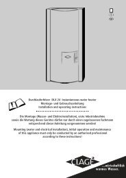
Installation instructions for the authorized technician<br />
9a<br />
Technical specifications:<br />
II<br />
I<br />
The following must be observed:<br />
• The statutory regulations of the respective country, as well as<br />
those of the local electricity and water supply companies.<br />
• The specifications on the rating plate and the technical specifications.<br />
Installation site<br />
• The installation site must be free from frost at all times.<br />
• The appliance complies with protection type IP25 and may be<br />
installed in zone 1 acc. IEC<br />
• In order to avoid thermal losses, the distance between the heater<br />
and the tapping point should be as small as possible (< 2 m).<br />
• Best performance is guaranteed at a flow pressure of ≥ 3 bar,<br />
avoiding pressures exceeding 10 bar.<br />
Installing the appliance:<br />
1 Rinse water supply pipes thoroughly and turn off for installation.<br />
2 Remove the front cover by unscrewing the locking screw behind<br />
the small lid.<br />
3 Locate and break out the required holes and cable inlets. Mark<br />
the drilling holes with the appliance and drill them with a 6 mm<br />
bit.<br />
4 Fit the rubber grommet supplied and insert the connecting lead.<br />
The lead must be secured with the able clamp when using a flexible<br />
power cord.<br />
5 Screw the appliance into position using the enclosed raw plugs<br />
and screws.<br />
Closed<br />
flush-mounted installation<br />
6 Install the appliance as shown in the principal examples above.<br />
The inlet and outlet are marked with arrows.<br />
7 The water connections are designed for surface-mounted or flushmounted<br />
installation. They must be carefully sealed with a little<br />
P.T.F.E. Tape when screwed into the wall connections.<br />
8 The front cover must be neatly broken at the designated points<br />
when installed on the wall.<br />
9 Turn on the water supply and slowly open the shutoff valve (9a)<br />
in the cold-water connection (position I) if necessary.<br />
Check all connections for leaks.<br />
10 Next, open and close the hot water tap several times until no<br />
more air emerges from the line and all air has been eliminated<br />
from the heater.<br />
Electrical connection:<br />
The instantaneous water heater is an appliance<br />
of protection class I and must be connected to the<br />
protective earth conductor!<br />
1 Check that the power supply is switched off prior to the electrical<br />
connection!<br />
• The appliance must be connected to the supply by means of permanent<br />
wiring through suitable isolation having a contact separation<br />
of at least 3 mm in all poles.<br />
• The cross sectional area of the connection cable must be in accordance<br />
with the power rating.<br />
• To protect the appliance, a fuse element must be fitted with a<br />
tripping current commensurate with the nominal current of the<br />
appliance.<br />
2 The connection cable should be sealed with the cable seal and<br />
carefully connected to the terminal block using leads as well as<br />
the earth conductor.<br />
• The connecting terminal can be transferred to the bottom of the<br />
appliance if necessary.<br />
• The cable clamp can be used. The connecting cable must not be<br />
strained when the cable clamp is not used.<br />
3 Fit the front cover. Secure the front cover with the fastening screw.<br />
4 Fill the appliance with water completely, switch on the power<br />
supply to the appliance.<br />
5 Explain the use of the instantaneous water heater to the<br />
user and fold these instructions so that they can be stored<br />
behind the front panel.<br />
Type: <strong>CBX</strong> <strong>11</strong> <strong>CBX</strong> <strong>13</strong><br />
Capacity: 0.2 litre<br />
Pressure-type, rating pressure: 10 bar (1 MPa)<br />
Heating system: Bare element<br />
Area of use (spec. water resistance): ≥ 1.100 ohm.cm at 15°C<br />
Rated voltage (50 / 60 Hz): 3/PE ~ 380..400 V<br />
Nominal rating: 9.9 kW / 380 V 12.2 kW / 380 V<br />
Rated current at 380 V: 15.1 A 18.6 A<br />
Required conductor cross-section: 4 x 2.5 mm 2 4 x 4.0 mm 2<br />
Maximum temperature increase<br />
at nominal rating and flow rate of 4 l/min: 35 °C 1 44 °C 1<br />
flow rate of 6 l/min: 24 °C 1 29 °C 1<br />
flow rate of 8 l/min: 18 °C 1 22 °C 1<br />
flow rate of 10 l/min: 14 °C 1 17 °C 1<br />
Threshold flow rate:<br />
1 + cold water temperature = maximum hot water temperature ≤ 60 °C<br />
2 l/min<br />
Temperature presetting: 35 – 55 °C<br />
Useful for cold water up to: 30 °C<br />
Water connection: 1/2“ B.S.P. surface-mounted or flush-mounted<br />
Net weight and dimensions (H x W x D): 2.2 kg / 33 x 21 x 9 cm<br />
Protection class and type of protection to VDE 1 / IP25<br />
Safety mark: see rating plate