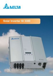
Solar Inverter SI 3300 - ET SolarPower GmbH
Solar Inverter SI 3300 - ET SolarPower GmbH
Solar Inverter SI 3300 - ET SolarPower GmbH

Erfolgreiche ePaper selbst erstellen
Machen Sie aus Ihren PDF Publikationen ein blätterbares Flipbook mit unserer einzigartigen Google optimierten e-Paper Software.
4.1 Data evaluation and communication<br />
The integrated data display, processing and communication of the device enables easy operation<br />
of the solar inverter. Monitoring of the operational status and signaling of operational failures are<br />
capable of being called up over the device display. The data interfaces enable the downloading of<br />
data which can be evaluated with the aid of a PC system and thus guarantees continuous recording<br />
of operating data.<br />
The best way of accessing this functionality is via the available accessories (e.g. WEB´log);<br />
comprehensive and seamless solar inverter monitoring is ensured.<br />
The read-out of the data over the integrated interface and the display is possible only in solar operation.<br />
4.2 Technical structure of the solar inverter<br />
A potential isolation of the solar inverter from the mains network is achieved through a radio frequency<br />
converter with integrated transformer. The photovoltaic voltage is adjusted so that the maximum<br />
power output of the PV modules is also achieved with different solar irradiation levels and<br />
temperatures (MPP-Tracking).<br />
The MPP range of the solar inverter is between 150 V and 450 V. This facilitates the use of PV<br />
modules by a variety of manufacturers. Measures must be taken to ensure that the maximum noload<br />
voltage of 540 V is never exceeded. Please note that the maximum no-load voltage will occur<br />
at the lowest temperatures anticipated. You will find more detailed information about temperature<br />
dependency in the data sheet for the PV modules.<br />
The device’s power consumption is kept to a minimum.<br />
The high-quality aluminum casing corresponds to Protection Type IP65 (water-jet-proof and dustproof)<br />
and is protected against weathering processes by surface refinement. The cooling characteristic<br />
profile is designed so that operation of the inverter is possible with ambient temperatures<br />
from -25°C to +70°C.<br />
A cooling characteristic profile is used for the removal of the power dissipation caused through<br />
the voltage conversion. An internal temperature control protects the device against too high temperatures<br />
in the interior of the solar inverter. In case of high ambient temperatures, the maximum<br />
transferable power is limited (see diagram under 6.5).<br />
The solar inverter is controlled by microcontrollers, which also implement interface communication<br />
and the displays of values and messages on the display.<br />
Two independent and redundant microcontrollers control the monitoring of the network, which is<br />
consistent with the feed-in directives of VDEW and DIN 0126-1-1 (ENS). This enables an installation<br />
of the solar inverter in the in-house mains network.<br />
Operator protection requirements are met by electrically isolating the mains from the PV module.<br />
The electrical isolation between the mains and the PV module is equivalent to basic insulation.<br />
Maximum operator protection is ensured by reinforced isolation between the mains, PV modules<br />
and accessible interfaces (display, RS485 interface and fan port). Relevant standards concerning<br />
electromagnetic compatibility (EMC) and safety are fulfilled.<br />
The solar inverter is functional in network parallel operation exclusively. An automatically-acting<br />
isolation point, which was accepted by a certification agency, guarantees secure disconnection in<br />
case of circuit isolation or interruptions in power supply and avoids isolated operation.