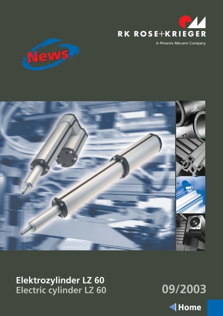
Elektrozylinder LZ 60 - AVS Phoenix Mecano
Elektrozylinder LZ 60 - AVS Phoenix Mecano
Elektrozylinder LZ 60 - AVS Phoenix Mecano

Erfolgreiche ePaper selbst erstellen
Machen Sie aus Ihren PDF Publikationen ein blätterbares Flipbook mit unserer einzigartigen Google optimierten e-Paper Software.
<strong>Elektrozylinder</strong> <strong>LZ</strong> <strong>60</strong><br />
Electric cylinder <strong>LZ</strong> <strong>60</strong> 09/2003<br />
Home
<strong>Elektrozylinder</strong> <strong>LZ</strong> <strong>60</strong><br />
Electric cylinder <strong>LZ</strong> <strong>60</strong><br />
Nuten für Zubehörbefestigung und Magnetschalter<br />
durch Abdeckprofil verschlossen<br />
Cover profiles for the accessories fixation<br />
slots and the magnetic switch<br />
<strong>LZ</strong> <strong>60</strong> S<br />
<strong>LZ</strong> <strong>60</strong> P<br />
Beschreibung<br />
Mit der <strong>LZ</strong> <strong>60</strong>-Baureihe präsentiert RK Rose+Krieger<br />
einen komplett neuen <strong>Elektrozylinder</strong>, der sich durch<br />
eine große Funktionalität, eine hohe Leistungsdichte<br />
und ein ansprechendes Design auszeichnet. Mit diesen<br />
Eigenschaften eignet sich der Zylinder sowohl für<br />
Industrie-Anwendungen als auch für Einsätze in<br />
Medizin- und Fitnessgeräten.<br />
Der Antrieb ist in schlanker Stabform (<strong>LZ</strong> <strong>60</strong> S) oder mit<br />
parallel montiertem Motor (<strong>LZ</strong> <strong>60</strong> P) erhältlich. Die<br />
Variante <strong>LZ</strong> <strong>60</strong> P eignet sich besonders für Anwendungsbereiche,<br />
in denen eine besonders kompakte<br />
Bauweise gefordert ist. Als Zubehör sind Magnetschalter<br />
erhältlich.<br />
Die Anschlussbefestigung des <strong>Elektrozylinder</strong>s ist<br />
kompatibel zu handelsüblichen Pneumatik- und<br />
Hydraulikzylindern. Vorhandene hydraulisch oder<br />
pneumatisch betriebene Anlagen können daher auf<br />
einfachste Weise auf die kostengünstigen und<br />
wirtschaftlichen <strong>Elektrozylinder</strong> umgestellt werden.<br />
Description<br />
RK Rose+Krieger presents a complete new electric<br />
cylinder characterised by excellent funcionality, high<br />
power density and appealing design. It can be<br />
perfectly applied in industrial, medical and fitness<br />
equipments.<br />
The drive unit can be assembled either within the<br />
bar-shaped cylinder unit (<strong>LZ</strong> <strong>60</strong> S) or externally parallel<br />
to it (<strong>LZ</strong> <strong>60</strong> P). The <strong>LZ</strong> <strong>60</strong> P version is ideal for particularly<br />
demanding constructions. Among the<br />
accessories magnetic switches are available.<br />
The connection system of the <strong>LZ</strong> <strong>60</strong> is fully compatible<br />
with the one of the traditional pneumatic and<br />
hydraulic cylinders, so that the latter ones can be<br />
substituted easily and at low cost by the new electric<br />
cylinders at any time.<br />
2
Merkmale<br />
Unterschiedliche elektrische Anschlussmöglichkeiten<br />
wählbar<br />
Features<br />
different electric connections available<br />
elektr. Anschluss “a”<br />
electric connection “a”<br />
elektr. Anschluss “b”<br />
electric connection “b”<br />
elektr. Anschluss “c”<br />
electric connection “c”<br />
Anschluss (2,5m) an RK-Trafosteuerung<br />
oder an externe Festspannungsquelle.<br />
Nur Anschlusskabel herausgeführt.<br />
Endschalter intern verdrahtet.<br />
Connection to the RK transformer control<br />
or to an external fixed voltage source.<br />
Only by means of a connecting cable<br />
(2,5m). Internally wired limit switch.<br />
Alle Anschlusskabel (ca.1m) direkt herausgeführt<br />
(Endschalter, Motor, 2-Kanal-<br />
Hallsensor) z.B. zum Anschluss an eine<br />
SPS.<br />
All connection cables (ca.1m) are directly<br />
lead through (limit switch, motor 2-circuit<br />
Hall sensor) e.g. connection to a PLC.<br />
Anschluss (2,5m) an RK-Synchronsteuerung<br />
Connection cable (2,5m) to a RK synchronous<br />
control<br />
Beidseitiges Nutsystem zur nachträglichen Anbindung<br />
von Zubehörteilen<br />
Nachträglich einsetzbare Magnetschalter<br />
optional<br />
slot system on both sides for the fixation of additional<br />
parts<br />
additional, insertable magnetic switches<br />
Ein Magnetschalter (siehe Seite<br />
8) kann nachträglich in die Nut<br />
eingesetzt werden.<br />
Vierkantmuttern (siehe Seite 8)<br />
können bei Bedarf in die seitliche<br />
Befestigungsnut geschoben<br />
werden.<br />
A magnetic switch can be later<br />
inserted in the slot (see page 8).<br />
If required the square nuts (see<br />
page 8) can be later pushed in<br />
the fixation slots.<br />
Einschiebbare Schlossmuttern ergeben variable Anschlussmaße<br />
im Bereich von 37,5 bis 40,5 mm. Somit<br />
ist eine Vielzahl an Befestigungselementen der<br />
Pneumatikindustrie anschließbar.<br />
by means of the insertable clasp nuts fitting dimensions<br />
between 37,5 and 40,5 mm can be obtained,<br />
thus enabling the use of pneumatic fixation elements.<br />
Schlossmuttern werden in die<br />
Abschlussplatten eingeschoben<br />
Clasp nuts are inserted into the<br />
end plate<br />
Selbsthemmung durch serienmäßige Schlingfeder<br />
Schubstange verdrehgesichert<br />
Eingebaute Endschalter<br />
Beliebige Einbaulage<br />
Wartungsfrei (Dauerschmierung)<br />
Verschiedene Hublängen und Geschwindigkeiten<br />
Einsatz von Kugelgewinde mit 5mm Steigung<br />
möglich<br />
wrap springs for self-locking<br />
torsion-secured connecting shaft<br />
integrated limit switch<br />
mounting position according to customer’s requirements<br />
maintenance-free (permanent lubrication)<br />
different travels and speeds<br />
ball screws with 5mm pitch<br />
3
<strong>Elektrozylinder</strong> <strong>LZ</strong> <strong>60</strong><br />
Electric cylinder <strong>LZ</strong> <strong>60</strong><br />
<strong>LZ</strong> <strong>60</strong> P<br />
für Vierkantmutter M6 (s. Seite 8)<br />
for square nuts M6 (see page 8)<br />
für Magnetschalter (s. Seite 8)<br />
for magnetic switch (see page 8)<br />
*Maß X bei Kugelgewinde (auf Anfrage) + 30 mm<br />
*for ball screws dimension X (upon request)+ 30 mm<br />
Code No.<br />
Type<br />
Hublänge<br />
travel<br />
Einbaumaß X*<br />
installation length X*<br />
Gewicht<br />
weight<br />
qkx 00 a_ 0_ 0105 <strong>LZ</strong> <strong>60</strong> P 105,0 mm 273,5 mm 3,7 kg<br />
qkx 00 a_ 0_ 0150 <strong>LZ</strong> <strong>60</strong> P 150,0 mm 318,5 mm 3,8 kg<br />
qkx 00 a_ 0_ 0202 <strong>LZ</strong> <strong>60</strong> P 202,5 mm 371,0 mm 4,0 kg<br />
qkx 00 a_ 0_ 0255 <strong>LZ</strong> <strong>60</strong> P 255,0 mm 423,5 mm 4,2 kg<br />
qkx 00 a_ 0_ 0300 <strong>LZ</strong> <strong>60</strong> P 300,0 mm 468,5 mm 4,4 kg<br />
qkx 00 a_ 0_ 0352 <strong>LZ</strong> <strong>60</strong> P 352,5 mm 536,0 mm 4,5 kg<br />
qkx 00 a_ 0_ 0405 <strong>LZ</strong> <strong>60</strong> P 405,0 mm 588,5 mm 4,7 kg<br />
qkx 00 a_ 0_ 0450 <strong>LZ</strong> <strong>60</strong> P 450,0 mm 633,5 mm 4,9 kg<br />
qkx 00 a_ 0_ 0502 <strong>LZ</strong> <strong>60</strong> P 502,5 mm 686,0 mm 5,1 kg<br />
qkx 00 a_ 0_ 0555 <strong>LZ</strong> <strong>60</strong> P 555,0 mm 738,5 mm 5,2 kg<br />
qkx 00 a_ 0_ 0<strong>60</strong>0 <strong>LZ</strong> <strong>60</strong> P <strong>60</strong>0,0 mm 783,5 mm 5,4 kg<br />
elektr. Anschluss (siehe Beschreibung Seite 3):<br />
electric connection (see description page 3):<br />
a = Anschluss an RK-Trafosteuerung (nur Anschlusskabel herausgef., Endschalter intern verdrahtet)<br />
connection to RK transformer control (only connecting cable lead through. Internally wired limit switch)<br />
b = alle Anschlusskabel direkt herausgeführt<br />
all direct connection cables<br />
c = Anschluss an RK-Synchronsteuerung<br />
connection to RK synchronous control<br />
Ausführung Version:<br />
a =<br />
b =<br />
c =<br />
F [N] v [mm/s] ** I [A]<br />
bis by<br />
<strong>60</strong>0<br />
bis by<br />
2.000<br />
bis by<br />
1.000<br />
bei 24 V: 40 - 65<br />
bei 36 V: 65 - 85<br />
bei 24 V: 6 - 25<br />
bei 36 V: 15 - 28<br />
bei 24 V: 25 - 40<br />
bei 36 V: 39 - 50<br />
1,5 - 5<br />
1,5 - 5<br />
1,5 - 4<br />
** alle Angaben wurden mit einer RK-Trafosteuerung<br />
(bei Raumtemperatur) ermittelt. Bei<br />
Betrieb an einer Festspannungsquelle können<br />
die Werte geringfügig variieren.<br />
** all specifications have been investigated with<br />
a RK transformer control at ambient temperature.<br />
The values might slightly vary when using a<br />
fixed voaltge source.<br />
d =<br />
bis by<br />
5.000<br />
bei 24 V: 4 - 12<br />
bei 36 V: 7 - 13<br />
1,5 - 6<br />
4
<strong>LZ</strong> <strong>60</strong> S<br />
für Vierkantmutter M6 (s. Seite 8)<br />
for square nut M6 (see page 8)<br />
für Magnetschalter (s. Seite 8)<br />
for magnetic switch(see page 8)<br />
*Maß X bei Kugelgewinde (auf Anfrage) + 30 mm<br />
*for ball screws dimension X (upon request) + 30 mm<br />
Code No.<br />
Type<br />
Hublänge<br />
travel<br />
Einbaumaß X*<br />
installation length X*<br />
Gewicht<br />
weight<br />
qki 00 a_ 0_ 0105 <strong>LZ</strong> <strong>60</strong> S 105,0 mm 446,0 mm 2,9 kg<br />
qki 00 a_ 0_ 0150 <strong>LZ</strong> <strong>60</strong> S 150,0 mm 491,0 mm 3,0 kg<br />
qki 00 a_ 0_ 0202 <strong>LZ</strong> <strong>60</strong> S 202,5 mm 543,5 mm 3,2 kg<br />
qki 00 a_ 0_ 0255 <strong>LZ</strong> <strong>60</strong> S 255,0 mm 596,0 mm 3,4 kg<br />
qki 00 a_ 0_ 0300 <strong>LZ</strong> <strong>60</strong> S 300,0 mm 641,0 mm 3,6 kg<br />
qki 00 a_ 0_ 0352 <strong>LZ</strong> <strong>60</strong> S 352,5 mm 708,5 mm 3,7 kg<br />
qki 00 a_ 0_ 0405 <strong>LZ</strong> <strong>60</strong> S 405,0 mm 761,0 mm 3,9 kg<br />
qki 00 a_ 0_ 0450 <strong>LZ</strong> <strong>60</strong> S 450,0 mm 806,0 mm 4,1 kg<br />
qki 00 a_ 0_ 0502 <strong>LZ</strong> <strong>60</strong> S 502,5 mm 858,5 mm 4,3 kg<br />
qki 00 a_ 0_ 0555 <strong>LZ</strong> <strong>60</strong> S 555,0 mm 911,0 mm 4,4 kg<br />
qki 00 a_ 0_ 0<strong>60</strong>0 <strong>LZ</strong> <strong>60</strong> S <strong>60</strong>0,0 mm 956,0 mm 4,6 kg<br />
elektr. Anschluss (siehe Beschreibung Seite 3):<br />
electric connection (see description page 3):<br />
a = Anschluss an RK-Trafosteuerung (nur Anschlusskabel herausgef., Endschalter intern verdrahtet)<br />
connection to RK transformer control (only connecting cable lead through. Internally wired limit switch)<br />
b = alle Anschlusskabel direkt herausgeführt<br />
all direct connection cables<br />
c = Anschluss an RK-Synchronsteuerung<br />
connection to RK synchronous control<br />
Ausführung Version:<br />
a =<br />
b =<br />
F [N] v [mm/s] ** I [A]<br />
bis by<br />
1.500<br />
bis by<br />
5.000<br />
bei 24 V: 23 - 36<br />
bei 36 V: 30 - 45<br />
bei 24 V: 3,5 - 9<br />
bei 36 V: 6 - 12<br />
1,5 - 4,8<br />
1,5 - 6,5<br />
** alle Angaben wurden mit einer RK-Trafosteuerung<br />
(bei Raumtemperatur) ermittelt. Bei<br />
Betrieb an einer Festspannungsquelle können<br />
die Werte geringfügig variieren.<br />
** all specifications have been investigated with<br />
a RK transformer control at ambient temperature.<br />
The values might slightly vary when using a<br />
fixed voaltge source.<br />
5
<strong>Elektrozylinder</strong> <strong>LZ</strong> <strong>60</strong><br />
Electric cylinder <strong>LZ</strong> <strong>60</strong><br />
Technische Daten<br />
Spannung<br />
24-36 V DC<br />
Stromaufnahme<br />
max. 6,5 A<br />
Schutzart IP 54<br />
Umgebungstemperatur<br />
-10°C...+<strong>60</strong>°C<br />
Technical data<br />
Voltage<br />
24-36 V DC<br />
Current consumption<br />
max. 6,5 A<br />
Protection mode IP 54<br />
Ambient temperature<br />
-10°C...+<strong>60</strong>°C<br />
Einschaltdauer<br />
Die Einschaltdauer ist abhängig von der Belastung und<br />
der Umgebungstemperatur. Bei maximaler Belastung<br />
reduziert sich die Einschaltdauer auf 15% (max. 1,5<br />
Min. Betriebszeit, 8,5 Min. Ruhezeit).<br />
Duty cycle<br />
The duty cycle depends on the loads and the ambient<br />
temperature. With max. load the duty cycle goes down<br />
to 15% of complete circle. (max. 1,5 min. operating<br />
time for 8,5 min. break).<br />
Wiederholgenauigkeit<br />
Bei gleicher Last und Lastrichtung < 0,5 mm.<br />
Positioning repeatability<br />
< 0,5 mm (given identical loads and direction).<br />
6
Leistungsdiagramm*<br />
Performance diagram*<br />
Relation zwischen:<br />
Hubkraft-Hubgeschwindigkeit<br />
80<br />
<strong>60</strong><br />
v [mm/s]<br />
<strong>LZ</strong><strong>60</strong>P, 36 V DC<br />
Ausf. Version “a”<br />
Ratio lifting power/ lifting<br />
speed<br />
40<br />
<strong>LZ</strong><strong>60</strong>P, 24 V DC<br />
Ausf. Version “a”<br />
<strong>LZ</strong><strong>60</strong>P, 36 V DC<br />
Ausf. Version “b”<br />
20<br />
<strong>LZ</strong><strong>60</strong>P, 24 V DC<br />
Ausf. Version “b”<br />
<strong>LZ</strong> <strong>60</strong> P, i=8,25:1<br />
Ausführung<br />
Version a / b<br />
Ausf. Version “b”<br />
Ausf. Version “a”<br />
200 400 <strong>60</strong>0 800 1000 1200 1400 1<strong>60</strong>0 1800 2000 F [N]<br />
1,9 2,3 2,7 3,1 3,5 3,9 4,3 4,6 4,8 5,0 I [A]<br />
2,2 3,5 5,0<br />
I [A]<br />
v [mm/s]<br />
** alle Angaben wurden mit einer RK-Trafosteuerung<br />
(bei Raumtemperatur) ermittelt. Bei<br />
Betrieb an einer Festspannungsquelle können<br />
die Werte geringfügig variieren.<br />
** all specifications have been investigated with<br />
a RK transformer control at ambient temperature.<br />
The values might slightly vary when using a<br />
fixed voaltge source.<br />
80<br />
<strong>60</strong><br />
40<br />
<strong>LZ</strong><strong>60</strong>P, 36 V DC,<br />
Ausf. Version “c”<br />
<strong>LZ</strong><strong>60</strong>P, 24 V DC,<br />
Ausf. Version “c”<br />
20<br />
<strong>LZ</strong><strong>60</strong>P, 36 V DC<br />
Ausf. Version “d”<br />
<strong>LZ</strong><strong>60</strong>P, 24 V DC,<br />
Ausf. Version “d”<br />
<strong>LZ</strong> <strong>60</strong> P, i=16,5:1<br />
Ausführung<br />
Version c / d<br />
Ausf. Version “d”<br />
Ausf. Version “c”<br />
500 1000 1500 2000 2500 3000 3500 4000 4500 5000 F [N]<br />
1,5 2,0 2,5 3,0 3,5 4,0 4,5 5,0 5,5 6,0 I [A]<br />
2,4 4,0<br />
I [A]<br />
v [mm/s]<br />
80<br />
<strong>60</strong><br />
40<br />
20<br />
<strong>LZ</strong><strong>60</strong>S, 36 V DC<br />
Ausf. Version “a”<br />
<strong>LZ</strong><strong>60</strong>S, 24 V DC<br />
Ausf. Version “a”<br />
<strong>LZ</strong><strong>60</strong>S, 36 V DC<br />
Ausf. Version “b”<br />
<strong>LZ</strong><strong>60</strong>S, 24 V DC<br />
Ausf. Version “b”<br />
<strong>LZ</strong> <strong>60</strong> S<br />
Ausführung<br />
Version a / b<br />
Ausf. Version “b”<br />
Ausf. Version “a”<br />
500 1000 1500 2000 2500 3000 3500 4000 4500 5000 F [N]<br />
1,8 2,3 2,8 3,3 3,8 4,3 4,8 5,4 5,9 6,5 I [A]<br />
2,7 3,7 4,8<br />
I [A]<br />
7
<strong>Elektrozylinder</strong> <strong>LZ</strong> <strong>60</strong><br />
Electric cylinder <strong>LZ</strong> <strong>60</strong><br />
Magnetschalter<br />
Magnetic switch<br />
Der Magnetschalter kann in die seitliche Nut<br />
(serienmäßig durch ein Abdeckprofil verschlossen)<br />
nachträglich eingesetzt werden.<br />
Magnete sind bereits serienmäßig im Zylinder<br />
integriert.<br />
The magnetic switch can be later introduced in the<br />
lateral nut (standard it is protected by a cover profile).<br />
The magnets are already integrated in the cylinder<br />
(standard).<br />
Spannung voltage<br />
Stromaufnahme current consumption<br />
Ausgang output<br />
Ausgangsstrom output current<br />
Schaltanzeige function-indication<br />
Umgebungstemp. ambient temp.<br />
Schutzart protection mode<br />
Code No.<br />
qzd 050 193<br />
10-30 V DC<br />
< 3mA<br />
Schließer/norm.open<br />
max. 500 mA / 10 W<br />
LED<br />
-20....+75°C<br />
IP68<br />
Type<br />
Magnetschalter, Kabellänge 2,5m<br />
magnetic switch, cable length 2,5m<br />
Vierkantmutter<br />
Square nuts<br />
Mittels der Vierkantmutter können Anbauteile an den<br />
Zylinder angebracht werden. Hierzu kann die Mutter<br />
nachträglich in die seitlichen Nuten geschoben<br />
werden.<br />
By inserting the square nut in the lateral slots it is<br />
possible to fix additional parts to the electric cylinder.<br />
Code No.<br />
qzd 120 185<br />
Type<br />
Vierkantmutter M6, DIN562, Tüte à 20 Stück<br />
square nut M6, DIN562, package 20 pcs<br />
Gabelkopf<br />
Clevis<br />
Code No.<br />
qzd 050 194<br />
Type<br />
Gabelkopf<br />
clevis<br />
8
Gelenkkopf<br />
Ball joint<br />
Code No.<br />
qzd 050 195<br />
Type<br />
Gelenkkopf<br />
ball joint<br />
Schwenkflansch<br />
Trunnion bracket housing<br />
Code No.<br />
qzd 050 196<br />
Type<br />
Schwenkflansch, incl. Befestigungsmaterial<br />
trunnion bracket housing, incl. fixation material<br />
Schwenkzapfen<br />
Rear trunnion mounting plate<br />
Code No.<br />
qzd 050 197<br />
Type<br />
Schwenkzapfen<br />
rear trunnion mounting plate<br />
weiteres Zubehör auf Anfrage<br />
additional accessories upon request<br />
9
<strong>Elektrozylinder</strong> <strong>LZ</strong> <strong>60</strong><br />
Electric cylinder <strong>LZ</strong> <strong>60</strong><br />
Steuerungen<br />
Positioning controls<br />
Trafost. 120 VA<br />
transf. control 120 VA<br />
Trafost. 1<strong>60</strong> VA<br />
transf. control 1<strong>60</strong> VA<br />
Synchronsteuerung<br />
synchronizing control<br />
SPS-/PC-Datenschnittstelle<br />
SPS/PC-data interface<br />
ca. 24 VDC<br />
ca. 24 VDC<br />
ca. 36 VDC<br />
Code No. Ausführung Version<br />
qza07c13bq021<br />
qza07c03br021<br />
qza07c16bs011<br />
qza07c16bt011<br />
Trafosteuerung 120 VA, bis max. 3 A Stromaufnahme bei 10% Einschaltdauer<br />
Transformer control 120 VA, up to max. 3 A current consumption with a 10%<br />
duty cycle.<br />
Trafosteuerung 1<strong>60</strong> VA, bis max. 6 A Stromaufnahme bei 20% Einschaltdauer<br />
Transformer control 1<strong>60</strong> VA, up to max. 6 A current consumption with a 20%<br />
duty cycle.<br />
Synchronst., Soft-Control, Memory 207 VA, bis max. 8 A Stromaufnahme<br />
bei 20% Einschaltdauer<br />
Synchronizing control, Soft Control, Memory 207 VA, up to max. 8 A current<br />
consumption with a 20% duty cycle.<br />
Synchronst., Soft-Control, Memory 207 VA, bis max. 8 A Stromaufnahme<br />
bei 20% Einschaltdauer<br />
Synchronizing control, Soft Control, Memory 207 VA, up to max. 8 A current<br />
consumption with a 20% duty cycle.<br />
bis zu 2 <strong>Elektrozylinder</strong><br />
steuerbar<br />
controls up 2 electric cylinders<br />
bis zu 2 <strong>Elektrozylinder</strong><br />
steuerbar<br />
controls up 2 electric cylinders<br />
2 <strong>Elektrozylinder</strong> synchron<br />
synchronizes 2 electric cylinders<br />
3 <strong>Elektrozylinder</strong> synchron<br />
synchronizes 3 electric cylinders<br />
Zubehör<br />
Accessories<br />
qzd 02 0083<br />
qzd 100 108<br />
Befestigungsplatte, Trafosteuerung 120 VA wird auf die Befestigungsplatte geschoben<br />
fixing plate, the transformer control 120 VA slides on<br />
SPS-/PC-Datenschnittstelle (nähere Beschreibung siehe Antriebstechnik-Katalog Seite V 18-20)<br />
PLC-/PC data interface (for a more detailed description see the Drive systems catalogue page V 18-20)<br />
10
Handschalter/Fußschalter<br />
Handset/foot switch<br />
Code No. Ausführung Version<br />
Handschalter für Trafosteuerung<br />
Handset for transformer control<br />
qzb 02 c 03 ab 031<br />
qzb 02 c 03 ad 031<br />
qzb 02 c 03 ab 011<br />
qzb 02 c 03 ad 011<br />
Handschalter mit 1m Spiralkabel – 2 Funktionstasten<br />
handset with 1m helix cable – 2 function keys<br />
Handschalter mit 1m Spiralkabel – 6 Funktionstasten<br />
handset with 1m helix cable – 6 function keys<br />
Infrarot-Fernbedienung – 2 Funktionstasten<br />
remote control – 2 function keys<br />
Infrarot-Fernbedienung – 6 Funktionstasten<br />
remote control – 6 function keys<br />
bis zu 2 Antriebe gemeinsam steuerbar<br />
controls up to 2 electric cylinders simultaneously<br />
2 Antriebe getrennt oder gemeinsam steuerbar<br />
controls 2 electric cylinders, separate or joint<br />
bis zu 2 Antriebe gemeinsam steuerbar<br />
controls up to 2 electric cylinders simultaneously<br />
2 Antriebe getrennt oder gemeinsam steuerbar<br />
controls 2 electric cylinders, separate or joint<br />
Zubehör für Handschalter mit Spiralkabel<br />
Accessories for handset with helix cable<br />
qzd 000 072<br />
Halterung für Handschalter handset support<br />
Fußschalter für Trafosteuerung<br />
Foot switch for transformer control<br />
qzb 02 c 01 ae 034<br />
Fußschalter – 2 Funktionstasten<br />
foot switch – 2 function keys<br />
bis zu 2 Antriebe steuerbar<br />
controls up to 2 electric cylinders<br />
Handschalter für Synchronsteuerung<br />
Handset for synchronizing control<br />
qzb 00 d 04 ab 041<br />
qzb 00 d 04 ad 041<br />
Handschalter mit 1 m Spiralkabel – 2 Funktionstasten<br />
handset with 1m helix cable – 2 function keys<br />
Handschalter mit 1 m Spiralkabel – 6 Funktionstasten<br />
handset with 1m helix cable – 6 function keys<br />
mehrere Antriebe synchron steuerbar<br />
controls serveral synchronous electric cylinders<br />
mehrere Antriebe synchron steuerbar<br />
der Hub wird auf dem LED-Display angezeigt<br />
controls serveral synchronous electric cylinders<br />
position indicated on LED display<br />
Zubehör für Handschalter synchron<br />
Accessories for hand set synchron<br />
qzd 000 074<br />
Handschalterschublade<br />
handset support<br />
für Handschalter mit 2 oder 6 Funktionstasten<br />
for handset with 2 or 6 function keys<br />
11
2.000 J.C.C.BRUNS 09/2003 PRINTED IN GERMANY<br />
Verbindungs- und Positioniersysteme<br />
RK Rose+Krieger GmbH & Co. KG<br />
Postfach 15 64<br />
D-32375 Minden<br />
Telefon +49 (0)5 71 93 35-0<br />
Telefax +49 (0)5 71 93 35-119<br />
e-mail: info@rk-online.de<br />
http: //www.rk-online.de<br />
VII - 12