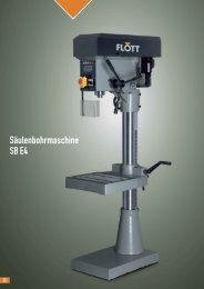
Betriebsanleitung KSM 150 - Flott
Betriebsanleitung KSM 150 - Flott
Betriebsanleitung KSM 150 - Flott

Sie wollen auch ein ePaper? Erhöhen Sie die Reichweite Ihrer Titel.
YUMPU macht aus Druck-PDFs automatisch weboptimierte ePaper, die Google liebt.
Konformitätserklärung<br />
D<br />
Hiermit erklären wir, dass die Bauart der auf der Frontseite beschriebenen Kantenschleifmaschine allen<br />
einschlägigen grundlegenden Sicherheits- und Gesundheitsanforderungen entspricht.<br />
EG-Richtlinien<br />
Angewendete harmonisierte Normen<br />
EG-Maschinenrichtlinie (2006/42/EG) DIN EN ISO 12100-1 und -2<br />
EG –EMV (89/336 EWG)<br />
EN 60204, Teil1<br />
Die Schutzziele der Niederspannungsrichtlinie<br />
werden eingehalten.<br />
E<br />
We declare that the belt sanding machine as described on the front page meets all general healthand<br />
safety rules.<br />
CEE-regulations<br />
Applicable harmonized standards<br />
CEE-machine standards (2006/42/EG) DIN EN ISO 12100-1 and -2<br />
CEE-EMV (89/336 EWG)<br />
EN 60204, part1<br />
The low voltage regulation is applied.<br />
Remscheid, den 10.05. 2010<br />
Dipl. Wirtsch. Ing. J.P. Arnz<br />
Entwicklungsleitung<br />
No.:<br />
Technische Unterlagen sowie Datendokumentation sind bei Arnz FLOTT GmbH Werkzeugmaschinen<br />
einzuholen. Der Ursprungstext für diese <strong>Betriebsanleitung</strong> wurde auf Deutsch geschrieben und in Englisch übersetzt.<br />
371771-08 Arnz FLOTT GmbH<br />
Werkzeugmaschinen<br />
Vieringhausen 131<br />
42857 Remscheid
2.0 Sicherheitshinweise – safety instructions<br />
Lesen Sie die Sicherheitshinweise und die <strong>Betriebsanleitung</strong> aufmerksam<br />
und vollständig durch!<br />
Read the safety instructions and operating instructions carefully and<br />
thoroughly!<br />
Augenschutz tragen!<br />
Keep eyes protected!<br />
Gehörschutz tragen!<br />
Keep ears protected!<br />
Geeignete Arbeitskleidung tragen!<br />
Wear suitable working clothes!<br />
Tragen sie bei langen Haaren ein Haarnetz!<br />
Wear protective hair covering to contain long hair!<br />
Werkstücke sicher spannen!<br />
Secure workpieces firmly!<br />
Vor umlaufenden Teilen schützen!<br />
Take care of rotating parts!<br />
Bei Wartungs- und Instandhaltungsarbeiten grundsätzlich den Netzstecker<br />
ziehen!<br />
In case of maintenance and service work disconnect from mains!<br />
Sicherheitshinweise D/E 2
3.0 Technische Daten/technical data<br />
Option<br />
TSE 280<br />
280 mm<br />
-1<br />
2800 min<br />
H<br />
L<br />
T<br />
<strong>KSM</strong> <strong>150</strong><br />
2250 x <strong>150</strong> mm<br />
V<br />
16 m / s<br />
109 mm<br />
850 mm<br />
400 V, 50 Hz, 1,1 kW<br />
°C<br />
°C<br />
10 - 40 °C<br />
Kg<br />
HxLxT<br />
No.<br />
75<br />
1000 mm x 1350 mm x 470 mm<br />
371650
4.0 Allgemeine Sicherheitsvorschriften<br />
è Die Maschine nie unbeaufsichtigt betreiben; verlassen Sie die Maschine erst, wenn sie zum Stillstand<br />
gekommen ist!<br />
è Nur für Originalersatzteile der Fa. "FLOTT" übernehmen wir die Gewährleistung eines störungsfreien<br />
Betriebs!<br />
D<br />
è Vor einem Schleifbandwechsel, bevor die Maschine geöffnet wird und vor jedem Umbau ist unbedingt der<br />
Netzstecker zu ziehen.<br />
è Vor dem Einschalten der Maschine ist sicherzustellen, daß alle Schutzvorrichtungen entsprechend<br />
positioniert si nd.<br />
è Die Maschine darf nur an die auf dem Typenschild angegebene Spannung angeschlossen werden.<br />
è Wenn die Maschine nicht beaufsichtigt wird, bitte den Netzstecker ziehen.<br />
è Bei der Benutzung der Maschine enganliegende Kleidung tragen, gegebenenfalls Ärmel aufkrempeln,<br />
Schmuck und Krawatten abnehmen und langes Haar zurückbinden oder bedecken.<br />
è Es ist darauf zu achten, daß für die zu schleifenden Werkstoffe das entsprechende Schleifband benutzt<br />
wird.<br />
è Rissige oder deformierte Schleifbänder dürfen nicht benutzt werden.<br />
è Stellen Sie die Bandschleifmaschine auf eine ebene Fläche und verschrauben Sie sie mit dieser.<br />
è Vor dem Aufspannen sind die Schleifbänder genau zu prüfen.<br />
è Das Tragen von Gehörschutzmitteln wird empfohlen.<br />
è Folgende Restrisiken sind zu beachten:<br />
- Gefährdung durch wegfliegende Werkzeugteile z.B. durch Werkzeugbruch,<br />
- Gefährdung durch wegfliegende Werkstücke,<br />
- Gefährdung durch elektrischen Strom,<br />
- Gefährdung durch Reststaubemission.<br />
è Schleifen und Polieren von Teilen aus Aluminium und seinen Legierungen<br />
Aufgewirbelter Aluminium - und Magnesiumstaub kann zu Explosionen führen, wenn Zündquellen, z.B.<br />
Funken, brennende Zigaretten, vorhanden sind.<br />
Es ist aber erforderlich, den Schleifstaub in gesonderte Absauganlagen abzuführen und Staubablagerungen<br />
in den Rohrleitungen zu verhindern.<br />
Wechselweises Schleifen von funkenreißenden und nicht funkenreißenden Werkstoffen ist nur auf dafür<br />
besonders ausgerüsteten Schleifmaschinen erlaubt. Diese Maschinen müssen über getrennte Schleifzonen<br />
und über getrennte Absauganlagen für die verschiedenartigen Stäube verfügen.<br />
Darüber hinaus sind besondere Wartungs - und Reinigungsintervalle zu beachten.<br />
Schleifmaschinen für wechselweises Schleifen müssen entsprechend gekennzeichnet sein.<br />
Die im einzelnen erforderlichen Schutzmaßnahmen beim Schleifen von Aluminium und seinen Legierungen<br />
sind bei den zuständigen Technischen Aufsichtsdiensten der jeweiligen Berufsgenossenschaften zu erfragen.<br />
Einzelheiten können auch den „Richtlinien zur Vermeidung von Gefahr von Staubbränden und<br />
Staubexplosionen beim Schleifen, Bürsten und Polieren von Aluminium und seinen Legierungen“ (ZH 1/32)<br />
entnommen werden.<br />
371771 D/E 4
D<br />
5.0 Arbeitsplätze der Maschine<br />
- Schleifen auf dem Schleiftisch<br />
Zum Schleifen auf dem Schleiftisch kann das Schleifaggregat sowohl in 90° - Position als auch in 0° - Position verwendet<br />
werden. Die Einstufung ist stufenlos, so daß jede beliebige Winkelposition des Schleifaggregats eingestellt werden kann.<br />
Werden längere Werkstücke an deren Längsseite geschliffen, öffnen Sie die an der Absaughaube der Antriebsrolle<br />
vorhandene Klappe. Nach Beendigung dieser Arbeiten ist die Klappe wieder in die Ausgangsposition zu bringen.<br />
- Schleifen an der Umlenkrolle<br />
Zum Schleifen an der Umlenkrolle ist der hierfür vorgesehene Schleiftisch mit Absauganschluß zu verwenden. Er kann in<br />
der Höhe so eingestellt werden, daß das Schleifband optimal ausgenutzt werden kann.<br />
- Schleifen mit dem Sonderzubehör Tellerschleifeinrichtung TSE 280<br />
Bei Schleifarbeiten an der Tellerschleifeinrichtung ist der hierzu vorgesehene Arbeitstisch zu verwenden. Er kann in der<br />
Höhe durch den Klemmhebel stufenlos zur Schleifscheibe eingestellt werden. Die Schutzhaube ist vor Arbeitsaufnahme<br />
nach hinten zu klappen und nach Beendigung wieder in die Ausgangslage zurückzuklappen.<br />
Bei allen Arbeiten ist die Absaugung wie in Kapitel 15.0 beschrieben anzuschließen.<br />
6.0 Transport, Handhabung, Lagerung und Lieferumfang<br />
Achtung! Lieferung unbedingt auf Vollständigkeit und Schäden überprüfen!<br />
Transportschäden sind umgehend dem Frachtführer (Spedition, Post, Bahn etc.) zu melden.<br />
(siehe gelbes Merkblatt)<br />
Die Maschine wird auf einer Palette geliefert. Jeglicher Transport hat auf dieser Palette mittels Hubwagen<br />
oder Gabelstapler zu erfolgen. Die verpackten Maschinen sind nicht stapelbar.<br />
- Maschine<br />
- Schleifband Korn 80<br />
- <strong>Betriebsanleitung</strong>.<br />
7.0 Aufstellen der Maschine<br />
Die Schleifmaschine ist auf einem festen Untergrund mit genügendem Sicherheitsabstand zu anderen Geräten und<br />
Einrichtungen aufzustellen und mit 4 Schrauben festzuschrauben.<br />
Folgende Funktionen sollten kontrolliert werden:<br />
- das Band läuft rund und leicht,<br />
- das Band berührt die Schleifanlage nicht.<br />
8.0 Installation<br />
Bitte überprüfen Sie, ob Stromart, Stromspannung und Absicherung mit den vorgeschriebenen Werten übereinstimmen.<br />
Ein Schutzleiteranschluß muß vorhanden sein. Netzabsicherung 10 A.<br />
Für den Anschluß der Maschine empfehlen wir das Anschlußkabel Nr.: 488761 (Typ HO7RN-F/5x1,5 • ; Länge
11.0 Bandwechsel<br />
(siehe Abbildung 1)<br />
a. Winkelanschlag (11), Blechschutz (8/13) und Anschlag (22) entfernen.<br />
b. Spannrolle mit Hebel (19) entspannen und den Hebel in den Sicherungshaken (20) einhängen.<br />
c. Altes Schleifband entfernen, neues Schleifband auflegen und mittig ausrichten.<br />
Achtung! Dabei unbedingt auf die Drehrichtung des Schleifbandes achten!<br />
d. Spannhebel lösen.<br />
12.0 Verstellung des Schleiftisches<br />
Zur optimalen Nutzung des Schleifbandes kann der Schleiftisch (10) in der Höhe verstellt werden. Hierzu die beiden<br />
Spannhebel (16) lösen und nach dem Verstellen des Schleiftisches wieder anziehen. (siehe Abbildung 1)<br />
13.0 Schleifen von Schweifungen<br />
Schleiftisch vertikal um 90° schwenken.<br />
Den rechten Schutz abnehmen und den mitgelieferten Tisch (1) in der benötigten Höhe in die Bohrung der Stütze<br />
einbringen und mit Spannhebel (2) klemmen. (siehe Abbildung 4)<br />
D<br />
14.0 Wartung<br />
Reinigen Sie die Umlenkrolle und die Schleifunterlage regelmäßig. Ein zufriedenstellendes Planschleifen kann nur mit<br />
einer einwandfreien Schleifunterlage erreicht werden. Anderenfalls muß diese ausgewechselt werden.<br />
15.0 Absaugung<br />
Bei jeglichem Betrieb der Bandschleifmaschine ist eine Absaugung anzuschließen, die sich gleichzeitig mit dem<br />
Einschalten der Maschine (z.B. über eine Induktionsspule) einschaltet.<br />
Der Anschluß der Absaugung hat mit flexiblen, schwer entflammbaren Absaugschlauch (Anschlußdurchmesser<br />
100 mm) an der Antriebsrolle zu erfolgen.<br />
Wir empfehlen unser staubgeprüftes Hochleistungs - Absauggerät HA <strong>150</strong>0 D.<br />
Ist eine geeignete, betriebliche Absaugung vorhanden, muß am Aufstellungsort eine Leistung von ca. 585 m³/h und eine<br />
Mindestluftgeschwindigkeit von 20 m/s vorhanden sein (notwendiger Unterdruck 1250 Pa).<br />
Bei Arbeiten auf dem Schleiftisch muß der Absaugstutzen an der Antriebsrolle angeschlossen sein.<br />
Bei Arbeiten am Schleifteller (TSE 280) ist der Absaugschlauch vom Anschluß der Antriebsrolle an den Anschluß des<br />
Schleiftisches anzubringen.<br />
Bei Arbeiten an der Umlenkrolle (Schleifen von Schweifungen) ist der Absaugschlauch vom Absaugstutzen der<br />
Antriebsrolle auf den Absaugstutzen des Arbeitstisches umzustecken.<br />
Das Umstecken der Absaugschläuche darf nur bei stillstehender Maschine erfolgen.<br />
16.0 Lärmemission<br />
Die nach EN 31202 mit CEN-TC 142 Ergänzung in Verbindung mit ISO 7960 ermittelte Lärmemission beträgt für den<br />
arbeitsplatzbezogenen Emissionswert L pA = 83,2 dB(A) Arbeitsgeräusch und 83,2 dB(A) im Leerlauf.<br />
Die Meßsicherheitskonstante K beträgt 4 dB(A).<br />
Der nach EN 23746 mit CEN-TC 142 Ergänzung ermittelte Schalleistungspegel beträgt L WA = 96,8 dB(A)<br />
Arbeitsgeräusch und 95,8 dB(A) im Leerlauf.<br />
Die Meßsicherheitskonstante K beträgt 4 dB(A).<br />
Folgende vom CEN-TC 142 festgelegte Ergänzungen, um eine Genauigkeitsklasse besser 3 dB zu erhalten, wurden<br />
berücksichtigt:<br />
- die Umgebungskorrekturfaktoren K 2A bzw. K 3A sind £ 4 dB, die Differenz zwischen Fremdgeräuschschalldruckpegel<br />
und Geräuschschalldruckpegel an jedem Meßpunkt ist 6dB<br />
- K 3A wird nach Anhang A, prEN 31204 berechnet<br />
- es wird eine quaderförmige Hüllfläche mit 9 Meßpunkten im Abstand von 1,0 m von der Bezugsfläche verwendet.<br />
Maschinenspezifische Einstellung:<br />
Schleifen von Spanplatte mit Schleifband P80 - Werkstückabmessungen 700x350x19 mm<br />
Mikrofonposition für den arbeitsplatzbezogenen Emissionswert: Höhe 1,5 m, Abstand von Maschinenkante 0,5 m.<br />
Die Werte, die hier angegeben sind, sind Emissionswerte und müssen damit nicht zugleich auch sichere<br />
Arbeitsplatzwerte darstellen. Da es keine Korrelation zwischen Emissionswerten und Arbeitsplatzwerten gibt, können<br />
diese nicht zuverlässig verwendet werden, um festzustellen, ob oder ob keine weiteren Vorkehrungen erforderlich sind.<br />
Faktoren, welche den derzeitigen Arbeitsplatzwert beeinflussen können, beinhalten die Dauer der Einwirkung, die<br />
Eigenart des Arbeitsraumes, andere Geräuschquellen, die Anzahl der Maschinen und anderen benachbarten Einflüsse.<br />
Die zuverlässigen Arbeitsplatz-werte können ebenso von Land zu Land variieren. Diese Information soll jedoch den<br />
Anwender befähigen, eine bessere Abschätzung von Gefährdung und Risiko zu machen.<br />
371771 D/E 6
D<br />
17.0 Lieferumfang TSE 280<br />
Bitte überprüfen Sie die Lieferung auf Vollständigkeit!<br />
1 Stk Schleifteller<br />
1 Stk Aufnahme Schleiftisch<br />
1 Stk Schleiftellerschutz mit Winkel<br />
1 Stk Tisch für TSE 280<br />
1 Stk Klemmhebel<br />
4 Stk Zylinderschraube M8x16 mm<br />
2 Stk Sechskantmutter M8<br />
6 Stk Scheibe A 8,4<br />
1 Stk Endscheibe<br />
1 Stk Senkschraube M6x25 mm<br />
1 Stk Klettbelag ø 280 mm<br />
1 Stk Schleiftellerbelag ø 280 mm, Korn 60<br />
2 Stk Senkschraube M8x25 mm<br />
2 Stk Scheibe A 8,4 (groß)<br />
18.0 Montage TSE 280<br />
a. Abdeckung am Motorlüfter entfernen;<br />
b. Zwei Sechskantmuttern M8 am Motorfuß lösen;<br />
(Bitte überprüfen, ob die beiden verbliebenen Schrauben festsitzen!).<br />
c. Schleiftellerschutz unter die beiden gelösten Sechskantmuttern schieben und leicht befestigen;<br />
d. Welle einfetten;<br />
e. Schleifteller auf die Motorwelle aufschieben und mit der Endscheibe sichern.<br />
Dabei Senkschraube M6x25 mm benutzen.<br />
f. Schleiftellerschutz nach dem Schleifteller ausrichten.<br />
Die Umlaufkante des Schleiftellerschutzes muß dabei ca. 2 mm hinter dem Schleiftellerbelag liegen. Die beiden<br />
Sechskantmuttern am Motorfuß fest anziehen.<br />
g. Die Aufnahme des Schleiftisches mit 4 Schrauben M8x16 und 4 Scheiben anschrauben.<br />
Tisch einsetzen und mittels Kreuzgriff sichern. Falls erforderlich muß der Schleiftisch durch Lösen der Zylinderschrauben<br />
parallel zum Schleifteller ausgerichtet werden. Der Tischabstand zur Schleiffläche darf aus Sicherheitsgründen 3 mm<br />
nicht überschreiten.<br />
h. Beim Schleifblattwechsel den Tisch abnehmen, oder in unterste Position und das Schleifblatt vom Schleifteller<br />
abziehen. Bei Montage eines neuen Schleifblattes den Klettbelag flächendeckend andrücken.<br />
Achtung! Das Schwenken des Schleiftisches gemäß und angebauter TSE 280 ist nur möglich, wenn sich der<br />
Schleiftisch in der untersten Position befindet.<br />
371771 D/E 7
4.0 General safety instructions<br />
è Do not leave the running machine, only in case of stand-still of machine.<br />
è Only for original ,,FLOTT“ spare parts we will take over the guarantee of a trouble-free factory.<br />
E<br />
è Before changing the grinding belt or opening the machine disconnect the machine from the mains power<br />
supply!<br />
è Before starting the machine connect all safety devices!<br />
è The machine should be connected to the mains power supply as indicated on the machine information<br />
plate.<br />
è Without supervision the machine should be unplugged.<br />
è The machine operator should wear tight - fitted clothes. Long sleeves should be rolled up, jewelry and<br />
neckties should be removed prior to operation. Long hair should be tight up or covered.<br />
è Use grinding belts according to the material to be grinded.<br />
è Cracked or deformed grinding belts should not be used.<br />
è The machine should be positioned and screwed on a level surface.<br />
è Before mounting the sanding belts have to be checked.<br />
è Use ear protections!<br />
è Following remaining risks exist:<br />
- danger of throwing tools e.g. by tool breakage<br />
- danger of throwing working pieces<br />
- danger of current<br />
- danger of residual dust emission<br />
è Grinding and polishing of aluminium parts and its alloys<br />
Raised aluminium and magnesium dust can cause explosions, if there is an ignition source, like sparks or a<br />
burning cigarette.<br />
Hence it is necessary to exhaust the grinding dust with a seperate extraction system and to prevent deposition<br />
of dust in the tubes.<br />
Alternating grinding of spark arcing and non spark arcing materials is only permitted on especially furnished<br />
grinding equipment. The grinding equipment must be provided with seperate grinding areas and extraction<br />
systems for the different dusts. In addition particular maintenance and purging intervals have to be observed.<br />
Grinding equipment for alternating grinding must be flagged accordingly.<br />
Information on particular protective measures necessary for the grinding of aluminium and its alloys can be<br />
given at the competent offices of Technical Control of the respective German employer´s lisbility insurance<br />
associations. Details can also be viewed in the „Richtlinien zur Vermeidung der Gefahr von Staubbränden<br />
und Staubexplosionen beim Schleifen, Bürsten und Polieren von Aluminium und seinen Legierungen“<br />
(guidelines for reporting the dangers of dust fires and dust explosions when grinding, brushing or polishing<br />
aluminium and its alloys) (ZH 1/32).<br />
371771 D/E 8
E<br />
5.0 Working places<br />
- Sanding on the sanding table<br />
For sanding on the sanding table (28) swing the sanding machine into the most comfortable position (infinitely variable 0°<br />
- 90°). It can be set stepless, so that every angular position of the guiding aggregate can be positioned.<br />
To sand long workpieces alongside open the dust exhaust hood at the motor pulley. After finishing this work the hood is<br />
to be put in the starting position.<br />
- Sanding at the guide pulley<br />
For sanding at the guide pulley use the sanding table.<br />
For comfortable working and proper use of the sanding belt adjust the sanding table in its height.<br />
- Sanding with the optional disk sanding assembly TSE 280<br />
For sanding at the TSE 280 open the protection hood, use the sanding table and adjust it in its height. Thighten the<br />
clamping lever properly.<br />
For safe sanding at the sanding belt the protection hood has to be closed. For all working processes the exhaust<br />
(as descibed at item 15.0) is to be used.<br />
6.0 Delivery, transport, handling and storage<br />
ATTENTION! Always check delivery for completeness and damage!<br />
The carrier (forwarder or railway) is to be informed immediately in case of transport damages.<br />
(s. yellow leaflet)<br />
The machine is packed on pallet, it has to be transported by lift or fork truck. The packed machines are no<br />
staple commodities!<br />
- sanding machine<br />
- one sanding belt coarse - grained<br />
- operation instructions.<br />
7.0 Setting up the machine<br />
The grinding machine should be placed on a level surface and screwed with four screws.<br />
Check that the belt moves freely and is not impeded in any way.<br />
8.0 Installation<br />
Please check whether type of current, current voltage and fusing agree with the prescribed values. There must be a<br />
protective earth terminal. Mains fusing 10 A.<br />
For conecting the machine we recommend the cable no.:488761. (type HO7RN-F/5x1,5; length
11.0 Changing the sanding belt<br />
(see figure 1)<br />
a. remove the angle stop (11), the sheet metal guard (8/13) and stop (22).<br />
b. release the driving pulley with the clamping lever (19) and secure it with the safety hook (20).<br />
c. remove the old sanding-belt and install a new one right in the middle of the two rollers.<br />
It is absolute necessary to prove the belt direction!<br />
d. release the clamping lever.<br />
12.0 Adjusting of sanding table<br />
For optimal using of belt the sanding table (10) can be adjust in the height; you have to loosen both clamping<br />
Levers (16) and tension again - after adjusting of sanding table. (see figure 1)<br />
13.0 Sanding of curves and bendings<br />
Turn the sanding-table into the 90° position.<br />
Remove the right guard (1) and install the supplied table into the bore of the support.<br />
Jam the table with star-handle (2). (see figure 4)<br />
E<br />
14.0 Maintenance<br />
Ensure that all moving parts are kept clean and that the belt is always in a good condition. Never use a badly worn or torn<br />
belt.<br />
15.0 Exhausting<br />
It is necessary to use a dust extractor for any work. The machine has to be connected with a flexible, uninflamable<br />
suction hose (∅ 100 mm) at the motor pulley.<br />
We highly recommend our high capacity dust extractor „FLOTT“ HA <strong>150</strong>0 D.<br />
If you use your own exhaust you need a suction rate of 585 m³/h, a minimum air velocity of 20 m/s and a minimum<br />
underpressure of 1250 Pa.<br />
For sanding on the sanding table connect the dust extractor at the two belt pulleys.<br />
For sanding with the TSE 280 disconnect the suction hose from the motor pulley and connect it to the suction inlet<br />
of the TSE working table. Disconnect the suction hoses only when machine stand still.<br />
For sanding at the guiding pulley disconnect the suction hose from the motor pulley and connect it to the suction inlet of<br />
the working table.<br />
16.0 Noise emission<br />
According to EN 31202, CEN-TC 142 and ISO 7960 the determined noise emission is:<br />
sound ranging L pA = 83,2 dB(A) and idle running 83,2 dB(A).<br />
The measuring constant K is 4 dB(A).<br />
According to EN 23746 and CEN-TC 142 the determined noise emission is:<br />
sound calculation L WA = 95,8 dB(A) and idle running 95,8 dB(A).<br />
The measuring constant K is 4 dB(A).<br />
Please consider following completion acc. To CEN-TC 142 in order to get a better precision classification than 3dB:<br />
- The correction factors of environment K 2A resp. K 3A are < 4 dB, the difference between seperate noise level and noise<br />
level at every measuring point is 6 dB.<br />
- K 3A will be calculated acc. to annex A, prEN 31204.<br />
- It will be used a square envelope surface with 9 measuring points with a distance of 1,0 m of the reference surface.<br />
Specified adjustment of machine:<br />
Grinding of composite board with sanding belt grain 80.<br />
Dim. of workpiece 700 x 350 x 19 mm<br />
Position of microphone for the emission value of working place: height 1,5 m, distance from edge of machine 0,5 m.<br />
The mentioned values are values of emission and must not be secure values of the working place. As there is no<br />
correlation between value of emission and value of working place, it is not possible to use these reliable in order to state<br />
whether further precautions are required or not.<br />
Factors which can influence the present value of working place, contain the duration of the influence, the peculiarity of<br />
working area, other noise sources, quantity of machines and other influences. The reliable values of the working place<br />
can also be different from country to country. This information shall help the user to evaluate the danger and risk.<br />
371771 D/E 10
E<br />
17.0 Scope of delivery TSE 280<br />
Please check completeness of delivery !<br />
1 sanding disc<br />
1 holder for sanding disc<br />
1 sanding-disc protection<br />
1 sanding table for TSE 280<br />
1 clamping lever<br />
4 hexagon head screws M8x16 mm<br />
2 hexagon head nuts M8<br />
6 washers A 8,4<br />
1 end washer<br />
1 countersunk screw M6x25 mm<br />
1 self adhesive tape ø 280 mm<br />
1 sanding disc cover ø 280 mm, K60<br />
2 countersunk screw M8x25 mm<br />
2 washer A 8,4<br />
18.0 Installation of TSE 280<br />
a. Remove the protection cap from the motorfan.<br />
b. Screw off two nuts M8 from the motor base.<br />
(Please check whether the remaining screws are fitted tigthly.<br />
c. Screw the sanding disc protection with these two screws tightly.<br />
d. Grease the shaft.<br />
e. Push the sanding disc onto the motorshaft and secure it with the end washer and a countersunk screw<br />
M6x25 mm.<br />
f. Adjust sanding disc protection acc. to sanding disc. Straighten the guard the way that it lies 2 mm behind the sanding<br />
disc cover. Tighten the two hexagon nuts M8 at the motor base.<br />
g. With 4 screws M8x16 mm and 8 washers screw on the support of the sanding-table. Insert the sanding table and<br />
secure it with the star handle.<br />
If necessary straighten the sanding table to the sanding-disc by loosen the hexagon head screws.<br />
For safety the distance between grinding table and sanding disc may not be more than 3 mm.<br />
h. For changing the sanding-disc cover please remove the sanding-table and draw off the old cover.<br />
Press the new sanding disc cover straight against the self adhesive tape of the sanding disc.<br />
Install the sanding table.<br />
Attention! Turning the sanding table into the 90° position with a fitted TSE 280 is only possible if the sanding<br />
table is in its lowest position.<br />
371771 D/E 11
Ersatzteilliste / List of spare parts<br />
Ausgenommen sind Teile, die aufgrund technischer Innovationen nicht mehr hergestellt werden.<br />
Except parts being no longer in production due no technical progress.<br />
Bestellnr. / order no.<br />
Abb.<br />
figure<br />
Pos.<br />
item<br />
Bezeichnung<br />
designation <strong>KSM</strong> <strong>150</strong><br />
1 1 Hauptschalter-Stecker-Kombination * 008659<br />
1 2 Motor 371647<br />
1 3 Abdeckung komplett 371635<br />
1 4 Antriebsrolle komplett * 371646<br />
1 5 Abdeckung 371636<br />
1 6 Lamellenstopfen 009753<br />
1 7 Zugfeder * 071638<br />
1 8 Schutz groß 372102<br />
1 9 Schleifmantel 371661<br />
1 10 Schleiftisch 071649<br />
1 11 Längsanschlag 071730<br />
1 12 Abtriebsrolle komplett * 371668<br />
1 13 Schutz klein 372109<br />
1 14 Grundkörper 371632<br />
1 15 Ständer 371626<br />
1 16 Spannhebel M8x25 009179<br />
1 17 Motorhalter 371662<br />
1 18 Zylindergriff 009199<br />
1 19 Hebel * 071673<br />
1 20 Federsicherung * 071674<br />
1 21 Sterngriffschraube M8x20 007249<br />
1 22 Anschlag * 071639<br />
1 23 Graphitauflage * 372079<br />
2 1 Druckfeder D-357-A * 009801<br />
2 2 Führungsbolzen 372071<br />
2 3 Rollenhalter 071701<br />
2 4 Exzentergriff komplett * 371666<br />
3 1 Achsbolzen * 071662<br />
3 2 Halter für Schleifmantel 071679<br />
4 1 Schleiftisch 071739<br />
4 2 Spannhebel 009099<br />
4 3 Aufnahme 071718<br />
4 4 Schleiftischhalter 071711<br />
4 5 Absaugung Schleiftisch 071746<br />
5 1 Schleiftischaufnahme 071783<br />
5 2 Schleiftischhalter 071770<br />
5 3 Schleiftisch mit Absaugstutzen 071781<br />
5 4 Schleifteller * 071763<br />
5 5 Schutz 071762<br />
5 6 Zentrierscheibe * 071764<br />
5 7 Schutzwinkel * 071761<br />
* Verschleißteile/consumable parts<br />
371771 D/E 12
7 8 9 10 11<br />
6<br />
5<br />
4<br />
16<br />
13<br />
12<br />
14<br />
15<br />
3<br />
17<br />
18<br />
19 20<br />
2<br />
1<br />
21<br />
22<br />
21<br />
21<br />
23<br />
Abb./fig.1<br />
371771 D/E 13
1<br />
2<br />
1<br />
Abb./fig.2<br />
3<br />
4<br />
2<br />
Abb./fig.3<br />
1<br />
5<br />
4<br />
3<br />
2<br />
Abb./fig.4<br />
371771 D/E 14
1<br />
2<br />
3<br />
4<br />
5<br />
6<br />
7<br />
Abb./fig.5<br />
371771 D/E 15
371771 D/E 16