Funkempfänger für DiMAX Navigator FM EU/US RC ... - AllAboutLGB
Funkempfänger für DiMAX Navigator FM EU/US RC ... - AllAboutLGB
Funkempfänger für DiMAX Navigator FM EU/US RC ... - AllAboutLGB

Sie wollen auch ein ePaper? Erhöhen Sie die Reichweite Ihrer Titel.
YUMPU macht aus Druck-PDFs automatisch weboptimierte ePaper, die Google liebt.
<strong>Funkempfänger</strong> <strong>für</strong> <strong>DiMAX</strong> <strong>Navigator</strong> <strong>FM</strong> <strong>EU</strong>/<strong>US</strong><br />
<strong>RC</strong> Receiver for <strong>DiMAX</strong> <strong>Navigator</strong> <strong>FM</strong> <strong>EU</strong>/<strong>US</strong><br />
Art.-Nr. / Item No.: 8133001/8132001<br />
Version 1.2
1. Einleitende Information<br />
Die <strong>DiMAX</strong> Funktechnik baut auf einer<br />
bidirektionalen <strong>FM</strong>-Funklösung auf.<br />
Das garantiert beste Funkleistung. Der<br />
<strong>Funkempfänger</strong> kann mit bis zu acht<br />
Funksendern betrieben werden.<br />
Die Reichweite ist stark von örtlichen<br />
Gegebenheiten abhängig. Andere<br />
Sender auf gleicher Frequenz wie z.B.<br />
Garagentüröffner, Funkthermometer,<br />
Funkkopfhörer, Funkmäuse oder Funktastaturen,<br />
sowie Hindernisse zwischen<br />
Sender und Empfänger oder Wände<br />
können die Funkreichweite teilweise<br />
stark einschränken.<br />
1.1 Lieferumfang<br />
• <strong>DiMAX</strong> <strong>Funkempfänger</strong><br />
• Antenne<br />
• Verbindungskabel<br />
• Bedienungsanleitung<br />
2. Anschluss<br />
Bitte stecken Sie vor Inbetriebnahme<br />
des <strong>Funkempfänger</strong>s die beiliegende<br />
Antenne in die da<strong>für</strong> vorgesehene kleine<br />
Öffnung auf der rechten Gehäuseoberseite.<br />
Verwenden Sie zum Anschluss<br />
des Empfängers das beiliegende Kabel<br />
mit zwei Westernsteckern. Verbinden<br />
Sie eine der zwei Buchsen des <strong>Funkempfänger</strong>s<br />
mit einer Buchse an der<br />
Zentrale. Beide Buchsen sind identisch.<br />
Die zweite Buchse kann zum Anschluss<br />
<strong>für</strong> ein weiteres Busgerät genutzt<br />
werden.<br />
1. General Information<br />
The <strong>DiMAX</strong> <strong>RC</strong> system is based on<br />
state-of-the-art bidirectional <strong>FM</strong> technology.<br />
This guarantees the best radio control<br />
range. The <strong>RC</strong> Receiver can be used<br />
with up to 4 <strong>RC</strong> transmitters. The radio<br />
range depends on local conditions.<br />
Transmitters on the same frequency like<br />
garage door openers, radio thermometers,<br />
radio headphones, radio mouse or<br />
radio keyboards and obstacles between<br />
transmitter and receiver like walls may<br />
limit the radio range.<br />
1.1 Scope of Supply<br />
• Multi-<strong>RC</strong> Receiver<br />
• Antenna<br />
• 1 x Bus Cable<br />
• Manual<br />
2. Hook-Up<br />
Install the antenna into the intended<br />
small device on the right upper side<br />
of the case before starting up the<br />
<strong>DiMAX</strong> <strong>RC</strong> Receiver. To connect the <strong>RC</strong><br />
Receiver to the Central Station use the<br />
supplied 20ft cable with phone-style<br />
connectors. Use one of the two sockets<br />
to connect the receiver to the central<br />
station. Both sockets are identical. The<br />
second socket can be used to connect<br />
other bus components. The cable length<br />
should exceed 20ft.<br />
2
2.1. Standort und Reichweite<br />
Stellen Sie den Multi-<strong>Funkempfänger</strong><br />
so auf, dass die Reichweite von keinem<br />
Punkt Ihrer Anlage aus überschritten<br />
wird. Der Empfänger sollte mindestens<br />
1 Meter Abstand zu Trafos, Digitalzentrale<br />
und Gleisen haben. Die Reichweite<br />
des <strong>Funkempfänger</strong>s beträgt ca. 50<br />
Meter. Im Freilandbetrieb auch deutlich<br />
mehr. Verlegen Sie das Buskabel nicht<br />
parallel zu den Gleisen. Probieren Sie<br />
ggf. mehrere Positionen aus um den<br />
optimalen Standort zu ermitteln. Die<br />
Antenne muss senkrecht sein! Das<br />
Anbringen einer Metallfläche (ca. 20 x<br />
20cm) unter dem Empfängergehäuse<br />
kann die Reichweite des Systems<br />
verbessern.<br />
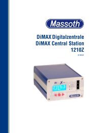
2.1. Positioning and Range<br />
Position the receiver so that the range<br />
is not exceeded by any portion of your<br />
layout. The receiver should have at least<br />
a 3 feet distance from transformers, the<br />
digital central station and the tracks. A<br />
radio range of approximately 150 feet<br />
can be reached and even more. Do not<br />
lay the cable parallel to the tracks. If<br />
necessary try several positions to determine<br />
the best location for the receiver.<br />
Keep the antenna in vertical position.<br />
An additional metal surface (approx. 20<br />
x 20m) under the receiver can enhance<br />
the radio range.<br />
Abbildung 1: Aufstellung und Reichweite<br />
Illustration #1: Positioning and range<br />
3
2.2. Statusled (Aktivität)<br />
Der Betriebszustand des <strong>Funkempfänger</strong>s<br />
wird durch die STAT<strong>US</strong> LED (mit<br />
ACT. auf dem Gehäuse gekennzeichnet)<br />
angezeigt. Nach dem Einschalten kann<br />
es bis zu 15 Sek. dauern bis der Empfänger<br />
betriebsbereit ist!<br />
2.2. Status LED (Activity)<br />
The Operation Mode of the <strong>RC</strong> Receiver<br />
is shown by the STAT<strong>US</strong> LED, named<br />
„ACT“. It may take the receiver up to 15<br />
sec. after the power-up to be ready for<br />
operation!<br />
Betriebszustand der STAT<strong>US</strong> LED<br />
An<br />
(dauerhaft)<br />
Blinken sym.<br />
Blinken asym.<br />
Regulärer Betrieb<br />
mit einem oder mehreren<br />
Funksendern<br />
Funkstörung vorhanden<br />
<strong>Funkempfänger</strong><br />
Standby<br />
Nach dem Einschalten<br />
oder wenn längere<br />
Zeit kein Sender aktiv<br />
ist.<br />
2.3. Funk-Konfiguration<br />
Die Einstellungen am Multi-<strong>Funkempfänger</strong><br />
werden mit dem integrierten<br />
4-fach Dipschalter vorgenommen: Es<br />
stehen insgesamt vier Funkkanäle zur<br />
Verfügung. Diese können bei Störungen<br />
und Empfangsproblemen gewechselt<br />
werden um die Stabilität und die Reichweite<br />
zu verbessern. Achten Sie darauf,<br />
dass der Kanalwechsel auch an den entsprechenden<br />
Funksendern durchgeführt<br />
werden muss. Die Einstellungen hierzu<br />
finden Sie im Menü Ihres <strong>DiMAX</strong> Navi-<br />
Operation Mode of the STAT<strong>US</strong> LED<br />
On (steady) regular operation<br />
with one or several<br />
<strong>RC</strong> transmitters<br />
Flashing<br />
symmetric<br />
Flashing<br />
asymmetric<br />
radio interferences<br />
detected<br />
<strong>RC</strong> receiver standby<br />
after switch-on or if<br />
no <strong>RC</strong> transmitter is<br />
detected within a few<br />
seconds.<br />
2.3. <strong>RC</strong> Configuration<br />
The <strong>RC</strong> configuration is set with the<br />
integrated DIP-switches. Four radio frequencies<br />
are available. If interferences<br />
occur, the frequency may be changed<br />
to solve this problem and to ensure<br />
high quality radio control. A frequency<br />
change will also be required for the <strong>RC</strong><br />
transmitters. The transmitter settings<br />
are to be found in the <strong>Navigator</strong>‘s menu,<br />
provided a transmitter is installed. The<br />
“First Registration Rights“ define if an<br />
unknown <strong>RC</strong> transmitter, which has not<br />
4
gators. Die Anmelderechte legen fest, ob<br />
sich weitere Funkteilnehmer anmelden<br />
dürfen. Bereits zuvor angemeldete<br />
Funkteilnehmer können sich auch nach<br />
Sperrung der Neuanmeldung anmelden<br />
und alle Funktionen nutzen. Für Teilnehmer,<br />
die noch nicht angemeldet waren,<br />
ist die Anmeldung jedoch gesperrt und<br />
kann nicht durchgeführt werden. Damit<br />
verhindern Sie unerwünschten Zugriff<br />
auf Ihre Anlage.<br />
Um die Einstellungen vorzunehmen,<br />
öffnen Sie bitte das Gehäuse des<br />
Empfängers. Schrauben Sie hierzu<br />
die vier Schrauben auf der Unterseite<br />
des Gehäuses auf, anschließend kann<br />
der Deckel des Gehäuses abgehoben<br />
werden. Achten Sie darauf, dass die<br />
Elektronik nicht herausfällt, verschmutzt<br />
oder beschädigt wird.<br />
Starten Sie nach dem Wechsel des<br />
Funkkanals den <strong>Funkempfänger</strong> neu<br />
um die Änderungen zu übernehmen.<br />
Es genügt das Abklemmen und<br />
erneute Anklemmen des Buskabels<br />
am Empfänger. Auch der Funksender<br />
im <strong>Navigator</strong> muss auf den gewählten<br />
Funkkanal eingestellt und anschließend<br />
neu gestartet werden.<br />
yet been used with this <strong>RC</strong> receiver is<br />
allowed to register with this <strong>RC</strong> receiver.<br />
Registered <strong>RC</strong> transmitters will always<br />
negotiate the connection to <strong>RC</strong> receiver,<br />
even if the “First Registration Right“ has<br />
been set to “Off“. Devices that are unknown<br />
to this <strong>RC</strong> Receiver are not able<br />
to access the receiver which means,<br />
that they cannot connect to the system.<br />
This will prevent unwanted access to the<br />
control of your layout. To perform any<br />
configuration changes, open the housing<br />
of the <strong>RC</strong> receiver. Unscrew the four<br />
screws on the bottom of the housing<br />
and remove the cover. Do not to drop<br />
the circuit board or harm or modify it.<br />
Keep dust and dirt out of the housing<br />
and away from the circuitry. Do not try<br />
to clean the circuitry.<br />
After changing the settings restart the<br />
receiver by removing the cable and<br />
reconnecting it. The transmitter, which<br />
is installed in the <strong>Navigator</strong> needs to<br />
be set to the new settings too. Please<br />
reconfigure the <strong>Navigator</strong> in the <strong>RC</strong><br />
configuration menu.<br />
5
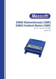
Abbildung 2: DIP-Schalter zur Einstellung des Funkkanals<br />
Illustration #2: DIP-Switch to select <strong>RC</strong>-channel<br />
Kanal<br />
Channel<br />
DIP 1 DIP 2<br />
Frequenz <strong>EU</strong><br />
<strong>RC</strong> Frequencies <strong>EU</strong><br />
Frequenz <strong>US</strong><br />
<strong>RC</strong> Frequencies <strong>US</strong><br />
1 OFF OFF 433,1 MHz 915 MHz<br />
2 ON OFF 433,6 MHz 916 MHz<br />
3 OFF ON 434,2 MHz 917 MHz<br />
4 ON ON 434,7 MHz 918 MHz<br />
DIP<br />
Anmelderechte <strong>für</strong> unbekannte Funkteilnehmer<br />
First registration rights for unknown PC participants<br />
Neuanmeldung gestattet<br />
new registration allowed<br />
Neuanmeldung nicht gestattet<br />
new registration not allowed<br />
DIP 4 ON OFF<br />
= Werkseinstellung / factory settings DIP3=keine Funktion / no function<br />
6
2.4. ID - Identifikationsnummer<br />
Der <strong>Funkempfänger</strong> verfügt selbst über<br />
keine eigene ID. Er ist passiv. Mit der<br />
Anmeldung eines Funksenders wird der<br />
Teilnehmer von der Zentrale erkannt und<br />
eine ID wird automatisch zugewiesen.<br />
Daten <strong>für</strong> diese ID leitet der Funksender<br />
automatisch an den entsprechenden<br />
Empfänger weiter.<br />
3. Firmware-Update<br />
Der <strong>DiMAX</strong> <strong>Funkempfänger</strong> kann jederzeit<br />
mit der neuesten Firmware ausgestattet<br />
werden. Dies geschieht über die<br />
Massoth-Buchse mittels des Massoth<br />
PC-Moduls 100A oder einer <strong>DiMAX</strong><br />
Zentrale. Sollten Sie keine Möglichkeit<br />
haben, das Gerät selbst upzudaten, so<br />
ist Ihnen Ihr Händler gerne behilflich.<br />
Natürlich kann das Update bei Bedarf<br />
gegen Unkostenerstattung auch beim<br />
Hersteller durchgeführt werden.<br />
Für das Firmwareupdate muss der<br />
<strong>Funkempfänger</strong> mit der Massoth-Bus<br />
Buchse am PC-Modul oder der Zentrale<br />
angeschlossen sein.<br />
Es dürfen keine weiteren Anschlüsse<br />
verbunden sein.<br />
Starten Sie am PC die <strong>DiMAX</strong>-Updatesoftware<br />
und laden Sie die aktuelle<br />
Software <strong>für</strong> den Empfänger. Es folgt die<br />
Eingabe des seriellen Schnittstelle am<br />
PC (COM-Port). Während dem Update<br />
blinkt die rote LED des <strong>Funkempfänger</strong>s<br />
gleichmäßig. Der <strong>Funkempfänger</strong> ist nun<br />
2.4. ID – identification number<br />
The <strong>RC</strong> Receiver does not require an<br />
ID. It is completely passive. When a <strong>RC</strong><br />
Sender is connected to the <strong>RC</strong> Receiver,<br />
the central station will set an ID for<br />
the Sender. Data for this <strong>RC</strong> Sender is<br />
forwarded by the <strong>RC</strong> Receiver automatically.<br />
3. Firmware update<br />
The <strong>DiMAX</strong> Receiver may be updated at<br />
any time using the Massoth PC module<br />
100A or a <strong>DiMAX</strong> Central station.<br />
Connect the PC module to the Massoth<br />
terminal and update the firmware.<br />
No other component should be connected<br />
to the receiver during updating.<br />
In case you cannot update the receiver,<br />
your dealer will gladly help. In addition<br />
Massoth Electronics may do an upgrade<br />
for a low service charge.<br />
Start the <strong>DiMAX</strong> PC Update software<br />
and open the current update file for the<br />
receiver. Select the COM-port in use.<br />
During the update the red LED will flash.<br />
After the update the receiver is ready<br />
for operation with the new software<br />
version.<br />
In case of a malfunction during updating,<br />
the PC will display a warning and<br />
the updating process will be terminated.<br />
The receiver will be in the update mode<br />
if switched on again. This is shown by<br />
the fast blinking red LED.<br />
7
mit der neusten Software ausgestattet<br />
und betriebsbereit.<br />
Tritt während dem Update ein Fehler<br />
auf, wird dies am Bildschirm angezeigt,<br />
die Updateprozedur wird abgebrochen.<br />
Der <strong>Funkempfänger</strong> erwartet beim nächsten<br />
Neustart automatisch die Installation<br />
der neuesten Software, erkennbar<br />
durch das 5-fach schnelle Blinken der<br />
LED beim Starten des <strong>Funkempfänger</strong>s.<br />
8
4. Technische Daten<br />
Spannung: 12-24 V DC (je nach<br />
Zentrale)<br />
Stromaufnahme: 30 mA im<br />
Ruhezustand<br />
Frequenzband: 433,0 – 434,7 MHz<br />
Sendeleistung: max. 9,5 mW<br />
Temperaturbereich: -20 - +45°C<br />
Abmessungen: 68 x 78 x 20 mm<br />
(L x B x H)<br />
Hinweis zur Temperatur: Um Kondenswasserbildung<br />
zu vermeiden, benutzen<br />
Sie die Elektronik bei Temperaturen<br />
unter 0°C nur, wenn diese vorher aus<br />
einem beheizten Raum kommt. Die<br />
Wärme die während des Fahrbetriebs<br />
erzeugt wird, reicht aus um Kondenswasserbildung<br />
zu verhindern.<br />
4. Technical specifications<br />
Power Supply: 12 to 24 Volts DC<br />
(depend on central station)<br />
Current: 30 mA in idle<br />
Frequency range:<br />
433,0 – 434,7 MHz (<strong>EU</strong>)<br />
915,0 – 918,0 MHz (<strong>US</strong>)<br />
Transmitting output: max. 9,5 mW<br />
Temperature range: -4°F to +113°F<br />
Measurements: 68 x 78 x 20 mm<br />
(L x W x H)<br />
Note regarding the operating temperature:<br />
to prevent the production of<br />
condensed water, use the Multi-<strong>RC</strong><br />
Module in freezing conditions only if<br />
it was previously stored in a heated<br />
environment. The heat produced during<br />
operation is sufficient to prevent<br />
condensed water.<br />
9
4.1 Garantie, Reparatur,<br />
Kundendienst<br />
MASSOTH gewährt die Fehlerfreiheit<br />
dieses Produkts <strong>für</strong> ein Jahr. Die gesetzlichen<br />
Regelungen können in einzelnen<br />
Ländern abweichen. Verschleißteile sind<br />
von der Garantieleistung ausgeschlossen.<br />
Berechtigte Beanstandungen<br />
werden kostenlos behoben. Für Reparatur-<br />
oder Serviceleistungen übergeben<br />
Sie das Produkt bitte Ihrem Fachhändler<br />
oder senden es direkt an den Hersteller.<br />
Unfrei zurückgesendete Sendungen<br />
werden nicht angenommen. Eine Kopie<br />
des Kaufbelegs wird vorausgesetzt.<br />
Für Schäden durch unsachgemäße<br />
Behandlung oder Fremdeingriff oder<br />
Veränderung des Produkts besteht kein<br />
Garantieanspruch. Der Anspruch auf<br />
Serviceleistungen erlischt unwiderruflich.<br />
Irrtümer und Änderungen vorbehalten.<br />
Auf unserer Internetseite finden<br />
Sie die jeweils aktuellen Broschüren,<br />
Produktinformationen, Dokumentation<br />
und Softwareprodukte rund um<br />
MASSOTH-Produkte.<br />
4.1 Warranty, Service,<br />
Support<br />
MASSOTH warrants this product against<br />
defects in materials and workmanship<br />
for one year from the original date of<br />
purchase. Other countries might have<br />
different legal warranty situations.<br />
Normal wear and tear, consumer<br />
modifications as well as improper<br />
use or installation are not covered.<br />
Peripheral component damage is not<br />
covered by this warranty. Valid warranty<br />
claims will be serviced without charge<br />
within the warranty period. For warranty<br />
service please return the product to<br />
you dealer or send it directly to the<br />
manufacturer. Return shipping charges<br />
are not covered by MASSOTH. Please<br />
include your proof of purchase with the<br />
returned goods. Errors and changes<br />
excepted.<br />
Please check our website for up to date<br />
brochures, product information,<br />
documentation and software updates.<br />
10
4.2 Hotline<br />
Serviceanfragen richten Sie bitte an:<br />
Massoth Elektronik GmbH<br />
Mo 14:00-17:30 sowie Do 8:00-12:00<br />
FON +49 (0)6151-35077-38<br />
FAX +49 (0)6151-35077-44<br />
hotline@massoth.de<br />
4.2 Hotline<br />
For technical support contact:<br />
Massoth Elektronik GmbH, Germany<br />
Mo 2:00-5:30 p.m.<br />
Thu 8:00-12:00 a.m.<br />
FON +49 (0)6151-35077-38<br />
FAX +49 (0)6151-35077-44<br />
hotline@massoth.de<br />
Massoth Electronics <strong>US</strong>A<br />
6585 Remington Dr. Suite 200<br />
Cumming, GA 30040<br />
9:00 a.m. to 4:00 p.m. EST Mo thru Fr<br />
Ph. +1 770-886-6670<br />
Fax +1 770-889-6837<br />
hotline@massoth.com<br />
RoHS<br />
032376o<br />
Dieses Produkt entspricht den CE Konformitätsrichtlinien <strong>für</strong> elektrische Kleingeräte<br />
in der aktuellen Fassung.<br />
This unit conforms to the CE Standards<br />
Dieses Produkt ist nach den aktuellen EG Richtlinien umgangssprachlich „bleifrei“<br />
hergestellt und damit RoHS-konform.<br />
This unit is manufactured according to the latest EG Standards for lead free<br />
manufacturing conforming to RoHS Standard.<br />
Entsorgen Sie das Produkt nicht im Hausmüll. Nutzen Sie bitte den da<strong>für</strong><br />
vorgesehenen Elektroschrott.<br />
Please dispose of according to your State regulations.<br />
Werfen Sie das Produkt nicht in offenes Feuer oder durch Hitze entflammbare<br />
Brennstoffe.<br />
Do not dispose of in open fire.<br />
11
MADE<br />
IN<br />
GERMANY<br />
Massoth Elektronik GmbH<br />
Frankensteiner Str. 28 · D-64342 Seeheim · Germany<br />
FON: +49 (0)6151-35077-0 · FAX: +49 (0)6151-35077-44<br />
eMail: info@massoth.de · www.massoth.de<br />
813x001_0510_ML