Einbau - Massoth
Einbau - Massoth
Einbau - Massoth

Create successful ePaper yourself
Turn your PDF publications into a flip-book with our unique Google optimized e-Paper software.
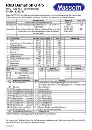
eMOTION XL Anschlussanleitung<br />
eMOTION XL Installation Manual<br />
Art.-Nr. / Item No.: 8150001<br />
Version 2.3
Einleitende Information<br />
Sehr geehrte Kunden, wir empfehlen<br />
beide Anleitungen und vor allem auch<br />
die Warnhinweise vor der Inbetriebnahme<br />
gründlich zu lesen und diese zu<br />
Beachten. In diesem Handbuch soll der<br />
Anschluss des eMOTION XL Lokdekoders<br />
erläutert werden.<br />
Introduction<br />
Dear customer, we highly recommend<br />
to read both product manuals and<br />
especially the warning notes thoroughly<br />
before operation. This manual describes<br />
the installation of the eMOTION XL<br />
decoder.<br />
HINWEIS: Funktionsausgänge<br />
Die Spannung der Licht- und Funktionsausgänge<br />
ist im Auslieferungszustand<br />
auf volle Gleisspannung<br />
eingestellt! Vergewissern Sie sich<br />
VOR dem Anschluss der Lampen und<br />
Funktionsausgänge das die Spannung<br />
entsprechend der CV-Liste richtig eingestellt<br />
ist! Für Schäden durch Nichtbeachtung<br />
dieses Hinweises übernehmen<br />
wir keine Haftung.<br />
Note concerning the function outputs:<br />
The function outputs are set per<br />
default to full track voltage! Make sure<br />
the CVs of the function outputs are set<br />
to the appropriate value before hooking<br />
up any lights or other accessories.<br />
<strong>Massoth</strong> cannot be responsible for<br />
any damage if this is disregarded.<br />
2
Inhaltsverzeichnis<br />
Grundlegende Information...............<br />
Funktionsumfang.............................<br />
Lieferumfang....................................<br />
Inbetriebnahme................................<br />
Motor- und Gleisanschluss..............<br />
<strong>Einbau</strong>..............................................<br />
Erweiterte Einstellungen...................<br />
Anschlüsse auf der Oberseite..........<br />
Licht- und Funktionsausgänge.........<br />
<strong>Einbau</strong> in Loks ohne Schnittstelle....<br />
<strong>Einbau</strong> in Loks m. LGB ®<br />
Schnittstelle.....................................<br />
<strong>Einbau</strong> in Loks m. LGB ® DCC<br />
Schnittstelle.....................................<br />
<strong>Einbau</strong> in Loks m. Aristocraft<br />
Schnittstelle.....................................<br />
Anschluss SUSI/<strong>Massoth</strong> Bus.........<br />
Technische Daten............................<br />
Garantie, Reparatur, Kundendienst..<br />
Hotline..............................................<br />
Table of Contents<br />
General Information.........................<br />
Summary of Functions.....................<br />
Scope of Supply...............................<br />
Hook-Up..........................................<br />
Motor and track connection.............<br />
Installation.......................................<br />
Advanced settings............................<br />
Terminals on the upper side............<br />
Light- and function outputs.............<br />
Installation without interface............<br />
Installation with LGB ® decoder<br />
interface...........................................<br />
Installation with LGB ® DCC<br />
interface...........................................<br />
Installation with a Aristocraft DCC<br />
interface...........................................<br />
Using the SUSI/<strong>Massoth</strong> bus...........<br />
Technical Data.................................<br />
Warranty, Service, Support..............<br />
Hotline..............................................<br />
4<br />
4<br />
5<br />
6<br />
6<br />
7<br />
7<br />
7<br />
9<br />
10<br />
10<br />
11<br />
12<br />
13<br />
13<br />
14<br />
15<br />
3
1. Grundlegende Informationen<br />
Wir empfehlen beide Anleitungen<br />
gründlich zu lesen, bevor Sie den neuen<br />
Dekoder in Betrieb nehmen.<br />
Einige Funktionen sind nur mit der<br />
aktuellsten Firmware nutzbar, führen Sie<br />
bei Bedarf ein Update durch.<br />
1.1. Funktionsumfang<br />
• 14,28 und 128 Fahrstufen<br />
• 256 interne Fahrstufen<br />
• 10239 Lokadressen<br />
• programmierbare Fahrkurve<br />
• Anfahr-, Mittel- und Höchstgeschwindigkeit<br />
(sowie Verzögerungszeiten)<br />
einstellbar<br />
• Serielle und parallele Steuerung für<br />
alle Licht- und Funktionsausgänge<br />
incl. LGB ® P-Soundupdates<br />
• Digital- und Analogbetrieb mit automatischer<br />
Erkennung<br />
• Kompatibel zu NMRA DCC und LGB ®<br />
MZS (alle Generationen)<br />
• Lastregelung neuester Generation<br />
(für Digital- und Analogbetrieb)<br />
• Einstellbare Motorfrequenz<br />
(70Hz - 16kHz)<br />
• 3 Lichtanschlüsse (vorne, hinten,<br />
innen) max. je 0,3 A<br />
• 6 Funktionsausgänge (alle mit konfigurierbaren<br />
Sonderfunktionen) max.<br />
je 0,6A<br />
• Licht- und Funktionsausgänge dimmbar<br />
und analog aktivierbar<br />
1. General Information<br />
We recommend to read this manual<br />
carefully before the decoder is installed<br />
and operated.<br />
Some functions require the latest firmware<br />
for availability. Please update the<br />
decoder with the latest firmware.<br />
1.1. Summary of Functions<br />
• 14,28 and 128 speed steps<br />
• 256 internal speed steps<br />
• 10239 addresses<br />
• Programmable driving characteristics<br />
• Adjustable starting speed, medium<br />
speed and maximum speed (with<br />
acceleration/deceleration time)<br />
• Serial and parallel control of all<br />
light and function outputs, incl. LGB ®<br />
P-Sound updates<br />
• Digital and analog operation with<br />
automatic recognition<br />
• Compatible with NMRA DCC and<br />
LGB ® MTS (all generations)<br />
• Latest technology of load control<br />
(digital and analog)<br />
• Adjustable motor frequency<br />
(70Hz - 16kHz)<br />
• 3 light outputs (front, rear, interior)<br />
max. 0,3 Amps each<br />
• 6 function outputs (each programmable<br />
with special functions) max 0,6<br />
Amps each<br />
4
• Programmierbare Blinklicht-,<br />
Impuls- und Taktgeberfunktion<br />
• 2 zusätzliche Kontakteingänge<br />
• Rangiergang (mit freier Funktionszuordnung)<br />
• einfache Funktionszuordnung für alle<br />
Funktionsausgänge<br />
• alle Funktionsausgänge frei adressierbar<br />
(F1 - F16)<br />
• Gesamtbelastbarkeit 4 Ampere<br />
(Motorendstufe und Funktionsausgänge)<br />
• Motorendstufe mit 3,5 Ampere belastbar<br />
(für bis zu 2 Motoren)<br />
• Spannungspufferanschluss für unterbrechungsfreien<br />
Lauf integriert<br />
• Überlast- und Temperaturschutz für<br />
Motor- und Funktionsausgänge<br />
• Resetfunktion für alle CV-Werte<br />
• Firmware updatefähig<br />
• Light and function outputs may be<br />
dimmed and activated in analog<br />
mode<br />
• Programmable blinking light, shorttime<br />
function, and pulse generator<br />
function<br />
• 2 additional contact inputs<br />
• Switching speed (with free function<br />
mapping)<br />
• Easy to use function mapping<br />
• Free command allocation of all<br />
function outputs (F1 - F16)<br />
• Maximum total load 4 Amps (motor<br />
and function output)<br />
• 3 Amps motor power amplifier<br />
(usable for 2 motors)<br />
• Connector for power buffer (accessory)<br />
for smooth running integrated<br />
• Overload and temperature protection<br />
for motor and function outputs<br />
• Reset function for all CV values<br />
• Firmware easy to be updated<br />
1.2 Lieferumfang<br />
• eMOTION XL Dekoder<br />
• LGB ® DCC-Schnittstellenkabel<br />
• 2 LGB ® -Getriebeanschlusskabel<br />
(je 4 Stck.)<br />
• 2 Schrauben 2,9 x 13 mm<br />
• 2 Schrauben 2,9 x 19 mm<br />
• Anschlussanleitung<br />
• Konfigurationsanleitung<br />
1.2 Scope of Supply<br />
• eMOTION XL Decoder<br />
• LGB ® DCC-interface cable<br />
• 2 LGB ® -motorblock connecting cables<br />
(4 pcs. each)<br />
• 2 Screws 2,9 x 13 mm<br />
• 2 Screws 2,9 x 19 mm<br />
• Connection manual<br />
• Configuration manual<br />
5
2. Inbetriebnahme<br />
Bauen Sie den Dekoder sorgfältig<br />
nach den Anschlussplänen in dieser<br />
Bedienungsanleitung in die Lok ein. Der<br />
Dekoder ist generell gegen Kurzschlüsse<br />
oder Überlastung gesichert. Werden<br />
jedoch beim <strong>Einbau</strong> Kabel vertauscht<br />
oder Kabel verschiedener Funktionen<br />
(z.B. Gleis + Motor) kurzgeschlossen,<br />
kann diese Sicherung nicht wirken und<br />
der Dekoder wird zerstört.<br />
2.1 Motor- und Gleisanschluss<br />
Verbinden Sie das weiße (Gleis +) und<br />
braune (Gleis -) Kabel mit dem Gleisanschluss<br />
des Getriebes.<br />
Verbinden Sie das gelbe (Motor +) und<br />
grüne (Motor -) Kabel mit dem Motor<br />
im Getriebe.<br />
Für den <strong>Einbau</strong> in Loks mit 2 Motoren<br />
sind 2 Sätze der Getriebeanschlusskabel<br />
im Lieferumfang enthalten.<br />
2. Hook-Up<br />
Install your decoder in compliance with<br />
the connecting diagram in this manual.<br />
The decoder is protected against shorts<br />
and excessive loads.<br />
However, in case of a connection error<br />
e.g. a short between a light and the<br />
motor, this safety feature cannot work<br />
and the decoder will be destroyed<br />
subsequently.<br />
2.1 Motor and track connection<br />
Connect the white (+) and the brown<br />
(-) wire to the track power leads of the<br />
motor block.<br />
Connect the yellow (+) and the green<br />
(-) wire to the motor leads of the motor<br />
block.<br />
For dual motor block installation two<br />
sets of cables are supplied with the<br />
package.<br />
Abbildung 1: Anschluss an Motor + Gleis<br />
Illustration 1: Connection diagram track / motor<br />
6
2.2 <strong>Einbau</strong><br />
Sie können den Dekoder mit dem beiliegenden<br />
Schrauben befestigen.<br />
Beachten Sie aber hierbei unbedingt,<br />
das Sie mit dem Schraubenkopf kein<br />
Kabel beschädigen!<br />
Achten Sie beim Befestigen darauf, das<br />
kein Kurzschluss zu anderen Teilen<br />
entsteht.<br />
Zusätzliche Kabel für weitere Funktionen<br />
nur mit einem kleinen Lötkolben anlöten<br />
um Kurzschlüsse zu Bauteilen oder benachbarten<br />
Anschlüssen zu vermeiden.<br />
Vertauschen Sie keine Anschlusskabel,<br />
das kann zur Zerstörung führen!<br />
Die Ränder können bei Bedarf abgebrochen<br />
werden.<br />
3. Erweiterte Einstellungen<br />
Hier finden Sie alle zusätzlichen Funktionen<br />
des Dekoders.<br />
3.1 Anschlüsse auf der Oberseite<br />
2.2 Installation<br />
The decoder may be mounted with the<br />
screws provided.<br />
Caution: Make sure that there is no<br />
short circuit caused by the mounting<br />
screws.<br />
Use a small soldering iron to prevent<br />
short circuits with other electronic<br />
components or solder pads.<br />
Do not mix up the wires, this may<br />
lead to severe damage or destroy the<br />
decoder!<br />
To minimize the size of the decoder the<br />
rims may be snapped off.<br />
3. Advanced settings<br />
Here you can find all additional functions<br />
of the decoder.<br />
3.1 Terminals on the upper side<br />
Abbildung 2: eMOTION Dekoder Anschlüsse<br />
Illustration 2: eMOTION contact assignment<br />
7
Gleis (-) Braunes Kabel zum<br />
GL-<br />
Getriebeanschluss<br />
Gleis (+) Weißes Kabel zum<br />
GL+<br />
Getriebeanschluss<br />
Motor (-) Grünes Kabel zum<br />
MOT-<br />
Getriebeanschluss<br />
Motor (+) Gelbes Kabel zum<br />
MOT+<br />
Getriebeanschluss<br />
Dauerhafter (-) Pol. (Z.B. für<br />
GND<br />
einen Pufferanschluss)<br />
Gemeinsamer Anschluss (+)<br />
+ 22V für Lampen- und<br />
Funktionsausgänge<br />
LI-V Licht vorne (-)<br />
LI-H Licht hinten (-)<br />
LI-I Licht innen (-)<br />
Funktionsausgang 1 (-), div.<br />
A1<br />
Blinkfunktionen, Impuls<br />
Funktionsausgang 2 (-), div.<br />
A2 Blinkfunktionen, Impuls,<br />
Wechselblinker<br />
Funktionsausgang 3 (-), div.<br />
A3 Blinkfunktionen, Impuls,<br />
Servo<br />
Funktionsausgang 4 (-), div.<br />
A4 Blinkfunktionen, Impuls,<br />
Wechselblinker<br />
Funktionsausgang 5 (-), div.<br />
A5 Blinkfunktionen, Impuls,<br />
Buffer Control<br />
track (-) brown wire to the<br />
GL-<br />
motor block<br />
track (+) white wire to the<br />
GL+<br />
motor block<br />
motor (-) green wire to the<br />
MOT-<br />
motor block<br />
motor (+) yellow wire to the<br />
MOT+<br />
motor block<br />
GND (-) e. g. for a power<br />
GND<br />
buffer<br />
Common terminal (+)<br />
+ 22V for light and function<br />
outputs<br />
LI-V front light (-)<br />
LI-H rear light (-)<br />
LI-I interior light (-)<br />
function output 1 (-), some<br />
A1<br />
flashing functions, pulse<br />
function output 2 (-), some<br />
A2 flashing functions, pulse,<br />
alternate flashing<br />
function output 3 (-),<br />
A3 some flashing functions,<br />
pulse, RC<br />
function output 4 (-), some<br />
A4 flashing functions, pulse,<br />
alternate flashing<br />
function output 5 (-), some<br />
A5 flashing functions, pulse,<br />
buffer control<br />
8
A6<br />
Funktionsausgang 6 (-),<br />
Taktgebersimulation<br />
Kontakteingang 1,<br />
Pendelfunktion<br />
Kontakteingang 2,<br />
ohne Funktion<br />
A6<br />
function output 6 (-),<br />
pulse generation<br />
contact input 1,<br />
shuttle operation<br />
contact input 2,<br />
without function<br />
Reed1<br />
Reed1<br />
Reed2<br />
Reed2<br />
Anschluss und Benutzung der erweiterten<br />
Funktionen (Servo, Taktgeber,...)<br />
entnehmen Sie Bitte der Konfigurationsanleitung.<br />
3.2 Licht und Funktionsausgänge<br />
Die folgende Zeichnung stellt die<br />
Verschaltung der einzelnen Licht- und<br />
Funktionsausgänge dar. Der Pluspol ist<br />
der gemeinsame Pol für alle Funktionsausgänge,<br />
der Minuspol wird einzeln<br />
für jede Funktion durch das Digitalsystem<br />
geschaltet.<br />
Der Kontakteingang 1 ist hier auch<br />
gegen den Pluspol zu schalten.<br />
Information about how to connect and<br />
use the additional functions (e.g. RC<br />
servo, chuff sensor…) may be found in<br />
the Configuration Manual.<br />
3.2 Light- and function outputs<br />
Illustration 3 shows the wiring diagram<br />
of the light- and function outputs. The<br />
plus terminal (22V) is the common<br />
terminal for all function outputs. The<br />
negative pole is switched individually by<br />
the respective outputs of the decoder.<br />
The reed contact 1 is operated the same<br />
way.<br />
Abbildung 3: Verschaltung der Licht- und Funktionsausgänge (Glühbirnensymbol<br />
steht für allgemeinen Verbraucher)<br />
Illustration 3: Connection of the light- and function outputs (the bulb symbol stands<br />
for all regular loads)<br />
9
3.3 <strong>Einbau</strong> in Loks ohne Schnittstelle<br />
Generell lässt sich der Dekoder in Loks<br />
ohne Schnittstelle besonders einfach<br />
einbauen. Dabei wird der Dekoder mit<br />
Hilfe der mitgelieferten Kabel direkt am<br />
Getriebe angeschlossen. Der Aufbau des<br />
Getriebes kann abhängig vom Hersteller<br />
unterschiedlich sein.<br />
ACHTUNG: Bei Piko ® -G Loks sind die<br />
Motor- und Gleisanschlüsse gegenüber<br />
LGB ® -Getrieben vertauscht!<br />
3.3 Installation without interface<br />
Installation in a locomotive without<br />
interface is pretty simple. The decoder<br />
must be connected to the 4 leads of the<br />
motor block utilizing the color coded<br />
wires provided. The design of the motor<br />
block may vary with the manufacturer.<br />
Note: The motor and track connection<br />
with PIKO ® -G locos is switched<br />
compared to LGB ® .<br />
Abbildung 4: Anschluss am LGB ® Getriebe<br />
Illustration 4 : Hook-up at LGB ® motor block<br />
3.4 <strong>Einbau</strong> in Loks mit LGB ®<br />
Dekoder-Schnittstelle<br />
Mit dem LGB ® Schnittstellenkabel<br />
(Art.-Nr. 8150602) kann der Dekoder<br />
zusätzlich an LGB ® Loks mit Dekoderschnittstelle<br />
eingebaut werden. Über<br />
3.4 Installation with LGB ® decoder<br />
interface<br />
Using the LGB ® interface cable (Item<br />
8150602) the eMOTION XL decoder<br />
may be installed into locomotives<br />
equipped with a decoder interface. The<br />
10
dieses Kabel können die Licht- und<br />
Soundfunktionen der Lok gesteuert<br />
werden.<br />
interface cable controls all lights and<br />
other special functions of the locomotive.<br />
Abbildung 5: <strong>Einbau</strong> in Lok mit LGB ® Dekoder-Schnittstelle<br />
Illustration 5: Installation with LGB ® decoder interface<br />
3.5 <strong>Einbau</strong> in Loks mit LGB ® DCC<br />
Schnittstelle<br />
Zum Anschluss des eMOTION XL<br />
Dekoders an eine LGB ® DCC Schnittstelle<br />
schließen Sie den Dekoder gemäß<br />
Abbildung 6 an. Benutzen Sie hierzu<br />
das beiliegende LGB ® DCC Schnittstellenkabel.<br />
3.5 Installation with LGB ® DCC<br />
interface<br />
The eMOTION XL decoder comes with<br />
a LGB ® DCC interface cable which is to<br />
be used with locomotives that provide<br />
a LGB ® DCC interface. Illustration 6<br />
shows the wiring diagram.<br />
Abbildung 6: <strong>Einbau</strong> in Lok mit LGB ® DCC Schnittstelle<br />
Illustration 6: Installation with a LGB ® DCC interface<br />
11
3.6 <strong>Einbau</strong> in Loks mit Aristocraft<br />
DCC Schnittstelle<br />
Der <strong>Einbau</strong> des eMOTION XL Lokdekoders<br />
ist auch in ARISTOCRAFT<br />
Loks möglich. Dabei kann auch die<br />
ARISTOCRAFT DCC Schnittstelle mit<br />
beiliegendem Schnittstellenkabel<br />
genutzt werden. Große ARISTOCRAFT<br />
Loks besitzen teilweise bis zu 4 Motoren.<br />
Dabei kann der Stromverbrauch<br />
einer Lok auf bis zu 6 Ampere steigen.<br />
In diesem Fall sollten Sie unseren<br />
eMOTION XXL-Dekoder auswählen (Art.<br />
Nr.: 8153001).<br />
Abbildung 7 zeigt die Belegung der<br />
Schnittstelle.<br />
3.6 Installation with a Aristocraft<br />
DCC interface<br />
The eMOTION XL decoder may be easily<br />
installed into Aristocraft locomotives<br />
utilizing the same 10-pole interface<br />
cable as in LGB ® locomotives.<br />
Note: Big Aristocraft locomotives may<br />
have up to 4 driving motors and they<br />
may draw up to 6 Amps. In this case we<br />
recommend using the eMOTION XXL<br />
decoder (Item 8153001). Illustration 7<br />
shows the wiring diagram.<br />
Abbildung 7: Anschluss des Dekoders an die Aristocraft DCC Schnittstelle<br />
Illustration 7: Installation into Aristocraft locomotives<br />
12
3.7 Anschluss SUSI/<strong>Massoth</strong>-Bus<br />
An diesen 4 poligen SUSI Stecker kann<br />
z.B. ein gepulster Verdampfer oder<br />
Soundmodule nach SUSI-Norm angeschlossen<br />
werden. Die Programmierung<br />
des Anschlusses entnehmen Sie Bitte<br />
der Konfigurationsanleitung.<br />
4. Technische Daten<br />
Spannungsversorgung: 0-24 V DC/DCC<br />
(kurzzeitig max. 27V)<br />
Gesamtbelastbarkeit: Max. 4A<br />
Motorausgang: Max. 3,5A, 70Hz-16KHz,<br />
lastgeregelt, Digital und Analog<br />
Lichtausgänge: Max. je 0,6A, 22V<br />
dimmbar<br />
Funktionsausgänge 1 - 6: Max. je 0,6A,<br />
22V dimmbar (Max. 1,3A in Summe<br />
aller Licht- und Funktionsausgänge)<br />
Temperaturbereich: -20 - +50°C<br />
Abmessungen: 50 x 32 x 12 mm<br />
(L x B x H)<br />
Hinweis zur Temperatur: Um Kondenswasserbildung<br />
zu vermeiden benutzen<br />
Sie die Elektronik bei Temperaturen<br />
unter 0°C nur, wenn diese vorher aus<br />
einem beheizten Raum kommt. Die<br />
Eigenwärme des Fahrbetriebs reicht<br />
aus um Kondenswasserbildung zu<br />
verhindern.<br />
3.7 Using the SUSI/<strong>Massoth</strong> bus<br />
This 4-pole terminal may be used for<br />
e.g. pulsed smoke generators or sound<br />
modules in compliance with the SUSI<br />
norm. Information about programming<br />
this terminal are provided in the Configuration<br />
Manual.<br />
4. Technical Data<br />
Power supply: 0-24 V DC/DCC<br />
(momentary max. 27V)<br />
Total load: Max. 4 Amps<br />
Motor output: Max. 3,5A, 70Hz-16KHz,<br />
load controlled, digital and analog<br />
Light outputs: Max. 0,6A each, 22V<br />
dimmable<br />
Function outputs 1 - 6: Max. 0,6A each,<br />
22V dimmable<br />
(Max. 1,3 Amps all light and function<br />
outputs combined)<br />
Temperature range: -4°F - +122°F<br />
Measurements: 50 x 32 x 12 mm<br />
(L x W x H)<br />
Note: In case you intend to utilize this decoder<br />
below freezing temperatures, make<br />
sure it was stored in a heated environment<br />
before operation to prevent the<br />
generation of condensed water. The heat<br />
generated during operation is sufficient<br />
to prevent condensed water.<br />
13
4.1 Garantie, Reparatur,<br />
Kundendienst<br />
MASSOTH gewährt die Fehlerfreiheit<br />
dieses Produkts für ein Jahr. Die<br />
gesetzlichen Regelungen können in<br />
einzelnen Ländern abweichen.<br />
Verschleißteile sind von der<br />
Garantieleistung ausgeschlossen.<br />
Berechtigte Beanstandungen werden<br />
kostenlos behoben. Für Reparatur- oder<br />
Serviceleistungen übergeben Sie das<br />
Produkt bitte Ihrem Fachhändler oder<br />
senden es direkt an den Hersteller.<br />
Unfrei zurückgesendete Sendungen<br />
werden nicht angenommen. Eine Kopie<br />
des Kaufbelegs wird vorausgesetzt. Für<br />
Schäden durch unsachgemäße<br />
Behandlung oder Fremdeingriff oder<br />
Veränderung des Produkts besteht kein<br />
Garantieanspruch. Der Anspruch auf<br />
Serviceleistungen erlischt unwiderruflich.<br />
Irrtümer und Änderungen vorbehalten.<br />
Auf unserer Internetseite finden Sie<br />
die jeweils aktuellen Broschüren,<br />
Produktinformationen, Dokumentation<br />
und Softwareprodukte rund um<br />
MASSOTH-Produkte.<br />
4.1 Warranty, Service, Support<br />
MASSOTH warrants this product against<br />
defects in materials and workmanship<br />
for one year from the original date of<br />
purchase. Other countries might have<br />
different legal warranty situations.<br />
Normal wear and tear, consumer<br />
modifications as well as improper use or<br />
installation are not covered. Peripheral<br />
component damage is not covered by<br />
this warranty. Valid warranty claims will<br />
be serviced without charge within the<br />
warranty period. For warranty service<br />
please return the product to you dealer<br />
or send it directly to the manufacturer.<br />
Return shipping charges are not covered<br />
by MASSOTH. Please include your proof<br />
of purchase with the returned goods.<br />
Errors and changes excepted.<br />
Please check our web site for up to<br />
date brochures, product information,<br />
documentation and software updates.<br />
14
4.2 Hotline<br />
Serviceanfragen richten Sie bitte an:<br />
<strong>Massoth</strong> Elektronik GmbH<br />
Mo 14:00-17:30 sowie Do 8:00-12:00<br />
FON +49 (0)6151-35077-38<br />
FAX +49 (0)6151-35077-44<br />
hotline@massoth.de<br />
4.2 Hotline<br />
For technical support contact:<br />
<strong>Massoth</strong> Elektronik GmbH, Germany<br />
Mo 2:00-5:30 p.m. Thu 8:00-12:00 a.m.<br />
FON +49 (0)6151-35077-38<br />
FAX +49 (0)6151-35077-44<br />
hotline@massoth.de<br />
<strong>Massoth</strong> Electronics USA<br />
6585 Remington Dr. Suite 200<br />
Cumming, GA 30040<br />
9:00 a.m. to 4:00 p.m. EST Mo thru Fr<br />
Ph. +1 770-886-6670<br />
Fax +1 770-889-6837<br />
hotline@massoth.com<br />
RoHS<br />
032376o<br />
Dieses Produkt entspricht den CE Konformitätsrichtlinien für elektrische<br />
Kleingeräte in der aktuellen Fassung.<br />
This unit conforms to the CE Standards<br />
Dieses Produkt ist nach den aktuellen EG Richtlinien umgangssprachlich<br />
„bleifrei“ hergestellt und damit RoHS-konform.<br />
This unit is manufactured according to the latest EG Standards for<br />
lead free manufacturing conforming to RoHS Standard.<br />
Entsorgen Sie das Produkt nicht im Hausmüll. Nutzen Sie bitte den<br />
dafür vorgesehenen Elektroschrott.<br />
Please dispose of according to your State regulations.<br />
Werfen Sie das Produkt nicht in offenes Feuer oder durch Hitze<br />
entflammbare Brennstoffe.<br />
Do not dispose of in open fire.<br />
15
MADE<br />
IN<br />
GERMANY<br />
<strong>Massoth</strong> Elektronik GmbH<br />
Frankensteiner Str. 28 · D-64342 Seeheim · Germany<br />
FON: +49 (0)6151-35077-0 · FAX: +49 (0)6151-35077-44<br />
eMail: info@massoth.de · www.massoth.de<br />
8150001_0610_ML