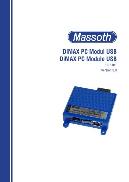
DiMAX PC Modul USB DiMAX PC Module USB - Massoth
DiMAX PC Modul USB DiMAX PC Module USB - Massoth
DiMAX PC Modul USB DiMAX PC Module USB - Massoth

Erfolgreiche ePaper selbst erstellen
Machen Sie aus Ihren PDF Publikationen ein blätterbares Flipbook mit unserer einzigartigen Google optimierten e-Paper Software.
<strong>DiMAX</strong> <strong>PC</strong> <strong>Modul</strong> <strong>USB</strong><strong>DiMAX</strong> <strong>PC</strong> <strong>Modul</strong>e <strong>USB</strong>8175101Version 3.0
1. Einleitende InformationenDas <strong>PC</strong>-<strong>Modul</strong> dient zum Programmierenund Auslesen von DCC-Decodernsowie zum Update von <strong>DiMAX</strong> Busgeräten,eMOTION Decodern und zumProgrammieren neuer Sounddateien.1.1. Funktionsumfang• Plug and Play <strong>USB</strong> Anschluss (<strong>USB</strong>2.0) zur Verbindung mit einem <strong>PC</strong>.• <strong>DiMAX</strong> Busanschluss zum Updatevon <strong>Massoth</strong> Digitalkomponenten.• 4 polige Update Buchse fürSchnellupdate von Decodern via SUSI• Trafo- oder Gleichspannungsanschlusszur Versorgung des <strong>Modul</strong>s.• Programmiergleisausgang für CV-Einstellungen, Decoderupdate undAuslesen + Programmieren von DCCDecodern1.2 Lieferumfang• <strong>DiMAX</strong> <strong>PC</strong> <strong>Modul</strong>• <strong>USB</strong> 2.0 Kabel• SUSI Update Kabel• Service CD• Bedienungsanleitung1. General InformationThe <strong>PC</strong> <strong>Modul</strong>e provides an easy wayto program and read DCC decoders aswell as an update function for <strong>DiMAX</strong>components and eMOTION decodersincluding sound file programming.1.1. Summary of Functions• Plug and Play <strong>USB</strong> interface (<strong>USB</strong>2.0) to connect to a <strong>PC</strong>.• <strong>DiMAX</strong> bus terminal to update <strong>Massoth</strong>digital components.• 4 pin Update connector for Fast-Update of decoder via SUSI• Power terminal for a transformer orDC power supply.• Output for a programming track forCV-programming, decoder updateand programming and read-outs DCCdecoder.1.2 Scope of Supply• <strong>DiMAX</strong> <strong>PC</strong> <strong>Modul</strong>e• <strong>USB</strong> 2.0 cable• SUSI update cable• Service CD• Manual3
Achtung!Das <strong>DiMAX</strong> <strong>PC</strong> <strong>Modul</strong> <strong>USB</strong> muss injeder Betriebsart via <strong>USB</strong> mit dem<strong>PC</strong> verbunden sein. Ohne diese Verbindungist kein ordnungsgemäßerBetrieb möglich.2. InbetriebnahmeSchützen sie das <strong>PC</strong> <strong>Modul</strong> vorFeuchtigkeit sowie extremen Temperaturschwankungen.Das <strong>Modul</strong> darf nuran die in der Anleitung genannte Geräteangeschlossen werden.Ein Anschluss an andere Geräte, auchwenn der Stecker dort passt, kann zurZerstörung führen.2.1. AnschlüsseDie kompletten Anschlüsse sind inAbbildung 1 eingezeichnet.2.1.1. SpannungsversorgungÜber die hinteren Klemmen (Abbildung1) wird das <strong>PC</strong> <strong>Modul</strong> mit Spannungversorgt. Der Spannungsbereich liegtzwischen 14-18 Volt Wechselspannungoder 16-24 Volt Gleichspannung.Die Polung der Versorgungspannungspielt generell keine Rolle, da das <strong>PC</strong><strong>Modul</strong> dies intern regelt. Die Spannungsversorgungsollte 2 AmpereStrom liefern können.Caution!The <strong>PC</strong> <strong>Modul</strong>e needs to be connectedto the <strong>PC</strong> via the <strong>USB</strong> interfacefor any operation mode. Withoutbeeing connected, no operation willbe available.2. Hook-UpInstall the module in a place thatprotects it from moisture and extremetemperatures. The module must onlybe connected to components that aredescribed in this manual.Connecting this unit to other componentseven if the plugs are matchingmay result in serious damage to themodule or other components.2.1. ConnectionsA complete overview of all availableconnetions is shown in illustration #1.2.1.1. Power supplyThe <strong>PC</strong> <strong>Modul</strong>e needs to be powered byan external power source (see fig. 1).A power source from 14 - 18V AC or16 - 24V is required. The polarity of thesupply voltage can be disregarded, asthe <strong>PC</strong> module regulates this internally.The power supply should be able tosupply 2 Amps current.4
Spannungsversorgung14-18 V Wechselspannung oder16-24V Gleichspannungmin. 2 AmperePower Supply14-18 V AC16-24V DCmin. 2 AmpereProgrammierausgangProgramming outputStatus-LED<strong>Massoth</strong> Busanschluss <strong>USB</strong> 2.0 Anschluss<strong>Massoth</strong> Bus Connector <strong>USB</strong> 2.0 ConnectorHigh Speed Update SchnittstelleHigh Speed Update InterfaceAbbildung 1: Anschlüsse des <strong>DiMAX</strong> <strong>PC</strong> <strong>Modul</strong>sIllustration #1: Connections of the <strong>DiMAX</strong> <strong>PC</strong> <strong>Modul</strong>eAchtung!Vertauschen Sie nicht die Spannungsversorgungsanschlüssemitdem Programmierausgang. Das<strong>Modul</strong> kann dadurch irreparabelzerstört werden.Caution!Do not mix up the power supplyconnectors with the programmingoutput. The module can be damagedirreparably.5
2.1.2. <strong>USB</strong> 2.0 AnschlussAchtung!Installieren Sie zuerst den <strong>USB</strong>Treiber mittels beiliegender CD undverbinden dann erst das <strong>PC</strong> <strong>Modul</strong>mit dem <strong>PC</strong>!Verbinden Sie mit dem beiliegendem<strong>USB</strong>-Kabel Ihren <strong>PC</strong> mit dem <strong>PC</strong> <strong>Modul</strong>.Die integrierte <strong>USB</strong> Schnittstelle wirdvon Windows ® XP - Windows ® 8automatisch erkannt und der vorherinstallierte Treiber wird für die neueSchnittstelle benutzt.Die aktuellsten Treiber erhalten Sie hier:www.ftdichip.com/Drivers/VCP.htmDer RS 232 Chip heißt FT232B.Beachten Sie beim ersten AnschlussIhres <strong>PC</strong> an das <strong>PC</strong> <strong>Modul</strong> beim Einsteckendes <strong>PC</strong> <strong>Modul</strong>s auf die Hinweiseam <strong>PC</strong>-Monitor. Hier wird nur einmaligdie virtuelle Schnittstelle angezeigtdie Ihr <strong>PC</strong> <strong>Modul</strong> in Zukunft benutzenwird. Diese müssen Sie dann im<strong>DiMAX</strong>-Update Programm oder Ihrer<strong>PC</strong>-Steuerungssoftware auswählen.2.1.2. <strong>USB</strong> 2.0 InterfaceCaution!First, install the <strong>USB</strong> drivers usingthe enclosed CD before you connectthe <strong>PC</strong> with the <strong>PC</strong> module!Connect the <strong>PC</strong> <strong>Modul</strong>e with theincluded <strong>USB</strong> cable to your <strong>PC</strong>.The integrated <strong>USB</strong> interface will beautomatically recognized by Windows ®XP - Windows ® 8 and the previouslyinstalled driver will be used for the newinterface.The latest drivers can be found here:www.ftdichip.com/Drivers/VCP.htm.The RS 232 chip type is FT232B.Note: Watch your <strong>PC</strong> monitor closelywhen connecting your 1200Z to your<strong>PC</strong> the first time. Your <strong>PC</strong> shows thevirtually port used only once. This portmust be selected in the <strong>DiMAX</strong>-Updatesoftware or your <strong>PC</strong> control software.6
3. ProgrammierungAchtung!Es stehen drei verschiedene Programmierausgängezur Verfügung.Benutzen Sie nur einen zur gleichenZeit! Alle anderen Geräte sollten abgeklemmtwerden. Nur das Produkt,das ein Update bekommen soll, darfangeschlossen sein.3.1. ProgrammiergleisausgangDer Programmiergleisanschluss ist deruniverselle Anschluss um Einstellungenund Firmwareupdates an Decoderndurchzuführen. (Abbildung 4, Seite 8)Zum Auslesen und Speichern von CVskönnen Sie unseren DCC Programmerbenutzen. Für Firmwareupdates einesDecoders benutzen Sie das <strong>DiMAX</strong>Update Programm. Achten Sie darauf,das in der Lok sich nur der zu programmierendeDecoder befindet! SchaltenSie eventuelle Spannungspuffer aus,da diese den Ablauf verfälschen oderunmöglich machen.Am Programmiergleisausgangkann wahlweise der Decoder direktangeschlossen werden, oder mit Hilfeeines Gleisstücks ein Programmiergleisgeschaffen werden, hier kann die Lokdirekt draufgestellt werden.3. ProgrammingCaution!There are three different programmingoutputs. Use only one outputat the same time! All other devicesshould be disconnected. Only theproduct selected to receive an updatemust be connected to the <strong>PC</strong> <strong>Modul</strong>e.3.1. Programming Track ConnectorThe Programming Track Connectoris the universal connector to updatedecoder settings and product firmware.(see figure 4 on page 8)In order to read and write CVs, werecommend to use the brand new DCCProgrammer, a graphical programmingtool issued earlier in 2011. Firmwareupdatesare accomplished with the <strong>DiMAX</strong>Update Tool. Make sure that only thedecoder that needs to be programmedis installed in the locomotive. Powerbuffers need to be deactivated as theywill distort the procedures.The Programming Track Connector canbe connected with the decoder directlyor a piece of track can be connected toit which allows a very easy handling:The locomotive can simply be put onthe programming track.7
3.1.1. CV ProgrammierungDie Gleisanschlüsse des Dekodersschließen Sie an die beiden rechtenSchraubklemmen an. Der Dekoderbenötigt eine Last (idealerweise derFahrzeugmotor), um ein erfolgreichesProgrammieren bestätigen zu können.Bei Programmierung eines eMOTIONS Sounddecoders brauchen Sie einenLautsprecher als Last.Das <strong>PC</strong>-<strong>Modul</strong> unterstützt die ProgrammierartenCV Bitweise lesen undCV schreiben. Sie benötigen hierfürden DCC Programmer, den Sie auf derbeiliegenden Service CD finden. DieAnleitung für den DCC Programmerkönnen Sie direkt aus dem Programmaurufen, oder von der CD starten.3.1.2. DecoderupdatesDie Gleisanschlüsse des Decodersschließen Sie an die beiden rechtenSchraubklemmen an. Der Decoderbenötigt eine Last (idealerweise derFahrzeugmotor), um ein erfolgreichesUpdate bestätigen zu können. BeiProgrammierung eines eMOTION SSounddecoders brauchen Sie einenLautsprecher als Last.Zum Update der Decoder benötigen Siedas Programm „Dimax Update V12“oder neuere Version und folgen Sie den3.1.1. CV ProgrammingConnect the track terminals of thedecoder to the right hand terminal of the<strong>PC</strong>-<strong>Modul</strong>e. An electrical load (preferablya motor) must be connected tothe decoder to receive a programmingconfirmation.In order to program an eMOTION SSounddecoder a loudspeaker needs tobe connected as inductive load.The <strong>PC</strong>-<strong>Modul</strong>e supports the programmingmethod “reading and writingbit-by-bit“ which requires the DCCProgrammer. It can be found on theenclosed CD. The DCC Programmersmanual can be started directly from theDCC Programmers menu or from theCD directly.3.1.2. Decoder UpdatesConnect the track terminals of thedecoder to the right hand terminalof the <strong>PC</strong>-<strong>Modul</strong>e. An electrical load(preferably a motor) must be connectedto the decoder to receive aprogramming confirmation. In order toupdate an eMOTION S Sounddecoder aloudspeaker needs to be connected asinductive load.To update your decoders please use the<strong>DiMAX</strong> Update V12 program and followthe instructions on your desktop screen.8
Anweisungen auf dem Bildschirm. Dieentsprechende Firmware finden Sie aufunserer Homepage im DownloadCenter.Sie müssen hierzu angemeldet sein. Dergenaue Ablauf des <strong>DiMAX</strong> Updateprogrammswird in Kapitel 4.Ein Update von <strong>Massoth</strong> eMOTIONDekodern ist nur ab Version2.0 (auslesen mit CV7) möglich!Die Programmierung erfolgt auf demProgrammiergleisanschluss des<strong>PC</strong>-<strong>Modul</strong>s. Somit kann der Decoderauch im eingebauten Zustand upgedatetwerden.ACHTUNG: Da bei diesen Updatesgroße Datenmengen übertragenwerden, muss eine sichere Verbindungzum Gleis gewährleistet sein.Wir empfehlen den Anschluss überdie Loksteckdose durchzuführen,wenn diese vorhanden ist. Ansonstenempfiehlt sich die Verwendung einesRollprüfstandes. Zum Beginn desUpdates werden ausführliche Tests derDatenübertragung vorgenommen. Solltedas Update zügig abbrechen, müssenSie für einen besseren Kontakt sorgen.The latest firmware can be found at theDownloadCenter at our website. A registrationis required. The exact updatesequence is explained in chapter 4.Only <strong>Massoth</strong> eMOTION Decoderswith firmware version 2.0 and highermay be updated! Check the decoder‘sfirmware version by reading CV7.Programming must be accomplishedvia the programming track terminal ofthe <strong>PC</strong>-<strong>Modul</strong>e. Thus the decoder maybe updated even if it is installed in alocomotive.NOTE: The data volume transferred istremendous. An optimum track contactduring this procedure is a must.We recommend to utilize the loco‘spower socket if available or the <strong>Massoth</strong>Rolling Road. The update procedurestarts with an extensive test of thecommunication line. In case the updateshuts down prematurely, a bettercontact must be provided.9
3.2. Buskomponenten3.2.1. Update von BuskomponentenBei Buskomponenten, wie zum Beispieldem <strong>DiMAX</strong> Navigator kann die aktuelleFirmware über den Busanschluss aufgespieltwerden. Verbinden Sie hierzudas Busgerät das Sie updaten möchtenmit der Bus Buchse des <strong>PC</strong> <strong>Modul</strong>s.Verwenden Sie dazu ein reguläresBuskabel. (Abbildung 2)Das <strong>Modul</strong> simuliert in diesem Modusautomatisch eine „Zentrale“ und versorgtdas zu aktualisierende Gerät überdas Buskabel.Zum Update der Busgeräte benötigenSie das Programm „Dimax Update V12“oder neuere Version und folgen Sie denAnweisungen auf dem Bildschirm. Dieentsprechende Firmware finden Sie aufunserer Homepage im Downloadcenter.Sie müssen hierzu angemeldet sein. Dergenaue Ablauf des <strong>DiMAX</strong> Updateprogrammswird in Kapitel 4 beschrieben.3.2. <strong>DiMAX</strong> Bus Components3.2.1. Updating Bus ComponentsBus components as the <strong>DiMAX</strong>Navigator can be updated with thelatest firmware version through thebus connection. In order to update adevice connect the bus device with thebus connector of the <strong>PC</strong> <strong>Modul</strong>e. Use aregular bus cable to connect it.(see figure 2)During this procedure the <strong>PC</strong>-<strong>Modul</strong>eacts as a central station and suppliesthe component which is to be updatedwith power via the bus cable.To update your bus components pleaseuse the <strong>DiMAX</strong> Update V12 programand follow the instructions on yourdesktop screen. The latest firmware canbe found at the DownloadCenter at ourwebsite. A registration is required. Theexact update sequence is explained inchapter 4.Achtung!Bei einem Update des Navigatorsmüssen Sie diesen manuell in denUpdatemodus schalten. Halten Siehierzu vor dem Einstecken desKabels die rechte STOP-Tastegedrückt.Caution!In order to update the <strong>DiMAX</strong>Navigator with the latest firmwareit needs to be set into the updatemode manually: keep the right handSTOP-key depressed as you plug inthe bus cable.10
Spannungsversorgung14-18 V Wechselspannung oder16-24V Gleichspannungmin. 2 AmperePower Supply14-18 V AC16-24V DCmin. 2 AmpereAbbildung 2: Busgeräteupdate (hier Navigator)Illustration #2: Bus components (Navigator shown)11
3.3. Update Anschlussfür schnelle DecoderupdatesMit dieser Schnittstelle wird diezukünftige Basis für ein High SpeedUpdate geschaffen. Diese Funktion wirderstmals mit dem neuen <strong>USB</strong>-<strong>PC</strong> <strong>Modul</strong>möglich sein! <strong>PC</strong> <strong>Modul</strong>e mit seriellerSchnittstelle bieten diese Funktion nicht.3.3.1. Update mit der High SpeedUpdate SchnittstelleVerbinden Sie mit dem beiliegendemSUSI Update Kabel Ihren Decoder mitSUSI Schnittstelle. Den 4poligen Steckerstecken Sie Bitte in die mittlere UpdateBuchse vorne an Ihrem <strong>PC</strong> <strong>Modul</strong>(Abbildung 3). Starten Sie das UpdateProgramm und folgen den Anweisungendes Programms.Achtung!Das High Speed Update wird miteinem zukünftigen Softwareupdate,geplant für 2012, aktiviert.3.3. Update Connector forhighspeed DecoderupdatesThis interface will offer a high speedupdate connection for decoders. Thisfeature is only available with the <strong>DiMAX</strong><strong>PC</strong> <strong>Modul</strong>e with <strong>USB</strong> Interface. Older <strong>PC</strong><strong>Modul</strong>es with a standard serial interfacedo not offer a high speed update.3.3.1. Update with the High SpeedUpdate InterfaceUse the SUSI update cable to connectthe update interface with the decoder.The 4pin plug is hooked up to the centerconnector on the <strong>PC</strong> <strong>Modul</strong>e (see illustr.3). Start the Update Program and followthe steps explained on your desktopscreen.Caution!The high speed update function willbe available with a future softwareupdate comming 2012.12
Abbildung 3: High Speed Update Schnittstelle (hier an eMOTION XLS)Illustration #3: High Speed Update Interface (shown with eMOTION XLS)13
3.4. SelbstupdateAuch für das <strong>PC</strong>-<strong>Modul</strong> ist ein Eigenupdatemöglich. Zum Update benötigenSie das Programm „Dimax Update V12“oder neuere Version und folgen Sie denAnweisungen auf dem Bildschirm. Dieentsprechende Firmware finden Sie aufunserer Homepage im DownloadCenter.Zum Selbstupdate schließen Sie nur dieSpannungsversorgung und das <strong>USB</strong>Kabel an.3.4. Self UpdateYou may update the <strong>PC</strong> <strong>Modul</strong>e aswell. Start the „Dimax Update V12“program and follow the instructions onthe screen. The current firmwareversion is available at the <strong>Massoth</strong>DownloadCenter. To update the <strong>PC</strong><strong>Modul</strong>e use the <strong>USB</strong> cable to connect itto the <strong>PC</strong> and provide a required powersource.14
4. <strong>DiMAX</strong> Update ProgrammIn den folgenden Schritten erläutertdiese Anleitung den Ablauf des Updateverfahrensmit dem Programm <strong>DiMAX</strong>Update.• Starten Sie das <strong>DiMAX</strong> Updateprogramm„Dimax Update_V12.exe“ anIhrem <strong>PC</strong>.• Bestätigen Sie den Startbildschirm desProgramms mit der Taste „Weiter“.• Nun wird die Wahl der Gerätesoftware,z.B. für den <strong>DiMAX</strong> Navigator erwartet.Klicken Sie auf die Taste „Durchsuchen“um die gewünschte oderbenötigte Datei mit Gerätesoftwareauszuwählen.• Es öffnet sich die Auswahlfunktion derGerätesoftware. Der Auswahlmoduszeigt den Inhalt des Verzeichnisses, indem das Updateprogramm gespeichertist. (Eventuell muss ein anderesVerzeichnis gewählt werden.)• Wählen Sie die Datei des gewünschtenGerätes. Der Dateiname schlüsselt dasGerät und die Version der Softwareauf.• Bestätigen Sie Ihre Wahl mit der Taste„Öffnen“.• Wählen Sie die COM-Schnittstelle, anwelcher das <strong>PC</strong> <strong>Modul</strong> über das <strong>USB</strong>-Kabel an Ihrem <strong>PC</strong> angeschlossen ist.Bestätigen Sie die Wahl der korrektenCOM-Schnittstelle mit „Weiter“.4. <strong>DiMAX</strong> Update ProgrammThe following steps will explain thegeneral steps how to perform an updatewith the <strong>DiMAX</strong> Update Program.• Start the <strong>DiMAX</strong> Update program„<strong>DiMAX</strong> Update_V12.exe“ from your<strong>PC</strong>.• Continue the starting screen in orderto continue the process• Now the firmware file you would liketo update, for example the <strong>DiMAX</strong>Navigator, needs to be selected.• Browse to the desired firmware fileand select it to update the selectedproduct. The program always startswith the directory the <strong>DiMAX</strong> UpdateProgram is located in. You may haveto change the directory.• Select the prefered file. The filenameshows the product name or itemnumber and the firmware version.• confirm your file selection• select the COM interface which isassigned to the <strong>USB</strong> <strong>PC</strong> <strong>Modul</strong>e andconfirm your selection. (Dependingon your computer spefifications theCOM port address COM 1, COM 2,etc. may vary)• The Update program will show thefirmware version and the product theselected firmware file is derterminedfor.15
HINWEIS: Die Adresse der Schnittstelle(COM 1, COM 2, etc.) kanngerätebedingt unterschiedlich ausfallen.Dies ist abhängig von der Anzahlder Schnittstellen des Pc‘s sowie derverwendeten Peripherie.• Die Software informiert Sie über dasanstehende Softwareupdate, nenntFirmwareversion und das Gerät, fürwelches die neue Software installiertwird.• Es folgen einige zusätzlicheSicherheits- bzw. Ablaufhinweise.• Das Update wird durchgeführt. DerStatusbalken wird wie gewohnt vonlinks nach rechts wachsen.• Nach dem erfolgreichen Updateerhalten Sie nochmals die Meldung,dass das Gerät erfolgreich aktualisiertwurde. Das Programm beendet sichanschließend automatisch.• Some helpful information regardingthe process and security issues areshown in the next step• The update is performed showing theprogress with a status bar• After the update has been finisheda message will be shown on yourscreen.These detailed steps show the easy operationof the <strong>DiMAX</strong> Update program.Other <strong>DiMAX</strong> or eMOTION products areupdated on the same basis.Simply connect the product that needsthe update to the <strong>PC</strong> <strong>Modul</strong>e, start the<strong>DiMAX</strong> Update program and select thecurrent firmware file. It’s that simple.Mit der Abfolge der Schritte in diesemKapitel haben Sie das SoftwareupdateIhres <strong>PC</strong> <strong>Modul</strong>s erfolgreich durchgeführt.Ebenso lassen sich auf diesemWeg weitere Digitalkomponentenupdaten. Besondere Einstellungen sinddafür nicht vorzunehmen. Schließen Siedazu lediglich Ihre Komponente an das<strong>PC</strong> <strong>Modul</strong> an und starten Sie am <strong>PC</strong> dasUpdate für die gewünschte Komponente,z.B. den <strong>DiMAX</strong> Navigator.16
5. Technische Daten• Spannungsversorgung16 - 24 V DC oder14 - 18 V AC• Stromaufnahme30 mA im Ruhezustand(externes Netzteil mit mindestens 2Ampere Leistung wird benötigt)• Programmiergleisspannung14 - 19 V (je nach Versorgung)• Programmiergleisstrommax. 1,5 Ampere• Temperaturbereich-20 - +45° C• Abmessungen (L x B x H)68 x 78 x 20 mmHinweis zur Temperatur:Um Kondenswasserbildung zu vermeiden,benutzen Sie die Elektronikbei Temperaturen unter 0°C nur, wenndiese vorher aus einem beheizten Raumkommt. Die Eigenwärme des Fahrbetriebsreicht aus um Kondenswasserbildungzu verhindern.5. Technical Specifications• Power Supply16 - 24 V DC or14 - 18 V AC• Current30 mA in idle mode(external power supply with2 Amps minimum required)• Programming Voltage14 - 19 Volts (depends on input volt.)• Programming Currentmax. 1,5 Amps• Temperature Range-20 - +45° C-4°F to +113° F• Measurements (L x W x H)68 x 78 x 20 mmCondensation:If you intend to utilize this decoderbelow freezing temperatures, makesure it was stored before in a heatedenvironment before operation to preventthe generation of condensed water. Theheat generated during operation is sufficientto prevent condensed water.17
5.1 Garantie, Reparatur, KundendienstMASSOTH gewährt die Fehlerfreiheitdieses Produkts für ein Jahr. Die gesetzlichenRegelungen können in einzelnenLändern abweichen. Verschleißteile sindvon der Garantieleistung ausgeschlossen.Berechtigte Beanstandungenwerden kostenlos behoben. Für Reparatur-oder Serviceleistungen übergebenSie das Produkt bitte Ihrem Fachhändleroder senden es direkt an den Hersteller.Unfrei zurückgesendete Sendungenwerden nicht angenommen. Eine Kopiedes Kaufbelegs wird vorausgesetzt.Für Schäden durch unsachgemäßeBehandlung oder Fremdeingriff oderVeränderung des Produkts besteht keinGarantieanspruch. Der Anspruch aufServiceleistungen erlischt unwiderruflich.Auf unserer Internetseite finden Siedie jeweils aktuellen Broschüren, Produktinformationen,Dokumentation undSoftwareprodukte rund um MASSOTH-Produkte.5.1 Warranty, Service, SupportMASSOTH warrants this product againstdefects in materials and workmanshipfor one year from the original date ofpurchase. Other countries might havedifferent legal warranty situations.Normal wear and tear, consumer modificationsas well as improper use orinstallation are not covered. Peripheralcomponent damage is not covered bythis warranty. Valid warranty claims willbe serviced without charge within thewarranty period. For warranty serviceplease return the product to you dealeror send it directly to the manufacturer.Return shipping charges are not coveredby MASSOTH. Please include yourproof of purchase with the returnedgoods.Please check our web site for up to datebrochures, product information, documentationand software updates.Errors and changes excepted.Irrtümer und Änderungen vorbehalten.18
5.2 HotlineServiceanfragen richten Sie bitte an:<strong>Massoth</strong> Elektronik GmbHMo 14:00-17:30 sowie Do 8:00-12:00FON +49 (0)6151-35077-38FAX +49 (0)6151-35077-44hotline@massoth.de5.2 HotlineFor technical support contact:<strong>Massoth</strong> Elektronik GmbH, GermanyMo 2:00-5:30 p.m. Thu 8:00-12:00 a.m.FON +49 (0)6151-35077-38FAX +49 (0)6151-35077-44hotline@massoth.deRoHSCOMPLIANT032377oDieses Produkt entspricht den CE Konformitätsrichtlinienfür elektrische Kleingeräte in der aktuellen Fassung.This unit conforms to the CE StandardsDieses Produkt ist nach den aktuellen EG Richtlinienumgangssprachlich „bleifrei“ hergestellt und damit RoHS-konform.This unit is manufactured according to the latest EG Standardsfor lead free manufacturing conforming to RoHS Standard.Entsorgen Sie das Produkt nicht im Hausmüll.Nutzen Sie bitte den dafür vorgesehenen Elektroschrott.Please dispose of according to your State regulations.Werfen Sie das Produkt nicht in offenes Feueroder durch Hitze entflammbare Brennstoffe.Do not dispose of in open fire.19
MADEINGERMANY<strong>Massoth</strong> Elektronik GmbHFrankensteiner Str. 28 · D-64342 Seeheim · GermanyFON: +49 (0)6151-35077-0 · FAX: +49 (0)6151-35077-44eMail: info@massoth.de · www.massoth.de8175101_01_2013_ML