Anwendungshinweise (PDF) - AGATHON AG Maschinenfabrik
Anwendungshinweise (PDF) - AGATHON AG Maschinenfabrik
Anwendungshinweise (PDF) - AGATHON AG Maschinenfabrik

Sie wollen auch ein ePaper? Erhöhen Sie die Reichweite Ihrer Titel.
YUMPU macht aus Druck-PDFs automatisch weboptimierte ePaper, die Google liebt.
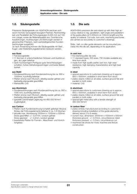
<strong>Anwendungshinweise</strong> - Säulengestelle<br />
Application notes - Die sets<br />
1.0. Säulengestelle 1.0. Die sets<br />
Präzisions-Säulengestelle von <strong><strong>AG</strong>ATHON</strong> zeichnen sich<br />
durch höchste Genauigkeit bezüglich Planheit, Rechtwinkligkeit<br />
und Parallelität der Führungssäulen (0,005 mm auf 100<br />
mm Länge), sowie der Materialqualität aus. Durchbrüche,<br />
Ausdrehungen, Ausfräsungen und Bohrungen werden in<br />
gewünschter Präzision, nach werkstattgerechten Kundenzeichnungen<br />
ausgeführt.<br />
Je nach Anwendung können die Säulengestelle mit Gleit-,<br />
Kugel- oder Rollenführungselementen bestückt werden.<br />
aus Guss<br />
Feinstanzgestelle<br />
11 Normen in unterschiedlichen Grössen und Ausführungen,<br />
ab Lager lieferbar<br />
dank hochwertigem Perlitguss gute Verschleisseigenschaften,<br />
hohes Dämpfungsvermögen und beste Belastbarkeit<br />
aus Stahl<br />
Sonderausführung nach Kundenzeichnung bis ca. 900 x<br />
1500mm, kurzfristig lieferbar<br />
Platten sind je nach Wunsch, allseitig sauber gefräst und<br />
beidseitig planparallel geschliffen<br />
Werkstoffe: C45<br />
aus Aluminium<br />
Sonderausführungen nach Kundenzeichnung bis ca. 900 x<br />
1500 mm, kurzfristig lieferbar<br />
Platten sind je nach Wunsch, allseitig sauber gefräst und<br />
beidseitig planparallel geschliffen<br />
spezielle Leichtmetall-Legierung mit 460-550 N/mm 2<br />
Zugfestigkeit<br />
aus Carbon<br />
Platten nach Kundenzeichnung komplett gefertigt inklusive<br />
Einbau der Führungselemente lieferbar in ca. 5-8 Wochen<br />
aktuelle max. Abmessung 2500mm x 1500mm x 500mm<br />
Dicke geschliffen +/- 0,01mm, rundum gefräst<br />
Dicke gepresst +/- 0,2mm, rundum gesägt<br />
bearbeitete Platten für Formen-, Maschinen- und Vorrichtungsbau<br />
<strong><strong>AG</strong>ATHON</strong>’s precision die-sets stand up with their high accuracy<br />
relative to reg. parallelism, right angle and parallelism<br />
of the guide pillars (of 0.005mm on 100mm length) and the<br />
quality of material. Cut-outs, turn-outs, machining and bores<br />
are carried out accurately to customer’s drawings.<br />
Slide-, ball- or roller guide elements can be mounted precisely<br />
into the die set, depending on its application.<br />
in cast iron<br />
fine blanking pillar die-sets<br />
11 standard types, 220 sizes, 750 models available any<br />
time from stock<br />
made from high quality perlite cast iron, high wear<br />
resistance, high damping characteristics and high load<br />
capacity<br />
in steel<br />
special executions to customers drawing up to approx.<br />
900 x 1500mm, available in short-term from stock<br />
plates cleanly milled on all sides, surface ground flat and<br />
parallel on both sides<br />
material: C45<br />
in aluminum<br />
special executions to customers drawing up to approx.<br />
900 x 1500mm, available in short-term from stock<br />
plates cleanly milled on all sides, surface ground flat and<br />
parallel on both sides<br />
special light metal alloy with a tensile strength of<br />
460-550 N/mm 2<br />
in carbon fiber<br />
plates entirely manufactured according to customer's<br />
drawing including installation of the guide elements,<br />
delivery about 5 to 8 weeks<br />
current max. dimension: 2500mm x 1500mm x 500mm<br />
thickness ground +/- 0.01mm, circumference miled<br />
thickness pressed +/- 0.2mm, circumference cut<br />
machined die shoes for mold, machine and fixture<br />
construction<br />
Änderungen vorbehalten V1<br />
01<br />
Specifications subject to change without prior notice
<strong>Anwendungshinweise</strong> - Säulengestelle<br />
Application notes - Die sets<br />
1.1. Einsatz, Vor- und Nachteile 1.1. Use, advantages and disadvantages<br />
Gussgestelle Cast iron die set<br />
Einsatz: Allgemein ~ nach Kundenzeichnung<br />
Grosse Durchbrüche für Werkstücke<br />
Materialwahl / Materialqualität<br />
Nachteil: Gewicht Disadvantage: weight<br />
Aluminiumgestelle Aluminum die set<br />
Einsatz: Schnellläuferpressen<br />
Massenproduktion über ~>1000 Hübe/min<br />
dünne Materialien<br />
Vorteil: gutes Handling<br />
flexible Abmessungen, gut bearbeitbar<br />
Gewicht<br />
Nachteil: Kosten<br />
Wärmeausdehnungskoeffizient beachten<br />
Carbongestelle Carbon fiber die set<br />
Einsatz: für höchstpräzise Stanzanwendungen oder<br />
bei hohen Hubfrequenzen<br />
geeignet für Teile mit Materialdicken von bis<br />
ca. 0,8mm (Druckbelastung ca. 0.5N/mm2 )<br />
Maschinenbau / Handlingssysteme<br />
Vorteil: geringes Gewicht: 1,65kg/dm3 schwingungsdämpfend bei hohen Hubfrequenzen<br />
(1'200 H/min), hohe Steifigkeit<br />
Ausdehnung nahe bei Null<br />
Material ist massstabil auch noch nach<br />
Jahren<br />
Temperaturbeständigkeit bis 150° resp. bis<br />
400°C Dauerbelastung<br />
Öl-, Säure- und Acetonbeständig<br />
Nachteil: Kosten<br />
Bearbeitungsmöglichkeiten<br />
spezifische Konstruktion notwendig<br />
Use: generally ~ customer<br />
drawing<br />
large breaking through for workpiece<br />
choice of material / material quality<br />
Use: high-speed presses<br />
mass production more then ~>1000<br />
strokes/min<br />
thin materials<br />
Advantage: easy handling<br />
flexible dimensions, good machining<br />
properties<br />
weight<br />
Disadvantage: cost<br />
thermal expansion coefficient<br />
Use: for extremely precise cutting applications<br />
or high stroke frequencies<br />
for parts with material thicknesses up to<br />
0.8mm (pressure load 0.5N/mm2 )<br />
machine construction / handling systems<br />
Advantage: lightweight: 1.65kg/dm3 vibration damping at high frequencies<br />
(1200 strokes/min), high rigidity<br />
expansion close to zero<br />
material is dimensionally stable even after<br />
years<br />
temperature resistant up to 150° resp.<br />
400°C for continuous load<br />
Oil, acid and acetone resistant<br />
Disadvantage: cost<br />
processing possibilities<br />
specific construction is necessary<br />
Änderungen vorbehalten V1<br />
02<br />
Specifications subject to change without prior notice
<strong>Anwendungshinweise</strong> - Säuengestelle<br />
Application notes - Die sets<br />
1.2. Auswahlkriterien 1.2. Selection criteria<br />
Folgende Kriterien können für die Materialwahl verwendet<br />
werden:<br />
Kriterium / Pt.<br />
Criterion / Pt<br />
Hubfrequenz<br />
Stroke frequency<br />
Gewicht (Handling / Pressenbelastung)<br />
Weight (handling / press load)<br />
Belastbarkeit N/mm2 (Materialdicke Endprodukt)<br />
Load N/mm2 (material thickness of final product)<br />
Bearbeitungsmöglichkeiten (Aufwand / Einschränkung)<br />
Processing options (cost / restriction)<br />
Ausdehnung / Temperaturverhalten<br />
Expansion / Temperature behavior<br />
Preis<br />
Price<br />
Preis<br />
Price<br />
Ausdehnung<br />
Expansion<br />
Auswahlkriterien für Führungselemente:<br />
siehe Kapitel 2<br />
Hubfrequenz<br />
Stroke frequency<br />
5<br />
4<br />
3<br />
2<br />
1<br />
0<br />
Bearbeitbarkeit<br />
Machinability<br />
Legende: Legend:<br />
1 (-)<br />
suboptimal<br />
tief<br />
< 100 H/min<br />
low<br />
schwer<br />
7.85 Kg/dm3 heavy<br />
tief (< 1 mm)<br />
low (< 1mm)<br />
schlecht<br />
bad<br />
viel<br />
much<br />
teuer<br />
expensive<br />
The following criteria can be used for the material selection:<br />
Gewicht<br />
Weight<br />
Belastbarkeit<br />
Load<br />
2 3 4 5 (+)<br />
optimal<br />
500 H/min<br />
Selection criteria for guide elements:<br />
see Chapter 2<br />
Grauguss EN-JL 1040 (GG25)<br />
Cast iron EN-JL 1040 (GG25)<br />
Stahl, 1.1730 (C45)<br />
Steel, 1.1730 (C45)<br />
Aluminium, 3.4365<br />
Aluminum, 3.4365<br />
Karbon<br />
Carbon fiber<br />
hoch<br />
> 1000 H/min<br />
high<br />
leicht<br />
1.65 Kg/dm3 light<br />
hoch (> 5 mm)<br />
high (> 5mm)<br />
sehr gut<br />
very good<br />
keine<br />
none<br />
preiswert<br />
Änderungen vorbehalten V1<br />
03<br />
Specifications subject to change without prior notice<br />
fair
1.3. Sonder-Säulengestelle<br />
Achsabstand mm<br />
Axis spacing mm<br />
<strong>Anwendungshinweise</strong> - Säulengestelle<br />
Application notes - Die sets<br />
<strong><strong>AG</strong>ATHON</strong> Sonder-Säulengestelle können nach Ihren Angaben<br />
bzw. Zeichnungen in jeder beliebigen Abmessung (siehe<br />
Tabelle) und Form gefertigt werden.<br />
Die Platten sind, je nach Wunsch allseitig gefräst und die<br />
Plattendicke beidseitig planparallel geschliffen.<br />
Säulendurchmesser mm<br />
Pillar diameter mm<br />
Wälzkörperdurchmesser mm<br />
Rolling element diameter mm<br />
< 100
<strong>Anwendungshinweise</strong> - Führungselemente Grundlagen<br />
Application notes - Guide elements basics<br />
2.0. <strong><strong>AG</strong>ATHON</strong> Führungselemente 2.0. <strong><strong>AG</strong>ATHON</strong> guide elements<br />
2.1. Vorteile, Herausstellungsmerkmale 2.1. Advantages, characteristics<br />
Agathon Führungselemente zeichnen sich durch hohe<br />
Verschleissfestigkeit und Präzision aus.<br />
Sie erfüllen höchste Anforderungen - dank bester<br />
Materialqualität und Oberflächengüte sowie engsten<br />
Form- und Lagetoleranzen.<br />
Die Toleranzen für Rundlauf, Zylindrizität und Konzentrizität<br />
betragen, je nach Säulendurchmesser, 0.001 bis<br />
0.005mm. Diese ermöglichen eine reproduzierbare<br />
Präzision und sind Voraussetzung um eine optimale<br />
Vorspannung (Wälzführungen), respektive ein optimales<br />
Gleitspiel (Gleitführungsbuchsen) zu erreichen.<br />
Die Säulen und Buchsen entsprechen bezüglich Form-<br />
und Nennmassen den erwähnten ISO/DIN Normen.<br />
Austauschbarkeit der Führungselemente/-Einheiten,<br />
durch einheitliche Aufnahmebohrungsdurchmesser<br />
(ISO JS4/H5) und engste Toleranzen für die entsprechenden<br />
Aussendurchmesser der Buchsen und Säule<br />
(ISO js4).<br />
Die Führungsbohrungen können deshalb, auch bei<br />
genauen Werkzeugen, bereits im Voraus ausgeführt<br />
werden. Die zylindrischen Buchsen sind mit Klebrillen am<br />
Aussendurchmesser versehen, damit diese auch bei einer<br />
leichten Uebergangspassung eingeklebt werden können<br />
(Pass-Kleben). Die glatten Säulen sind in der Qualität h3,<br />
zum Einpressen in Aufnahmebohrung ISO N5, gefertigt.<br />
Die Beschriftung der Elemente erlaubt eine eindeutige<br />
Bestimmung / Identifizierung (Rückverfolgung) und<br />
erleichtert damit den Austausch.<br />
Einfache, rasche Montage durch Zentrierhilfe (Fase f8)<br />
an Säule und Buchse.<br />
Die Säulen und Buchsen nach ISO-/DIN-Norm sind<br />
einbaukompatibel zu anderen Herstellern, da die Form<br />
und Nennmasse diesen Normen entsprechen und die<br />
Toleranzen entsprechend definiert sind.<br />
Agathon guide elements are characterized by high wear<br />
resistance and precision.<br />
They meet the highest requirements - because of<br />
best material and surface quality as well as tightest<br />
shape and position tolerances.<br />
The tolerances for run-out, cylindricity and concentricity,<br />
depending on the pillar in diameter, amount from 0.001 to<br />
0.005mm. These allow a reproducible precision and is<br />
a condition for optimal preload (rolling guides), respectively,<br />
to achieve an optimal sliding clearance (sliding<br />
guide bushes).<br />
Regarding shape and nominal dimensions, the pillars and<br />
bushes correspond to the mentioned ISO/DIN standards.<br />
Interchangeability of the guide elements/units is<br />
guaranteed through uniform location bore diameter<br />
(ISO JS4/H5) and tight tolerances for the corresponding<br />
outer diameter of the pillars and bushes (ISO js4).<br />
The guide bores may therefore be realized in advance<br />
also with accurate tools. The cylindrical bushes are<br />
provided with glue grooves on the outer diameter, so that<br />
they can be glued even with a slight transition fit (glue fit).<br />
The straight pillars are produced with the quality h3, for<br />
pressing into location bore ISO N5.<br />
The labeling of the elements allows a clear determination/identification<br />
(traceability), facilitating the<br />
exchange.<br />
Simple, rapid assembly by means of centering aid<br />
(chamfer f8) on the pillar and bush.<br />
The ISO-/DIN-standard pillars and bushes are<br />
mounting-compatible with other manufacturers, as the<br />
shape and nominal dimensions correspond with these<br />
standards and the tolerances are accordingly defined.<br />
2.2. Einsatzgebiete / Marktsegmente 2.2. Applications / Market segments<br />
Führungselemente Gruppe<br />
Guide element groups<br />
ISO-, DIN-, A<strong>AG</strong>-Norm<br />
ISO, DIN, A<strong>AG</strong> Standards<br />
Formenbau<br />
Mold construction<br />
AFNOR-Norm<br />
AFNOR Standards<br />
Inch Abmessungen<br />
Inch program<br />
Sonderausführungen<br />
Special execution<br />
Stanz-Werkzeugbau<br />
Punching tools<br />
Marktsegmente<br />
Market segments<br />
Spritzgussformenbau Maschinen-, Apparate- und Vorrichtungsbau<br />
Injection molds Machine, apparatus and device construction<br />
√ √ √<br />
√<br />
√<br />
Änderungen vorbehalten V1<br />
05<br />
Specifications subject to change without prior notice<br />
√<br />
√ √ √
2.3. Bestimmen der Führungsart und<br />
spezifische Eigenschaften<br />
2.3. Determine the type of guidance<br />
and specific properties<br />
2.3.1. Auswahlhilfe für Führungsart 2.3.1. Selection tool for guidance type<br />
Preis<br />
Price<br />
Austauschbarkeit<br />
Interchangeability<br />
Kriterium / Pt.<br />
Criterion / Pt<br />
Hubgeschwindigkeit* (m/min),<br />
Hubfrequenz (Hübe/min)<br />
Stroke speed* (m/min),<br />
Stroke frequency (strokes/min)<br />
Momentbelastung/Kraft<br />
Moment load/Force<br />
Präzision<br />
Precision<br />
Verschleiss (Führung)<br />
Wear (guide)<br />
Austauschbarkeit<br />
Interchangeability<br />
Preis<br />
Price<br />
Hubgeschwindigkeit* (m/min), Hubfrequenz (Hübe/min)<br />
Stroke speed* (m/min), Stroke frequency (strokes/min)<br />
5<br />
1 (-) 2 3 4 5 (+)<br />
< 30m/min,<br />
~ 300H/min<br />
keine<br />
none<br />
gering (Spiel)<br />
poor (play)<br />
viel<br />
much<br />
Aufwand gross<br />
great effort<br />
teuer<br />
expensive<br />
* Beim Berechnen der Hubgeschwindigkeit ist zu beachten,<br />
dass bei der Wälzführung der Käfig nur den halben Hub/Weg<br />
zurücklegt!<br />
<strong>Anwendungshinweise</strong> - Führungselemente Grundlagen<br />
Application notes - Guide elements basics<br />
4<br />
3<br />
2<br />
1<br />
0<br />
Verschleiss (Führung)<br />
Wear (guide)<br />
Legende: Legend:<br />
~ 60m/min,<br />
~ 600H/min<br />
Momentbelastung/Kraft<br />
Moment load/Force<br />
Präzision<br />
Precision<br />
~ 90m/min,<br />
~ 900H/min<br />
mittel<br />
average<br />
Gleitführung (Punkt 3.2.)<br />
Slide guide (point 3.2.)<br />
Kugelführung<br />
Ball guide<br />
Rollenführung Agathon Rolle<br />
Roller guide Agathon roller<br />
Rollenführung Profilrolle<br />
Roller guide Profile roller<br />
~120m/min,<br />
~ 1'200H/min<br />
< 150m/min,<br />
> 1'500H/min<br />
hoch<br />
high<br />
hoch<br />
high<br />
wenig<br />
little<br />
Aufwand klein<br />
small effort<br />
preiswert<br />
fair<br />
* When calculating the stroke speed it is important to note<br />
that with the roller guide, the cage only travels half the stroke/<br />
way!<br />
Änderungen vorbehalten V1<br />
06<br />
Specifications subject to change without prior notice
<strong>Anwendungshinweise</strong> - Führungselemente Grundlagen<br />
Application notes - Guide elements basics<br />
2.3.2. Gleitführungen 2.3.2. Sliding guides<br />
Gleitführungen werden für relativ lange axiale -, respektive<br />
oszillierende Kombinationsbewegungen (axial/radial) und<br />
als Verriegelungssysteme eingesetzt. Die Gleitgeschwindigkeit<br />
ist auf 30 m/min limitiert.<br />
Die hoch präzisen Gleitführungen von Agathon bestehen<br />
aus einer Führungssäule und einer entsprechenden<br />
Gleitbuchse. Enge Fertigungstoleranzen garantieren ein<br />
minimales Gleitspiel der Führung und damit eine für<br />
Gleitführungen hohe Führungsgenauigkeit.<br />
Je nach Überlappung von Säule und Buchse können<br />
relativ hohe radiale -, respektive überlagerte Belastungen<br />
(Radial- und Momentbelastung) aufgenommen werden. Bei<br />
geringer radialer Belastung kann mit der Säule aus der<br />
Buchse ausgefahren werden (Flächenpressung beim<br />
Eintritt). Für den Eintritt in die Buchse müssen die Längsachsen<br />
von Säule und Buchse zueinander vorzentriert<br />
sein, z.B. durch die Presse oder Spritzgiessmaschine.<br />
Je nach Anforderungen und Anwendung werden bronzeplattierte<br />
Stahlbuchsen (2.3.2.1) oder Gleitbuchsen aus<br />
Sintereisen (2.3.2.2.) eingesetzt.<br />
Einheitliche Aufnahmedurchmesser und Toleranzen (ISO<br />
js4) garantieren die Austauschbarkeit zu allen Buchsen der<br />
ISO-/DIN-Norm von Agathon.<br />
Sliding guides are used for relatively long axial, respectively,<br />
combined oscillating movements (axial/radial) and as<br />
locking system. The sliding speed is limited to 30m/min<br />
The high precision slide guides of Agathon consist of a<br />
guide pillar and a corresponding guide bush. Narrow<br />
manufacturing tolerances ensure a minimal sliding clearance<br />
of the guide and thus a sliding guide for high<br />
precision guidance.<br />
Depending on the overlap of pillar and bush, relatively high<br />
radial, respectively, superimposed loads (radial and<br />
moment loads) can be absorbed. At low radial load, the<br />
pillar can be moved out of the bush (surface pressure at<br />
the entrance). For the entry into the bush, the longitudinal<br />
axes of the pillar and bush must be pre-centered to each<br />
other, e.g. in the press or injection molding machine.<br />
Depending on application requirements, bronze plated<br />
steel bushes (2.3.2.1) or sintered iron slide bushes<br />
(2.3.2.2.) are used.<br />
Uniform location diameter and tolerances (ISO js4)<br />
guarantee the interchangeability of all Agathon ISO/DIN<br />
Standards bushes.<br />
Änderungen vorbehalten V1<br />
07<br />
Specifications subject to change without prior notice
2.3.2.1. Bronzeplattierte Stahlbuchsen - Normen 7011,<br />
7014, 7161, 7162, 7164<br />
a) Einsatz a) Application<br />
Anwendungen im Stanzwerkzeugbau (z.B. Transferwerkzeuge),<br />
Maschinen-, Apparate- und Vorrichtungsbau sowie,<br />
bei geeigneten Schmierstoffen, im Kunststoff-Spritzgiessformenbau.<br />
Für lange Hubbewegungen und eventuellem Ausfahren der<br />
Säule aus der Buchse, bei einer limitierten Gleitgeschwindigkeit<br />
von max. 30 m/min (d.h. tiefe bis mittlere Hubfrequenzen).<br />
<strong>Anwendungshinweise</strong> - Führungselemente Grundlagen<br />
Application notes - Guide elements basics<br />
b) Eigenschaften b) Properties<br />
Die gehärteten Stahlgleitführungsbuchsen, mit bronzeplattierter<br />
Lauffläche, sind mit einer in sich geschlossenen,<br />
achterförmigen Schmiernute versehen. Diese<br />
garantiert eine optimale Schmierung auch bei kurzen<br />
Bewegungen. Für die periodische Schmierung mit Fett<br />
(< = 12m/min) oder Oel (> 12m/min) sind die Buchsen, je<br />
nach Ausführung, mit Schmiernippel oder einer Schmierbohrung<br />
versehen. Je nach Hubfrequenz und Hub muss<br />
mehrmals pro Tag geschmiert werden. Für solche<br />
Anwendungen empfiehlt sich ein zentrales Schmiersystem.<br />
Die Bronze Schichtdicke von 0.25 bis 0.3mm erlaubt ein<br />
optimales Einlaufen, ohne dass zu viel Spiel entsteht und<br />
garantiert gute Notlaufeigenschaften.<br />
Der gehärtete Stahlmantel verhindert, dass sich die<br />
Buchse bei hoher Kantenpressung deformiert.<br />
Bei optimaler Auslegung von Führungsspiel, Belastung<br />
und Wärmeableitung sind Gleitgeschwindigkeiten von bis<br />
zu 30m/min möglich.<br />
Das theoretische Gleitspiel beträgt mit einer Standardsäule,<br />
je nach Säulendurchmesser, min. 0.003 bis max.<br />
0.017mm.<br />
c) Ausführung c) Execution<br />
Die bronzeplattierten Gleitbuchsen werden standardmässig<br />
in den Ausführungen glatt zum Einkleben (Passkleben)<br />
und mit Bund angeboten. Andere Formen/Abmessungen<br />
sind auf Anfrage erhältlich.<br />
Bei Bedarf kann das Gleitspiel durch honen (kreuzschleifen)<br />
vergrössert werden. Dazu muss die Buchse als<br />
Sonderausführung mit dem gewünschten Spiel / Toleranz<br />
bestellt werden. Bei engem oder genau definiertem<br />
Gleitspiel muss die Führung gepaart werden. Speziell<br />
gepaarte Elemente sind mit einer einheitlichen Zusatznummer<br />
versehen und werden als Führungseinheit<br />
geliefert. Wenn die Buchse am Innendurchmesser<br />
verändert wurde, ist diese mit einem + versehen. Solche<br />
Elemente dürfen nicht einzeln ersetzt werden.<br />
2.3.2.1. Bronze plated steel bushes - Standards 7011,<br />
7014, 7161, 7162, 7164<br />
Applications in the punching tool (e.g. transfer tools), machine,<br />
apparatus and device construction, as well as, with<br />
appropriate lubricants, in the plastic injection mold construction.<br />
For long strokes and possible extension of the pillar out of<br />
the bush, with a limited sliding speed of 30 m/min (i.e. low to<br />
medium stroke frequencies).<br />
The hardened steel slide guide bushings, with bronze<br />
plated contact surface are provided with a self-contained,<br />
eighth-shape greasing groove. This guarantees optimum<br />
lubrication even during short movements. For periodic<br />
lubrication with grease ( 12 m/min),<br />
the bushes, depending on the version, are provided with<br />
grease nipple or greasing hole. Depending on the stroke<br />
rate and stroke, it needs to be lubricated more than once<br />
per day. For such applications, we recommend a central<br />
lubrication system.<br />
The bronze layer thickness of 0.25 to 0.3mm allows<br />
optimum running-in, without too much play, and guarantees<br />
good emergency running properties.<br />
The hardened steel shell prevents the bush from deforming<br />
at high edge pressure.<br />
With optimum design of guiding clearance, load and heat<br />
dissipation, sliding speeds of up to 30m/min are possible.<br />
With a standard pillar and depending on the pillar<br />
diameter, the theoretical sliding clearance amounts to min.<br />
0.003 and max. 0.017mm.<br />
Schmierfilter<br />
Lubrication filter<br />
Bronzeschicht<br />
Bronze layer<br />
Stahlmantel<br />
Steel shell<br />
As standard, the bronze plated sliding bushes are<br />
available with straight design to be glued (glue fit) and with<br />
flange. Other types/sizes are available on request.<br />
When necessary, the sliding clearance can be increased<br />
by honing (cross-grinding). For this, the bush must be<br />
ordered as special execution with desired clearance/<br />
tolerance. In the case of narrow or precisely defined<br />
sliding clearance, the guide must be paired. Especially<br />
paired elements are provided with the same additional<br />
number and delivered as guidance unit. If the bush has<br />
been changed on the inside diameter, it is marked with a<br />
+ sign. Such elements can not be replaced individually.<br />
d) Wartung/Schmierung d) Maintenance and lubrication<br />
Siehe Punkt 2.5. Schmierstoffe See Section 2.5. Lubricants<br />
Änderungen vorbehalten V1<br />
08<br />
Specifications subject to change without prior notice
2.3.2.2. Stahl-Sinterbuchsen, selbstschmierend<br />
Normen 7020, 7021<br />
a) Einsatz a) Application<br />
Die gehärteten Stahlsinterbuchsen sind selbstschmierend<br />
und damit für Anwendungen geeignet, bei denen eine<br />
Langzeitschmierung gefordert wird und der Hubweg<br />
relativ kurz ist. Typische Anwendungen finden sich im<br />
Stanzwerkzeugbau sowie Maschinen-, Apparate- und<br />
Vorrichtungsbau (oszillierende Kombinationsbewegungen).<br />
Dank des extrem geringen Gleitspiels sind diese<br />
Buchsen auch für Verriegelungssysteme geeignet. Die<br />
Gleitgeschwindigkeit ist auf max. 30m/min limitiert (d.h.<br />
tiefe bis mittlere Hubfrequenzen).<br />
Für den Einsatz in Kunststoffspritzgiessformen ist die Einsatztemperatur<br />
des Schmierstoffes zu beachten (Imprägnierungsöl:<br />
-12°C bis +90°C).<br />
<strong>Anwendungshinweise</strong> - Führungselemente Grundlagen<br />
Application notes - Guide elements basics<br />
2.3.2.2. Steel sintered bushes, self lubricating - Standards<br />
7020, 7021<br />
The hardened steel sintered bushes are self-lubricating<br />
and thus suitable for applications where a long-term<br />
lubrication is required and the stroke is relatively short.<br />
Typical applications are found in the punching tool construction<br />
as well as machine, apparatus and device<br />
construction (oscillating combined movements). Thanks to<br />
the extremely low sliding clearance, these bushes are also<br />
suitable for locking systems. The sliding speed is limited<br />
to max. 30m/min (i.e. low to medium stroke frequencies).<br />
For applications in plastic injection molds, the working temperature<br />
of the lubricant must be observed (impregnation oil:<br />
from -12°C up to +90°C).<br />
b) Eigenschaften/Funktion b) Properties/Function<br />
Die Gleitbuchsen sind mit Öl getränkt. Das Porenvolumen<br />
beträgt ca. 20% des Gesamtvolumens. Die Ölmenge<br />
reicht im allgemeinen für die Lebensdauer der Gleitbuchse.<br />
Da die Poren miteinander verbunden sind, kann der<br />
flüssige Schmierstoff zirkulieren. Zwischen der Buchse<br />
und der Säule baut sich bei Betrieb ein hydrodynamischer<br />
Schmierfilm auf, erzeugt durch Kapillarwirkung, elastische<br />
Deformation und Wärmeausdehnung. Mit zunehmender<br />
Betriebsdauer steigt die Temperatur im Lager. Da die<br />
Wärmeausdehnung des Öls größer ist, als die des<br />
Lagermetalls, wird weiteres Öl in den Lagerspalt gepresst.<br />
Bei Stillstand nehmen die Poren das Öl wieder auf.<br />
Normalerweise ist keine Zusatzschmierung notwendig.<br />
Bei extremen Betriebsverhältnissen (hoher Belastung,<br />
erhöhte Temperatur, längerer Hub) ist eine solche<br />
angebracht. Das Öl wird ohne Druck zugeführt (ev. über<br />
zusätzliche Bohrung in der Buchsenwand). Durch die<br />
Kapillarkraft wird es in die Poren gesaugt und ersetzt<br />
verlorengegangenes Öl. Eine Zusatzschmierung mit Fett<br />
ist möglich (z.B. bei längerem Hub). Fett kann auch zur<br />
Initialschmierung oder als Schmierreserve angewendet<br />
werden (Depotfett).<br />
Durch die enge Toleranz beim Innendurchmesser beträgt<br />
das theoretische Gleitspiel, in Kombination mit einer<br />
Standardsäule und je nach Säulendurchmesser, min.<br />
0.002 bis max. 0.012mm.<br />
Durch das Härten der Sinterbuchse entsteht sehr wenig<br />
Abrieb. Die hohe Verschleissfestigkeit garantiert, dass die<br />
Formgenauigkeit und das Gleitspiel lange erhalten<br />
bleiben.<br />
The bushes are impregnated with oil. The pore volume is<br />
about 20% of the total volume. The amount of oil is<br />
generally sufficient for the life of the bush. Because the<br />
pores are interconnected, the liquid lubricant can circulate.<br />
A hydrodynamic lubricating film, produced by<br />
capillary action, elastic deformation and thermal expansion,<br />
builds up between the bush and the pillar. With<br />
increasing operating time the temperature rises in the<br />
bearing. Because the thermal expansion of the oil is<br />
greater than that of the bearing metal, more oil is pressed<br />
into the bearing gap. At standstill, the pores absorb the oil<br />
again. Normally, no additional lubrication is necessary. For<br />
extreme operating conditions (high load, high temperature,<br />
longer stroke) is such one appropriate. The oil is<br />
supplied without pressure (possibly through an additional<br />
hole in the bush wall). Through the capillary force, the oil is<br />
sucked into the pores and replaces the lost oil. An<br />
additional lubrication with grease is possible (e.g. for<br />
longer stroke). Fat can also be used for initial lubrication or<br />
lubrication reserve (depot fat).<br />
Due to the close tolerance of the inner diameter, the<br />
theoretical sliding clearance amounts to min. 0.002 and<br />
max. 0.012mm, in combination with a standard pillar and<br />
depending on pillar diameter.<br />
Hardening the sinter bush results in very little wear. The<br />
high wear resistance guarantees a long time accuracy of<br />
shape and sliding play.<br />
Sintereisen, mit Öl getränkt<br />
Sinter iron, impregnated with oil<br />
Änderungen vorbehalten V1<br />
09<br />
Specifications subject to change without prior notice
c) Ausführung c) Execution<br />
Die Gleitbuchsen werden in der Ausführung glatt zum<br />
Einkleben (Passkleben) angeboten und dürfen nicht eingepresst<br />
werden.<br />
Bei engem oder genau definiertem Gleitspiel muss die Führung<br />
gepaart werden. Speziell gepaarte Elemente sind mit<br />
einer einheitlichen Zusatznummer versehen und werden als<br />
Führungseinheit geliefert. Wenn die Buchse am Innendurchmesser<br />
verändert wurde, ist diese mit einem + versehen.<br />
Solche Elemente dürfen nicht einzeln ersetzt werden.<br />
Nachbearbeitung:<br />
Um die einwandfreie Funktion von Sinterbuchsen nicht zu<br />
beeinträchtigen, ist eine Nachbearbeitung wenn möglich<br />
zu vermeiden. Die Gleitfläche darf nicht durch Reiben oder<br />
schleifen bearbeitet werden, da sonst die öltransportierenden<br />
Poren verstopft werden. Die Aussenseite der Buchse<br />
kann theoretisch beliebig bearbeitet werden (nur wenn keine<br />
Zusatzschmierung von aussen vorgesehen ist, da die Poren<br />
dafür auch aussen offen bleiben müssen). Da der dabei<br />
auftretende Ölverlust ergänzt werden muss, sollte dieser<br />
Prozess nur vom Hersteller durchgeführt werden.<br />
<strong>Anwendungshinweise</strong> - Führungselemente Grundlagen<br />
Application notes - Guide elements basics<br />
The sliding bushes are available with straight design to be<br />
glued (glue fit) and they must not be pressed-in.<br />
In the case of narrow or precisely defined sliding clearance,<br />
the guide must be paired. Especially paired elements are<br />
provided with the same additional number and delivered as<br />
guidance unit. If the bush has been changed on the inside<br />
diameter, it is marked with a + sign. Such elements can not<br />
be replaced individually.<br />
Reworking:<br />
In order not to impair the proper function of sintered bushes,<br />
a reworking should be avoided when ever possible.<br />
The sliding surface can not be processed by rubbing or<br />
grinding, otherwise the oil transporting pores clog. Any processing<br />
can theoretically be used on the outside of the bush<br />
(only if no additional lubrication is provided from outside,<br />
since the pores must also remain open to the outside). Because<br />
the occurring loss of oil must be added, this process<br />
should be executed by the manufacturer.<br />
d) Wartung/Schmierung d) Maintenance/Lubrication<br />
Siehe Punkt 2.5. Schmierstoffe See Section 2.5. Lubricants<br />
Änderungen vorbehalten V1<br />
10<br />
Specifications subject to change without prior notice
<strong>Anwendungshinweise</strong> - Führungselemente Grundlagen<br />
Application notes - Guide elements basics<br />
2.3.3. Wälzführungen 2.3.3. Rolling guides<br />
Wälzführungen sind spielfrei und werden eingesetzt,<br />
wenn hohe Präzision / Führungsgenauigkeit benötigt<br />
wird, oder eine Gleitführung, aufgrund von Schmierproblemen,<br />
nicht mehr genügen kann. Wälzführungen sind<br />
wartungsarm und können, je nach Belastung / Einsatz,<br />
auch ohne Schmierstoff betrieben werden. Dabei wird die<br />
Lebensdauer reduziert.<br />
Das leichtgängige Laufverhalten erleichtert Einpassarbeiten<br />
und den Zusammenbau eines Werkzeuges.<br />
Wälzführungen eignen sich deshalb auch, wenn eine<br />
geringe Verschiebekraft gefordert wird.<br />
Der Hubweg ist bei einer vorgespannten Wälzführung,<br />
ohne Käfighalte/-positioniersystem, durch die Buchsenlänge<br />
limitiert (siehe Punkt 2.3.3.1.).<br />
Die lange Lebensdauer der Agathon Wälzführungen<br />
wird erreicht durch spezielle Einlaufgeometrien an<br />
Säule und Buchse, in Kombination mit einer patentierten<br />
Verstemmung, sowie entsprechenden Formen für<br />
die Aufnahmetasche (patentiert), welche ein exaktes,<br />
definiertes Spiel und einen perfekten Halt der Wälzkörper<br />
im Käfig garantieren (siehe Punkt 2.3.3.2.).<br />
Die Wälzkörper sind in axialer Richtung versetzt<br />
angeordnet, so dass diese nicht auf der gleichen Linie,<br />
hintereinander laufen.<br />
Eine hohe Belastbarkeit / Führungssteifigkeit wird<br />
erreicht dank optimaler Bestückung/Anordnung der<br />
passenden Wälzkörper und einer entsprechend<br />
abgestimmten Vorspannung (siehe Punkt 2.3.3.3.).<br />
Rolling guides are free from play and used where high<br />
precision/ accuracy of guidance is needed, or where<br />
one slide guide, due to lubrication problems, is no longer<br />
sufficient. Rolling guides require little maintenance and<br />
can be operated, according to load/application, without<br />
lubricant. This reduces the lifespan.<br />
The smooth-running behavior facilitates trimming work<br />
and the assembly of a tool. Rolling guides are suitable<br />
therefore even if a small displacement force is required.<br />
The stroke is limited by a preloaded rolling guide, without<br />
cage retaining / positioning system, through the bushing<br />
length (see Section 2.3.3.1.).<br />
The long lifespan of the Agathon rolling guides is<br />
achieved by means of special inlet geometries on the<br />
pillar and bush, in combination with a patented<br />
staking, as well as corresponding shapes for the<br />
receiving pockets (patented), which guarantee an exact,<br />
defined play and a perfect stability of the rolling elements<br />
in the cage (see Section 2.3.3.2.).<br />
The rolling elements are arranged offset in the axial<br />
direction so that those which are not on the same line,<br />
run one after the other.<br />
A high load capacity/guiding stability is achieved due<br />
to optimal placement/arrangement of suitable<br />
rolling elements and a corresponding matching<br />
preload (see Section 2.3.3.3.).<br />
Änderungen vorbehalten V1<br />
11<br />
Specifications subject to change without prior notice
2.3.3.1. Einlaufgeometrie an Säule und Buchse,<br />
kontrolliertes Spiel der Wälzkörper im Käfig<br />
Säulen und Buchsen werden mit optimierten Einlaufgeometrien<br />
versehen. Diese sind möglichst kurz ausgebildet,<br />
damit nicht unnötig Führungslänge (Vorspannungsbereich)<br />
verloren geht. In Kombination mit einem definierten radialen<br />
Spiel der Wälzkörper im Käfig, wird dadurch der Schlag<br />
auf den Käfig beim Eintreten in die Vorspannung massiv<br />
reduziert. Damit wird die Lebensdauer des Käfigs (Führung)<br />
signifikant erhöht und die Gefahr, dass der Käfig wandert,<br />
deutlich verkleinert.<br />
Die spezielle, patentierte Verstemmung der Wälzkörper<br />
im Käfig (Kugeln sind z.B. am gesamten Umfang gehalten)<br />
erhöht die Haltekraft und verkleinert das Risiko, dass die<br />
Wälzkörper herausgeschlagen werden.<br />
Die Agathon Wälzführungen erfüllen damit die Anforderungen,<br />
wie sie auf neuen Hochleistungsstanzautomaten (bis<br />
über 2'500 Hüben/min), oder beim horizontalen Einsatz im<br />
Spritzgussformenbau, auftreten können.<br />
Nachfolgende Skizze veranschaulicht die auftretenden<br />
Kräfte auf Buchse, Käfig und Säule beim Einfahren in die<br />
Vorspannung.<br />
2.3.3.1. Inlet geometry on pillar and bush, controlled<br />
play of the rolling guide in the cage<br />
Pillars and bushes are provided with optimized inlet<br />
geometries. These are designed as short as possible, to<br />
avoid unnecessary guide length (preload) getting lost. In<br />
combination with a defined radial play of the rolling elements<br />
in the cage, the impact on the cage when entering the<br />
preload is greatly reduced. Thus significantly increases the<br />
lifespan of the cage (guide) and greatly reduces the risk of<br />
cage creeping.<br />
The special, patented staking of the rolling elements<br />
in the cage (e.g. balls are held on the entire circumference)<br />
increases the holding power and reduces the risk that the<br />
rolling elements are ejected.<br />
The Agathon rolling guides fulfill the same requirements,<br />
as they occur on the new high-performance stamping<br />
machines (up to over 2500 strokes/min), or in horizontal applications<br />
in injection mold making.<br />
The following diagram illustrates the forces applied on the<br />
bushing, cage and pillar when entering into the preload.<br />
Verstemmung der Kugeln (Patent) Staking of the balls (patent)<br />
Vorteile:<br />
Kugel wird am gesamten Umfang gehalten.<br />
Bessere Haltekraft der Kugel.<br />
Reduziert das radiale Kugelspiel.<br />
Schlag beim Eintreten des Wälzkörpers in die Vorspannung<br />
ist wesentlich kleiner.<br />
<strong>Anwendungshinweise</strong> - Führungselemente Grundlagen<br />
Application notes - Guide elements basics<br />
Aktuell<br />
Actual<br />
S K<br />
F F<br />
F F<br />
S K S K<br />
S K = Kugelspiel<br />
S K = Ball clearance<br />
Advantages:<br />
The ball is held on its entire circumference.<br />
Better retention force of the balls.<br />
Reduced radial ball clearance.<br />
The impact is considerably smaller when the balls enter<br />
into the preload.<br />
Änderungen vorbehalten V1<br />
12<br />
Specifications subject to change without prior notice<br />
S K<br />
Alt<br />
Old<br />
Vorspannung<br />
Preload
Verstemmung der Rolle und Haltetasche (Patent) Staking of the rollers and retaining pockets (patent)<br />
Aktuelle Ausführung<br />
Actual execution<br />
Vorteile:<br />
Keine Reibung durch den Käfig auf den Abwälzzonen<br />
der Rolle.<br />
Geringere Reibung auf den Berührungsflächen zwischen<br />
Rolle und Haltetasche, dank besserer Oberflächengüte.<br />
Definiertes, optimiertes Spiel der Rolle im Käfig, Rolle<br />
wird nur noch von aussen verstemmt.<br />
Höhere Formtreue der Haltetasche und genauere<br />
Übereinstimmung der Achsen von Käfig und Haltetasche.<br />
<strong>Anwendungshinweise</strong> - Führungselemente Grundlagen<br />
Application notes - Guide elements basics<br />
Alte Ausführung<br />
Old execution<br />
Advantages:<br />
No friction with the cage on the rolling zone of the roller.<br />
Lower friction on the contact surfaces between the<br />
roller and retaining pocket, thanks to improved surface<br />
quality.<br />
Defined, optimized play of the roller in the cage, the<br />
roller is only staked from the outside.<br />
Higher dimensional stability of the retaining pocket<br />
and more exact match of the axes of the cage and<br />
holding pocket.<br />
Änderungen vorbehalten V1<br />
13<br />
Specifications subject to change without prior notice
2.3.3.2. Hubweg des Käfigs / Buchsen Auslegung 2.3.3.2. Cage travel / Bushes design<br />
Bedingt durch die Vorspannung macht der Käfig zwangsläufig<br />
(kraftschlüssig) nur den halben Arbeitshub/-Weg<br />
(siehe nachfolgende Skizze). Bei der Auslegung der Führung<br />
(Käfig-/Buchsenlänge) muss dies berücksichtigt werden.<br />
½ Drehung (½ Umfang)<br />
des Wälzkörpers ergibt<br />
eine Verschiebung von<br />
der Säule zur Buchse von<br />
1x dem Umfang<br />
Beispiel: Example:<br />
Um ein Käfigwandern-, respektive, je nach Belastung, eine<br />
Überlastung der Wälzkörper zu vermeiden, sollte der Käfig<br />
zu ca. 50% in der Buchse / Vorspannung verbleiben.<br />
D.h. vereinfacht:<br />
Buchsenlänge = Hubweg<br />
Die verbleibenden 50% Wälzkörper müssen in diesem Fall<br />
die Belastung aufnehmen.<br />
Wenn die radiale Kraft oder Momentbelastung auf die<br />
Führung beim Aus-/Einfahren in die Vorspannung gering ist<br />
(radiale Traglastverteilung der Kräfte auf die in der Vorspannung<br />
verbleibenden Wälzkörper), kann aus der Buchse<br />
ausgefahren werden, sofern ein Käfigrückhalte/-positioniersystem<br />
verwendet wird.<br />
<strong>Anwendungshinweise</strong> - Führungselemente Grundlagen<br />
Application notes - Guide elements basics<br />
½ Drehung Kugel<br />
½ rotation of ball<br />
Buchse/Käfig - Vorspannung<br />
Bush/Cage - Preload<br />
F<br />
W2' W1<br />
1 Hub Säule oder Buchse<br />
1 stroke - Pillar or bush<br />
Due to the preload, the cage inevitably only moves half of<br />
the working stroke/travel (see diagram below). This must be<br />
taken into account when designing the guide (cage/bush<br />
length).<br />
½ Hub<br />
½ stroke<br />
W2 W1'<br />
Buchse<br />
Bush<br />
Wälzkörper<br />
Rolling element<br />
To avoid a cage creeping, respectively, depending on load,<br />
an overloading the rolling elements, the cage should remain<br />
around 50% in the bush/preload.<br />
I.e. simplified:<br />
Bush length = Stroke travel<br />
In this case, the remaining 50% of the rolling element must<br />
take up the load.<br />
If radial force or moment load on the guide is low when<br />
moving in/out of the preload (radial load distribution of the<br />
forces on the rolling elements remaining in the preload), the<br />
cage can be moved out of the bush as long as our cage<br />
retaining / positioning system is used.<br />
Änderungen vorbehalten V1<br />
14<br />
Specifications subject to change without prior notice<br />
Säule<br />
Pillar<br />
Käfig ½ Hub<br />
Cage ½ stroke<br />
Buchse - 1 Hub<br />
Bush - 1 Stroke<br />
½ rotation (½ the circumference)<br />
of the rolling<br />
element results in a shift,<br />
from the pillar to the bush,<br />
of one time the circumference<br />
Vorspannung ½<br />
Preload ½<br />
F
2.3.3.3. Vorspannung, Eigenschaften / Federkennlinie<br />
von Wälzkörpern, Lastverteilung<br />
Die Vorspannung ermöglicht eine spielfreie Führung,<br />
verhindert, dass der Käfig wandert (Stick-Slip- Effekt) und<br />
beeinflusst die Steifigkeit, Belastbarkeit, Gängigkeit und<br />
Lebensdauer der Führung. Diese Eigenschaften stehen<br />
teilweise im Gegensatz zueinander. Zum Beispiel erhöht<br />
eine hohe Vorspannung die Steifigkeit, reduziert jedoch<br />
die Belastbarkeit, Gängigkeit und je nach Belastung die<br />
Lebensdauer der Führung.<br />
Durch die Verwendung von engsten, definierten Toleranzen /<br />
Massen sowie höchster Oberflächengüte an Säule, Buchse<br />
und Wälzkörper wird bei den Katalogartikeln eine optimale<br />
Vorspannung, für ein breites Einsatzgebiet, erreicht.<br />
Je nach verwendeten Wälzkörpern (z.B. Rollentyp), oder für<br />
besondere Anwendungen (Mess-Systeme), sind die Führungseinheiten<br />
gepaart, respektive müssen diese gepaart<br />
werden!<br />
2.3.3.3. Preload, Features / Spring characteristic of<br />
rolling elements, Load distribution<br />
The preload allows a backlash-free guidance, prevents that<br />
the cage moves (stick-slip effect) and affects the stiffness,<br />
load capacity, smooth operation and lifespan of the guide.<br />
These properties are partly in contrast to one another. E.g.<br />
a high preload increases the stiffness, but reduces the load<br />
capacity, smooth operation and depending on the load, the<br />
life of the guide.<br />
For the catalog items optimum preload is achieved, for a<br />
wide range of applications, through the use of tightest,<br />
defined tolerances/dimensions and high surface quality on<br />
pillar, bush and rolling elements.<br />
Depending on the type rolling elements (e.g. roller type), or<br />
for special applications (measuring systems), the guiding<br />
units are paired, respectively, must be paired!<br />
a) Definition der Vorspannung a) Definition of the preload<br />
Unter Vorspannung versteht man die rechnerische Differenz<br />
vom Innendurchmesser der Buchse (d2), minus 2x den<br />
Wälzkörperdurchmesser (d3), abzüglich Säulendurchmesser<br />
(d1). Das Resultat im Minusbereich (μm) wird als Vorspannung<br />
(bezogen auf den Durchmesser) bezeichnet. D.h. die<br />
einzelnen Komponenten müssen durch Einfederung diesen<br />
Wert kompensieren. Die maximale Materialbelastbarkeit<br />
bis zur bleibenden Deformation ist durch die Hertzsche<br />
Flächenpressung (in unserem Fall 4'400N/mm 2 für Kugelführungen,<br />
resp. 4'200N/mm 2 für Rollenführungen mit linienförmiger<br />
Berührungszone) vorgegeben.<br />
<strong>Anwendungshinweise</strong> - Führungselemente Grundlagen<br />
Application notes - Guide elements basics<br />
d3<br />
d1<br />
d2<br />
Preload is the mathematical difference of a guide bushing’s<br />
inner diameter (d2), minus 2x the rolling element’s diameter<br />
(d3) minus the pillar diameter (d1). The result in the negative<br />
range (μm) identifies the preload, related to the diameter<br />
(i.e. the individual components must compensate this value<br />
through deflection). The maximum material resilience until<br />
permanent deformation is specified by the Hertzian surface<br />
pressure (in our case it is 4’400N/mm 2 for ball guides, respectively<br />
4’200N/mm 2 for roller guides with a linear shaped<br />
contact zone).<br />
V = d1 + 2d3 - d2 (mm)<br />
d2 = d1 + 2d3 - V (mm)<br />
V = Vorspannung<br />
V = Preload<br />
Änderungen vorbehalten V1<br />
15<br />
Specifications subject to change without prior notice
Beispiele: Examples:<br />
Einfluss von zwei Vorspannungszuständen auf die<br />
Steifigkeit/Belastbarkeit bei einer Kugelführung:<br />
Eine radiale Krafteinwirkung wirkt sich, je nach Säulendurchmesser,<br />
unterschiedlich auf die einzelnen Wälzkörper<br />
aus. Ein grösserer Säulendurchmesser ergibt, dank einer<br />
besseren Lastverteilung und dem grösseren Wölbungsradius<br />
von Säule zu Wälzkörper (= grössere Kontaktzone),<br />
eine höhere Belastbarkeit der Führungseinheit. Durch die<br />
höhere Anzahl Wälzkörper am Umfang wird der einzelne<br />
Wälzkörper zusätzlich weniger belastet. Dabei ist nicht nur<br />
die Anzahl -, sondern auch eine optimale Verteilung der<br />
Wälzkörper wichtig. Je nach Hubgeschwindigkeit ist bei<br />
der Wahl des Käfigmaterials auf die Wärmeleitfähigkeit zu<br />
achten, damit bei hoher Belastung die entstehende Wärme<br />
von den Wälzkörpern abgeführt werden kann.<br />
Die nachfolgenden Bilder illustrieren den Einfluss von unterschiedlichen<br />
Vorspannungswerten:<br />
Maximale Vorspannung: weniger Achsversatz und niedrige<br />
radiale Belastbarkeit, resp. kürzere Lebensdauer bei hoher<br />
Belastung<br />
Achsversatz von Säule zu Buchse 0.00347mm<br />
F (C - Reihe): 327N<br />
r 0<br />
Minimale Vorspannung: mehr Achsversatz und höhere<br />
radiale Belastbarkeit, resp. längere Lebensdauer bei<br />
niedriger Belastung<br />
Achsversatz von Säule zu Buchse 0.00797mm<br />
F r (C 0 - Reihe): 481N<br />
Maximale Vorspannung<br />
Maximum preload<br />
Der Vergleich gilt für Säulendurchmesser 32mm. Die Differenz<br />
der Vorspannung zwischen der linken- und der<br />
rechten Darstellung beträgt 9 μm.<br />
Dabei wird die Kugel auf der Kraftlinie (Fr) auf die maximale<br />
Flächenpressung belastet.<br />
Die statische Tragzahl C 0 entspricht der Belastung, bei der<br />
zwischen der höchstbelasteten Kugel/Rolle und der Laufbahn<br />
eine bleibende Gesamtverformung von 1/10'000mm<br />
(0.1 μm) des Kugeldurchmessers erzeugt wird. Diese Verformung<br />
wird gemäss Radial-Kugellagerhersteller ab einer<br />
Flächenpressung von 4’400N/mm 2 (Kugel) innerhalb der<br />
Kontaktzonen der Wälzkörper erreicht.<br />
<strong>Anwendungshinweise</strong> - Führungselemente Grundlagen<br />
Application notes - Guide elements basics<br />
Influence of two preloads regarding stiffness/load<br />
capacity on a ball guide:<br />
Depending on the pillar diameter, a radial force effect will<br />
have a different impact on the rolling elements. An increased<br />
pillar diameter results in a higher load capacity of<br />
the guide thanks to the better load distribution and the<br />
larger curvature radius from pillar to rolling element (= bigger<br />
contact zone). Moreover, each individual rolling element is<br />
loaded less because of the higher number of rolling elements<br />
around the circumference of the cage. Here, not only<br />
the quantity of the rolling elements but also their optimal<br />
distribution is important. Depending on the stroke velocity<br />
it is important to consider the heat conductivity of the cage<br />
material. This way, the heat that may arise can be dissipated<br />
away from the rolling elements in high load requirements.<br />
The following drawings illustrate the influence of different<br />
preload values:<br />
Maximum preload: less offset and low radial load capacity,<br />
respectively shorter lifespan at high load<br />
Axis offset from pillar to bush 0.00347mm<br />
F (C - per row): 327N<br />
r 0<br />
Minimum preload: more offset and higher radial load<br />
capacity, respectively longer lifespan at low load<br />
Axis offset from pillar to bush 0.00797mm<br />
F r (C 0 - per row): 481N<br />
Minimale Vorspannung<br />
Minimum preload<br />
The comparison applies to a pillar diameter 32mm. The difference<br />
of the preload between the left and the right<br />
drawing is 9μm.<br />
Here, the ball is loaded to the maximum surface pressure on<br />
the line of force (Fr).<br />
The static load rating C 0 corresponds to the load between<br />
the highest loaded ball/roller and the bush/pillar<br />
contact point, where a permanent overall deformation of<br />
1/10000mm (0.1μm) of the ball/roller diameter is generated.<br />
According to the manufacturer of radial ball bearings, this<br />
deformation is reached when the surface pressure at the<br />
contact zones of the rolling elements is 4400N/mm 2 (balls).<br />
Änderungen vorbehalten V1<br />
16<br />
Specifications subject to change without prior notice
) Auswirkungen von Momentbelastungen auf die<br />
Führung, Wälzkörper<br />
Eine der wesentlichsten Kennzahlen einer Wälzführung ist<br />
die Tragzahl. Man versteht darunter die zulässige spezifische<br />
Radial-Last (N) des Führungselementes. Je höher diese<br />
Kennzahl ist, um so mehr können Horizontalkräfte, die der<br />
Stanzvorgang oder das dynamische Verhalten der Presse<br />
verursachen, von den Säulenführungen aufgenommen werden,<br />
ohne diese zu beschädigen.<br />
Eingehende Untersuchungen haben gezeigt, dass die Säulenführungen<br />
im Werkzeug nicht nur die Führungsaufgabe<br />
innerhalb des Werkzeuges zu erfüllen haben, sondern auch<br />
einen beachtlichen Einfluss auf das dynamische Verhalten<br />
des Pressenstössels ausüben.<br />
Diese Erkenntnisse zeigen unmissverständlich die Wichtigkeit<br />
Wälzführungen mit hohen Tragzahlen einzusetzen. Die<br />
Tragzahl einer Wälzführung ist abhängig von der Belastbarkeit<br />
des Wälzkörpers selbst und vor allem von der Anzahl<br />
der Wälzkörper (bei Momentbelastung speziell an den<br />
Käfigenden).<br />
Eine Momentbelastung kann zu einer Überlastung der<br />
Wälzkörper an den Randzonen führen, sowie zum Versatz<br />
zwischen Werkzeug-Ober- und -Unterteil.<br />
Der Einsatz von möglichst langen Buchsen und Käfigen,<br />
beim grösstmöglichen Säulendurchmesser, ermöglicht die<br />
Aufnahme von höheren Momentbelastungen.<br />
Dickwandige Buchse verwenden, oder Buchse auf die ganze<br />
Länge in Platte einbauen.<br />
<strong>Anwendungshinweise</strong> - Führungselemente Grundlagen<br />
Application notes - Guide elements basics<br />
Biegelinie<br />
Bending line<br />
Hebelarm<br />
Lever arm<br />
F<br />
F<br />
SD<br />
b) Effects of moment loads on the guide, rolling<br />
element<br />
One of the most important indicators of a rolling guide is the<br />
load capacity. One understands the specific allowable radial<br />
load (N) of the guide element. The higher the ratio, the more<br />
the horizontal forces that cause the punching process or<br />
dynamic behavior of the press, will be absorbed by the pillar<br />
guides without damaging them.<br />
Detailed studies have shown that pillar guides in the tool not<br />
only have to perform guiding function within the tool, but<br />
also exert a considerable influence on the dynamic behavior<br />
of the press ram.<br />
These findings clearly demonstrate the importance of using<br />
rolling guides with high load capacity. The load capacity of a<br />
rolling guide depends on the carrying capacity of the rolling<br />
element itself, and above all on the number of rolling elements<br />
(with moment load especially on the cage ends).<br />
Abweichung<br />
Deviation<br />
A moment load can cause overloading of the rolling elements<br />
in the boundary zones as well as an offset between<br />
tool top and bottom parts.<br />
The use of bushes and cages as long as possible for maximum<br />
pillar diameter allows the taking up of higher moment<br />
loads.<br />
Use thick wall bush, or install the bush on the full length in<br />
the plate.<br />
Änderungen vorbehalten V1<br />
17<br />
Specifications subject to change without prior notice<br />
F
c) Federkennlinie von Wälzkörpern und Auswirkungen<br />
auf die Steifigkeit und Belastbarkeit<br />
Vergleich Federkennlinie der Wälzkörper Systeme (inkl.<br />
Buchse/Säule) bei d1 32mm<br />
Deformation mm<br />
0.012<br />
0.01<br />
0.008<br />
0.006<br />
0.004<br />
0.002<br />
0<br />
0 100 200<br />
Der Durchmesser des Wälzkörpers beeinflusst die Federkennlinie!<br />
Zum Beispiel ist eine grössere Kugel "elastischer" als eine<br />
Kleine (d.h. geringere Steifigkeit). Sie kann dafür höher<br />
Belastet werden, da die Berührungszonen zur Säule und zur<br />
Buchse grösser sind. In einem vergleichbaren Käfig können<br />
jedoch weniger grössere Kugeln verbraucht werden, sodass<br />
die Belastbarkeit des Käfigs wieder relativiert wird. Zusätzlich<br />
haben grössere Kugeln und damit der Käfig, ein höheres Gewicht<br />
(negativ bei Beschleunigung durch Richtungswechsel).<br />
Die Grösse der Wälzkörper wird deshalb auf den jeweiligen<br />
Säulendurchmesser optimal abgestimmt.<br />
c) Spring characteristic of rolling elements and<br />
effects on stiffness and load capacity<br />
Comparison of spring characteristic of the rolling element<br />
systems (including bush/pillar) for d1 32mm<br />
The rolling element diameter affects the spring rate!<br />
For example, a larger ball is more "elastic" than a smaller one<br />
(i.e., less rigidity). It can be used for higher loads, because<br />
the contact zones to the pillar and to the bush are larger. In<br />
a similar cage, however, large balls can less be used so that<br />
the load capacity of the cage is relativized again. Additionally,<br />
large balls, and so the cage, have a higher weight (negative<br />
for acceleration due to change of direction). The size of the<br />
rolling elements is so perfectly matched to the respective<br />
pillar diameter.<br />
2.3.3.4. Wartung und Schmierung 2.3.3.4. Maintenance and lubrication<br />
Agathon Wälzführungen sind praktisch wartungsfrei.<br />
Die Käfige werden zur Auslieferung leicht eingeölt. Vor<br />
dem Einbau sollten diese gewaschen und geschmiert<br />
werden.<br />
Durch eine Grundschmierung (Kugellagerfett mit hohem<br />
Druckaufnahmevermögen) vor dem Einsatz oder bei der<br />
Wartung/Unterhalt, wird die Lebensdauer der Führung<br />
erhöht.<br />
Je nach Anwendung können dazu unterschiedliche<br />
Produkte verwendet werden. Die aktuellen Empfehlungen<br />
werden auf der Homepage unter "http://www.agathon.ch/<br />
de/normalien/technische-infos/technische_infos-downloads.asp"<br />
publiziert.<br />
Ein Einsatz ohne Schmiermittel ist grundsätzlich möglich<br />
(z.B. Anwendungen im Reinraum, Lebensmittelindustrie,<br />
etc.), jedoch sollte die Belastung auf die Führung dabei<br />
nicht zu hoch sein. Die Lebensdauer wird dadurch, je<br />
nach Belastung, reduziert.<br />
Bei extrem hoher Belastung und langen Einsatzperioden<br />
(MTBO -> Mean Time Between Overhaul), kann auch<br />
während des Einsatzes periodisch Schmierstoff (Fett oder<br />
Öl) zugeführt werden. Öl wird eingesetzt um allfällige<br />
Partikel / Fremdkörper wegzuspülen.<br />
Siehe Punkt 2.5. Schmierstoffe.<br />
<strong>Anwendungshinweise</strong> - Führungselemente Grundlagen<br />
Application notes - Guide elements basics<br />
F [N]<br />
Kugelführung (Gesamtsystem)<br />
Ball guide (complete system)<br />
Rollenführung (Gesamtsystem) mit Agathon-Rollen<br />
Roller guide (complete system) with Agathon rollers<br />
Rollenführung (Gesamtsystem) mit Profilrollen<br />
Roller guide (complete system) with profile rollers<br />
Agathon rolling guides are virtually maintenance free.<br />
The cages are slightly oiled before delivery. They should<br />
be washed and lubricated, prior to the installation.<br />
A basic lubrication (ball bearing grease with high load<br />
capacity) before use or during maintenance, will increase<br />
the lifespan of the guide.<br />
Depending on the application, different products can be<br />
used. The current recommendations are published on the<br />
website at "http://www.agathon.ch/en/standard-parts/<br />
technical-infos/technical-infos.asp"<br />
An application without lubricant is always possible (e.g. for<br />
applications in clean rooms, food, etc.), however, in this<br />
case the load on the guide should not be too high. The<br />
service life is thereby reduced, depending on load.<br />
At extremely high loads and long operating periods<br />
(MTBO -> Mean Time Between Overhaul), periodical<br />
lubrication can be supplied (grease or oil) during operation.<br />
Oil is used to wash away any particles / debris.<br />
See Section 2.5. Lubricants.<br />
Änderungen vorbehalten V1<br />
18<br />
Specifications subject to change without prior notice
2.3.3.5. Auswahlhilfe Käfigmaterial 2.3.3.5. Selection tool for cage material<br />
Wärmeleitfähigkeit<br />
Thermal conductivity<br />
Reibzahl µ<br />
Friction coefficient µ<br />
Legende: Legend:<br />
Kriterium / Pt.<br />
Criterion / Pt<br />
Temperaturbeständigkeit*<br />
Temperature resistance*<br />
Abriebfestigkeit<br />
Abrasion resistance<br />
Stabilität/Festigkeit<br />
Stability/Strength<br />
Preis<br />
Price<br />
Gewicht<br />
Weight<br />
Reibzahl µ (Gleiteigenschaft)<br />
Friction coefficient µ (Sliding property)<br />
Wärmeleitfähigkeit<br />
Thermal conductivity<br />
Temperaturbeständigkeit*<br />
Temperature resistance*<br />
5<br />
4<br />
3<br />
2<br />
1<br />
0<br />
1 (-) 2 3 4 5 (+)<br />
80°C 100°C 120°C 200°C > 200°C<br />
normaler Abrieb<br />
normal wear<br />
tief<br />
low<br />
teuer<br />
expensive<br />
schwer<br />
heavy<br />
0.42 0.2 0.1<br />
schlecht<br />
bad<br />
* Gilt nur für Käfigmaterial (Schlagzähigkeit)! Wälzkörper,<br />
Säulen und Buchsen nur bis 120°C (Formenbau bis<br />
150°C, eingeschränkte Belastung, Lebensdauer).<br />
<strong>Anwendungshinweise</strong> - Führungselemente Grundlagen<br />
Application notes - Guide elements basics<br />
Gewicht<br />
Weight<br />
Preis<br />
Price<br />
Abriebfestigkeit<br />
Abrasion resistance<br />
Stabilität/Festigkeit<br />
Stability/Strength<br />
geeignet für Reinraum<br />
suitable for clean room<br />
hoch<br />
high<br />
preiswert<br />
fair<br />
leicht<br />
Änderungen vorbehalten V1<br />
19<br />
Specifications subject to change without prior notice<br />
light<br />
gut<br />
good<br />
Alu<br />
Aluminum<br />
Messing<br />
Brass<br />
POM<br />
POM<br />
PEEK<br />
PEEK<br />
* Only valid for cage material (impact strength)! Rolling<br />
elements, pillars and bushes only up to 120°C (mold construction<br />
up to 150°C, limited load, lifespan).
2.3.4. Kugelführungen 2.3.4. Ball guides<br />
2.3.4.1. Einsatz 2.3.4.1. Application<br />
Kugelführungen eignen sich für axiale-, radiale- und<br />
oszillierende/kombinierte Bewegungen, mit normaler<br />
Belastung, bei einem begrenzten Hubweg.<br />
Das Anwendungsspektrum ist damit sehr breit und reicht<br />
vom Werkzeug- / Spritzgussformenbau bis zum<br />
Maschinen-, Apparate- und Vorrichtungsbau.<br />
2.3.4.2. Eigenschaften 2.3.4.2. Properties<br />
Eine Führungseinheit besteht aus einer Säule, einem<br />
Kugelkäfig und einer Wälzführungsbuchse.<br />
Die unter Vorspannung geführten Wälzkörper wälzen sich<br />
kraftschlüssig zwischen Führungssäule und Stahlbuchse<br />
ab. Die verwendeten Toleranzen, bei den drei Elementen,<br />
ergibt je nach Säulen-/Kugeldurchmesser eine Vorspannung<br />
von 0.005 bis 0.02mm (∅15 bis 63mm).<br />
Die Führung ist leichtgängig, wartungsarm und kann bei<br />
normaler Belastung bis zu einer Hubgeschwindigkeit<br />
von 150m/min eingesetzt werden.<br />
<strong>Anwendungshinweise</strong> - Führungselemente Grundlagen<br />
Application notes - Guide elements basics<br />
Ball guides are suitable for axial, radial and oscillating/<br />
combined movements, with normal loads, for a limited<br />
stroke.<br />
The range of applications is thus very wide, ranging from<br />
the tool / injection mold construction to the<br />
machine, apparatus and device construction.<br />
A guide unit consists of one pillar, a ball cage and a rolling<br />
guide bush.<br />
The rolling elements which are under preload roll out with<br />
force between guide pillar and steel bush. The tolerances<br />
used for the three elements result, depending on pillar/ball<br />
diameter, in a preload of 0.005 to 0.02mm (∅15 to 63mm).<br />
The guide is smooth running, low maintenance and can<br />
be used up to a stroke speed of 150m/min at normal<br />
load.<br />
2.3.4.3. Ausführungen Kugelkäfig, Käfigmaterial 2.3.4.3. Executions of ball cage, cage material<br />
Aluminium; dieser universell einsetzbare Käfig eignet<br />
sich dank seinem geringen Gewicht und der guten<br />
Wärmeleitfähigkeit, speziell für hohe Hubfrequenzen.<br />
Jede Gewichtseinsparung bedeutet kleinere Massenkräfte,<br />
welche vor allem an den Umkehrpunkten der Längsbewegung<br />
auftreten.<br />
Die Käfige sind mit einer Montagehilfe, zum einfachen<br />
Positionieren des Käfigs beim Zusammenbau, versehen.<br />
Messing; dieser Käfig wird eingesetzt, wenn hohe<br />
Stabilität/Festigkeit und Temperaturbeständigkeit<br />
gefordert sind. Aufgrund seines relativ hohen Gewichts ist<br />
er nicht für sehr hohe Hubfrequenzen geeignet. Die Käfige<br />
sind mit Aussensicherungsring für die Positionierung und<br />
als präventiver Schutz gegen das Käfigwandern versehen.<br />
Aluminum, this universal cage is suitable, due to its low<br />
weight and good heat conductivity, especially for high<br />
stroke frequencies. Any weight savings means smaller<br />
inertia forces, which occur especially at the turning points<br />
of the longitudinal movements.<br />
The cages are provided with an assembly aid, for easy<br />
positioning of the cage during assembly.<br />
Brass, this cage is used when high stability/strength<br />
and temperature resistance are required. Because of<br />
its relatively high weight, it is not suitable for very high<br />
stroke frequencies. The cages are provided with external<br />
circlip for positioning and as a preventive protection<br />
against the cage creeping.<br />
Änderungen vorbehalten V1<br />
20<br />
Specifications subject to change without prior notice
Kunststoff (POM); dank der doppelspiralförmigen<br />
Kugelanordnung ist dieser Käfig speziell für oszillierende<br />
oder radiale Bewegungen geeignet (bei höheren<br />
Drehzahlen muss die Vorspannung reduziert werden). Da<br />
jeweils nur einzelne Kugeln in die Vorspannung eintreten,<br />
ist ein ruckfreier Lauf gewährleistet. Infolge der geringeren<br />
Wärmeleitfähigkeit und Materialfestigkeit, ist dieser Käfig<br />
nicht für sehr hohe Hubfrequenzen geeignet. Wenn bei<br />
jedem Hub aus der Vorspannung ausgefahren wird, kann<br />
sich die Lebensdauer des Käfigs reduzieren.<br />
Für rein radiale Bewegungen ist jedoch zwingend die<br />
doppelspiralförmige Anordnung der Wälzkörper zu<br />
wählen, damit jeder Wälzkörper auf einer eigenen Bahn<br />
rotiert.<br />
Doppelspiralförmige Anordnung der Wälzkörper:<br />
Sonderkugelkäfige in anderen Abmessungen, aus<br />
speziellen Käfigmaterialien, z.B. PEEK für hohe Umgebungstemperaturen,<br />
sowie Käfige mit rostbeständigen<br />
Kugeln, sind auf Anfrage erhältlich. In Kombination mit<br />
Säule und Buchsen aus rostbeständigem Material oder<br />
bei höheren Umgebungstemperaturen, muss die Vorspannung<br />
der Führung reduziert werden!<br />
<strong>Anwendungshinweise</strong> - Führungselemente Grundlagen<br />
Application notes - Guide elements basics<br />
Plastic (POM); due to the double-helical ball arrangement,<br />
this cage is specifically suitable for oscillating or<br />
radial movements (at higher speeds the preload must<br />
be reduced). A smooth running is guaranteed because<br />
only one ball enters the preload at the time. Due to the<br />
lower thermal conductivity and material strength, this<br />
cage is not suitable for very high stroke frequencies. If it is<br />
extended with each stroke of the preload, the cage<br />
lifespan can get reduced.<br />
For purely radial movements, it is necessarily to select the<br />
double spiral arrangement of the rolling elements so that<br />
each rolling element rotates on its own track.<br />
Double spiral arrangement of the rolling elements:<br />
2.3.4.4. Austauschbarkeit 2.3.4.4. Interchangeability<br />
Die relevanten Toleranzen sind bei den einzelnen Elementen<br />
(Säule, Buchse, Käfig von Agathon) so festgelegt,<br />
dass die beim Zusammenbau der Führung entstehende<br />
Vorspannung, im zulässigen Bereich liegt. Die Austauschbarkeit<br />
ist damit gewährleistet. Generell empfehlen wir<br />
den Wechsel der ganzen Führungseinheit, da meistens<br />
alle Elemente abgenutzt werden.<br />
Wenn eine definierte Vorspannung benötigt wird (z.B. bei<br />
Miniaturführungen, etc.), so müssen die Führungseinheiten<br />
entsprechend gepaart werden und sind nur als<br />
Ganzes austauschbar.<br />
Kugelkäfige können nicht durch Rollenkäfige ersetzt<br />
werden (oder umgekehrt), da für die Rollenkäfige eine<br />
tiefere Vorspannung benötigt wird (Buchsen haben bei<br />
den Rollenführungen in der Regel einen anderen Innendurchmesser<br />
und sind gepaart).<br />
Speziell gepaarte Elemente sind mit einer einheitlichen<br />
Zusatznummer versehen und werden als Führungseinheit<br />
geliefert. Wenn die Buchse am Innendurchmesser<br />
verändert wurde, ist diese mit einem + versehen. Solche<br />
Elemente dürfen nicht einzeln ersetzt werden.<br />
Special ball cages in other dimensions, from special<br />
cage materials, e.g. PEEK for high ambient temperatures,<br />
and cages with stainless balls are available upon request.<br />
In combination with pillar and bushes made from stainless<br />
steel or for high ambient temperatures, the preload of the<br />
guide must be reduced!<br />
The relevant tolerances for the individual elements<br />
(column, female, cage of Agathon) must be determined<br />
so that, when assembling the guide, the resulting preload<br />
is within the allowable range. The interchangeability is<br />
thereby guaranteed. Generally, we recommend changing<br />
the entire guide unit, as all the items are usually worn.<br />
If a particular preload is required (e.g. for miniature guides,<br />
etc.), the guide elements must accordingly be paired and<br />
are only exchangeable as a whole unit.<br />
Ball cages can not be replaced by roller cages (or vice<br />
versa), because a lower preload as is required for the roller<br />
cages (bushes usually have a different internal diameter<br />
for the roller guides and they are paired).<br />
Especially paired elements are provided with the same<br />
additional number and delivered as guidance unit. If the<br />
bush has been changed on the inside diameter, it is<br />
marked with a + sign. Such elements can not be replaced<br />
individually.<br />
Änderungen vorbehalten V1<br />
21<br />
Specifications subject to change without prior notice
<strong>Anwendungshinweise</strong> - Führungselemente Grundlagen<br />
Application notes - Guide elements basics<br />
2.3.5. Rollenführungen 2.3.5. Roller guides<br />
2.3.5.1. Einsatz 2.3.5.1. Application<br />
Die spielfreien Rollenführungen können nur für axiale<br />
Bewegungen eingesetzt – und dürfen nicht als Verdrehsicherung<br />
verwendet werden.<br />
Der Hubweg unter Vorspannung ist durch die Buchsenlänge<br />
limitiert.<br />
Sie werden im Werkzeugbau- / Spritzgiessformenbau<br />
und Maschinen-, Apparate- und Vorrichtungsbau<br />
eingesetzt, wenn eine hohe Führungsgenauigkeit (z.B.<br />
dünne Materialien), bei hohen radialen Kräften oder<br />
Momentbelastungen (z.B. horizontaler Einsatz), gefordert<br />
ist.<br />
Die Hubfrequenz/Geschwindigkeit ist je nach Rollentyp<br />
eingeschränkt.<br />
2.3.5.2. Eigenschaften 2.3.5.2. Properties<br />
Die leichtgängige und wartungsarme Führungseinheit<br />
besteht aus einer Säule, einer Wälzführungsbuchse sowie<br />
einem Rollenkäfig. Die unter Vorspannung geführten<br />
Wälzkörper wälzen sich kraftschlüssig zwischen Führungssäule<br />
und Stahlbuchse ab.<br />
Da der hochpräzise bearbeitete Rollenwälzkörper eine<br />
grössere Berührungsfläche (zur Säule respektive<br />
Buchse) für die Kraftübertragung hat und durch seine<br />
Geometrie weniger elastisch (Federkennlinie) ist als eine<br />
Kugel, können höhere Belastungen, bei einer grösseren<br />
Führungssteifigkeit, aufgenommen werden.<br />
Das Toleranzfeld für die Vorspannung ist enger als bei einer<br />
Kugelführung und je nach verwendetem Rollentyp wird<br />
eine andere, tiefere Vorspannung benötigt. Deshalb<br />
müssen diese Führungseinheiten gepaart werden!<br />
The backlash-free roller guides can only be used for axial<br />
movements - and can not be used as rotation protection.<br />
The stroke travel under preload is limited by the bush<br />
length.<br />
They are used in the tool / injection mold construction<br />
and machine, apparatus and device construction<br />
where a high guidance accuracy (e.g. thin materials), at<br />
high radial forces or moment loads (e.g. horizontal<br />
application), is required.<br />
The stroke frequency/speed is limited, depending on the<br />
roller type.<br />
The smooth-running, low-maintenance guide unit consists<br />
of one pillar, a roller guide bush and a roller cage. The<br />
rolling elements which are under preload roll out with force<br />
between guide pillar and steel bush.<br />
Because the high precision machined roller element has<br />
a larger contact area (to the pillar respectively bush) for<br />
the power transfer and is less elastic due to its geometry<br />
(spring characteristic) than a ball, higher loads can be<br />
absorbed, at a greater guiding stiffness.<br />
The tolerance zone for the preload is tighter than for a ball<br />
guide and, depending on the type of roller used, another,<br />
lower preload is needed. Therefore, these guide units<br />
must be paired!<br />
Änderungen vorbehalten V1<br />
22<br />
Specifications subject to change without prior notice
2.3.5.3. Ausführungen Rollenkäfig, Wälzkörper, Käfigmaterial<br />
Aluminium, mit Agathon-Rollen und Montagehilfe;<br />
Dank der patentierten Aufnahmetasche für die Rollen,<br />
kann dieser Käfig bei sehr hohen Hubfrequenzen<br />
(Geschwindigkeit bis ca. 150m/min) und wenn eine hohe<br />
Führungssteifigkeit bei mittlerer Belastung benötigt<br />
wird, eingesetzt werden. Die Montagehilfe erleichtert die<br />
Positionierung des Käfigs bei der Montage.<br />
Die Profilgebung an der Agathon-Rolle erlaubt eine höhere<br />
Vorspannung als bei der Profilrolle und verhindert<br />
asymmetrische Lastzustände. Die Kräfte verteilen sich<br />
gleichmässig auf vier Berührungsellipsen. Dies und das<br />
geringere Käfiggewicht (Massenkräfte bei den Umkehrpunkten)<br />
erlaubt höhere Hubgeschwindigkeiten.<br />
Diese Rollenführungseinheiten sind gepaart! Die<br />
Vorspannung beim Agathon Rollenkäfig beträgt je nach<br />
Säulendurchmesser 0.005 bis 0.02mm. Je nach Rollenklasse<br />
(diese ist auf dem Käfig ersichtlich) und Säulen-/<br />
Buchsentoleranz, sind die Buchsen am Innendurchmesser<br />
nicht nachgearbeitet. Nachbearbeitete Buchsen sind<br />
mit K1 oder K2 gekennzeichnet.<br />
Rollenführung mit Agathon-Rolle "Eliptische<br />
Berührung"<br />
Vorspannung z.B. ø30mm ~ 10μm<br />
Messing, mit Profilrollen und Aussensicherungsring;<br />
Dieser Käfig wird bei sehr hoher Belastung und<br />
Führungssteifigkeit, bei relativ tiefen Hubfrequenzen<br />
(Geschwindigkeit bis ca. 40m/min), eingesetzt. Der<br />
Aussensicherungsring ist für die Positionierung und als<br />
präventiver Schutz gegen das Käfigwandern vorgesehen.<br />
Durch die theoretische Linienberührung des Wälzkörpers,<br />
gegenüber Säule und Buchse, entsteht eine relativ grosse<br />
Berührungsfläche. Diese erlaubt die Aufnahme von hohen<br />
Kräften. Das Toleranzfeld für die Vorspannung ist dadurch<br />
jedoch sehr eng. Führungseinheiten mit Profilrollenkäfigen<br />
müssen deshalb immer gepaart werden! Die<br />
zusammengehörenden Elemente sind mit einer identischen<br />
Zusatznummer versehen. Die Vorspannung beträgt<br />
je nach Säulendurchmesser 0.001 bis 0.006mm.<br />
Rollenkäfige mit Profilrollen müssen, je nach Umgebungsbedingungen,<br />
vor Verschmutzung geschützt werden.<br />
Rollenführung mit Profilrolle "Linienberührung"<br />
Vorspannung z.B. ø30mm ~ 2 bis 4μm<br />
Sonderausführungen; Rollenkäfige in Kundenspezifischen<br />
Abmessungen werden auf Anfrage gefertigt. .<br />
<strong>Anwendungshinweise</strong> - Führungselemente Grundlagen<br />
Application notes - Guide elements basics<br />
2.3.5.3. Executions of roller cage, rolling elements,<br />
cage material<br />
Aluminum, with Agathon rollers and assembly aid;<br />
Thanks to the patented receiving pocket for the rollers,<br />
this cage can be used at very high stroke frequencies<br />
(speed up to 150m/min) and when a high guiding<br />
stiffness is required at medium load. The assembly aid<br />
facilitates the positioning of the cage during assembly.<br />
The profiling of the Agathon roller permits a higher preload<br />
than with the profile roller and prevents asymmetrical load<br />
conditions. The forces are distributed evenly to four<br />
contact ellipses. This and the lower cage weight (mass<br />
forces at the turning points) allows higher stroke speeds.<br />
These roller guide units are paired! The preload in the<br />
Agathon roller cage is between 0.005 and 0.02mm<br />
depending on the pillar diameter. Depending on the class<br />
of roller (this is indicated on the cage) and pillar/bush<br />
tolerance, the inside diameter of the bushes is not<br />
re-machined. Re-machined bushes are marked with K1 or<br />
K2.<br />
Roller guide with Agathon roller "Eliptical<br />
contact"<br />
Preload e.g. ø30mm ~ 10μm<br />
Brass, with profile rollers and external circlip;<br />
This cage is used with very high loads and guiding<br />
stability, at relatively low stroke frequencies (speed up<br />
to 40m/min). The external circlip is provided for the<br />
positioning and as a preventive protection against cage<br />
creeping.<br />
The theoretical line contact between the rolling element<br />
and the pillar and bush creates a relatively large contact<br />
area. This allows the absorption of high forces. The<br />
tolerance zone for the preload is, however, very close.<br />
Guide units with profile roller cages must therefore always<br />
be paired! The matched elements are provided with an<br />
identical additional number. The preload is between 0.001<br />
and 0.006mm depending on the pillar diameter.<br />
Roller cages with profile rollers must, depending on the<br />
environment, be protected against contamination.<br />
Roller guide with profile roller "Line contact"<br />
Preload e.g. ø30mm ~ 2 to 4μm<br />
Special executions; roller cages are manufactured in<br />
custom sizes on request.<br />
Änderungen vorbehalten V1<br />
23<br />
Specifications subject to change without prior notice
<strong>Anwendungshinweise</strong> - Führungselemente Grundlagen<br />
Application notes - Guide elements basics<br />
2.3.5.4. Austauschbarkeit 2.3.5.4. Interchangeability<br />
Die Käfige sind immer mit Rollen der gleichen Sortierung<br />
bestückt. Es werden jedoch unterschiedliche Sortierungen<br />
verwendet. Die Käfige sind mit einer entsprechenden<br />
Zusatznummer versehen.<br />
Rollenführungen sind, je nach Rollentyp und<br />
Sortierung, gepaart. Es ist deshalb darauf zu achten,<br />
dass einzelne Elemente nicht mit Elementen von anderen<br />
Einheiten vertauscht werden. Im Ersatzfall muss die ganze<br />
Führungseinheit ausgetauscht werden. Käfige gleicher<br />
Sortierung und mit gleichem Rollentyp, können bei<br />
neuwertigen Führungselementen ausgetauscht werden.<br />
Dazu muss der Rollenkäfig mit der entsprechenden<br />
Sortierung bestellt – und beim Montieren sichergestellt<br />
werden, dass dieser in die richtige Führungseinheit<br />
eingebaut wird. Die Verfügbarkeit der verwendeten<br />
Sortierung ist nicht garantiert. Agathon übernimmt bei<br />
einzeln gelieferten Teilen keine Funktionsgarantie!<br />
The cages are always equipped with rollers of the same<br />
class. However, different classes are used. The cages are<br />
provided with a corresponding additional number.<br />
Roller guides are paired, depending on the roller<br />
type and class. It must, therefore, made sure that<br />
individual elements are not mixed with elements from<br />
other units. In case of replacement, the entire guiding unit<br />
must be replaced. Cages of the same class and with<br />
the same roller type can be changed if the used guides<br />
which are as new. The roller cage must ordered with the<br />
corresponding class - and fit in to ensure that it is installed<br />
in the correct guide. The availability of the class is not<br />
guaranteed. Agathon does not guarantee the function<br />
of parts delivered individually!<br />
Änderungen vorbehalten V1<br />
24<br />
Specifications subject to change without prior notice
2.4. Dimensionierung, Einbau von<br />
Führungs-Säulen und -Buchsen<br />
2.4. Dimensioning, installation of guide<br />
pillars and guide bushes<br />
2.4.1. Dimensionierung der Führungselemente 2.4.1. Dimensioning of the guide elements<br />
Problem:<br />
Verkanten des Stempels an der Matrize, da die Stempel- zur<br />
Matrizenachse nicht mehr fluchtet.<br />
Mögliche Ursachen:<br />
WZ / Presse:<br />
Momentbelastung (WZ-Konzept, Stanzvorgang)<br />
Radiale Belastung<br />
Schwingungen, Resonanzen<br />
Gestellaufbau:<br />
Durchbiegung der Platten (Auslegung)<br />
Achsabstände der Führungsbohrungen (Soll +/- 5μm)<br />
Winkligkeit der Bohrungen zu den Platten<br />
Auslegung der Führung:<br />
Buchsen-, Säulentyp<br />
Einbauart der Führungselemente<br />
Säulendurchbiegung (Durchmesser)<br />
Spiel der Führung / Federkennlinie der Wälzkörper (Steifigkeit<br />
-> Vorspannung)<br />
Bemerkungen:<br />
Für Momentbelastungen sollten möglichst lange Buchsen<br />
und Käfige verwendet werden. Dadurch werden die<br />
diagonal wirkenden Kräfte/Belastungen reduziert.<br />
Ein entsprechend grosser Säulendurchmesser reduziert<br />
die Biegung der Säule.<br />
<strong>Anwendungshinweise</strong> - Führungselemente Grundlagen<br />
Application notes - Guide elements basics<br />
Problem:<br />
Die tilting on the matrix because the die axis is no longer<br />
aligned with the matrix axis.<br />
Possible causes:<br />
Tool / Press:<br />
Moment load (tool concept, punching process)<br />
Radial loads<br />
Oscillations, resonances<br />
Frame structure:<br />
Deflection of the plates (design)<br />
Spacing of the holes (nominal +/- 5μm)<br />
Angularity of the holes to the plates<br />
Design of the guide:<br />
Bush and pillar type<br />
Installation of the guide elements<br />
Pillar deflection (diameter)<br />
Guide play / spring characteristic of the rolling element<br />
(stiffness -> preload)<br />
Remarks:<br />
For moment loads pillars and cages as long as possible<br />
should be used. Thus the diagonal forces/pressures are<br />
reduced.<br />
A correspondingly large pillar diameter reduces the bending<br />
of the pillar.<br />
Änderungen vorbehalten V1<br />
25<br />
Specifications subject to change without prior notice
2.4.2. Positionsgenauigkeit der Führungsbohrungen 2.4.2. Positional accuracy of the guide bores<br />
Folgende Positionsgenauigkeit sollte für die Säulen - zur<br />
Buchsenbohrung, in Abhängigkeit des Säulen- / Wälzkörperdurchmessers,<br />
resp. Achsabstandes - eingehalten werden:<br />
Achsabstand mm<br />
Axis spacing mm<br />
Säulendurchmesser mm<br />
Pillar diameter mm<br />
Für Gleitbuchsen können, je nach Gleitspiel, analoge Werte<br />
verwendet werden.<br />
2.4.2.1. Bearbeitungshinweise 2.4.2.1. Machining notes<br />
Nachbearbeitung:<br />
Damit die Führungsbohrungen der einzelnen Platten zueinander<br />
fluchten, sollten nach Möglichkeit alle Bearbeitungen<br />
auf der gleichen Maschine (Aufspannung) ausgeführt werden.<br />
Grössere Ausdrehungen, Fräsungen, etc. sind an bereits vorgefertigten<br />
Säulengestellen zu vermeiden, da die entstehenden<br />
Spannungen die Präzision negativ beeinflussen können.<br />
The following position accuracy should be observed for the<br />
pillars - the bush bore, depending on the pillar / rolling element<br />
diameter, respectively axis spacing:<br />
Wälzkörperdurchmesser mm<br />
Rolling element diameter mm<br />
< 100
2.4.3. Einbaumöglichkeiten von Führungssäulen 2.4.3. Installation possibilities for guide pillars<br />
Führungs-/Abstreiferplatte<br />
Guiding / Stripper<br />
plate<br />
Einbau in Grund-<br />
oder Kopfplatte<br />
möglich<br />
Installation in lower<br />
or upper plate possible<br />
Einbau:<br />
Installation:<br />
Eigenschaften:<br />
Properties:<br />
Vorteile:<br />
Advantages:<br />
Zylindrisch<br />
Cylindrical<br />
Einpressen<br />
Einschrumpfen*<br />
Press in<br />
Shrinking*<br />
Fest eingepresst<br />
Fixed press-fitted<br />
Wenig Platz<br />
Kostengünstig<br />
Little space<br />
Inexpensive<br />
* nur induktiv gehärtete Säulen / * only inductively hardened pillars<br />
2.4.3.1. Vorteil der Säulen-Befestigung an der Führungs-/Abstreiferplatte<br />
Lösung mit Mittenbundsäule:<br />
(Säule an Führungsplatte befestigt)<br />
L<br />
2<br />
L<br />
2<br />
Winkelfehler der Bohrung und Momentbelastungen wirken<br />
sich 8x weniger aus. (Bezug auf den 0-Punkt).<br />
Vorteile:<br />
Höhere Belastbarkeit bei gleichem Säulendurchmesser.<br />
Höhere Präzision<br />
Weniger Verschleiss am Schneidelement<br />
Höhere Werkzeug-Standzeiten<br />
Kompaktere Werkzeugbauweise<br />
<strong>Anwendungshinweise</strong> - Führungselemente Grundlagen<br />
Application notes - Guide elements basics<br />
Mit Bund<br />
With flange<br />
Festschrauben<br />
Mit Haltestücken<br />
Screw down<br />
With clamps<br />
Demontierbar<br />
Removable<br />
Für hohe Moment-/Radial-<br />
Belastungen<br />
For high moment and radial<br />
loads<br />
2.4.3.1. Advantage of the pillar mounting on the guide/<br />
stripper plate<br />
Solution with guide pillar with center flange:<br />
(guide pillar attached to guide plate)<br />
Angle error of the bore and moment loads have a slighter<br />
effect --> 8 times less. (Reference to 0-point).<br />
Avantages:<br />
Higher load for the same pillar diameter<br />
Higher precision<br />
Less wear of the cutting elements<br />
Longer service life of the tools<br />
Compact tool construction<br />
Mit Konus<br />
With taper<br />
Haltebuchse mit Befestigungsscheibe<br />
oder Gewindering<br />
Retaining bush with fixing disk<br />
or ring nut<br />
Einfach demontierbar<br />
Easily removable<br />
Häufiger Aus-/Einbau der<br />
Führungssäule<br />
Frequent removal/installation of<br />
the guide pillar<br />
Änderungen vorbehalten V1<br />
27<br />
Specifications subject to change without prior notice<br />
F<br />
f<br />
f =<br />
f =<br />
F . ( ) 3<br />
3 . E . L<br />
2<br />
I<br />
F . L 3<br />
3 . E . I . 8
2.4.3.2. Ein- / Auspressen von Führungssäulen 2.4.3.2. Pressing guide pillars in and out<br />
Einbau der Führungssäulen Installation of the guide pillars<br />
Einpressen<br />
Bohrungen vorher sorgfältig reinigen und mit Öl versehen<br />
(kein Fett). Säulen mit f8 in Bohrung einschieben und<br />
anschliessend mit hydraulischer Presse oder Handspindelpresse<br />
eindrücken. Säule hat Passung ISO h3, Bohrung<br />
hat Passung ISO N5, dadurch ist Presssitz gewährleistet.<br />
Pressing in<br />
Previously clean holes carefully and provide with oil (not<br />
grease). Push pillars with f8 into the hole and then use a<br />
hydraulic press or screw press to press in. The pillar has<br />
ISO h3 fit and the hole has ISO N5 fit, this guarantees<br />
press fit.<br />
Einschrumpfen, d.h. abkühlen und einbauen Shrinking, i.e. cool and install<br />
Ausbau der Führungssäulen Removal of the guide pillars<br />
Säulen niemals von "Führungsseite" herausdrücken, da sonst<br />
die hohe Oberflächengüte der Säule zerstört wird.<br />
<strong>Anwendungshinweise</strong> - Führungselemente Grundlagen<br />
Application notes - Guide elements basics<br />
Never push pillars out of "guiding side", otherwise the high<br />
surface quality of the pillar gets destroyed.<br />
2.4.3.3. Begrenzungsanschlag für Käfig (Käfigwandern) 2.4.3.3. Limiting stop for cage (cage creeping)<br />
Begrenzungsmuffe<br />
Location sleeve<br />
Änderungen vorbehalten V1<br />
28<br />
Specifications subject to change without prior notice
2.4.4. Einbaumöglichkeiten von Führungsbuchsen 2.4.4. Installation possibilities for guide bushes<br />
Einbau:<br />
Installation:<br />
Eigenschaften:<br />
Properties:<br />
Vorteile:<br />
Advantages:<br />
Einkleben<br />
Glue-in<br />
Dünnwandig<br />
Thin wall<br />
Fest, eingeklebt<br />
Fixed, glued-in<br />
Wenig Platz<br />
Kostengünstig<br />
Little space<br />
Inexpensive<br />
<strong>Anwendungshinweise</strong> - Führungselemente Grundlagen<br />
Application notes - Guide elements basics<br />
Einkleben<br />
Glue-in<br />
Dickwandig<br />
Thick wall<br />
Fest, eingeklebt<br />
Fixed, glued-in<br />
Für hohe Moment-/Radial-<br />
Belastungen<br />
For high moment and radial<br />
loads<br />
Bund / Flansch<br />
Headed / Flanged<br />
Festschrauben<br />
Mit Haltestücken<br />
Screw down<br />
With clamps<br />
Demontierbar<br />
Removable<br />
Für hohe Moment-/Radial-<br />
Belastungen<br />
* Keine Moment-/Radial-Belastungen<br />
wenn dünner Teil<br />
vorstehend<br />
For high moment/radial loads<br />
* No moment/radial load if thin<br />
part protuberant<br />
Änderungen vorbehalten V1<br />
29<br />
Specifications subject to change without prior notice<br />
*
2.4.4.1. Lastverteilung auf die Wälzkörper je nach<br />
Einbau der Buchse (gem. FEM)<br />
2.4.4.1. Load distribution on the rolling element<br />
depending on the bush installation (FEM)<br />
Zylindrische Buchse (dünnwandig, vorstehend) Cylindrical bush (thin wall, protuberant)<br />
Versatz von Buchsen- zu Säulenachse bei einer maximalen<br />
radialen Belastung von 600N: 16.1 μm<br />
Dickwandige Buchse, oder Buchse auf die ganze Länge<br />
in Platte eingebaut<br />
Versatz von Buchsen- zu Säulenachse bei einer maximalen<br />
radialen Belastung von 600N: 9.3 μm<br />
<strong>Anwendungshinweise</strong> - Führungselemente Grundlagen<br />
Application notes - Guide elements basics<br />
= überlasted<br />
= overloaded<br />
= zulässig<br />
= admissible<br />
Offset of the bushing axis to column axis at a maximum<br />
radial load of 600N: 16.1 μm<br />
Thick wall bush, or bush built on the full length in the<br />
plate<br />
Offset of the bushing axis to column axis at a maximum<br />
radial load of 600N: 9.3 μm<br />
Änderungen vorbehalten V1<br />
30<br />
Specifications subject to change without prior notice
Buchse mit Bund Bush with flange<br />
Versatz von Buchsen- zu Säulenachse bei einer maximalen<br />
radialen Belastung von 600N: 12.2 μm<br />
<strong>Anwendungshinweise</strong> - Führungselemente Grundlagen<br />
Application notes - Guide elements basics<br />
= zulässig<br />
= admissible<br />
Offset of the bushing axis to column axis at a maximum<br />
radial load of 600N: 12.2 μm<br />
Änderungen vorbehalten V1<br />
31<br />
Specifications subject to change without prior notice
2.4.4.2. Einkleben von zylindrischen Führungsbuchsen 2.4.4.2. Bonding of cylindrical guide bushings<br />
a) Wieso zylindrische Führungsbuchsen nicht<br />
eingepresst werden sollen<br />
Einpressen von Führungsbuchsen, Buchsenlänge<br />
gleich wie Plattendicke:<br />
Beim Einpressen der Führungsbuchse, wird der Innendurchmesser<br />
undefiniert verändert (kleiner). Dadurch kann<br />
eine zu hohe Vorspannung entstehen. Dies hat zur Folge,<br />
dass die Wälzkörper überlastet / zerstört werden!!<br />
Einpressen von Führungsbuchsen, aus Platte vorstehend:<br />
Da die Buchse am Innendurchmesser unterschiedlich<br />
verengt wird, kann dies zum Wandern des Käfigs führen.<br />
<strong>Anwendungshinweise</strong> - Führungselemente Grundlagen<br />
Application notes - Guide elements basics<br />
Buchse js4<br />
Bush js4<br />
Original Durchmesser<br />
Original diameter<br />
Buchse js4<br />
Bush js4<br />
Original Durchmesser<br />
Original diam.<br />
a) Why cylindrical guide bushings should not be<br />
pressed in<br />
Press-fit of bushing along its whole length, equal to the<br />
plate thickness:<br />
Press-fitting of the bushing may crush the internal diameter.<br />
Therefore, the internal diameter gets smaller and the<br />
increased preload would over load/destroy the ball- or<br />
roller-element and shorten it’s life expectancy.<br />
Deformierter Durchmesser<br />
Crushed diameter<br />
Press-fit on the partial length of the bushing:<br />
Additionally, the cylindricity of the internal diameter could<br />
no longer be guaranteed, increasing the possibility of cage<br />
creep when in use.<br />
Deformierter Durchmesser<br />
Crushed diameter<br />
Änderungen vorbehalten V1<br />
32<br />
Specifications subject to change without prior notice<br />
X
) Vorbereitung von Führungsbuchse und Bohrung<br />
(H5 oder JS4)<br />
Führungsbuchse und Bohrung müssen vor der Montage<br />
gesäubert werden (Öl- und Fettfrei!!).<br />
Führungsbuchse und Bohrung werden mit Loctite 7070<br />
oder einem anderen geeigneten Reinigungsmittel gründlich<br />
gereinigt.<br />
Auftragen von Klebstoff, Loctite 648, auf die Buchse.<br />
b) Preparing the bushing and bore (H5 or JS4)<br />
Guide bushing and bore must be cleaned prior to assembly<br />
(free of oil- and grease!!).<br />
Clean guide bushing and bore with Loctite 7070 or<br />
equivalent cleaning solvent.<br />
Apply the glue, Loctite 648, to the bushing.<br />
c) Montage der Buchse (genaues Pass-Kleben) c) Installing the bushing (for precise glue-fit)<br />
Buchse mittels Fase (f8 am Aussendurchmesser) in<br />
Bohrung zentrieren<br />
Führungsbuchse durch drehen in die Bohrung einbringen<br />
ev. leicht „einpressen“ (wenige 1/1'000 mm)<br />
Dank der Klebrillen ist sichergestellt, dass auch bei einem<br />
leichten „Press-Sitz“ ausreichend Klebstoff haften bleibt.<br />
Das Werkzeug/Säulengestell 1 Nacht (ca. 12 Std.)<br />
zusammengestellt aushärten lassen<br />
<strong>Anwendungshinweise</strong> - Führungselemente Grundlagen<br />
Application notes - Guide elements basics<br />
Klebstoff<br />
Glue<br />
Durchmesser js4<br />
Diameter js4<br />
Loctite 648 - 1-2 Ringe<br />
Loctite 648 - 1 to 2 rings<br />
Durchmesser f8 für einfachere Montage<br />
Diameter f8 for easy installation<br />
Buchse js4<br />
Bush js4<br />
Fase f8<br />
Chamfer f8<br />
Bohrung H5<br />
Bore H5<br />
Locate the bushing, perpendicular to the bore, by using<br />
the chamfer (f8 tolerance on outer diameter)<br />
Slightly rotate the guide bushing while installing it into the<br />
bore. A slight press-fit is also possible by using the<br />
recommended tolerance JS4/H5 (less than 1/1000mm)<br />
In the case of a slight press-fit, the bushing gets retained<br />
by the glue in the glue groove, for a strong connection.<br />
Leave the assembled die-set over night (aprox. 12h) until<br />
the glue has cured.<br />
Original Durchmesser<br />
Original diameter<br />
Änderungen vorbehalten V1<br />
33<br />
Specifications subject to change without prior notice
2.5. Schmierstoffe<br />
Fett<br />
Öl<br />
Anwendungen<br />
Stanzen<br />
Formenbau bis max. 150°C Temperatur an der Führung<br />
Allg. Wälzführungsanwendung, axial und/oder radial-<br />
Bewegungen<br />
Allg. Gleitführungsanwendung<br />
Für Zentralschmierung<br />
Gleitführung = Bronzeplattierte- und gesinterte Eisengleitbuchsen<br />
Shell Tonna S 220 ersetzt TX 220<br />
<strong>Anwendungshinweise</strong> - Führungselemente Grundlagen<br />
Application notes - Guide elements basics<br />
Allgemein<br />
Klüber, Microlube GB0<br />
Für hoch beanspruchte und präzise Gleitführungen Klüber, Microlube<br />
GL 261<br />
Für hoch beanspruchte Rollenwälzführungen Klüber, ISOFLEX TO-<br />
PAS NCA 52<br />
Schmierung von Gleit- und Wälzlager unter Einfluss von<br />
Feuchtigkeit<br />
Langzeitschmierung von Gleit- und Wälzlager, schnell<br />
laufende Anwendungen, geeignet für Kunstoffkäfige<br />
Klüber, Microlube<br />
GBU-Y 131<br />
Klüber, ISOFLEX TO-<br />
PAS NCA 52<br />
Hochtemperaturfett AVIA, OKS 4220<br />
Klüber, Klübersynth<br />
BH 72-422<br />
Für fein laufende Führungen (z.Bsp. Messtechnik) kein<br />
Austrocknen vom Schmierstoff<br />
Klüber, Klübersynth<br />
MZ 4-17<br />
Alternative zu Fettschmierung Shell, Tonna S 220<br />
Für Ölnebelschmierung Klüber, Airpress 68<br />
Für Zentralschmierung Shell, Tonna S 220<br />
Klüber, Airpress 68<br />
Hersteller/Produkte<br />
NSF-H1<br />
zugelassen für<br />
Lebensmittel- und<br />
Pharmaindustrie<br />
Klüber, Klübersynth<br />
UH1 14-1600<br />
Klüber, Klübersynth<br />
UH1 14-222<br />
Klüber, Klübersynth<br />
UH1 14-151<br />
Klüber, Barrierta L<br />
55/2<br />
Klüber, Klüberoil<br />
4 UH1 15<br />
Für<br />
Reinraum<br />
Klüber,<br />
Klübersynth<br />
BEM 34-32<br />
Klüber,<br />
Klübersynth<br />
BEM 34-32<br />
Klüber,<br />
Barrierta L<br />
55/2<br />
Änderungen vorbehalten V1<br />
34<br />
Specifications subject to change without prior notice
2.5. Lubricants<br />
Grease<br />
Oil<br />
Applications<br />
Punching<br />
Mold construction up to max. 150°C temperature on<br />
the guide<br />
Gen. rolling guide application, axial and/or radial<br />
movements<br />
Gen. sliding guide application<br />
For central lubrication<br />
Sliding guide = bronze plated and sintered iron bushings<br />
Shell Tonna S 220 replaces TX 220<br />
<strong>Anwendungshinweise</strong> - Führungselemente Grundlagen<br />
Application notes - Guide elements basics<br />
Generality<br />
Klüber, Microlube GB0<br />
For high-performance and precision slide guides Klüber, Microlube<br />
GL 261<br />
For high-performance rolling guides Klüber, ISOFLEX TO-<br />
PAS NCA 52<br />
Lubrication of sliding and rolling bearings under the<br />
influence of moisture<br />
Long-term lubrication of sliding and rolling bearings,<br />
high-speed applications, suitable for plastic cages<br />
Klüber, Microlube<br />
GBU-Y 131<br />
Klüber, ISOFLEX TO-<br />
PAS NCA 52<br />
High temperature grease AVIA, OKS 4220<br />
Klüber, Klübersynth<br />
BH 72-422<br />
For fine running guides (e.g. measuring technology) no<br />
drying out of the lubricant<br />
Klüber, Klübersynth<br />
MZ 4-17<br />
Alternative to grease lubrication Shell, Tonna S 220<br />
For oil mist lubrication Klüber, Airpress 68<br />
For central lubrication Shell, Tonna S 220<br />
Klüber, Airpress 68<br />
Manufacturer/Products<br />
NSF-H1 approved<br />
for food and<br />
pharmaceutical<br />
industry<br />
Klüber, Klübersynth<br />
UH1 14-1600<br />
Klüber, Klübersynth<br />
UH1 14-222<br />
Klüber, Klübersynth<br />
UH1 14-151<br />
Klüber, Barrierta L<br />
55/2<br />
Klüber, Klüberoil<br />
4 UH1 15<br />
For<br />
clean room<br />
Klüber,<br />
Klübersynth<br />
BEM 34-32<br />
Klüber,<br />
Klübersynth<br />
BEM 34-32<br />
Klüber,<br />
Barrierta L<br />
55/2<br />
Änderungen vorbehalten V1<br />
35<br />
Specifications subject to change without prior notice
2.6. Übersicht über die von <strong><strong>AG</strong>ATHON</strong><br />
verwendeten Toleranzen<br />
2.6. Overview of tolerances used by<br />
<strong><strong>AG</strong>ATHON</strong><br />
2.6.1. Toleranzen für Wellen 2.6.1. Tolerances for pins<br />
Auszug aus der ISO-Toleranz (ISO288-1988) Summary of the ISO-Tolerances (ISO288-1988)<br />
Durchmesser<br />
Diameter<br />
Abmessung in mm<br />
Deviation in mm<br />
≤ 3<br />
> 3 - 6<br />
> 6 - 10<br />
> 10 - 18<br />
> 18 - 30<br />
> 30 - 50<br />
> 50 - 80<br />
> 80 - 120<br />
<strong>Anwendungshinweise</strong> - Führungselemente Grundlagen<br />
Application notes - Guide elements basics<br />
f8<br />
µm<br />
-6<br />
-20<br />
-10<br />
-28<br />
-13<br />
-35<br />
-16<br />
-43<br />
-20<br />
-53<br />
-25<br />
-64<br />
-30<br />
-76<br />
-36<br />
-90<br />
h3<br />
µm<br />
0<br />
-2<br />
0<br />
-2.5<br />
0<br />
-2.5<br />
0<br />
-3<br />
0<br />
-4<br />
0<br />
-4<br />
0<br />
-5<br />
0<br />
-6<br />
h4<br />
µm<br />
0<br />
-3<br />
0<br />
-4<br />
0<br />
-4<br />
0<br />
-5<br />
0<br />
-6<br />
0<br />
-7<br />
0<br />
-8<br />
0<br />
-10<br />
Änderungen vorbehalten V1<br />
36<br />
Specifications subject to change without prior notice<br />
js4<br />
µm<br />
+1.5<br />
-1.5<br />
+2<br />
-2<br />
+2<br />
-2<br />
+2.5<br />
-2.5<br />
+3<br />
-3<br />
+3.5<br />
-3.5<br />
+4<br />
-4<br />
+5<br />
-5<br />
k5<br />
µm<br />
+4<br />
0<br />
+6<br />
+1<br />
+7<br />
+1<br />
+9<br />
+1<br />
+11<br />
+2<br />
+13<br />
+2<br />
+15<br />
+2<br />
+18<br />
+3<br />
m5<br />
µm<br />
+6<br />
+2<br />
+9<br />
+4<br />
+12<br />
+6<br />
+15<br />
+7<br />
+17<br />
+8<br />
+20<br />
+9<br />
+24<br />
+11<br />
+28<br />
+13<br />
n5<br />
µm<br />
+8<br />
+4<br />
+13<br />
+8<br />
+16<br />
+10<br />
+20<br />
+12<br />
+24<br />
+15<br />
+28<br />
+17<br />
+33<br />
+20<br />
+38<br />
+23
Durchmesser<br />
Diameter<br />
Abmessung in mm<br />
Deviation in mm<br />
≤ 3<br />
> 3 - 6<br />
> 6 - 10<br />
> 10 - 18<br />
> 18 - 30<br />
> 30 - 50<br />
> 50 - 80<br />
> 80 - 120<br />
F8<br />
µm<br />
+20<br />
+6<br />
+28<br />
+10<br />
+35<br />
+13<br />
+43<br />
+16<br />
+53<br />
+20<br />
+64<br />
+25<br />
+76<br />
+30<br />
+90<br />
+36<br />
<strong>Anwendungshinweise</strong> - Führungselemente Grundlagen<br />
Application notes - Guide elements basics<br />
2.6.2. Toleranzen für Bohrungen 2.6.2. Tolerances for bores<br />
Auszug aus der ISO-Toleranz (ISO288-1988) Summary of the ISO-Tolerances (ISO288-1988)<br />
G7<br />
µm<br />
+12<br />
+2<br />
+16<br />
+4<br />
+20<br />
+5<br />
+24<br />
+6<br />
+28<br />
+7<br />
+34<br />
+9<br />
+40<br />
+10<br />
+47<br />
+12<br />
H5<br />
µm<br />
+4<br />
0<br />
+5<br />
0<br />
+6<br />
0<br />
+8<br />
0<br />
+9<br />
0<br />
+11<br />
0<br />
+13<br />
0<br />
+15<br />
0<br />
Änderungen vorbehalten V1<br />
37<br />
Specifications subject to change without prior notice<br />
H6<br />
µm<br />
+6<br />
0<br />
+8<br />
0<br />
+9<br />
0<br />
+11<br />
0<br />
+13<br />
0<br />
+16<br />
0<br />
+19<br />
0<br />
+22<br />
0<br />
JS4<br />
µm<br />
+1.5<br />
-1.5<br />
+2<br />
-2<br />
+2<br />
-2<br />
+2.5<br />
-2.5<br />
+3<br />
-3<br />
+3.5<br />
-3.5<br />
+4<br />
-4<br />
+5<br />
-5<br />
K5<br />
µm<br />
0<br />
-4<br />
0<br />
-5<br />
+1<br />
-5<br />
+2<br />
-6<br />
+1<br />
-8<br />
+2<br />
-9<br />
+3<br />
-10<br />
+2<br />
-13<br />
M5<br />
µm<br />
-2<br />
-6<br />
-3<br />
-8<br />
-4<br />
-10<br />
-4<br />
-12<br />
-5<br />
-14<br />
-5<br />
-16<br />
-6<br />
-19<br />
-8<br />
-23<br />
N5<br />
µm<br />
-4<br />
-8<br />
-7<br />
-12<br />
-8<br />
-14<br />
-9<br />
-17<br />
-12<br />
-21<br />
-13<br />
-24<br />
-15<br />
-28<br />
-18<br />
-33
2.7. Verwendete Materialien (EU DIN -><br />
US-Ident)<br />
<strong>Anwendungshinweise</strong> - Führungselemente Grundlagen<br />
Application notes - Guide elements basics<br />
EU DIN: US-Ident:<br />
1.3505 (100Cr6) AISI/SAE: 52100<br />
1.7131 (16MnCr5) AISI/SAE/ASTM: 5115<br />
3.1645 (ALCuMgPb) AISI/SAE: 2007<br />
2.0401 (CuZn39Pb3) ASTM 360<br />
1.1221 (C60E) AISI/SAE/ASTM: 1060<br />
1.0718 (11SMnPb30) AISI/SAE/ASTM: 12L13<br />
2.7. Used materials (EU DIN -> US-<br />
Ident)<br />
Änderungen vorbehalten V1<br />
38<br />
Specifications subject to change without prior notice
<strong>Anwendungshinweise</strong> - Käfighaltesystem CRS<br />
Application notes - Cage retaining system CRS<br />
3.0. Applikationshinweise zu Käfighaltesystem<br />
CRS (Norm 664x)<br />
3.0. Application notes to cage retaining<br />
system CRS (Standard 664x)<br />
3.1. Beschreibung des CRS 3.1. Description of CRS<br />
Beweglicher Käfighalter aus Leichtmetall mit Rückhaltesystem<br />
für Kugelkäfige aus Aluminium oder Messing für den<br />
Einbau in Säulen der Normen: 6509 / 6579.<br />
Wird das CRS bei jedem Hub belastet, d.h. wird bei jedem<br />
Hub komplett aus der Vorspannung ausgefahren, so sind<br />
vorzugsweise Aluminiumkäfige der Norm 761x zu verwenden,<br />
wobei das Halteband aus dem Käfig zu entfernen ist.<br />
Wird das CRS als Käfighalter zur Wartung vorgesehen und<br />
im Arbeitshub nicht belastet, so sind Messingkäfige mit<br />
Sicherungsring gegen das Käfigwandern der Norm 7631<br />
einzusetzen.<br />
Movable cage retainer in light metal with retaining system<br />
for the cage retainer for ball cages in aluminium or brass for<br />
mounting into pillars of Standards No. 6509 / 6579<br />
When the cage must run completely out of the preload with<br />
each stroke, our 761x-style aluminium ball cage is recommended.<br />
The anti-skid unit inside these cages should be<br />
removed.<br />
If the CRS is used as an assembly device, and does not<br />
carry the cage during the working stroke, our ball cages in<br />
brass with circlip (Standard 7631) could be used. The circlip<br />
prevents the cage from creeping during operation.<br />
3.2. Handling und Wartung 3.2. Handling and Maintenance<br />
Mit den Aussparungen an der Scheibe unten am CRS soll<br />
das Kippen des Werkzeugoberteils über die Säulen ermöglicht<br />
werden, ohne dass dabei das CRS Schaden nimmt.<br />
Die Scheibe muss vor dem Kippen lediglich so positioniert<br />
werden, dass eine der Aussparungen in die Kipprichtung<br />
orientiert ist.<br />
Das CRS wird in seiner obersten Position mechanisch gehalten.<br />
Dadurch kann das Werkzeugoberteil aus einer Seitwärtslage<br />
wieder auf die Säulen gekippt werden, ohne dass die<br />
Käfige über das Säulenende gelangen und durch das Werkzeuggewicht<br />
beschädigt werden. Der Haltemechanismus<br />
wirkt auf den letzten 3mm des CRS Hubes. Das CRS ist<br />
deshalb so auszulegen, dass unten immer der Sicherheitsabstand<br />
(S) von mindestens 6-10mm eingehalten<br />
ist, damit es im Arbeitshub nicht komplett in die Säule<br />
eingefahren wird (Nachschleifen berücksichtigen).<br />
Das CRS wird in jeder Position mechanisch am Ausfahren<br />
durch das Eigengewicht gehindert. Damit kann es beim Ein-<br />
und Ausbau auf der Presse nicht in die T-Nuten fallen und<br />
verklemmen. Der Transport des Werkzeugs wird durch das<br />
CRS nicht beeinträchtigt. Es ist innerhalb der Buchse in der<br />
unteren Platte gehalten und kann nicht vorstehen.<br />
Das CRS ist mit einem Stellring auf der Schraube versehen,<br />
welche die Einbautiefe genau definiert. Das CRS muss bis<br />
zum Anstehen auf dem Stellring festgezogen werden. Die<br />
Schraube sollte zur Sicherung mit Loctite gesichert werden.<br />
3.3. Längenbestimmung der Buchse,<br />
Säule und CRS<br />
With the recesses on the CRS disc, the flipping of the tool<br />
upper plate (on the bench) can be made possible without<br />
damaging the CRS. Before tilting the plate, simply position<br />
the disc so that one of the recesses is pointing in the same<br />
direction you will tilt.<br />
The CRS is mechanically locked in its uppermost (closed)<br />
position. This allows the tool upper plate to lean on the pillars<br />
without the cages hanging off the end of them, where they<br />
could be damaged by the tool weight. This holding mechanism<br />
engages in the last 3mm of the CRS stroke. Therefore,<br />
the CRS has to be laid out with a security distance (S)<br />
of 6-10mm, so that in the working stroke it does not<br />
completely move into the pillar (take the regrinding<br />
into consideration).<br />
The CRS will not extend under its own weight. Therefore, it<br />
will not fall into press T-slots, or get jammed when the tool<br />
is slid into or out of the press. Transporting the tool will be<br />
easier, because the CRS will not stick out of the bottom of<br />
the die shoe.<br />
The adjusting ring on the CRS screw establishes the installation<br />
length. The CRS must be tightened until it stops on the<br />
adjusting ring. The screw should be secured with Loctite to<br />
facilitate retention.<br />
3.3. Defining the length of the bushing,<br />
pillar and CRS<br />
Zweck der variablen Schraubenlänge beim CRS (Wert C) Purpose of the variable length of the CRS-screw (value C)<br />
Der Wert C wird aufgrund von Arbeitshub, Käfig-, respektive<br />
Buchsenlänge und Anwendung bestimmt. Dabei ist der Wert<br />
C so zu wählen, dass der Käfig noch auf einer minimalen<br />
Länge von 25 mm (ca. 3 Kugelreihen) auf der Säule geführt<br />
wird. Der Käfig ist so zu positionieren, dass sich der Einstich<br />
für die Montagehilfe auf der unteren Seite befindet.<br />
The value C is defined on the basis of the stroke, length of<br />
cage, resp. bushing and the application. In this regard, the<br />
value C has to be chosen in a way that the cage can move<br />
on the pillar on a minimum length of 25mm (approx. 3 rows<br />
of balls). The cage has to be positioned so that the groove<br />
for mounting aid is in the lower part.<br />
Änderungen vorbehalten V1<br />
39<br />
Specifications subject to change without prior notice
<strong>Anwendungshinweise</strong> - Käfighaltesystem CRS<br />
Application notes - Cage retaining system CRS<br />
Der Weg C erlaubt das Ausfahren des Käfigs, auch wenn<br />
dieser durch Beschleunigung und Stanzschlag leicht gewandert<br />
ist. Durch das Wandern des Käfigs entspricht die Ausfahrposition<br />
nicht mehr der Einfahrposition. Diese Differenz<br />
kann durch das CRS bis zu einem gewissen Wert aufgenommen<br />
werden, hat aber zur Folge, dass die Vorspannkraft der<br />
Wälzkörper überwunden werden muss. Bei einer zu hohen<br />
Auszugskraft kann deshalb die Sollbruchstelle des CRS die<br />
Scheibe freigeben, um weiteren Schaden zu verhindern.<br />
Nach einem Bruch ist das ganze CRS zu ersetzen.<br />
Das CRS wird mit einem Innensechskant-Schlüssel (SW<br />
4mm, 5/32") in der Säule montiert. Die Schraube sollte zur<br />
Sicherung mit Loctite (lösbare Verbindung) gesichert werden.<br />
Wichtig: Das Wandern des Käfigs sollte ca. 7mm nicht überschreiten<br />
können! Ansonsten sind entsprechende Vorkehrungen<br />
(z.B. Distanzring etc.) zu treffen, die dies verhindern.<br />
LB<br />
E<br />
min. 25<br />
C<br />
S<br />
LK<br />
Bestimmung der Elemente bei CRS-Anwendungen<br />
LB = Buchsenlänge<br />
LK = Käfiglänge<br />
C = Ausfahrlänge des CRS (siehe Tabelle)<br />
oSw = max. Weg der Säule in Vorspannung<br />
E = Einlaufgeometrie Säule und Buchse = 7mm<br />
S = Sicherheitsabstand 6-10mm<br />
LB = 2C+S+E<br />
C = (LB-S-E)/2<br />
oSw = 2C = LB-S-E<br />
LKmin. = C+(min.25)<br />
= LB-S<br />
LK max.<br />
oSw<br />
SW 4mm<br />
The stroke C permits the driving-out of the cage, even then<br />
when the cage has “traveled” a little bit due to the acceleration<br />
and stroke. Because of the “traveling” of the cage,<br />
the beginning running-out position does not correspond<br />
anymore to the position of the running-in. This difference<br />
can be corrected up to a certain value by the CRS, but the<br />
consequence is that the preload of the rolling elements has<br />
to be overcome. When the driving-out force is too high, the<br />
breaking point of the CRS will give free the disc in order to<br />
prevent further damage. After a breaking, the whole CRS has<br />
to be replaced.<br />
The CRS is installed in the pillar using a hexagon socket<br />
screw key (SW 4mm, 5/32"). For safety reasons, the screw<br />
should be glued with Loctite (non-permanent).<br />
Important: The “traveling” of the cages should not exceed<br />
7mm! Otherwise corresponding precautions have to be<br />
taken (e.g. distance ring) in order to prevent this.<br />
LB = 2C+S+E<br />
C = (LB-S-E)/2<br />
oSw = 2C = LB-S-E<br />
LKmin. = C+(min.25)<br />
= LB-S<br />
Determination of the elements for CRS application<br />
LB = Length of bushing<br />
LK = Length of cage<br />
C = Run-out length of the CRS (see table)<br />
oSw = max. stroke of pillar in the preload<br />
E = Run-in geometry pillar and bushing = 7mm<br />
S = Safety distance 6-10mm<br />
Änderungen vorbehalten V1<br />
40<br />
Specifications subject to change without prior notice<br />
LK max.
3.3.1. Bestimmen des Kugelkäfigs 3.3.1. Determining the ball cage<br />
Beispiel: Example:<br />
Käfig fährt bei jedem Hub komplett aus der Vorspannung:<br />
Käfig Norm 7611 verwenden!<br />
Eintritt in Vorspannung (Unterhalt)<br />
Entering preload (maintenance)<br />
LK= 100<br />
C= 50<br />
7<br />
LB= 107<br />
1<br />
Vorspannung<br />
Preload line<br />
S= 16 85<br />
S’= 8.5<br />
Cage completely exits the preload with each stroke:<br />
Use cage Standard 7611!<br />
UT Presse<br />
Lower dead point of press<br />
Beispiel: Example:<br />
Käfig fährt nur für Revision, etc. aus der Vorspannung:<br />
Käfig Norm 7631 (mit Aussen-Seegerring) verwenden. Der<br />
Seegerring verhindert das Käfigwandern.<br />
Diese Käfig-Norm nur einsetzen, wenn der Käfig nicht<br />
bei jedem Hub aus der Buchse fährt!<br />
Eintritt in Vorspannung (Unterhalt)<br />
Entering preload (maintenance)<br />
LK= 80<br />
50<br />
5<br />
C= 30<br />
<strong>Anwendungshinweise</strong> - Käfighaltesystem CRS<br />
Application notes - Cage retaining system CRS<br />
7<br />
38<br />
LB= 94<br />
5<br />
76<br />
(10)*<br />
86*<br />
S= 6<br />
OT Presse<br />
(keine Vorspannung)<br />
Upper dead point of<br />
press (no preload)<br />
Änderungen vorbehalten V1<br />
41<br />
Specifications subject to change without prior notice<br />
92<br />
150<br />
Cage moves out of the preload only for revision, etc.:<br />
Use cage Standard 7631 (with external circlip). The circlip<br />
prevents the cage from creeping<br />
Only use this cage Standard if the cage does not exit<br />
the bush with each stroke!<br />
* 10mm durch Vorspannung<br />
* 10mm through the preload<br />
UT Presse<br />
Lower dead point<br />
of press<br />
20<br />
Vorspannung<br />
Preload line<br />
Arbeitshub<br />
Working stroke
3.3.2. Bestimmen der Führungselemente anhand<br />
eines Beispiels<br />
Das Werkzeug wird nur bei "Revisionen" ganz geöffnet.<br />
D.h. der Käfig fährt nur bei "Revisionen" aus der Buchse<br />
(nicht bei jedem Hub).<br />
Hub pro Min.:<br />
Arbeitshub:<br />
Plattendicke UT/OT:<br />
Säulendurchmesser:<br />
max. Öffnungshöhe des WZ:<br />
min. geschlossene Höhe des WZ:<br />
Platten / Ausgangslage<br />
Plates / Home position<br />
max. 350<br />
min. 190 (160)<br />
3.3.3. Lösungsweg / Lösungsvorschlag 3.3.3. Approach / proposal for a solution<br />
1. Schritt: Säule bestimmen<br />
min. geschlossene Höhe - Sicherheitsabstand<br />
(S= 6-10mm)� eher Maximum wählen!<br />
190mm - 8mm = 182mm<br />
� Säule Art. Nr. 6509.040.180<br />
d1= 40mm, l1= 180mm<br />
2. Schritt: Buchse bestimmen<br />
Norm 7852, Plattendicke= 50mm,<br />
Säulendurchmesser= 40mm<br />
� Buchse Art. Nr. 7852.040.110<br />
l1= 110mm, l2= 47mm, l3= 63mm (vorstehend)<br />
<strong>Anwendungshinweise</strong> - Käfighaltesystem CRS<br />
Application notes - Cage retaining system CRS<br />
200<br />
20mm<br />
je 50mm<br />
40mm<br />
350mm<br />
190mm<br />
Die Lösung soll mit den folgenden Normen realisiert werden:<br />
6509, 7852, 7631, 6640<br />
Kopfplatte (Werkzeug geöffnet)<br />
Top plate (tool open)<br />
Kopfplatte (Werkzeug geschlossen)<br />
Top plate (tool closed)<br />
Grundplatte<br />
Base plate<br />
3.3.2. Determination of the guide elements by means<br />
of an example<br />
The tool is being completely opened in case of an "inspection".<br />
I.e. the cage exits the bushing only when the tool<br />
needs "inspection" (not with each stroke).<br />
Stroke per min:<br />
Working stroke:<br />
Plate thickness lower+upper part:<br />
Pillar diameter:<br />
max. open height of the tool:<br />
min. shut height of the tool:<br />
1 st step: Determine the pillar<br />
min. shut height - safety distance (S= 6-10mm)� choose<br />
rather maximum distance!<br />
190mm - 8mm = 182mm<br />
� Pillar Art. No. 6509.040.180<br />
d1= 40mm, l1= 180mm<br />
2 nd step: Determine the bushing<br />
Standard 7852, plate thickness= 50mm,<br />
pillar diameter= 40mm<br />
� Bushing Art. No. 7852.040.110<br />
l1= 110mm, l2= 47mm, l3= 63mm (jutting out)<br />
Änderungen vorbehalten V1<br />
42<br />
Specifications subject to change without prior notice<br />
50<br />
50<br />
200<br />
20mm<br />
50mm each<br />
40mm<br />
350mm<br />
190mm<br />
The solution should be executed with the following Standards:<br />
6509, 7852, 7631, 6640
3. Schritt: Käfighalter (CRS) bestimmen<br />
� Käfighalter Art. Nr. 6640.040.040<br />
d1= 40mm, C= 40mm<br />
4. Schritt: Kugelkäfig bestimmen<br />
Käfig fährt nicht bei jedem Hub aus. Wandern des<br />
Käfigs verhindern!<br />
Norm 7631 (mit Sicherungsring oben)<br />
Lk min. = C + min. 25mm<br />
= 40mm + 25mm = 65mm<br />
Lk max. = LB - S (S= 6-10mm)<br />
= 110mm - 6mm = 104mm / 100mm<br />
+ l3 (5mm) = 109mm / 105mm<br />
� Kugelkäfig Art. Nr. 7631.040.100<br />
d1= 40mm, l2= 100mm<br />
Kugelkäfig Art. Nr. 7631.040.115<br />
d1= 40mm, l2= 115mm (ist zu lang!)<br />
Mit dem längeren Käfighalter (CRS) wird der Sicherheitsabstand<br />
um 6mm unterschritten!<br />
350<br />
182<br />
50<br />
C=<br />
3<br />
LB - S - E<br />
2<br />
50<br />
= 110 - 10 - 7<br />
Werkzeug offen<br />
Tool open<br />
<strong>Anwendungshinweise</strong> - Käfighaltesystem CRS<br />
Application notes - Cage retaining system CRS<br />
= 46.5mm<br />
2<br />
Eintritt in Vorspannung<br />
Entering preload<br />
49<br />
3 rd step: Determine the cage retainer (CRS)<br />
� Cage retainer Art. No. 6640.040.040<br />
d1= 40mm, C= 40mm<br />
4 th step: Determine the ball cage<br />
Cage does not exit with each stroke. Prevent creeping<br />
of the cage!<br />
Standard 7631 (with circlip on upper part)<br />
Lk min. = C + min. 25mm<br />
= 40mm + 25mm = 65mm<br />
Lk max. = LB - S (S= 6-10mm)<br />
= 110mm - 6mm = 104mm / 100mm<br />
+ l3 (5mm) = 109mm / 105mm<br />
� Ball cage Art. No. 7631.040.100<br />
d1= 40mm, l2= 100mm<br />
Ball cage Art. No. 7631.040.115<br />
d1= 40mm, l2= 115mm (is too long!)<br />
With the longer cage retainer (CRS) the safety distance<br />
will fall short by 6mm!<br />
Änderungen vorbehalten V1<br />
43<br />
Specifications subject to change without prior notice<br />
62<br />
98<br />
S= 8 98 7<br />
160<br />
C=<br />
LB - S - E<br />
2<br />
= 110 - 10 - 7<br />
UT Presse<br />
Lower dead point<br />
of press<br />
= 46.5mm<br />
2<br />
20<br />
190<br />
Arbeitshub = 20mm<br />
Working stroke = 20mm<br />
10
4.0. Schneidelemente<br />
Diagramm 1<br />
Schneidkraft F für ks= 400N/mm²<br />
Diagramm1:<br />
Schneidkraft für Scherfestigkeit K s = 400 N/mm 2<br />
Beispiel:<br />
Blechdicke s = 0.28mm<br />
Platinen-ø d = 50mm<br />
Schneidkraft F bei K s = 400 N/mm 2 = 18 kN<br />
<strong>Anwendungshinweise</strong> - Schneidelemente<br />
Application notes - Cutting elements<br />
KN<br />
mm²<br />
10000<br />
25000<br />
8000<br />
20000<br />
6300<br />
16000<br />
5000 Blechdicke s (mm)<br />
12500<br />
4000<br />
10000<br />
3150<br />
8000<br />
2500<br />
6300<br />
2000<br />
5000<br />
1600<br />
4000<br />
1250<br />
3150<br />
1000<br />
2500<br />
800<br />
2000<br />
630<br />
1600<br />
500<br />
1250<br />
400<br />
1000<br />
315<br />
880<br />
250<br />
630<br />
200<br />
550<br />
160<br />
400<br />
125<br />
315<br />
100<br />
250<br />
80<br />
200<br />
63<br />
160<br />
50<br />
125<br />
40<br />
100<br />
31.5<br />
80<br />
25<br />
63<br />
20<br />
50<br />
16<br />
12.5<br />
Schneidumfang U<br />
40<br />
31.5<br />
10<br />
25<br />
31.5 50 80 125 200 315 500 800 1250 2000 3150 mm<br />
40 63 100 160 250 400 630 1000 1600 2500<br />
Kräfte beim Schneiden<br />
Folgende Faktoren beeinflussen die Höhe der Schneidkraft:<br />
Werkstoff und Dicke der zu schneidenden Teile, Schneidspaltbreite,<br />
Anordnung und Beschaffenheit der Schneidkanten<br />
von Stempel und Matrize.<br />
Liegen die Schneidkanten von Stempel und Matrize in parallelen<br />
Ebenen, so errechnet sich die Schneidkraft:<br />
F = ks · U · s [N]<br />
10 16<br />
12.5<br />
k S = Scherfestigkeit in N/mm 2<br />
U = Schneidumfang in mm<br />
s = Blechdicke in mm<br />
Siehe Diagramm 2:<br />
Kraftverlauf bei parallelen Schneidkanten.<br />
20<br />
25 40<br />
31.5<br />
50<br />
63<br />
80<br />
100 160 250 400 630 1000 mm<br />
125 200 315 500 800<br />
Lochdurchmesser d<br />
Diagramm 2<br />
Die Schneidkraft kann durch Schräg- oder Wellenschliff an<br />
Stempel oder Matrize wesentlich verringert werden.<br />
Je nach Ausbildung der Schneidkanten verringert sich die<br />
Schneidkraft auch 0.5 - 0.67 · F<br />
Siehe Diagramm 3:<br />
Kraftverlauf bei parallelen Schneidkanten.<br />
Die Abstreifkraft kann genügend genau mit 10% der<br />
Schneidkraft F bzw. F S angenommen werden.<br />
Änderungen vorbehalten V1<br />
44<br />
Specifications subject to change without prior notice<br />
Schneidfläche As<br />
Fs = 0.67ks · U · s [N]<br />
Fk<br />
Stösselkraft<br />
Diagramm 3<br />
Stösselkraft<br />
Stösselweg hs = S<br />
s<br />
Fk<br />
P<br />
s<br />
Stösselweg hs= 2 · s<br />
s
Blechdicke(Nennmass)<br />
mm<br />
Blechlehre<br />
Nr.<br />
Zulässige<br />
Dickenabweichungen<br />
± mm<br />
<strong>Anwendungshinweise</strong> - Schneidelemente<br />
Application notes - Cutting elements<br />
Schneidspalt in µm* bei einer Scherfestigkeit k s von<br />
100...250N/mm 2 250...400N/mm 2 400...600N/mm 2<br />
S K S Z S K S Z S K S Z<br />
0.18 32 0.02 2.7 5.4 4.5 7.2 6.3 9.0<br />
0.20 31 0.02 3.0 6.0 5.0 8.0 7.0 10.0<br />
0.22 30 0.02 3.3 6.6 5.5 8.8 7.7 11.0<br />
0.24 29 0.02 3.6 7.2 6.0 9.6 8.4 12.0<br />
0.28 28 0.02 4.2 8.4 7.0 11.2 9.8 14.0<br />
0.32 27 0.02 4.8 9.6 8.0 12.8 11.2 16.0<br />
0.38 26 0.03 5.7 11.4 9.5 15.2 13.3 19.0<br />
0.44 25 0.03 6.6 13.2 11.0 17.6 15.4 22.0<br />
0.50 24 0.04 7.5 15.0 12.5 20.0 17.5 25.0<br />
0.56 23 0.04 8.4 16.8 14.0 22.4 19.6 28.0<br />
0.63 22 0.05 9.5 18.9 15.8 25.2 22.0 31.5<br />
0.75 21 0.06 12.0 22.5 18.8 30.0 26.2 37.5<br />
0.88 20 0.06 13.2 26.4 22.0 35.3 30.8 44.0<br />
1.00 19 0.07 15.0 30.0 25.0 40.0 35.0 50.0<br />
1.13 18 0.08 17.0 33.9 28.3 45.2 39.5 56.5<br />
1.25 17 0.09 18.0 41.0 35.0 55.0 48.0 69.0<br />
1.38 16 0.10 21.0 41.0 35.0 55.0 48.0 69.0<br />
1.50 15 0.11 23.0 45.0 38.0 60.0 53.0 75.0<br />
1.75 14 0.12 26.0 53.0 44.0 70.0 61.0 88.0<br />
2.00 13 0.13 30.0 60.0 50.0 80.0 70.0 100.0<br />
2.25 12 0.14 34.0 68.0 57.0 90.0 79.0 113.0<br />
2.50 11 0.15 37.0 75.0 63.0 100.0 88.0 125.0<br />
2.75 10 0.15 41.0 82.0 69.0 110.0 96.0 138.0<br />
3.25 8 0.25 49.0 98.0 82.0 130.0 114.0 163.0<br />
3.50 7 0.25 53.0 105.0 88.0 140.0 123.0 175.0<br />
4.00 5 0.30 60.0 120.0 100.0 160.0 140.0 200.0<br />
4.50 3 0.30 68.0 135.0 113.0 180.0 158.0 225.0<br />
5.00 2 0.30 75.0 150.0 125.0 200.0 175.0 250.0<br />
5.50 1 - 83.0 165.0 138.0 220.0 193.0 275.0<br />
6.30 - - 95.0 189.0 158.0 252.0 220.0 315.0<br />
7.00 - - 105.0 220.0 175.0 280.0 245.0 350.0<br />
8.00 - - 120.0 240.0 200.0 320.0 280.0 400.0<br />
9.00 - - 135.0 270.0 225.0 360.0 315.0 450.0<br />
10.00 - - 150.0 300.0 250.0 400.0 350.0 500.0<br />
Schneidspalt<br />
Der Schneidspalt beeinflusst beim Ausschneiden und Lochen<br />
die Höhe der Schneidkraft und die Beschaffenheit der<br />
Schneidfläche des Werkstückes.<br />
Die Schneidspaltbreite ist abhängig von der Dicke s und der<br />
Scherfestigkeit k des Werkstoffes und beträgt für Bleche bis<br />
s<br />
3mm Dicke:<br />
Sz= c • s • ks • 10-¹<br />
*c= 0.005 für hohe Schneidflächengüte<br />
*c= 0.01 für normale Schneidflächengüte<br />
Für Bleche über 3mm Dicke gilt:<br />
Sz= 0.01 • s-0.015 • ks • 10-¹<br />
S K = Schneidspalt bei konischer<br />
Schneidplatte<br />
S Z = Schneidspalt bei zylindrischer<br />
Schneidplatte<br />
Stempelspiel = 2 · S K bzw. S Z<br />
Bestimmend für die Abmessungen<br />
des Werkstückes sind:<br />
Beim Ausschneiden: der<br />
Durchbruch der Schneidplatte<br />
Beim Lochen: der Schneidstempel<br />
Richtwerte für den Schneidspalt können der Tabelle entnommen<br />
werden.<br />
Die Tabelle weist unterschiedliche Werte für konische und<br />
zylindrische Schneidplatten auf.<br />
Das hat folgenden Grund:<br />
Bei der konischen Schneidplatte wird der Schneidspalt anfangs<br />
enger gehalten, weil die Abtragung beim Scharfschleifen<br />
automatisch eher zu einer Spalterweiterung führt.<br />
Bei zu grossem Schneidspalt bekommt man ein Werkstück<br />
mit unsauberen Schneidkanten (Gratbildung).<br />
Änderungen vorbehalten V1<br />
45<br />
Specifications subject to change without prior notice<br />
Sk<br />
Sz<br />
Sk<br />
15°-1°<br />
Sz
4.0. Cutting elements<br />
Diagram 1<br />
Punching force F for ks= 400N/mm²<br />
KN<br />
10000<br />
8000<br />
6300<br />
5000<br />
4000<br />
3150<br />
2500<br />
2000<br />
1600<br />
1250<br />
1000<br />
800<br />
630<br />
500<br />
400<br />
315<br />
250<br />
200<br />
160<br />
125<br />
100<br />
80<br />
63<br />
50<br />
40<br />
31.5<br />
25<br />
20<br />
16<br />
12.5<br />
10<br />
31.5 50 80<br />
40 63<br />
Diagram1:<br />
Punching force for shear resistance K s = 400 N/mm 2<br />
Example:<br />
Sheet steel thickness s = 0.28mm<br />
Blank diameter d = 50mm<br />
Punching force F for K s = 400 N/mm 2 = 18 kN<br />
<strong>Anwendungshinweise</strong> - Schneidelemente<br />
Application notes - Cutting elements<br />
Punching forces<br />
The following factors influence the magnitude of the punching<br />
force:<br />
The material and thickness of the part to be punched, the<br />
die clearance, the arrangement and condition of the cutting<br />
edges on the punch and die-plate.<br />
If the cutting edges of the punch and die-plate are parallel,<br />
then the punching force is calculated as follows:<br />
F = ks · U · s [N]<br />
10 16<br />
12.5<br />
See Diagram 2:<br />
Force curve for parallel cutting edges.<br />
Punching circumference<br />
mm²<br />
25000<br />
20000<br />
16000<br />
12500<br />
10000<br />
8000<br />
6300<br />
5000<br />
4000<br />
3150<br />
2500<br />
2000<br />
1600<br />
1250<br />
1000<br />
880<br />
630<br />
550<br />
400<br />
315<br />
250<br />
200<br />
160<br />
125<br />
100<br />
80<br />
63<br />
50<br />
40<br />
31.5<br />
25<br />
125 200 315 500 800 1250 2000 3150 mm<br />
100 160 250 400 630 1000 1600 2500<br />
Sheet steel thickness s (mm)<br />
20<br />
25 40<br />
31.5<br />
50<br />
63<br />
80<br />
k S = Shear resistance in N/mm 2<br />
U = Puncing circumference in mm<br />
s = Sheet steel thickness in mm<br />
100 160 250 400 630 1000 mm<br />
125 200 315 500 800<br />
Hole diameter d<br />
Diagram 2<br />
The punching force can be considerably reduced if a taper or<br />
wave is ground on the punch or die<br />
Depending on the shape of the cutting edges, the punching<br />
force is also reduced to 0.5 - 0.67 · F<br />
See Diagram 3:<br />
Force curve for taper ground cutting edges.<br />
The stripping force van be assumed, with sufficient accuracy,<br />
as being 10% of the punching force F or F s<br />
Änderungen vorbehalten V1<br />
46<br />
Specifications subject to change without prior notice<br />
Punching surface As<br />
Fs = 0.67ks · U · s [N]<br />
Fk<br />
Punch force<br />
Diagram 3<br />
Punch force<br />
s<br />
Fk<br />
P<br />
s<br />
Punch<br />
travel hs = S<br />
Punch travel hs= 2 · s<br />
s
Sheet<br />
steel<br />
thickness<br />
mm<br />
Sheet<br />
steel<br />
gauge<br />
No.<br />
Thickness<br />
deviations<br />
allowed<br />
± mm<br />
<strong>Anwendungshinweise</strong> - Schneidelemente<br />
Application notes - Cutting elements<br />
Die clearance in µm* at a shear resistance k s of<br />
100...250N/mm 2 250...400N/mm 2 400...600N/mm 2<br />
S K S Z S K S Z S K S Z<br />
0.18 32 0.02 2.7 5.4 4.5 7.2 6.3 9.0<br />
0.20 31 0.02 3.0 6.0 5.0 8.0 7.0 10.0<br />
0.22 30 0.02 3.3 6.6 5.5 8.8 7.7 11.0<br />
0.24 29 0.02 3.6 7.2 6.0 9.6 8.4 12.0<br />
0.28 28 0.02 4.2 8.4 7.0 11.2 9.8 14.0<br />
0.32 27 0.02 4.8 9.6 8.0 12.8 11.2 16.0<br />
0.38 26 0.03 5.7 11.4 9.5 15.2 13.3 19.0<br />
0.44 25 0.03 6.6 13.2 11.0 17.6 15.4 22.0<br />
0.50 24 0.04 7.5 15.0 12.5 20.0 17.5 25.0<br />
0.56 23 0.04 8.4 16.8 14.0 22.4 19.6 28.0<br />
0.63 22 0.05 9.5 18.9 15.8 25.2 22.0 31.5<br />
0.75 21 0.06 12.0 22.5 18.8 30.0 26.2 37.5<br />
0.88 20 0.06 13.2 26.4 22.0 35.3 30.8 44.0<br />
1.00 19 0.07 15.0 30.0 25.0 40.0 35.0 50.0<br />
1.13 18 0.08 17.0 33.9 28.3 45.2 39.5 56.5<br />
1.25 17 0.09 18.0 41.0 35.0 55.0 48.0 69.0<br />
1.38 16 0.10 21.0 41.0 35.0 55.0 48.0 69.0<br />
1.50 15 0.11 23.0 45.0 38.0 60.0 53.0 75.0<br />
1.75 14 0.12 26.0 53.0 44.0 70.0 61.0 88.0<br />
2.00 13 0.13 30.0 60.0 50.0 80.0 70.0 100.0<br />
2.25 12 0.14 34.0 68.0 57.0 90.0 79.0 113.0<br />
2.50 11 0.15 37.0 75.0 63.0 100.0 88.0 125.0<br />
2.75 10 0.15 41.0 82.0 69.0 110.0 96.0 138.0<br />
3.25 8 0.25 49.0 98.0 82.0 130.0 114.0 163.0<br />
3.50 7 0.25 53.0 105.0 88.0 140.0 123.0 175.0<br />
4.00 5 0.30 60.0 120.0 100.0 160.0 140.0 200.0<br />
4.50 3 0.30 68.0 135.0 113.0 180.0 158.0 225.0<br />
5.00 2 0.30 75.0 150.0 125.0 200.0 175.0 250.0<br />
5.50 1 - 83.0 165.0 138.0 220.0 193.0 275.0<br />
6.30 - - 95.0 189.0 158.0 252.0 220.0 315.0<br />
7.00 - - 105.0 220.0 175.0 280.0 245.0 350.0<br />
8.00 - - 120.0 240.0 200.0 320.0 280.0 400.0<br />
9.00 - - 135.0 270.0 225.0 360.0 315.0 450.0<br />
10.00 - - 150.0 300.0 250.0 400.0 350.0 500.0<br />
Die clearance<br />
When blanking out and punching, the die clearance influences<br />
the punching force and the surface quality of the<br />
workpiece.<br />
The die clearance depends on the thickness s and the shear<br />
resistance k of the material.<br />
s<br />
For sheet steels up to 3mm thick:<br />
Sz= c • s • ks • 10-¹<br />
*c= 0.005 for high punching surface quality<br />
*c= 0.01 for normal punching surface quality<br />
For sheet steels over 3mm thick:<br />
Sz= 0.01 • s-0.015 • ks • 10-¹<br />
S K = Die clearance for tapered<br />
die-plates<br />
S Z = Die clearance for cylindrical<br />
die-plates<br />
Punch clearance =<br />
2 · S K or S Z<br />
Determining for the workpiece<br />
dimensions are:<br />
When blanking out: the opening<br />
of the die-plate<br />
When punching: the punch<br />
Standard values for the die clearance can be taken from the<br />
table.<br />
The table presents different values for tapered and cylindrical<br />
die-plates.<br />
The reason is:<br />
On a tapered die-plate, the die clearance is kept narrow,<br />
because when re-grinding, the removing of material will automatically<br />
increase the clearance.<br />
If the die clearance is excessive, the workpiece will have<br />
unclean edges (burring).<br />
Änderungen vorbehalten V1<br />
47<br />
Specifications subject to change without prior notice<br />
Sk<br />
Sz<br />
Sk<br />
15°-1°<br />
Sz
<strong>Anwendungshinweise</strong> - Schraubendruckfedern<br />
Application notes - Cylindrical pressure springs<br />
5.0. Schraubendruckfedern 5.0. Cylindrical pressure springs<br />
Klassifikation und technische Bezeichnung Classification and technical description<br />
Um eine einsatzspezifisch korrekte Wahl der Feder zu<br />
erleichtern, sind in den Tabellen jeweils die Federkraft für<br />
mittlere und lange Lebensdauer bei maximalem Arbeitsweg,<br />
die totale Federkraft mit Belastbarkeit, sowie Einzel- und<br />
Konstant-Belastung aufgeführt (erforderlicher Kraftaufwand,<br />
um die Feder 1mm zu drücken).<br />
Federkraft FBl. bei Smax. Spring load FBl. at Smax.<br />
Dd<br />
Dh<br />
Lo<br />
Erläuterungen: Explanations:<br />
In order to simplify the correct selection of the spring for the<br />
specific job, the following charts offer values on total spring<br />
loads for medium, long life and maximum travel stroke, the<br />
total spring load capacity, as well as the single and constant<br />
load capacity (admissible load to compress the spring by<br />
1mm)<br />
Federkraft Fn bei max. empf. Arbeitsweg Sn Spring load Fn at max. recommended stroke Sn<br />
F2 für mittlere Lebensdauer F2 for medium spring life<br />
F1 für lange Lebensdauer F1 for long spring life<br />
Vorspannung (konstruktiv festgelegt) Preload (determined at construction)<br />
Dd Dorndurchmesser in mm (Innenführung) Dd Rod diameter in mm (internal guide)<br />
Dh Hülsendurchmesser in mm (Aussenführung) Dh Hole diameter in mm (external guide)<br />
Lo Länge der unbelasteten Feder in mm Lo Length of unloaded spring in mm<br />
Ln Länge der belasteten Feder in mm Ln Length of loaded spring in mm<br />
LBl. Blocklänge der Feder in mm (alle Windungen LBl. Block length of spring in mm (all windings are<br />
liegen aneinander)<br />
in contact)<br />
F1 bis Fn Federkräfte in N, zugeordnet den Federwe- F1 to Fn Load of spring in N, corresponding to stroke<br />
gen S1 bis Sn<br />
S1 to Sn<br />
S1 lange Lebensdauer S1 long spring life<br />
S2 mittlere Lebensdauer S2 medium spring life<br />
Sn maximaler Arbeitsweg Sn maximum travel stroke<br />
Smax. maximaler Federweg Smax. maximum stroke of spring<br />
Änderungen vorbehalten V1<br />
48<br />
Specifications subject to change without prior notice<br />
Sn<br />
Ln<br />
S2<br />
S1<br />
LBl. Smax.