pentaflow - Schrauben Betzer GmbH & Co. KG
pentaflow - Schrauben Betzer GmbH & Co. KG
pentaflow - Schrauben Betzer GmbH & Co. KG

Erfolgreiche ePaper selbst erstellen
Machen Sie aus Ihren PDF Publikationen ein blätterbares Flipbook mit unserer einzigartigen Google optimierten e-Paper Software.
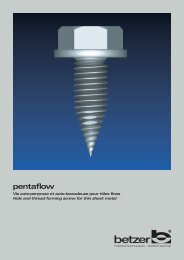
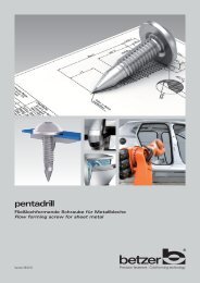
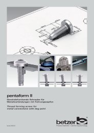
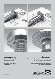
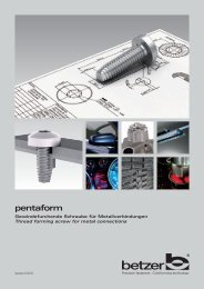
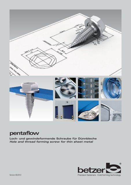
<strong>pentaflow</strong>Loch- und gewindeformende Schraube für DünnblecheHole and thread forming screw for thin sheet metalVersion 09/2012
<strong>pentaflow</strong><strong>pentaflow</strong> Form C<strong>pentaflow</strong> Form C2
<strong>pentaflow</strong>Eigenschaften Form Cmit spitzem SchaftendeFeatures of Form Cwith a conical pointEigenschaften Form Fmit abgeflachtem SchaftendeFeatures of Form Fwith truncated cone pointFür nicht gelochte, gekörnteoder vorgelochte Dünnbleche.Die Ausbildung des spitzenSchaftendes an der <strong>pentaflow</strong>Schraube bewirkt die schnelleLochformung.Spezielle Gewindeflanken imKegel bereich des <strong>Schrauben</strong> -schaftes formen den Blech -durchzug.For unstamped, grained orstamped thin sheet metal.The conical point of the<strong>pentaflow</strong> screw leads toquick hole forming.Special flanks of the thread inthe conical part of the shankform the rim of the hole.Für vorgelochte Bleche.Leichtes Finden und Positio -nieren durch kegelförmigesSchaftende.Schutz von empfindlichenBauteilen, z.B. Kabel durchabgeflachtes Schaftende.Verminderung der Verletzungsgefahrfür den Monteur.For stamped thin sheet metal.<strong>Co</strong>nical shank end for easyfinding and positioning.Truncated point for betterprotection of sensitivecomponents such as cables.Reduced risk of injury forthe operator.Der Fünfkant im Gewin de -furchbereich fördert die zentrischeGewinde ausformung.The pentagon in the thread formingportion assists the centricaltap formation.Ansonsten gleicheEigenschaften wie Form C.In all other respects identicalto Form C.Die <strong>pentaflow</strong> Schraube wirdeinsatzgehärtet und angelassen(„einsatzvergütet“) hergestelltund ist damit eine robusteSchrau be mit hoher Festigkeit.The <strong>pentaflow</strong> screw is casehardened and tempered,resulting in a very sturdy screwwith high tensile strength.Besonders gut geeignet für dieautomatische Montage.Suitable for automaticassembly.Anwendungsbeispiele: Automotive und HausgeräteindustrieApplications: automotive and appliance industries<strong>pentaflow</strong> Form F<strong>pentaflow</strong> Form F3
<strong>pentaflow</strong>EinschraubverhaltenAssembly processForm CEinschraubdrehmoment [Nm]Penetration torque [Nm]Form FDrehwinkel/GradTurning angle/degreesM E maxHandhabungsvorteileInstallation advantagesNur geringe manuelleAnpresskraft notwendig.Little manual contact pressurerequired.[Nm]6,0Lochformung beginnt bereitsnach wenigen <strong>Schrauben</strong>umdrehungen.The hole begins to form afterjust a few turns of the screw.3,0Je nach Blechstärke undWerkstofffestigkeit sindSchraubgeräte ab ca.1000 U/min einsetzbar.Depending on the thicknessand strength of the sheet it ispossible to use screw driversfrom approx. 1000 rpm.0,00 3000Drehmoment-Zeitverlauf für unten genannten AnwendungsfallTorque-curve vs. time in application shown below6000[ms]Schon mit handelsüblichenAkku-Schraubern verschraubbar(Abschalt-Drehmo ment-Einstellung empfohlen).Suitable also for commerciallyavailable battery driven screwdrivers(switch-off torqueoption recommended).AnwendungsfallSchraube:pfl M4x20 BN-30-14-115ApplicationScrew:pfl M4x20BN-30-14-115Wiederholtes Lösen undAnziehen der <strong>pentaflow</strong>Schraube möglich.The <strong>pentaflow</strong> screw can beremoved and retightenedrepeatedly.Material (ungelocht):Alublech 1,5 mm2 x Stahlblech 0,75 mmSheet material (unstamped):Aluminium 1.5 mm2 pcs. steel 0.75 mmWiederholungsverschraubungenmit <strong>Schrauben</strong> mitmetrischem Regelgewindemöglich.Subsequent screw fasteningwith standard metric screwspossible.Anpressdruck: 1000 NSchrauberdrehzahl: 300 U/minPressure: 1000 NDriver speed: 300 rpm5
<strong>pentaflow</strong><strong>Schrauben</strong>auslegung<strong>pentaflow</strong> Form CDetermination of <strong>pentaflow</strong>Form C design1. Bestimmung des empfohlenen <strong>Schrauben</strong>-Nenndurchmessers dBlechstärke s [mm]Empfohlener Nenndurchmesser d [mm]0,4 M 30,5 M 3 M40,6 M 3 M4 M50,8 (M 3) M4 M5 M61,0 M4 M5 M61,2 M5 M61,5 M6lb B 1sB 2d Ld2. Auswahl des empfohlenen Durchgangslochdurchmessers d L für das zu verschraubende BauteilNenndurchmesser d M 3 M 4 M 5 M 6empfohlene Durchgangslochdurchmesser d L [mm]4,1± 0,3 5,4 ± 0,4 7,0 ± 0,5 8,5 ± 0,53. Falls Vorlochung gewünscht: Bestimmung des empfohlenen Lochdurchmessers d B im DünnblechForm C:Für nicht gelochte, gekörnteoder vorgelochte DünnblecheForm C:For unstamped, grained orstamped thin sheet metalNenndurchmesser d M 3 M 4 M 5 M 6Blechstärke s [mm]empfohlener Lochdurchmesser d B [mm]0,4 0,8 (1,3) (1,3)0,5 1,1 1,6 (1,8) (2,3)0,6 1,4 1,8 1,9 (2,5)0,8 1,9 2,0 2,5 2,71,0 2,3 2,9 3,01,2 (2,6) 3,1 3,51,5 (3,4) 3,84. Bestimmung der maximalen Höhe des durch die Schraube geformten Blechdurchzugs B 2Nenndurchmesser d M 3 M 4 M 5 M 6Blechstärke s [mm]maximale Höhe des Blechdurchzuges B 2 [mm]0,4 1,2 (1,2) (1,2)0,5 1,5 1,5 (1,5) (1,5)0,6 1,8 1,8 1,8 (1,8)0,8 2,4 2,4 2,4 2,41,0 3,0 3,0 3,01,2 (3,6) 3,6 3,61,5 (4,5) 4,58betzer <strong>pentaflow</strong> <strong>Schrauben</strong> sind einsatzgehärtetund angelassen („einsatzvergütet“).Oberflächenbeschichtungen werden geliefertnach Wahl des Anwenders.Alle Angaben in den Tabellen sind empirischermittelt für Bleche aus dem Werkstoff St37(Zugfestigkeit ca. 370 N/mm 2 ), verzinkt.Für andere Werkstoffe und Festigkeiten könnendiese Angaben abweichen und müssen überanwendungsbezogene Versuche ermittelt werden.Weitere Gewindeaußendurchmesser auf Anfragebetzer <strong>pentaflow</strong> screws arecase hardened and tempered.Plating is supplied to users´ requirements.All information contained in the tables has beenempirically determined for sheets of material St37(tensile strength approx. 370 N/mm 2 ), galvanised.These values may be different for other materialsand strengths and should be determined byapplication tests.Other thread dimensions on request5. Bestimmung der mindestens benötigten Gewindelänge b b = B 1 + B 2+ =Bauteilhöhe B 1 maximale Höhe Blechdurchzug B 2 minimale Gewindelänge b6. Bestimmung der <strong>Schrauben</strong>schaftlänge lNenndurchmesser d M 3 M 4 M 5 M 6Schaftlänge l [mm] Toleranz [mm] mindestens benötigte Gewindelänge b [mm]8 ±0,3 210 ±0,3 412 ±0,3 6 414 ±0,3 8 6 416 ±0,3 10 8 6 518 ±0,4 12 10 8 620 ±0,4 14 12 10 825 ±0,4 19 17 15 1330 ±0,4 24 22 20 1835 ±0,5 27 25 2340 ±0,5 32 30 2845 ±0,5 35 3350 ±0,5 40 3855 ±0,6 Überlängen auf Anfrage 4360 ±0,6 48Version 09/2012
<strong>pentaflow</strong><strong>Schrauben</strong>auslegung<strong>pentaflow</strong> Form FDetermination of <strong>pentaflow</strong>Form F design1. Bestimmung des empfohlenen <strong>Schrauben</strong>-Nenndurchmessers dBlechstärke s [mm]Empfohlener Nenndurchmesser d [mm]0,4 M 30,5 M 3 M40,6 M 3 M4 M50,8 M 3 M4 M5 M61,0 M4 M5 M61,2 (M4) M5 M61,5 (M5) M62. Auswahl des empfohlenen Durchgangslochdurchmessers d L für das zu verschraubende BauteilNenndurchmesser d M 3 M 4 M 5 M 6lb B 1B 2sd Ld3. Bestimmung des notwendingen Lochdurchmessers d B im Dünnblechempfohlene Durchgangslochdurchmesser d L [mm]4,1± 0,3 5,4 ± 0,4 7,0 ± 0,5 8,5 ± 0,5Nenndurchmesser d M 3 M 4 M 5 M 6Blechstärke s [mm]empfohlener Lochdurchmesser d B [mm]Form F:Nur für vorgelochte0,4 1,7 (2,2) (2,7)0,5 1,7 2,2 (2,7) (3,2)0,6 1,8 2,2 2,7 (3,2)0,8 1,9 2,2 2,7 3,21,0 2,3 2,9 3,21,2 (2,6) 3,1 3,51,5 (3,4) 3,8Dünnbleche4. Bestimmung der maximalen Höhe des durch die Schraube geformten Blechdurchzugs B 2Form F:For stamped thin sheetmetal onlyNenndurchmesser d M 3 M 4 M 5 M 6Blechstärke s [mm]maximale Höhe des Blechdurchzuges B 2 [mm]0,4 1,2 (1,2) (1,2)0,5 1,5 1,5 (1,5) (1,5)0,6 1,8 1,8 1,8 (1,8)0,8 2,4 2,4 2,4 2,41,0 3,0 3,0 3,01,2 (3,6) 3,6 3,61,5 (4,5) 4,5betzer <strong>pentaflow</strong> <strong>Schrauben</strong> sind einsatzgehärtetund angelassen („einsatzvergütet“).Oberflächenbeschichtungen werden geliefertnach Wahl des Anwenders.Alle Angaben in den Tabellen sind empirischermittelt für Bleche aus dem Werkstoff St37(Zugfestigkeit ca. 370 N/mm 2 ), verzinkt.Für andere Werkstoffe und Festigkeiten könnendiese Angaben abweichen und müssen überanwendungsbezogene Versuche ermittelt werden.Weitere Gewindeaußendurchmesser auf Anfragebetzer <strong>pentaflow</strong> screws arecase hardened and tempered.Plating is supplied to users´requirements.All information contained in the tables has beenempirically determined for sheets of material St37(tensile strength approx. 370 N/mm 2 ), galvanised.These values may be different for other materialsand strengths and should be determined byapplication tests.Other thread dimensions on requestVersion 09/20125. Bestimmung der benötigten Gewindelänge b b = B 1 + B 2+ =Bauteilhöhe B 1 maximale Höhe Blechdurchzug B 2 minimale Gewindelänge b6. Bestimmung der <strong>Schrauben</strong>schaftlänge lNenndurchmesser d M 3 M 4 M 5 M 6Schaftlänge l [mm] Toleranz [mm] mindestens benötigte Gewindelänge b [mm]8 ±0,3 510 ±0,3 7 6 512 ±0,3 9 8 7 614 ±0,3 11 10 9 816 ±0,3 13 12 11 1018 ±0,4 15 14 13 1220 ±0,4 17 16 15 1425 ±0,4 22 21 20 1930 ±0,4 27 26 25 2435 ±0,5 31 30 2940 ±0,5 36 35 3445 ±0,5 40 3950 ±0,5 45 4455 ±0,6 Überlängen auf Anfrage 4960 ±0,6 549
<strong>pentaflow</strong>KopfformenHead shapesSonderkopfformen sind herstellbar. <strong>Schrauben</strong>sicherungen unter Kopf: betzer sperrzahn oder betzer ripptech möglich.Special head shapes are possible. Locking devices under the head: betzer sperrzahn (ratchets) or betzer ripptech (ribs).BN-30-11-… / BN-31-11-…Form C:BN-30-11-…Form F:BN-31-11-…Gewinde Thread d M3 M4 M5 M6Gewindeabstand a max. 0,5 0,7 0,8 1Kopfdurchmesser dk max. 5,5 8,4 9,3 11,3Kopfhöhe k max. 1,65 2,7 2,7 3,3Linsenhöhe f ~ 0,7 1 1,2 1,4Kopfradius rf ~ 6 9,5 9,5 12Radius r max. 0,8 1 1,3 1,5Kreuzschlitzgröße 1 2 2 3Form H Hilfsmaß m 3,4 5,2 5,4 7,3Eindringtiefe min. 1,8 2,7 2,9 3,5max. 2,2 3,2 3,4 4,0Form Z Hilfsmaß m 3,1 5 5,3 7,1Eindringtiefe min. 1,83 2,65 2,90 3,40max. 2,08 3,10 3,35 3,85BN-30-12-… / BN-31-12-…Form C:BN-30-12-…Form F:BN-31-12-…Gewinde Thread d M3 M4 M5 M6Gewindeabstand a max. 0,5 0,7 0,8 1Kopfdurchmesser dk max. 5,6 8 9,5 12Kopfhöhe k max. 2,4 3,1 3,7 4,6Kopfradius rf ~ 5 6,5 8 10Kreuzschlitzgröße 1 2 2 3Form H Hilfsmaß m 3 4,4 4,9 6,9Eindringtiefe min. 1,4 1,9 2,4 3,1max. 1,8 2,4 2,9 3,6Form Z Hilfsmaß m 2,8 4,3 4,7 6,7Eindringtiefe min. 1,50 1,89 2,29 3,03max. 1,75 2,34 2,74 3,46BN-30-13-… / BN-31-13-…Form C:BN-30-13-…Form F:BN-31-13-…Gewinde Thread d M3 M4 M5 M6Gewindeabstand a max. 0,5 0,7 0,8 1Kopfdurchmesser dk max. 7,5 10 11,5 14,5Kopfhöhe k max. 2,35 3,05 3,55 4,55Kopfradius rf ~ 3,8 5,8 6,6 8,2Scheibenhöhe c max. 0,8 1,1 1,35 1,8Kreuzschlitzgröße 1 2 2 3Form H Hilfsmaß m 3 4,6 5 7,1Eindringtiefe min. 1,35 1,8 2,26 3,0max. 1,8 2,46 2,87 3,66Form Z Hilfsmaß m 2,9 4,3 4,7 6,7Eindringtiefe min. 1,58 1,88 2,28 3,02max. 1,83 2,34 2,74 3,48BN-30-14-115 / BN-31-14-115Form C:BN-30-14-115Gewinde Thread d M3 M4 M5 M6Gewindeabstand a max. 0,5 0,7 0,8 1Kopfdurchmesser dk max. 7,5 9 10,5 12,5Kopfhöhe (gesamt) k max. 3 3,9 4,3 5Scheibenhöhe c max. 0,8 1 1,2 1,3Schlüsselweite Nennmaß s max. 5,5 7 8 10Eckmass e min. 5,95 7,59 8,71 10,95Form F:BN-31-14-11510Alle Maße in MillimeterAll dimensions in millimetersWeitere Gewindeaußendurchmesser auf AnfrageOther thread dimensions on requestBN-30-14-115GewindeartKopfformKraftangriffThread typeHead shapeRecessVersion 09/2012
<strong>pentaflow</strong>KopfformenHead shapesSonderkopfformen sind herstellbar. <strong>Schrauben</strong>sicherungen unter Kopf: betzer sperrzahn oder betzer ripptech möglich.Special head shapes are possible. Locking devices under the head: betzer sperrzahn (ratchets) or betzer ripptech (ribs).BN-30-11-112 / BN-31-11-112Form C:BN-30-11-112Form F:BN-31-11-112A A A A ABN-30-12-112 / BN-31-12-112Form C:BN-30-12-112Form F:BN-31-12-112BN-30-13-112 / BN-31-13-112Form C:BN-30-13-112Form F:BN-31-13-112AGewinde Thread d M3 M4 M5 M6Gewindeabstand a max. 0,5 0,7 0,8 1Kopfdurchmesser dk max. 5,5 8,4 9,3 11,3Kopfhöhe k max. 1,65 2,7 2,7 3,3Linsenhöhe f ~ 0,7 1 1,2 1,4Kopfradius rf ~ 6 9,5 9,5 12Radius r max. 0,8 1,0 1,3 1,5instar Größe I 10 I 20 I 25 I 30Hilfsmaß A 2,8 3,95 4,5 5,6Eindringtiefe min. 0,88 1,42 1,65 2,02max. 1,15 1,80 2,03 2,42Gewinde Thread d M3 M4 M5 M6Gewindeabstand a max. 0,5 0,7 0,8 1Kopfdurchmesser dk max. 5,6 8 9,5 12Kopfhöhe k max. 2,8 3,8 4,2 5,5Kopfradius rf ~ 5 6,5 8 10instar Größe I 10 I 20 I 25 I 30Hilfsmaß A 2,8 3,95 4,5 5,6Eindringtiefe min. 1,1 1,75 2,1 2,40max. 1,4 2,16 2,4 2,80Gewinde Thread d M3 M4 M5 M6Gewindeabstand a max. 0,5 0,7 0,8 1Kopfdurchmesser dk max. 7,5 10 11,5 14,5Kopfhöhe k max. 2,8 3,8 4,2 5,5 4,55Kopfradius rf ~ 3,8 5,8 6,6 8,2Scheibenhöhe c max. 0,8 1,1 1,35 1,8 1,8instar Größe I 10 I 20 I 25 I 30Hilfsmaß A 2,8 3,95 4,5 5,6Eindringtiefe min. 1,1 1,75 2,1 2,401,4 2,16 2,4 2,80BN-30-15-113 / BN-31-15-113Form C:BN-30-15-113dtdtGewinde Thread d M3 M4 M5 M6Gewindeabstand a max. 0,5 0,7 0,8 1Kopfdurchmesser dc max. 5,64 7,66 8,79 11,05Kopfhöhe (gesamt) k max. 3,5 4,5 5,5 6,5Scheibenhöhe c max. 1,2 1,3 1,7 1,8exstar Größe E 4 E 5 E 6 E 8Hilfsmaß dt 3,70 4,60 5,55 7,30Form F:BN-31-15-113Titelbilder/Anwendungen: istockphoto.comAlle Maße in MillimeterAll dimensions in millimetersVersion 09/2012Weitere Gewindeaußendurchmesser auf AnfrageOther thread dimensions on requestBN-30-14-115GewindeartKopfformKraftangriffThread typeHead shapeRecess11
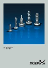
Präzision, die verbindetHerstellung großer Produktionsserienvon Präzisionsschraubenund Kaltformteilen nachZeichnungM1,6 – M12Drahtdurchmesser 1,0 – 11,8Produktlänge 2 mm – 120 mmGewindefurchende <strong>Schrauben</strong> fürKunststoffe, Metalle undLeichtmetalleDünnblechschraubenVerbindungselemente für dieautomatische MontagePrecision connectsManufacture of large series ofhigh-standard screws and coldformed partsM1.6 – M12Wire diameter 1.0 – 11.8Shank lengths 2 mm – 120 mmThread forming screws forplastics, metals andlight metalsScrews for thin sheet metalFasteners for automaticassembly119-092 · Layout & Produktion: Druckerei Vogel <strong>GmbH</strong> · www.druckerei-vogel.deDIN EN ISO 14001ISO/TS 16949DIN EN ISO 9001<strong>Schrauben</strong> <strong>Betzer</strong> <strong>GmbH</strong> & <strong>Co</strong>. <strong>KG</strong>Postfach 1243D-58462 LüdenscheidHeedfelder Straße 61-63D-58509 LüdenscheidTelefon: +49-(0)2351-9692-0Telefax: +49-(0)2351-9692-96mail@betzer.de · www.betzer.de