Akatherm-Plus dubbelwandig leidingsysteem - Glynwed A/S
Akatherm-Plus dubbelwandig leidingsysteem - Glynwed A/S
Akatherm-Plus dubbelwandig leidingsysteem - Glynwed A/S

Erfolgreiche ePaper selbst erstellen
Machen Sie aus Ihren PDF Publikationen ein blätterbares Flipbook mit unserer einzigartigen Google optimierten e-Paper Software.
InhoudsopgaveAlgemene informatie 1Buizen 26Fittingen 27Verbindingshulpstukken 45Sanitairaansluitingen 58Sifons 63Ontluchting 65Hemelwaterafvoer 67Laboratorium 68Halfschalen 69Isolatie 70Dubbelwandig 72ContentsGeneral information 7Pipes 26Fittings 27Connecting fittings 45Sanitary connections 58Siphons 63Ventilation 65Rainwater drainage 67Laboratory 68Support shells 69Insulation 70Dual containment 72InhaltsverzeichnisAllgemeine Information 13Rohre 26Fittings 27Verbindungsteile 45Sanitäranschlüsse 58Siphons 63Lüftung 65Dachentwässerung 67Labor 68Tragschalen 69Isolation 70Rohr-in-Rohr 72IndexInformation générale 19Tuyaux 26Raccords 27Piéces de raccordement 45Raccordements pour sanitaire 58Syphons 63Ventilation 65L’écoulement des eaux de pluie 67Laboratoire 68Chéneaux de support 69Isolation 70Tuyaux à double paroi 72
NLEigenschappen en voordelen PEEigenschappen PESlagvast en taaiVoordelenOnbreekbaar bijtemperaturen > 5 ºCBuigzaamMinimaal risico op breuken vervormingThermisch belastbaarToepassing mogelijktussen -40 ºC en 100 ºCInwendig gladde wandSlijtvastUV- en weerbestendigGeringer drukverlies dan bij anderematerialen. Kleine kans op verstoppingdoor geringe aanslag/residuwerkingLage kosten door relatief langelevensduur. Bestand tegen afvalwatermet daarin abrasieve vaste stoffenIn de buitenlucht onbeperkt inzetbaardoor inkleuring met roetChemisch resistentGeschikt voor transport vanverontreinigd afvalwaterIsolerendNiet elektrisch geleidendRecyclebaarMilieuvriendelijkIsolerendGeen condensatie gedurendekorte perioden van koelingUitstekend lasbaarEenvoudige verwerking d.m.v.stuiklas- en elektrolastechniekHomogene lasverbindingenTrekvast en lekdichtPrefabricageSnelle, kostenbesparende montageLicht in gewichtLage kosten transport en handling2
NLProductspecificatie<strong>Akatherm</strong> PE afvoer buizen en hulpstukken voldoen aan de gangbare internationale normenen beschikken over de volgende keurmerken:Land Keurmerk NormNederland NEN 7018NEN 7008België NBN EN 1519Duitsland DIN EN 1519DIN 19537Denemarken NKB Product Rules No. 8Zweden NKB Product Rules No. 8Frankrijk NF EN 1519Italië UNI EN 1519242Oostenrijk ÖNORM EN 1519Australië MP52 SPEC. 0053
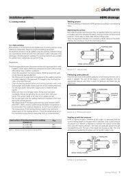
NLVerbindingstechniekenAlle in de tabellen weergegevenmaten van buizen en hulpstukken indeze catalogus zijn in mm, tenzijanders vermeld.Wanddikte<strong>Akatherm</strong> PE buizen en hulpstukken zijn geschikt vooréén of meerdere verbindingstechnieken. Hierbij dienteen onderscheid gemaakt te worden tussen nietdemonteerbareverbindingstechnieken (stuiklas-,elektrolas- en snapverbindingen) en demonteerbareverbindingstechnieken (steekverbindingen, schroefkoppelingenen flensverbindingen). Stuik- en elektrolassenworden samen met steekverbindingen hetmeest toegepast om PE leidingcomponenten onderlingte verbinden. Voor het aansluiten op sanitairetoestellen en andere leidingmaterialen worden o.a.steekverbindingen, krimpmoffen en klemverbindingentoegepast.Buizen en hulpstukkend 1 s 132 3,040 3,050 3,056 3,063 3,075 3,090 3,5110 4,3125 4,9160 6,2200 6,2250 7,8315 9,8Buizend 1 s 1110 3,5125 3,9160 5,04
NLStuiklassenStuiklassen is een zeer economische en betrouwbareverbindingstechniek, waarbij naast stuiklasapparatuurgeen additionele hulpstukken noodzakelijk zijn omdeze niet-demonteerbare lasverbinding tot stand tebrengen. Alle <strong>Akatherm</strong> buizen en hulpstukken zijnmet behulp van deze lasmethode te verbinden.Hulpstukken waarbij in de maattabellen een k-maat isopgenomen, kunnen maximaal met deze maat ingekortworden. Stuiklassen is zeer geschikt voor het prefabricerenvan leidingdelen en het maken van specialehulpstukken.ElektrolassenElektrolassen is een eenvoudige en snelle verbindingstechniekvoor het realiseren van niet-demonteerbarelasverbindingen. Met behulp van elektrolasmoffen eneen compact elektrolasapparaat is efficiënte montagevan buizen, hulpstukken en geprefabriceerde leidingenmogelijk.Het grootste gedeelte van het <strong>Akatherm</strong> assortiment isgeschikt voor elektrolassen.SteekverbindingenMet steekmoffen zijn zeer snel en eenvoudig demonteerbare,niet-trekvaste verbindingen te realiseren.Voor het realiseren van trekvaste steekverbindingenworden snapmoffen toegepast.5
<strong>Akatherm</strong>-<strong>Plus</strong> <strong>dubbelwandig</strong> <strong>leidingsysteem</strong>Het <strong>Akatherm</strong>-<strong>Plus</strong> <strong>dubbelwandig</strong> <strong>leidingsysteem</strong> is zeer geschikt voor het afvoeren van sterk vervuilde afvalwaterstromenop plaatsen waar extra zekerheid is vereist, zoals bij procesinstallaties, tankstations en wasinstallaties inwaterwingebieden.<strong>Akatherm</strong>-<strong>Plus</strong> leidingen bieden alle voordelen van een homogeen gelast <strong>leidingsysteem</strong>. Zowel de mediumvoerendebuis als de mantelbuis zijn namelijk in PE uitgevoerd. De buizen en <strong>dubbelwandig</strong>e hulpstukken kunnen eenvoudigmet elektrolasmoffen gemonteerd worden.NLTemperatuurbereikHet <strong>Akatherm</strong>-<strong>Plus</strong> systeem is inzetbaar tot een gemiddeldemediumtemperatuur van 60 °C. Door de vastepunten die standaard in de fittingen zijn ingebouwdwordt de binnenbuis gefixeerd in de mantelbuis.Afstandhouders centreren de binnenbuis in de mantelbuisen zorgen voor de noodzakelijke ondersteuning.tussenstukVerbindingsmethode A (diameters 110-160/125-200/160-250)tussenstukvast puntVerbindingsmethode B (diameter 200-315)LekdetectieVerbindingstechniekafstandhouderElektrolassen is de meest betrouwbare en economischeverbindingstechniek om hulpstukken en buis van het<strong>Akatherm</strong>-<strong>Plus</strong> programma met elkaar te verbinden.Afhankelijk van de diametercombinatie van binnenbuisen mantelbuis zijn er twee verbindingsmethoden.Bij verbindingsmethode A (diameters 110-160/125-200/160-250) wordt de binnenbuis met behulpvan één elektrolasmof gelast. Ook de mantelbuiswordt, na de tussenruimte door middel van het tussenstukgesloten te hebben, gelast met één elektrolasmof.Bij methode B (diameter 200-315) wordt de binnenbuisook met één elektrolasmof gelast, maar demantelbuis met twee elektrolasmoffen.Eventuele lekkages zijn eenvoudig vast te stellen doorgebruik te maken van de ruimte tussen binnenbuis enmantelbuis. Door een eindovergang toe te passen, inbijvoorbeeld een put, is het uitstromende lekkagewaterwaar te nemen. Hierdoor is het mogelijk bij inspectievast te stellen of er een lekkage in een bepaald leidingtrajectopgetreden is.Het <strong>Akatherm</strong>-<strong>Plus</strong> <strong>dubbelwandig</strong> <strong>leidingsysteem</strong> kanechter ook worden uitgebreid met een elektronischlekdetectie- en lokalisatiesysteem. Dit systeem bewaaktzelf continu de ruimte tussen binnenbuis enmantelbuis en signaleert onmiddellijk de plaats vaneen eventuele lekkage.AfmetingenIn deze catalogus zijn de diametercombinaties 110-160,125-200, 160-250 en 200-315 opgenomen. Anderediameter- en materiaalcombinaties zijn ook leverbaar.6
EGeneral information PE drainage pipe systems<strong>Akatherm</strong> PE drainage pipes have been used for more than 30 years in areas of application where the drainage systemhas to meet high standards of durability and reliability. These standards are met by combining the excellent materialproperties of PE with homogeneous welded joints.The range covers an extensive package of pipes and fittings in diameters from 32 to 400 mm for the followingapplications, amongst others:Waste water drainageTheir high impact resistance, wide temperaturerange and outstanding chemical resistance make<strong>Akatherm</strong> PE drainage pipes extremely suitablefor draining water in utilities constructions (e.g.in hospitals, hotels, school buildings, etc.). Aswell as pipes and fittings, the range for this areaof application includes a selection of fittings forconnecting sanitary units.Siphonic roof drainagePull tight jointing techniques combined with PE’s highimpact resistance make <strong>Akatherm</strong> PE drainagepipes extremely suitable for the siphonic roofdrainage.Siphonic roof drainage systems are used inbuildings with large roof spans, such aswarehouses, production facilities and hangars.For connecting on to roof outlets, the range includespull tight plug-in joints (snap sockets) and threadedpieces.SewageGood flexibility, high impact resistance, a widetemperature range and excellent UV-resistance make<strong>Akatherm</strong> PE drainage pipes extremely suitable for usein non pressure sewage systems. Non pressuresewage systems are used especially as groundpipework for the drainage of waste water andrainwater, and also for rainwater drainage fromroads and bridges.Dual containment drainage pipes are available aswell as the standard single-wall PE drainage range.This <strong>Akatherm</strong>-<strong>Plus</strong> system, which can be equippedwith leak detection equipment, offers the highestpossible security for the drainage of highly-pollutedwaste water.7
EProperties and benefits of PEPE propertiesBenefitsImpact-resistant and tough Unbreakable at temperatures > 5 °CElasticThermal resistantSuitable for undergroundpipes through adjustment tolocal ground movementApplication possible between-40 ºC and 100 ºCSmooth internal wallLow blockage risk due tolow deposit/residue effectsWear resistantLower costs due torelatively long lifeWeather-resistant/UV resistantChemical resistantApplication in open airunrestricted throughcolouring with carbon blackSuitable for transport ofpolluted waste waterInsulatingNon conductiveNon-toxicEnvironmental friendlyPoor heat conductivityNo condensation duringshort periods of coolingHighly suitable for weldingHomogeneous welded jointsEasy installation usingbutt welding andelectrofusion techniquesPull tight and leak proofPrefabricationFast and cost-saving installationLight in weightCost-saving in transportand handling8
EProduct specification<strong>Akatherm</strong> PE drainage pipes and fittings comply with current international standards and havethe following approvals:Country Certificate of approval StandardThe Netherlands NEN 7018NEN 7008Belgium NBN EN 1519Germany DIN EN 1519DIN 19537Denmark NKB Product Rules No. 8Sweden NKB Product Rules No. 8France NF EN 1519Italy UNI EN 1519242Austria ÖNORM EN 1519Australia MP52 SPEC. 0059
EJointing techniquesAll dimensions of pipes and fittingsshown in the tables are in mm,unless otherwise stated.WallthicknessOne or more jointing techniques may be used with<strong>Akatherm</strong> PE pipes and fittings. A distinction must bemade here between non-detachable jointing techniques(buttwelding, electrofusion and snap fittings)and detachable jointing techniques (plug-in joints,screw couplings and flanged joints). Butt welding andelectrofusion, together with plug-in joints, are themost commonly used ways of joining PE pipeworkcomponents together. Sanitary units and otherpipework materials are connected by using plug-injoints, retraction sockets and clamped joints.Pipes and fittingsd 1 s 132 3.040 3.050 3.056 3.063 3.075 3.090 3.5110 4.3125 4.9160 6.2200 6.2250 7.8315 9.8Pipesd 1 s 1110 3.5125 3.9160 5.010
EButtweldingButtwelding is a very economical and reliable jointingtechnique for making non-detachable welded joints,requiring only buttwelding equipment. All <strong>Akatherm</strong>pipes and fittings can be joined by this weldingmethod. Fittings for which a k-dimension is shown inthe table can be shortened by not more than thisamount. Buttwelding is extremely suitable for prefabricatingpipe sections and for making special fittings.ElectrofusionElectrofusion is a simple and rapid jointing techniquefor realising non-detachable welded joints.The efficient assembly of pipes, fittings and prefabricatedpipework can be achieved using electrofusioncouplers and compact welding equipment.The majority of the <strong>Akatherm</strong> range is suitable forelectrofusion.Plug-in jointsPlug-in sockets can be used to make very rapid andsimply-detachable non-pull-tight joints. Snap socketsare used to make pull-tight plug-in joints.11
<strong>Akatherm</strong>-<strong>Plus</strong> dual containment pipe systemThe <strong>Akatherm</strong>-<strong>Plus</strong> dual containment pipe system is extremely suitable for draining heavily-polluted waste water flowsin places where extra security is required, such as process installations, petrol stations and washing installations inwater extraction areas.<strong>Akatherm</strong>-<strong>Plus</strong> pipes offer all the benefits of a homogeneous welded pipe system. Both the inner pipe (carrying themedium) and the outer pipe are made from PE. The pipes and dual containment fittings can be simply joined withelectrofusion couplers.ETemperature rangeThe <strong>Akatherm</strong>-<strong>Plus</strong> system can be used with media atan average temperature of 60 °C. The inner pipe isattached in the outer pipe with fixed points that arestandard in the fittings. Spacers centre the inner pipein the outer pipe and provide the necessary support.adapterJointing method A (diameters 110-160/125-200/160-250)adapterfixed pointJointing method B (diameter 200-315)Leak detectionJointing techniquesspacerElectrofusion is the most reliable and economicaljoining technique for assembling pipes and fittings inthe <strong>Akatherm</strong>-<strong>Plus</strong> range. There are two methods ofjointing, depending on the combinations of diametersof the inner pipe and the outer pipe.In method A (diameters 110-160/125-200/160-250),the inner pipe is welded using a single electrofusioncoupler. The outer pipe is also welded using a singleelectrofusion coupler after the intermediate space hasbeen closed with the adapter.In method B (diameter 200-315), the inner pipe is alsowelded using a single electrofusion coupler, but theouter pipe is welded using two electrofusion couplers.Any leaks may be found easily by using the spacebetween the inner pipe and the outer pipe. By using anend adapter, for example in an inspection manhole,the water leaking out can be observed. It is possible toestablish in this way whether leaks have occurred in aparticular length of pipe.The <strong>Akatherm</strong>-<strong>Plus</strong> dual containment pipe system can beexpanded further with an electronic leak detection andlocalisation system. This system continuously monitorsthe space between the inner pipe and the outer pipeand indicates the position of any leak immediately.DimensionsThe diameter combinations 110-160, 125-200, 160-250en 200-315 are included in this catalogue. Othercombinations of materials and diameters are available.12
DAllgemeine Information über PE-Abflußleitungen<strong>Akatherm</strong>-PE-Abflußleitungen werden bereits seit 30 Jahren überall dort eingesetzt, wo an die Betriebssicherheit undZuverlässigkeit von Rohrleitungsanlagen große Anforderungen gestellt werden. Die hervorragenden Eigenschaftenvon Polyethylen, verbunden durch homogene Schweißverbindungen, macht es möglich, diese Anforderungen zuerfüllen. Das umfangreiche Sortiment enthält Rohre und Formstücke mit Durchmessern von 32 mm bis 400 mm fürdie folgenden Anwendungsgebiete:HausentwässerungDie hohe chemische Widerstandsfähigkeit, die hoheSchlagunempfindlichkeit, die hervorragendenhydraulischen Eigenschaften und der großeTemperatureinsatzbereich machen das <strong>Akatherm</strong>-PE-Abflußsystem besonders geeignet zurAbleitung von Schmutzwasser aus mehrgeschossigenWohngebäuden, Krankenhäusern, Hotels,Schulen usw. Neben Rohren und Fittings umfasst dasSortiment ein vollständiges PE-Formstückprogrammfür Apparateanschlüsse.Vakuum-DachentwässerungAufgrund der zugfesten Verbindungstechniken zusammenmit der hohen Schlagfestigkeit von PE eignensich <strong>Akatherm</strong>-Abwasserleitungen sehr gut zurUnterdruck-Ableitung von Regenwasser. DerartigeUnterdrucksysteme werden bei Gebäudenmit großen Dachflächen, wie z.B. Lagerhallen,Industriebauten, Hangars usw. angewendet. Fürden Anschluß an Dachabläufe enthält das Programmzugfeste Steckmuffen (Schnappmuffen) und Gewindemuffen.Grundstücksentwässerung und KanalleitungenAufgrund der hohen Elastizität, der hohen Schlagfestigkeitund des großen Temperaturbereichs eignensich <strong>Akatherm</strong>-PE-Abflußleitungen sehr gut für denBereich der erdverlegten Grundstücks- undEntwässerungskanalleitungen. Die hervorragendeUV-Beständigkeit der Rohre und Formstückeermöglicht auch den Einsatz im Bereich freiverlegter Brückenentwässerungsleitungen.Außer dem einwandigen PE-Standardprogrammsind auch doppelwandige Abflußleitungen lieferbar.Dieses <strong>Akatherm</strong>-<strong>Plus</strong>-System, auf Wunsch auch mitLeckage Warn- und Ortungsgeräten, bietet die höchstmöglicheBetriebssicherheit für die Ableitung starkverunreinigter Abwässer.13
DEigenschaften und Vorteile von PEEigenschaften PESchlagzähVorteileUnzerbrechlich bei Temperaturenüber 5 °CFlexibelMinimale BruchanfälligkeitThermisch belastbarAnwendung möglichzwischen -40 ºC und +100 ºCGlatte InnenoberflächenGeringe Neigungen zuVerstopfungen und AblagerungenVerschleißfestNiedrige Kosten durchlange LebensdauerGute UV-Licht- undWitterungsbeständigkeitUneingeschränkterEinsatz im FreienWiderstandsfähiggegen ChemikalienGeeignet für den Transportvon verunreinigten AbwässerIsolierendNicht elektrisch LeitfähigPhysiologisch unbedenklichUmweltfreundlichIsolierendSchweißbarHomogeneSchweißverbindungenKein Kondenzwasserbildungwährend kurzzeitigemDurchfluß von kalten MedienEinfache Verarbeitungdurch Stumpf- oderElektromuffenschweißungLängskraftschlüßig und dichtWerkseitige VorfertigungmöglichSchnelle, kostensparende MontageGeringes GewichtNiedrige Kosten fürTransport und Handling14
DProduktbeschreibung<strong>Akatherm</strong>-PE-Abflußrohre und Formstücke erfüllen alle gängigen internationalen Normenund besitzen die folgenden Prüfzeichen:Land Prüfzeichen NormNiederlande NEN 7018NEN 7008Belgien NBN EN 1519Deutschland DIN EN 1519DIN 19537Dänemark NKB Product Rules No. 8Schweden NKB Product Rules No. 8Frankreich NF EN 1519Italien UNI EN 1519242Österreich ÖNORM EN 1519Australien MP52 SPEC. 00515
DVerbindungstechnikenFalls nicht abweichend angegebensind alle Maße von Rohre undFormstücke in diesem Katalogin Millimetern aufgeführt.WandstärkeFür <strong>Akatherm</strong> PE-Abflußsysteme stehen mehrereVerbindungstechniken zur Verfügung. Hierbei wirdzwischen lösbaren (z.B. Steckmuffen, Flansch- undSchraubverbindungen) und unlösbaren Verbindungsarten(z.B. Heizelement-Stumpfschweißung undElektromuffen-Schweißung) unterschieden.Die Mehrzahl der Verbindungen von PE-Rohrleitungsteilenwerden ausgeführt durch HeizelementstumpfundElektroschweißverbindungen sowie mit Hilfe vonSteckmuffen. Zum Anschluß an sanitäre Anlagen undauf andere Materialien werden außerdem Steckverbindungen,Schrumpfmuffen und Klemmverbindungenverwendet.Rohre und Formstücked 1 s 132 3,040 3,050 3,056 3,063 3,075 3,090 3,5110 4,3125 4,9160 6,2200 6,2250 7,8315 9,8Rohred 1 s 1110 3,5125 3,9160 5,016
DHeizelement-StumpfschweißenDie Heizelement-Stumpfschweißung ist eine sehrwirtschaftliche und zuverlässige Verbindungstechnik.Zur Herstellung dieser unlösbaren Schweißverbindungbenötigt man ausschließlich ein entsprechendesSchweißgerät. Weitere zusätzliche Dichtelemente werdennicht benötigt. Alle <strong>Akatherm</strong>-Rohre und Formstückelassen sich mit dieser Schweißmethode verbinden.Formstücke, bei denen in den Maßtabellen ein k-Maßangegeben ist, können maximal auf dieses Maßgekürzt werden.Elektromuffen-SchweißungDie Elektromuffen-Schweißung ist eine einfache undschnelle Verbindungstechnik zur Herstellung unlösbarerSchweißverbindungen. Mit Hilfe von Elektroschweißmuffenund einem kompakten Elektroschweißgerätwird die Verbindung hergestellt. Der größte Teil des<strong>Akatherm</strong>-Sortiments ist für die Elektromuffen-Schweißung geeignet.SteckverbindungenMit Steckmuffen lassen sich schnell und einfach lösbareVerbindungen herstellen. Zur Herstellung unlösbarer,zugfester Steckverbindungen stehen <strong>Akatherm</strong>Steckmuffen mit Schnappring zur Verfügung.17
D<strong>Akatherm</strong>-<strong>Plus</strong> Rohr-in-Rohr SystemDas <strong>Akatherm</strong>-<strong>Plus</strong> Rohr-in-Rohr System eignet sich besonders zum Ableiten stark verschmutzter Abwässer an Orten,an denen eine große Betriebssicherheit verlangt wird, wie zum Beispiel in Prozeßanlagen, Tankstellen undWaschanlagen, die in Wasserschutzgebieten liegen.<strong>Akatherm</strong>-<strong>Plus</strong>-Leitungen haben alle Vorteile eines homogen geschweißten Rohrleitungssystems. Sowohl dasmediumführende Innenrohr als auch das Außenrohr sind aus PE hergestellt. Die Rohre und die doppelwandigenFormstücke lassen sich einfach mit Elektroschweißmuffen verbinden.TemperatureinsatzbereichDistanzstückDas <strong>Akatherm</strong>-<strong>Plus</strong>-System ist für Medientemperaturenbis max. 60 °C (erdverlegte Leitungen max. 45 °C)geeignet. Alle Formstücke sind standardmäßig mitFestpunkten versehen.Verbindungsvariante A (Durchmesser 110-160/125-200/160-250)DistanzstückFestpunktVerbindungsvariante B (Durchmesser 200-315)LecküberwachungVerbindungstechnikGleitkufeDie Verbindung mittels Elektromuffen ist für das<strong>Akatherm</strong>-<strong>Plus</strong>-System die zuverlässigste undwirtschaftlichste Verbindungstechnik, um Formstückeund Rohre miteinander zu verbinden. Je nach derDurchmesserkombination von Innen- und Außenrohrgibt es zwei Verbindungsvarianten.Bei der Variante A (Durchmesser 110-160/125-200/160-250) wird das Innenrohr mit Hilfe einer Elektroschweißmuffeverschweißt. Das Außenrohr wird, nachdemder Zwischenraum mit Hilfe eines Distanzstücksgeschlossen worden ist, mit einer weiteren Elektroschweißmuffeverschweißt.Bei der Variante B (Durchmesser 200-315) wird dasInnenrohr auch mit einer Elektroschweißmuffe, dasAußenrohr jedoch mit zwei Elektroschweißmuffenverschweißt.Eventuelle Undichtigkeiten lassen sich einfach durchdie Überwachung des Raumes zwischen dem InnenundAußenrohr feststellen. Durch die Verwendungeines Endübergangsstückes, beispielsweise in einemKontrollschacht, läßt sich prüfen, ob Leckwasser austritt.Auf diese Weise ist es möglich, während einerInspektion festzustellen, ob eine eventuelle Undichtigkeitin einem bestimmten Rohrleitungsabschnittentstanden ist.Das <strong>Akatherm</strong>-<strong>Plus</strong> Rohr-in-Rohr System kann allerdingsauch mit einer elektronischen Anlage zur Feststellungund Lokalisierung von Undichtigkeiten erweitert werden.Dabei wird der Hohlraum zwischen den Rohrenständig überwacht und der Ort einer auftretendenUndichtigkeit angezeigt.AbmessungenIn diesem Katalog sind die Durchmesserkombinationen110-160, 125-200, 160-250 und 200-315 enthalten.Andere Durchmesser- und Materialkombinationen sindebenfalls lieferbar.18
FInformations générales sur les tuyauteriesd’écoulement en PELes tuyauteries d’écoulement en PE <strong>Akatherm</strong> sont, depuis plus de 30 ans, utilisées dans des domaines d’applicationdans lesquels la durabilité et la fiabilité du système de canalisations doivent répondre à des exigences élevées.Les caractéristiques extraordinaires du PE et son aptitude à être combiné à des soudures homogènes permettent desatisfaire pleinement à ces exigences. L’assortiment comprend une gamme étendue de tuyaux et de raccords d’undiamètre de 32 à 400 mm à utiliser, entre autres, dans les applications suivantes :Ecoulement des eaux uséesDe par leur grande résistance aux chocs, leur plage detempérature étendue et leur extraordinaire stabilitéchimique, les tuyauteries d’écoulement en PE<strong>Akatherm</strong> sont idéales pour l’écoulement deseaux usées dans les bâtiments d’utilité publique(tels que les hôpitaux, hôtels, écoles, etc.). Pource type de domaine d’application, la gamme comprend,outre des tuyaux et des raccords, une gammeétendue d’accessoires de raccordement à des équipementssanitaires.Canalisation extérieureEcoulement des eaux de pluie par sous-pressionLa résistance à la traction des techniques de soudurecombinée à la résistance élevée aux chocs du PE fontdes tuyauteries d’écoulement <strong>Akatherm</strong> la solutionidéale pour l’écoulement par sous-pression des eauxde pluie.Les systèmes d’écoulement par sous-pression des eauxde pluie sont utilisés dans des bâtiments présentantune grande portée de toit, tels que desentrepôts, des ateliers, des hangars, etc. Pour leraccordement sur les crépines de toiture, lagamme comprend des raccords insérés(manchons à enclencher) résistants à la tractionet des pièces filetées.De par leur bonne flexibilité, leur résistance élevée auxchocs, leur plage de température étendue et leurexcellente stabilité aux UV, les tuyauteries d’écoulementen PE <strong>Akatherm</strong> sont particulièrement adaptéesaux canalisations extérieures sans pression. Lescanalisations extérieures sans pression sont surtoututilisées comme canalisations souterraines pourl’écoulement des eaux usées et des eaux de pluie,mais également pour l’écoulement des eaux de pluiedes chaussées et des ponts.La gamme d’écoulement en PE est disponible en versionstandard à paroi simple, mais également sous forme detuyauteries d’écoulement à double paroi. Le système<strong>Akatherm</strong>-<strong>Plus</strong>, qui peut éventuellement être équipéd’un dispositif de détection de fuites, offre une sécuritéoptimale en matière d’écoulement d’eaux uséesparticulièrement sales.19
FTechniques de raccordementSauf mention contraire, toutes lesdimensions de tuyaux et de raccordsfournies dans les tableaux de cecatalogue sont indiquées en mm.Epaisseur de paroiUne ou plusieurs techniques de soudure peuvent êtreutilisées sur les tuyaux et raccords en PE <strong>Akatherm</strong>. Ilfaut ainsi distinguer les techniques de raccordementnon-démontables (soudure bout à bout, électrosoudureet assemblage par enclenchement) et les techniques deraccordement démontables (raccords à emboîtement,raccords union et raccords à bride). La soudure bout àbout et l’électrosoudure sont le plus souvent utiliséesde manière combinée avec des raccords à emboîtementpour raccorder les composants des canalisationsen PE les uns aux autres. Le raccordement sur deséquipements sanitaires et autres matériaux de canalisationss’effectue, entre autres, par raccords àemboîtement, manchons à restreindre et raccords decompression.Tuyaux et raccordsd 1 s 132 3,040 3,050 3,056 3,063 3,075 3,090 3,5110 4,3125 4,9160 6,2200 6,2250 7,8315 9,8Tuyauxd 1 s 1110 3,5125 3,9160 5,022
FittingenFormstu« ckeFittingsRaccordsBocht 90³Bend 90³Bogen 90³Courbe 90³d 1 Art. Nr. I 1 r40 11 04 91 43 4050 11 05 91 53 5056 11 56 91 61 5663 11 06 91 66 6375 11 07 91 78 7590 11 09 91 93 90110 11 11 91 113 110125 11 12 91 135 125160 11 16 91 160 160200 11 20 91 205 200250 11 25 91 290 265315 11 31 91 340 300Bocht 90³ met lang beenBend 90³ with long sideBogen 90³ mit langem SchenkelCourbe 90³ a© bras longd 1 Art. Nr. I 1 I 2 r k 140 1104 92 93 43 40 4550 11 05 92 103 53 50 4556 11 56 92 120 59 56 5563 11 06 92 130 66 65 6075 11 07 92 140 78 75 6090 11 09 92 160 93 90 60110 11 11 92 180 113 110 60125 11 12 92 190 128 125 6030
FittingenFormstu« ckeFittingsRaccordsBocht 15³, 30³, 45³, 88,5³ verlengdBend 15³, 30³, 45³, 88,5³ extendedBogen 15³, 30³, 45³, 88,5³ verla« ngertCourbe 15³, 30³, 45³, 88,5³ a© bras longd 1 Art. Nr. l 1 r k 1110 15³ 18 11 15* 110 165 100125 15³ 18 12 15* 90 188 20160 15³ 18 16 15* 150 240 20200 15³ 18 20 15* 180 300 20250 15³ 18 25 15* 200 375 20315 15³ 18 31 15* 250 473 20110 30³ 18 11 30* 120 165 100125 30³ 18 12 30* 150 188 100160 30³ 18 16 30* 215 240 100200 30³ 18 20 30* 200 200 25250 30³ 18 25 30* 250 255 25315 30³ 18 31 30* 300 320 25160 45³ 11 16 45 160 160 100200 45³ 11 20 45 180 200 100250 45³ 11 25 45 205 255 100315 45³ 11 31 45 220 320 100160 88,5³ 11 16 88 250 160 100200 88,5³ 11 20 88 290 200 100250 88,5³ 11 25 88 350 325 100315 88,5³ 11 31 88 360 390 100* segmentgelast / segment welded / Segment geschweiÞt / soudë en segmentsVerloopbocht 90³Bend 90³ reducedBogen 90³ reduziertCourbe 90³ rëduitd 1 /d 2 Art. Nr. l 1 l 2 k 150/40 17 05 04 90 40 4063/50 17 06 05 119 50 5031
FittingenFormstu« ckeFittingsRaccordsBocht 180³Bend 180³Bogen 180³Courbe 180³d 1 Art. Nr. l 1 r32 11 03 99 32 3240 1104 99 40 4050 11 05 99 49 5056 11 56 99 49 4963 11 06 99 63 6475 11 07 99 75 7490 11 09 99 90 88110 11 11 99 103 99Bochten 180³ zijn geschikt voor het maken van sifons / Bends 180³ are suitable for the fabrication of siphonsBogen 180³ sind geeignet fu« r die Herstellung von Siphons / Courbe 180³ utilisables pour la fabrication des siphonsBocht 90³ kortBend 90³ shortBogen 90³ kurzCourbe 90³ courtd 1 Art. Nr. l 1 r40 11 04 90 39 4050 11 05 90 49 50Knie 88,5³Elbow 88,5³Winkel 88,5³Coude 88,5³d 1 Art. Nr. l 1 k 140 1204 88 55 2550 12 05 88 60 2056 12 56 88 65 2063 12 06 88 70 2075 12 07 88 75 2090 12 09 88 80 20110 12 11 88 95 25125 12 12 88 100 25160 12 16 88 120 2532
FittingenFormstu« ckeFittingsRaccordsKnie 45³Elbow 45³Winkel 45³Coude 45³d 1 Art. Nr. l 1 k 140 12 04 45 40 2050 12 05 45 45 2056 12 56 45 45 2063 12 06 45 50 2075 12 07 45 50 2090 12 09 45 55 20110 12 11 45 60 25125 12 12 45 65 25160 12 16 45 69 20Knie 45³ met lang beenElbow 45³ with long sideWinkel 45³ mit langem SchenkelCoude 45³ a© bras long¨d 1 Art. Nr. l 1 l 2 k 1 k 275 12 07 46 145 50 120 2590 12 09 46 150 55 120 25110 12 11 46 155 60 120 25125 12 12 46 155 65 120 25Kniee« n 45³ met lang been worden o.a. gebruikt voor de overgang vanstandleiding naar grondleiding conform DIN 1986 zie tekening)Elbows 45³ with long side are applied for making the bend from stack tobuilding drain acc. to DIN 1986 see drawing)Winkel 45³ mit langem Schenkel werden verwendet als Uë bergang vonFallleitung in Horizontalleitung gema« ss DIN 1986 siehe Zeichnung)Coudes 45³ a© bras long utilisës pour la transition de tuyaux de descenteaux tuyaux horizontaux suivant DIN 1986 voir dessin)33
FittingenFormstu« ckeFittingsRaccordsKnie 90³ met lang beenElbow 90³ with long sideWinkel 90³ mit langem SchenkelCoude 90³ a© bras longd 1 Art. Nr. l 1 l 2 r k 190 12 09 93 270 50 41 175110 12 11 93 300 60 40 220110 12 11 94 170 60 40 75^ Kniee« n 90³ met lang been zijn bedoeld voor toepassing in combinatie met wand- of vloerclosetmoffen art.nrs. 500951, 501171 en 50..01)^ Elbows 90³ with long side are applied in combination with wall or £oor lavatory sockets art.nos. 500951, 501171 and 50..01)^ Winkel 90³ mit langem Schenkel sind geeignet fu« r Anwendungen in Kombination mit Boden- oder Wand-WC-Muffen Art.Nr. 500951, 501171 und50..01)^ Coudes 90³ a© bras long utilisables en combinaison avec des manchons pour WC au sol ou suspendu art.nrs. 500951, 501171 et 50..01)34
FittingenFormstu« ckeFittingsRaccordsT-stuk 45³Branch 45³Abzweig 45³Të 45³d 1 /d 2 Art. Nr. l 0 l 1 /l 2 l 3 k 1 k 2 k 340/32 30 04 03 135 90 45 25 35 3040/40 30 04 04 135 90 45 30 30 2550/40 30 05 04 165 110 55 45 45 4050/50 30 05 05 165 110 55 20 20 3556/40 30 56 04 180 120 60 35 30 6056/50 30 56 05 180 120 60 30 30 4056/56 30 56 56 180 120 60 25 25 4063/40 30 06 04 195 130 65 40 45 4563/50 30 06 05 195 130 65 30 30 5063/56 30 06 56 195 130 65 25 25 4563/63 30 06 06 195 130 65 20 20 4075/40 30 07 04 210 140 70 60 50 6575/50 30 07 05 210 140 70 40 30 7075/56 30 07 56 210 140 70 35 25 5575/63 30 07 06 210 140 70 35 25 4575/75 30 07 07 210 140 70 25 25 4090/40 30 09 04 240 160 80 65 55 7590/50 30 09 05 240 160 80 50 40 8090/56 30 09 56 240 160 80 45 35 7590/63 30 09 06 240 160 80 40 30 7090/75 30 09 07 240 160 80 35 30 6590/90 30 09 09 240 160 80 20 20 50110/40 30 11 04 270 180 90 75 60 95110/50 30 11 05 270 180 90 55 50 95110/56 30 11 56 270 180 90 45 40 90110/63 30 11 06 270 180 90 40 35 85110/75 30 11 07 270 180 90 35 30 75110/90 30 11 09 270 180 90 30 25 65110/110 30 11 11 270 180 90 20 20 55125/50 30 12 05 300 200 100 115 60 75125/56 30 12 56 300 200 100 110 50 45125/63 30 12 06 300 200 100 60 45 105125/75 30 12 07 300 200 100 50 40 95125/90 30 12 09 300 200 100 35 30 30125/110 30 12 11 300 200 100 25 25 25125/125 30 12 12 300 200 100 20 20 2035
FittingenFormstu« ckeFittingsRaccordsT-stuk 45³Branch 45³Abzweig 45³Të 45³d 1 /d 2 Art. Nr. l 0 l 1 /l 2 l 3 k 1 k 2 k 3160/50 30 16 05* 375 250 125 120 115 65160/56 30 16 56* 375 250 125 120 115 65160/63 30 16 06* 375 250 125 120 115 65160/75 30 16 07* 375 250 125 120 115 65160/90 30 16 09* 375 250 125 110 105 55160/110 30 16 11 375 250 125 50 40 45160/125 30 16 12 375 250 125 10 20 40160/160 30 16 16 375 250 125 10 15 25200/75 30 20 07* 540 360 180 95 160 175200/90 30 20 09* 540 360 180 80 150 165200/110 30 20 11* 540 360 180 65 140 150200/125 30 20 12* 540 360 180 55 130 140200/160 30 20 16* 540 360 180 35 85 115200/200 30 20 20* 700 430 270 160 160 230250/110 30 25 11* 660 440 220 150 185 215250/125 30 25 12* 660 440 220 140 175 205250/160 30 25 16* 660 440 220 120 130 180250/200 30 25 20* 660 440 220 90 50 150250/250 30 25 25* 900 600 300 160 160 250315/110 30 31 11* 840 560 280 235 260 305315/125 30 31 12* 840 560 280 220 250 290315/160 30 31 16* 840 560 280 200 205 270315/200 30 31 20* 840 560 280 175 125 240315/250 30 31 25* 840 560 280 140 130 205315/315 30 31 31* 950 610 340 170 170 280* gelaste uitvoering / welded version / geschweiÞte Ausfu« hrung / version soudëe36
FittingenFormstu« ckeFittingsRaccordsT-stuk 88,5³Branch 88,5³Abzweig 88,5³Të 88,5³d 1 /d 2 Art. Nr. l 0 l 1 /l 2 l 3 k 1 k 2 k 340/40 20 04 04 130 55 75 25 25 4550/40 20 05 04 150 60 90 30 25 6050/50 20 05 05 150 60 90 25 25 5556/40 20 56 04 175 70 105 30 15 5556/50 20 56 05 175 70 105 35 30 7056/56 20 56 56 175 70 105 30 30 6563/40 20 06 04 175 70 105 30 30 7063/50 20 06 05 175 70 105 35 30 7063/56 20 06 56 175 70 105 30 30 6563/63 20 06 06 175 70 105 30 30 6075/40 20 07 04 175 70 105 40 25 7575/50 20 07 05 175 70 105 35 25 7075/56 20 07 56 175 70 105 30 25 6575/63 20 07 06 175 70 105 25 25 6075/75 20 07 07 175 70 105 25 25 5590/40 20 09 04 200 80 120 45 25 8590/50 20 09 05 200 80 120 45 25 8590/56 20 09 56 200 80 120 40 25 8590/63 20 09 06 200 80 120 35 25 8090/75 20 09 07 200 80 120 30 25 7590/90 20 09 09 200 80 120 25 25 70110/40 20 11 04 225 90 135 60 25 100110/50 20 11 05 225 90 135 50 25 95110/56 20 11 56 225 90 135 45 25 90110/63 20 11 06 225 90 135 40 25 90110/75 20 11 07 225 90 135 35 25 85110/90 20 11 09 225 90 135 30 25 75110/110 20 11 11 225 90 135 20 20 65125/50 20 12 05* 250 100 150 60 25 110125/56 20 12 56* 250 100 150 55 25 105125/63 20 12 06* 250 100 150 50 25 105125/75 20 12 07 250 100 150 45 25 100125/90 20 12 09 250 100 150 40 25 90125/110 20 12 11 250 100 150 30 20 80125/125 20 12 12 250 100 150 20 20 70* gelaste uitvoering / welded version / geschweiÞte Ausfu« hrung / version soudëe37
FittingenFormstu« ckeFittingsRaccordsT-stuk 88,5³Branch 88,5³Abzweig 88,5³Të 88,5³d 1 /d 2 Art. Nr. l 0 l 1 /l 2 l 3 k 1 k 2 k 3160/50 20 16 05* 350 140 210 75 30 145160/56 20 16 56* 350 140 210 75 30 145160/63 20 16 06* 350 140 210 65 30 140160/75 20 16 07* 350 140 210 80 45 150160/90 20 16 09* 350 140 210 55 30 125160/110 20 16 11 350 140 210 60 45 135160/125 20 16 12 350 140 210 50 45 125160/160 20 16 16 350 140 210 30 35 105200/75 20 20 07* 360 180 180 90 60 90200/90 20 20 09* 360 180 180 80 60 80200/110 20 20 11* 360 180 180 70 60 70200/125 20 20 12* 360 180 180 65 60 65200/160 20 20 16* 360 180 180 45 60 45200/200 20 20 20* 360 180 180 25 60 25250/110 20 25 11* 440 220 220 110 70 110250/125 20 25 12* 440 220 220 105 70 105250/160 20 25 16* 440 220 220 85 70 85250/200 20 25 20* 440 220 220 65 40 65250/250 20 25 25* 440 220 220 40 40 40315/110 20 31 11* 560 280 280 170 90 170315/125 20 31 12* 560 280 280 165 90 165315/160 20 31 16* 560 280 280 145 90 145315/200 20 31 20* 560 280 280 120 65 120315/250 20 31 25* 560 280 280 95 65 95315/315 20 31 31* 560 280 280 70 65 70* gelaste uitvoering / welded version / geschweiÞte Ausfu« hrung / version soudëe38
FittingenFormstu« ckeFittingsRaccordsDubbel T-stuk 45³Double branch 45³Doppelabzweig 45³Të double 45³d 1 /d 2 Art. Nr. l 1 l 2 l 3 k 1 k 2 k 340/40 36 04 04* 160 95 65 45 25 2550/40 36 05 04* 175 105 70 50 30 3050/50 36 05 05* 175 105 70 45 25 2556/40 36 56 04* 185 115 70 60 35 3056/50 36 56 05* 185 115 70 50 30 2556/56 36 56 56* 185 115 70 45 25 2563/40 36 06 04* 210 125 85 80 35 3063/50 36 06 05* 210 125 85 70 30 3063/56 36 06 56* 210 125 85 60 20 2063/63 36 06 06* 210 125 85 60 20 2075/40 36 07 04* 220 135 85 80 25 2075/50 36 07 05* 220 135 85 70 20 1075/56 36 07 56* 220 135 85 60 15 1075/63 36 07 06* 220 135 85 60 10 1075/75 36 07 07* 220 135 85 60 10 1090/40 36 09 04* 250 155 95 95 50 4090/50 36 09 05* 250 155 95 90 45 3590/56 36 09 56* 250 155 95 85 35 2090/63 36 09 06* 250 155 95 85 35 2590/75 36 09 07* 250 155 95 65 15 2090/90 36 09 09* 250 155 95 65 25 25110/40 36 11 04 270 180 100 110 65 45110/50 36 11 05 270 180 100 100 65 45110/56 36 11 56* 280 180 100 100 55 45110/63 36 11 06* 280 180 100 95 50 40110/75 36 11 07* 280 180 100 90 45 35110/90 36 11 09* 280 180 100 80 30 25110/110 36 11 11 270 180 100 65 20 20125/50 36 12 05* 300 220 80 115 75 55125/56 36 12 56* 300 220 80 115 75 55125/63 36 12 06* 300 220 80 115 90 75125/75 36 12 07* 300 220 80 90 60 45125/90 36 12 09* 300 220 80 80 50 30125/110 36 12 11* 300 220 80 70 45 40125/125 36 12 12* 300 220 80 60 35 35* gelaste uitvoering / welded version / geschweiÞte Ausfu« hrung / version soudëe39
FittingenFormstu« ckeFittingsRaccordsDubbel T-stuk 88,5³ gelastDouble branch 88,5³ weldedDoppelabzweig 88,5³ geschweiÞtTë double 88,5³ soudëd 1 /d 2 Art. Nr. l 0 l 1 /l 2 l 3 k 1 k 2 k 340/40 21 04 04 130 55 75 25 25 4550/40 21 05 04 150 60 90 30 25 6050/50 21 05 05 150 60 90 25 25 5556/40 21 56 04 175 70 105 30 15 5556/50 21 56 05 175 70 105 35 30 7056/56 21 56 56 175 70 105 30 30 6563/40 21 06 04 175 70 105 30 30 7063/50 21 06 05 175 70 105 35 30 7063/56 21 06 56 175 70 105 30 30 6563/63 21 06 06 175 70 105 30 30 6075/40 21 07 04 175 70 105 40 25 7575/50 21 07 05 175 70 105 35 25 7075/56 21 07 56 175 70 105 30 25 6575/63 21 07 06 175 70 105 25 25 6075/75 21 07 07 175 70 105 25 25 5590/40 21 09 04 200 80 120 45 25 8590/50 21 09 05 200 80 120 45 25 8590/56 21 09 56 200 80 120 40 25 8590/63 21 09 06 200 80 120 35 25 8090/75 21 09 07 200 80 120 30 25 7590/90 21 09 09 200 80 120 25 25 70110/40 21 11 04 225 90 135 60 25 100110/50 21 11 05 225 90 135 50 25 95110/56 21 11 56 225 90 135 45 25 90110/63 21 11 06 225 90 135 40 25 90110/75 21 11 07 225 90 135 35 25 85110/90 21 11 09 225 90 135 30 25 75110/110 21 11 11 225 90 135 20 20 65125/50 21 12 05 250 100 150 60 25 110125/56 21 12 56 250 100 150 55 25 105125/63 21 12 06 250 100 150 50 25 105125/75 21 12 07 250 100 150 45 25 100125/90 21 12 09 250 100 150 40 25 90125/110 21 12 11 250 100 150 30 20 80125/125 21 12 12 250 100 150 20 20 7040
FittingenFormstu« ckeFittingsRaccordsBroekstuk 60³Y-piece 60³Hosen-T-Stu« ck 60³Të culotte 60³d 1 /d 2 Art. Nr. l 1 l 2 k 1 k 250/40 37 05 04 55 110 40 5063/50 37 06 05 65 130 50 60110/110 37 11 11 90 10241
FittingenFormstu« ckeFittingsRaccordsOntstoppingsstuk 88,5³Clean out branch 88,5³Putzstu« ck 88,5³Të regard 88,5³d 1 /d 2 Art. Nr. D l 0 l 1 l 2 l 3 k 1 k 340/40 23 04 00 64 130 55 80 75 25 4550/50 23 05 00 72 150 60 72 90 25 5556/56 23 56 00 83 175 70 100 105 30 6563/63 23 06 00 87 175 70 100 105 30 6075/75 23 07 00 91 175 70 100 105 25 5590/90 23 09 00 118 200 80 100 120 25 70110/110 23 11 00 140 225 90 115 135 20 65125/110 23 12 00 140 250 150 120 150 20 80160/110 23 16 00 140 350 140 140 210 60 135200/110 23 20 00 140 360 180 160 180 90 90250/110 23 25 00 140 440 220 185 220 110 110315/110 23 31 00 140 560 280 220 280 170 170Ontstoppingsstuk 45³Clean out branch 45³Putzstu« ck 45³Të regard 45³d 1 /d 2 Art. Nr. D l 0 l 1 l 2 l 3 k 1 k 340/40 33 04 00 64 135 90 145 45 20 2050/50 33 05 00 72 165 110 142 55 20 3556/56 33 56 00 83 180 120 175 60 20 4063/63 33 06 00 87 195 130 166 65 20 4075/75 33 07 00 91 210 140 183 70 25 4090/90 33 09 00 118 240 160 199 80 20 50110/110 33 11 00 140 270 180 195 90 20 55125/110 33 12 00 140 300 200 200 100 25 25160/110 33 16 00 140 375 250 220 125 45 45^ Ontstoppingsstukken 45³ zijn bedoeld voor gebruik in horizontale en verticale leidingen^ Clean-out branches 45³ are applied in horizontal and vertical pipes^ Putzstu« cke 45³ werden angewendet in waagerechte und senkrechte Rohrleitungen^ Tës regards 45³ sont utilisës dans les tuyauteries horizontales et verticales42
FittingenFormstu« ckeFittingsRaccordsTweevoudig kogel-T-stuk 88,5³ gelastDouble ball branch 88,5³ weldedKugelabzweig 88,5³ geschweiÞtTë sphërique double 88,5³ soudëA B Cd 1 /d 2AArt. Nr.BArt. Nr.CArt. Nr. l 0 l 1 l 2 D k 1 k 2110/50 2411 142411 242411 34240 120 130 170 30 20110/56 2411 15 2411 25 2411 35 240 120 130 170 30 20110/63 2411 16 2411 26 2411 36 240 120 130 170 30 20110/75 2411 17 2411 27 2411 37 240 120 130 170 30 20110/90 2411 19 2411 29 2411 39 240 120 130 170 30 20110/110 2411 01 2411 02 2411 03 240 120 110 170 30 30125/50 2412 142412 242412 34260 130 145 190 30 20125/56 2412 15 2412 25 2412 35 260 130 145 190 30 20125/75 2412 17 2412 27 2412 37 260 130 145 190 30 20125/110 2412 01 2412 02 2412 03 260 130 125 190 30 40125/125 2412 12 2412 22 2412 32 260 130 125 190 30 40Meervoudig kogel-T-stuk 88,5³ gelastMultiple ball branch 88,5³ weldedMehrfachabzweig 88,5³ geschweiÞtTë sphërique multiple 88,5³ soudë A B Cd 1 /d 2AArt. Nr.BArt. Nr.CArt. Nr. l 0 l 1 l 2 D k 1 k 2110/50 3411 143411 24 411 14240 120 130 170 30 20110/56 3411 15 3411 25 4411 15 240 120 130 170 30 20110/75 3411 17 3411 27 4411 17 240 120 130 170 30 20110/90 3411 19 3411 29 4411 19 240 120 130 170 30 20110/110 3411 01 3411 02 4411 01 240 120 110 170 30 30125/50 3412 143412 24 412 14260 130 145 190 30 20125/56 3412 15 3412 25 4412 15 260 130 145 190 30 20125/75 3412 17 3412 27 4412 17 260 130 145 190 30 20125/110 3412 01 3412 02 4412 01 260 130 125 190 30 40125/125 3412 12 3412 22 4412 12 260 130 125 190 30 4043
FittingenFormstu« ckeFittingsRaccordsStromings-stuk 88,5³Branch 88,5³ swept entryBogenabzweig 88,5³Të coudë 88,5³d 1 /d 2 Art. Nr. l 0 l 1 l 2 k 1 k 2110/110 25 11 11 230 140 120 20 90Valleiding T-stukAeratorMischformstu« ckEmbranchement d'aërationAkaventd 1 Art. Nr. 1 / 2 / 3 4/ 5 / 6 l 0 l 1 l 2 l 3 l 4 l 5 l 6 l 7 l 8 l 9110 60 11 07 max. 1 110 mm max. 1 75 mm 750 320 170 260 275 90 180 55 130 90160 60 16 07 max. 1 110 mm max. 1 75 mm 715 320 160 235 310 100 200 75 125 110Het Akavent valleiding T-stuk wordt geleverd met dichte aansluitdeksels.Na het afzagen van de aansluitdeksels kunnen de gewensteaansluiteinden door stuiklas aangelast worden.The Akavent aerator will be delivered with closed caps. After removingthe caps, the required branches can be buttwelded to the aerator.Das Akavent Mischformstu« ck wird geliefert mit geschlossenenAnschluÞdeckeln. Nach Entfernung der Deckel ko« nnen die gewu« nschtenAnschlu« sse mittels StumpfschweiÞung hergestellt werden.L'embranchement d'aëration Akavent est livrë avec couvercles fermës.Apre© s l'enle© vement des couvercles, les branchements peuvent eª tre soudëspar bout a© bout.EindkapEnd capEndkappeBouchond 1 Art. Nr. l125 67 12 09 23160 67 16 09 25200 67 20 09 30250 67 25 09 30315 67 31 09 3044
VerbindingshulpstukkenVerbindungsteileConnecting ¢ttingsPie© ces de raccordementElektrolasmofElectrofusion couplerElektroschweiÞmuffeManchon ëlectrosoudabled 1 Art. Nr. D l 1 l 0 System40 41 04 95 52 22 54 5A/80s50 41 05 95 62 22 54 5A/80s56 41 56 95 68 22 54 5A/80s63 41 06 95 75 22 54 5A/80s75 41 07 95 87 22 54 5A/80s90 41 09 95 102 22 56 5A/80s110 41 11 95 122 22 58 5A/80s125 41 12 95 137 22 66 5A/80s160 41 16 95 172 22 66 5A/80s200 41 20 95 230 31 153 220V/420s250 41 25 95 285 31 153 220V/420s315 41 31 95 350 31 153 220V/420sDe elektrolasmoffen worden standaard geleverd met aanslagnokken.Deze nokken zijn eenvoudig te verwijderen met een mes, waardoor demof als overschuifmof gebruikt kan worden.Bij montage van de elektrolasmoffen, de buiseinden haaks afsnijden meteen buizensnijder, de oxidatielaag verwijderen met een schraper en deinsteekdiepte markeren.De moffen zijn eenvoudig te lassen met ons lasapparaat en anderedaarvoor geschikte apparaten.The electrofusion couplers are delivered with center stops. These stopscan easily be removed with a knife, so that the coupler can be used as aslide-on coupler.Before welding, cut pipe ends squarely with a pipe cutting tool, removethe oxide ¢lm with a scraper and mark the insertion depth. The couplerscan easily be welded with our control box and other suitable controlboxes.Die ElektroschweiÞmuffen werden standardma« Þig mit Mittenanschlaggeliefert. Dieser Mittenanschlag kann auf einfache Art mit ein Messerentfernt werden, damit die Muffe als Uë berschiebmuffe verwendetwerden kann. Vor der Montage mu« ssen die Rohrenden rechtwinkliggeschnitten werden, die Oxydschicht entfernt werden mit geeignetenWerkzeug Ziehklinge onder Abscha« lgera« t) und die Einstecktiefe derElektromuffe markiert werden.Die Muffen ko« nnen einfach mit unserem ElektroschweiÞgera« t oderanderen geeigneten ElektroschweiÞgera« te verschweiÞt werden.Les manchons ëlectrosoudables sont livrës standard avec des butëesd'arreª t. Ces butëes d'arreª t peuvent eª tre enlevë a© l'aide un couteau, desorte que les manchons peuvent eª tre utilisë comme manchon coulissant.Pour le montage des manchons, couper les tuyaux en ëquerre avec uncoupe-tubes, enlever la pellicule d'oxydation avec un racloir et marquerla profondeur d'embo|ªtement.Les machons peuvent eª tre soudes¨ avec notre appareil d'ëlectrosoudageet autres appareils d'ëlectrosoudage compatibles.45
VerbindingshulpstukkenVerbindungsteileConnecting ¢ttingsPie© ces de raccordement<strong>Akatherm</strong> CB315 electrolasapparaat & toebehoren<strong>Akatherm</strong> CB315 control box & accessories<strong>Akatherm</strong> CB315 ElektroschweiÞgera« t & Zubeho«r<strong>Akatherm</strong> CB315 appareil d'ëlectrosoudage & accessoiresd 1 Dim. V, Hz kg A max W max Art. Nr.40-315 270¾245¾175 230 50/60 4,3 10 2300 419800gele en blauwe aansluitkabels worden standaard met het lasapparaat Art.Nr. 419800 geleverdyellow and blue output leads are standard supplied with the control box Art.Nr. 419800gelber und blauer AnschluÞkabel werden standard mit dem SchweiÞgera« t Art.Nr. 419800 mitgeliefertles caª bles de soudages jaune et bleu sont inclus dans la livraison de l'appareil d'ëlectrosoudage Art.Nr. 419800Aansluitkabels / Output leads / AnschluÞkabel / Caª bles de soudaged 1 System Kleur Colour Farbe Coleur Art. Nr.40-160 5A/80s geel yellow gelb jaune 419851200-315 220V/420s blauw blue blau bleu 41985240-160 220V/60s groen green gru« n vert 419853200-315 220V/480s rood red rot rouge 419854Simultaanlassen / Welding simultaneously / SimultanschweiÞen / Soudures simultanëesd 1 System Kleur Colour Farbe Coleur Art. Nr. d1 6 200 5A/80s geel yellow gelb jaune 41985546
VerbindingshulpstukkenVerbindungsteileConnecting ¢ttingsPie© ces de raccordementSnap-expansiemof met speciedekselSnap expansion socket with protection plugSchnapp-Dehnungsmuffe mit SchutzstopfenManchon de dilatation a© enclencher avec bouchond 1 Art. Nr. D d l 0 l 132 40 03 20 50 33 172 13540 40 04 20* 58 41 172 13550 40 05 20* 68 51 172 13556 40 56 20* 74 57 172 13563 40 06 20 78 64 155 13575 40 07 20 90 76 155 13590 40 09 20 110 91 155 135110 40 11 20 130 111 155 135125 40 12 20 150 126 155 135160 40 16 20 186 162 165 135200 40 20 60* * 230 202 310 230250 40 25 60* * 300 253 330 250315 40 31 60* * 370 319 360 270* geschikt voor electrolas / suitable for electrofusiongeeignet fu« r ElektroschweiÞung / convient pour ëlectrofusion** zonder speciedeksel / without protection capohne Schutzkappe / sans bouchonDe snap-expansiemof kan als uitzettingsmof gebruiktworden. De aanwezigheid van de snapring naast derubber afdichtingsring) kan worden benut om deverbinding tussen buis en snap-expansiemof trekvastte maken. Voorwaarde is dat er in de buis een groefwordt gemaakt met een groevensnijder art.nr.41 92 04). De snap-expansiemoffen nemen delengteveranderingen van een buis met een lengte vanmax. 5 mtr. op. Een temperatuurverschil van 10³Cresulteert in een uitzetting of krimp van 8 mm. Deinsteekdieptes bij een omgevingstemperatuur van 0³Cen 20³C zijn aangegeven op de moffen 1 32-160 mm.The snap-expansion socket can be used as expansionsocket. The snap ring besides the rubber sealing ring)provides the possibility to make a tight-¢t connectionbetween pipe and snap socket, provided that a grooveis cut into the pipe with a groove cutter art.no.41 92 04).The snap-expansion sockets can absorb length changesof pipes with a max. length of 5 mtrs.A temperature difference of 10³C will result inexpansion or contraction of 8 mm. The insertion depthsat ambient temperature of 0³C and 20³C are indicatedon the sockets 1 32-160 mm.Die Schnappmuffe kann als Dehnungsmuffe benutztwerden. Die Schnappmuffen sind, neben demGummiring, mit einem Schnappring ausgestattetdamit eine kraftschlu« ssige Verbindung zwischen Rohrund Schnappmuffe hergestellt werden kann. Dazu sollmit eine Nutenfra« se Art.No. 41 92 04) eine Nut in dasRohrende eingedreht werden.Die Schnapp-Dehnungsmuffen ko« nnenLa« ngena« nderungen eines Rohrs von max. 5 Mtr.aufnehmen. Ein Temperatur-differenz von 10³C hateine Ausdehnung oder Kontraktion von 8 mm zurFolge. Die Einstecktiefen bei einer Umgebungstemperaturvon 0³C und 20³C sind auf die Muffe 132-160 mm markiert.Les manchons de dilatation sont fourni non seulementavec un joint en ëlastome© r mais ëgalement avec unebague d'enclenchement pour obtenir un raccord antiretractableentre le tuyau et le manchon. A cette ¢n ilest nëcessaire de couper une rainure a© l'extrëmitë dutuyau avec une coupe-rainure art.no. 41 92 04). Lesmanchons de dilatation peuvent absorber la variationde longueur des tuyaux de max. 5 mtr. Une variationde tempërature de 10³C engendre une dilatation ou uneretraction de 8 mm. Les profondeurs d'embo|ªtement a©la tempërature ambiante de 0³C en 20³C sont indiquëessur les manchons 1 32-160 mm.1 afdichtingsring / sealing ringGummiring / joint ëlastome© re2 snapring / snap ringSchnappring / bagued'enclenchement47
VerbindingshulpstukkenVerbindungsteileConnecting ¢ttingsPie© ces de raccordementSnapmof met speciedekselSnap socket with protection plugSchnappmuffe mit SchutzstopfenManchon a© enclencher avec bouchond 1 Art. Nr. D d l 0 l 140 4004 10 55 41 77 5550 400510 65 51 77 5563 400610 78 64 90 7075 400710 90 76 90 7090 400910 110 91 90 70110 40 11 10 130 111 90 70125 40 12 10 150 126 90 70160 40 16 10 190 162 130 105200 40 20 10 230 202 150 125De snapmof kan als steek- en trekvaste mof gebruiktworden. De aanwezigheid van de snapring naast derubber afdichtingsring) kan worden benut om deverbinding tussen buis en snapmof trekvast te maken.Voorwaarde is dat er in de buis een groef wordtgemaakt met een groevensnijder art.nr. 41 92 04).Het buisuiteinde dient bij montage geheel in desnapmof te worden geschoven.The snap socket can be used as a plug-in connectionand a tight-¢t connection. The snap ring besides therubber sealing ring) provides the possibility to make atight-¢t connection between pipe and snap socket,provided that a groove is cut into the pipe with agroove cutter art.no. 41 92 04).The pipe end schould be pushed into the snap socketentirely.Die Schnappmuffe kann als Steck- undMuffenverbindung benutzt werden. DieSchnappmuffen sind, neben dem Gummiring, miteinem Schnappring ausgestattet damit einekraftschlu« ssige Verbindung zwischen Rohr undSchnappmuffe hergestellt werden kann. Dazu soll miteiner Nutenfra« se Art.Nr. 41 92 04) eine Nut in dasRohrende eingedreht werden.Das Rohrende muÞ bei Montage vo« llig in dieSchnappmuffe eingeschoben werden.Les manchons a© enclencher sont utilisables commeraccord a© emboiter et rësistant a© la traction. Ils sontfournis avec un joint en ëlastome© re et bagued'enclenchement pour un raccordement antiretractableentre le manchon et le tuyau emboitë. Acette ¢n il est nëcessaire de couper une rainure a©l'extrëmitë du tube a© emboiter avec un coupe-rainureart.no. 41 92 04).Le tuyau s'emboite sur le manchon entie© rement aumontage.1 afdichtingsring / sealing ringGummiring / joint ëlastome© re2 snapring / snap ringSchnappring / bagued'enclenchement48
VerbindingshulpstukkenVerbindungsteileConnecting ¢ttingsPie© ces de raccordementSnapmof kort met speciedekselSnap socket short with protection plugSchnappmuffe kurz mit SchutzstopfenManchon court a© enclencher avec bouchond 1 Art. Nr. D d l 0 l 1110 40 11 40 130 111 55 45^ Korte snapmoffen kunnen als steek- en trekvaste moffen worden gebruikt en worden uitsluitend toegepast waar weinig inbouwruimte aanwezig isen lengteverandering niet kan worden opgevangen bijv. instortset standleiding)^ Short snapsockets can be used as a plug-in and a tight-¢t connection. They are applied at places where thermally caused length changes are notallowed f.e. imbedded stacks)^ Kurze Schnappmuffen ko« nnen als Steck- und kraftschlu« ssige Muffenverbindung benutzt werden u« berall dort wo wenig Einbauraum zur Verfu« gungsteht und wo thermische La« ngena« nderungen nicht aufgenommen werden ko« nnen z.B. einbetonnierte Fallleitung)^ Manchons courts a© enclencher utilisables comme raccord a© embo|ªter et anti-retractable sont d'utilitë lorsque l'on dispose de peu de place et qu'il estimpossible de rattraper la dilatation.Steekmof met speciedekselPlug-in socket with protection plugSteckmuffe mit SchutzstopfenManchon a© embo|ªter avec bouchond 1 Art. Nr. D d l 0 l 132 420350 48 33 57 4340 4204 50 53 41 75 5450 420550 67 51 75 5456 425650 72 57 80 5463 420650 84 64 95 6975 420750 96 76 95 6990 420950 110 91 95 69110 42 11 50 131 111 95 69Steekmof kort met speciedekselPlug-in socket short with protection plugSteckmuffe kurz mit SchutzstopfenManchon court a© embo|ªter avec bouchond 1 Art. Nr. D d l 0 l 150 420540 67 52 31 2575 420740 91 78 31 2549
VerbindingshulpstukkenVerbindungsteileConnecting ¢ttingsPie© ces de raccordementSchroefkoppeling kort compleet*Screw coupler short complete*Verschraubung kurz komplett*Raccord ¢letë court complet*d 1 Art. Nr. D l 0 l 1 l 2 l 340 43 04 00 60 50 38 25 3050 43 05 00 72 60 45 30 3256 43 56 00 83 60 45 30 3463 43 06 00 87 60 46 32 3575 43 07 00 103 65 51 36 4090 43 09 00 124 75 58 43 46110 43 11 00 144 90 72 48 56* draadstuk, wartel, drukring en gummidichting / threaded piece, nut, pressure ring and rubber ringGewindestutzen, Uë berwurfmutter, Schleifring und Gummidichtung / tubulure ¢letëe rond, ëcrou, bague de serrage et joint ëlastome© reSchroefkoppeling lang compleet*Screw coupler long complete*Verschraubung lang komplett*Raccord ¢letë long complet*d 1 Art. Nr. D l 0 l 1 l 2 l 340 4304 10 64 75 62 32 3350 430510 72 73 60 32 3256 435610 83 73 60 32 3463 430610 87 76 62 32 3575 430710 112 100 86 52 4590 430910 128 105 90 52 50110 43 11 10 145 105 90 52 65* draadstuk, wartel, drukring en gummidichting / threaded piece, nut, pressure ring and rubber ringGewindestutzen, Uë berwurfmutter, Schleifring und Gummidichtung / tubulure ¢letëe, ëcrou, bague de serrage et joint ëlastome© re50
VerbindingshulpstukkenVerbindungsteileConnecting ¢ttingsPie© ces de raccordementKraagbus voor schroefkoppelingCoupling collar for screw couplerBundbuchse zu VerschraubungCollerette pour raccordd 1 Art. Nr. D l 0 l 140 43 04 05 46 58 2750 43 05 05 57 66 3156 43 56 05 64 64 3063 43 06 05 70 73 3475 43 07 05 85 81 3890 43 09 05 100 101 48110 43 11 05 120 112 53Schroefkap kortScrew lock shortSchraubverschluÞ kurzRaccord ¢letë avec couvercle amovible courtd 1 Art. Nr. D l 0 l 1 l 2 l 340 67 04 00 60 50 38 25 3050 67 05 00 72 60 45 30 3256 67 56 00 83 60 45 30 3463 67 06 00 87 60 46 32 3575 67 07 00 103 65 51 36 4090 67 09 00 124 75 58 43 46110 67 11 00 144 90 72 48 56Schroefkap langScrew lock longSchraubverschluÞ langRaccord ¢letë avec couvercle amovible longd 1 Art. Nr. D l 0 l 1 l 2 l 340 67 04 10 64 75 62 32 3350 67 05 10 72 73 60 32 3256 67 56 10 83 73 60 32 3463 67 06 10 87 76 62 32 3575 67 07 10 112 100 86 52 4590 67 09 10 128 105 90 52 50110 67 11 10 145 105 90 52 6551
VerbindingshulpstukkenVerbindungsteileConnecting ¢ttingsPie© ces de raccordementDeksel voor schroefkap/eindkapLid for screw coupler/end capVerschluÞdeckel zu Verschraubung/EndkappeCouverde pour raccord/bouchon a© souderd 1 Art. Nr. D l 0 l 140 6704 07 46 15 1150 67 05 07 57 17 1356 67 56 07 64 17 1363 67 06 07 71 19 1575 67 07 07 85 22 1790 67 09 07 100 19 19110 67 11 07 120 20 20Ontstoppings-schroefkap kortInspection screw lock shortEndverschraubung kurzRegard courtd 1 Art. Nr. D l 075 66 07 00 91 4890 66 09 00 118 44110 66 11 00 140 50Ontstoppings-schroefkap langInspection screw lock longEndverschraubung langRegard longd 1 Art. Nr. D l 040 66 04 10 63 7350 66 05 10 73 7156 66 56 10 81 7463 66 06 10 89 7475 66 07 10 111 10690 66 09 10 128 106110 66 11 10 145 10652
VerbindingshulpstukkenVerbindungsteileConnecting ¢ttingsPie© ces de raccordementAansluitwartelScrew £ange with nutSchraubbo« rdel mit MutterTubulure de raccordementd 1 Art. Nr. R l 0 l 1 l 2 D32 98 03 81 1 1 440 98 04 82 1 1 250 98 05 83 200000035 21 21 5438 25 21 5944 30 21 72Schroefbus binnendraad kortFemale thread socket shortInnengewindemuffe kurzManchon ¢letë femelle courtd 1 Art. Nr. R l 0 l 1 D40 9104 793 440 9104 80 140 9104 81 1 1 450 91 05 80 150 91 05 81 1 1 450 91 05 82 1 1 263 91 06 82 1 1 263 91 06 83 2000000000000000038 30 4038 30 4538 30 5538 30 5038 30 5538 30 6338 30 6338 30 75Schroefbus binnendraad langFemale thread socket longInnengewindemuffe langManchon ¢letë femelle longd 1 Art. Nr. R l 0 l 1 D40 9204 793 440 9204 80 140 9204 81 1 1 450 92 05 80 150 92 05 81 1 1 450 92 05 82 1 1 263 92 06 82 1 1 263 92 06 83 275 92 07 84 2 1 200000000000000000070 30 4070 30 4570 30 5570 30 5070 30 5570 30 6370 30 6370 30 7570 30 9053
VerbindingshulpstukkenVerbindungsteileConnecting ¢ttingsPie© ces de raccordementPuntstuk buitendraad kortMale thread socket shortGewindestutzen kurzMamelon ¢letë maª le) courtd 1 Art. Nr. R I 040 96 04 781 240 96 04 793 440 96 04 80 140 96 04 81 1 1 450 96 05 80 150 96 05 81 1 1 450 96 05 82 1 1 263 96 06 82 1 1 263 96 06 83 2000000000000000000303030303535354040Puntstuk buitendraad langMale thread socket longGewindestutzen langMamelon ¢letë maª le) longd 1 Art. Nr. R I 040 9704 781 240 9704 793 440 9704 80 140 9704 81 1 1 450 97 05 80 150 97 05 81 1 1 450 97 05 82 1 1 263 97 06 82 1 1 263 97 06 83 275 97 07 84 2 1 2000000000000000000006060606065656570707054
VerbindingshulpstukkenVerbindungsteileConnecting ¢ttingsPie© ces de raccordementKrimpmof met dichtingRetraction socket with sealSchrumpfmuffe mit DichtungManchon thermorëtractable avec jointd 1 d Art. Nr. l 0 l 1 d x40 50 55 0405 160 60 3440 63 55 0406 180 90 34-4750 63 55 05 06 175 90 44-4750 75 55 05 07 195 90 44-5956 75 55 56 07 195 90 50-5963 75 55 06 07 190 90 57-5963 90 55 06 09 195 90 57-7475 90 55 07 09 190 90 69-7475 110 55 07 11 200 90 69-9490 110 55 09 11 190 90 83-9190 125 55 09 12 200 90 83-106110 125 55 11 12 195 90 101,4-104,4110 140 55 11 14 220 110 101,4-119,4125 140 55 12 14 215 110 115,4-118,4125 160 55 12 16 235 120 115,4-136,4160 180 55 16 18 245 120 147,6-153,6160 200 55 16 20 260 120 147,6-169,6200 225 55 20 22 265 120 187,6-194,6200 250 55 20 25 275 120 187,6-217,6250 315 55 25 31 450 150 234,4-279,4315 400 55 31 40 680 230 310,4-364,4d x = aansluitbereik / connecting range / AnschluÞbereich / mesures de connectionKrimpmoffen zijn bedoeld voor het eenvoudigaansluiten van PE op beton, gres, koper, rvs enz.zie tekening).1. De dichting over de aan te sluiten buis schuiven.2. De krimpmof over de buis met de dichtingschuiven en vervolgens met bijvoorbeeld hetelucht verwarmen.3. De mof krimpt en sluit aan over de buis.Retraction sockets are applied for jointing PE toconcrete, clayware, copper, stainless steel etc. seedrawing).1. Slip the seal over the pipe end.2. Then slide the retraction socket over the pipe endwith seal and heat it with for instance hot air.3. The socket will shrink and ¢tt over the pipe end.Schrumpfmuffen werden fu« r den AnschluÞ von PEzu Beton, Steinzeug, Kupfer, Edelstahl u.s.w. sieheZeichnung) angewendet.1. Den Dichtring auf den Stutzen stecken.2. Die Muffe u« ber den Stutzen mit Dichtringschieben und mit zum Beispiel HeiÞlufterwa« rmen.3. Durch Schrumpfung schlieÞt sich die Muffe u« berden Stutzen an.Manchons thermorëtractables sont utilisës pour leraccordement du PE vers bëton, gre© s, cuivre, acierinoxydable etc. voir dessin).1. Le joint ëlastome© re est en¢lë sur le tube a©raccorder.2. Le manchon est ensuite positionnë sur le tube avecle joint et chauffë par example a© l'air chaud.3. Le manchon se rëtrëcit et assure le raccordement.55
VerbindingshulpstukkenVerbindungsteileConnecting ¢ttingsPie© ces de raccordementVoorlaskraagStub£angeVorschweiÞbundColletd 1 Art. Nr. d 2 D l 0 l 1 k 140 47 04 02 50 78 50 10 1550 47 05 02 61 88 50 10 1556 47 56 02 70 102 60 14 1563 47 06 02 75 102 50 14 1575 47 07 02 89 120 50 16 1590 47 09 02 105 136 80 17 20110 47 11 02 125 158 80 18 30125 47 12 02 132 158 80 18 30160 47 16 02 175 210 80 18 30200 47 20 02 232 268 100 18 40250 47 25 02 285 320 100 20 40315 47 31 02 335 370 100 20 40Hypalon dichtingHypalon £at gasketHypalon FlachdichtungJoint plat hypalonDN d 1 Art. Nr. D di b32 40 4704 14 78 34 340 50 470514 88 44 350 56 475614 102 57 350 63 470614 102 57 365 75 470714 122 69 380 90 470914 138 83 3100 110 47 11 14 158 101 3125 125 47 12 14 158 115 3150 160 47 16 14 212 148 3200 200 47 20 14 268 188 3250 250 47 25 14 320 234 3300 315 47 31 14 370 295 356
VerbindingshulpstukkenVerbindungsteileConnecting ¢ttingsPie© ces de raccordementOverschuif£ens PP met stalen kernBacking ring PP with steel coreLos£ansch PP mit StahleinlageBride folle PP avec noyau en acierDN d 1 Art. Nr. D K* C b d* n* M32 40 47 04 08 140 100 51 16 18 4 M1640 50 47 05 08 150 110 62 16 18 4 M1650 56 47 06 08 165 125 78 19 18 4 M1650 63 47 06 08 165 125 78 19 18 4 M1665 75 47 07 08 185 145 92 19 18 4 M1680 90 47 09 08 200 160 108 21 18 8 M16100 110 47 11 08 220 180 128 22 18 8 M16100 125 47 12 08 220 180 135 22 18 8 M16150 160 47 16 08 285 240 178 27 22 8 M20200 200 47 20 08 340 295 235 28 22 8 M20250 250 47 25 08 406 350 288 31 22 12 M20300 315 47 31 08 460 400 338 34 22 12 M20n = aantal bouten / number of bolts / Anzahl Schrauben / nombre de boulonsM = draad / thread / Gewinde / ¢letage* DIN 2501 PN1057
SanitairaansluitingenSanita« ranschlu« sseSanitary connectionsRaccordements pour sanitaireWandclosetbocht 90³Wall-lavatory bend 90³Wand-WC-Bogen 90³Coude 90³ pour WCd 1 d Art. Nr. I 1 I 2 I 3 I 4 I 5 k 190 90 50 09 84 225 76 34 83 17 120110 90 50 11 85 225 76 34 95 17 120110 110 50 11 82 225 75 30 92 19 120110 110 50 11 83 300 75 30 92 19 195Dubbele wandclosetbocht 90³ verticaal)Wall-lavatory double bend 90³ vertical)Wand-WC-Doppelbogen 90³ senkrecht)Coude double 90³ pour WC a© connection verticaled 1 d Art. Nr. I 1 I 2 k 1110 90 50 09 34 225 275 80110 110 50 11 34 185 270 6058
SanitairaansluitingenSanita« ranschlu« sseSanitary connectionsRaccordements pour sanitaireDubbele wandclosetbocht 90³ horizontaal)Wall-lavatory double bend 90³ horizontal)Wand-WC-Doppelbogen 90³ waagerecht)Coude double 90³ pour WC a© connection horizontaled 1 d Art. Nr. I 1 I 2 I 3 k 1110 90 50 09 35 360 100 275 200110 110 50 11 35 360 100 270 200Wandclosetbocht 90³ horizontaal)Wall-lavatory bend 90³ horizontal)Wand-WC-Bogen 90³ waagerecht)Coude 90³ pour WC a©connection horizontaleaansluiting links / connection left / AnschluÞ links / raccordement gauched 1 d Art. Nr. I 1 I 2 I 3 k 190 90 50 09 32 300 100 75 140110 90 50 10 32 350 100 75 170110 110 50 11 32 350 100 75 170aansluiting rechts / connection right / AnschluÞ rechts / raccordement droitd 1 d Art. Nr. I 1 I 2 I 3 k 190 90 50 09 33 300 100 75 140110 90 50 10 33 350 100 75 170110 110 50 11 33 350 100 75 17059
SanitairaansluitingenSanita« ranschlu« sseSanitary connectionsRaccordements pour sanitaireWandclosetmofWall-lavatory socketWand-WC-MuffeManchon pour WC a© connection horizontaled 1 Art. Nr. d D I 0 I 190 50 09 51 90 113 50 38110 50 11 51 90 111 31 20110 50 11 71 110 130 45 28SpeciestopProtection plugBaustopfenBouchon de protectiond 1 Art. Nr. D D 1 D 2 I 0 I 190 430919 109 90 103 98 27,0110 43 11 19 130 105 119 98 23,5VloerclosetmofFloor-lavatory socketBoden-WC-MuffeManchon pour WC au sold 1 Art. Nr. d D I 0 I 190 50 09 01 120 129 85 55110 50 11 01 120 129 88 60Vloerclosetbocht 90³Floor-lavatory socket with bend 90³Boden-WC-Muffe mit Winkel 90³Coude 90³ pour WC au sold 1 Art. Nr. d D I 1 I 2 I 3 k 190 50 09 11 120 129 270 65 123 175110 50 11 11 120 129 300 60 140 21560
SanitairaansluitingenSanita« ranschlu« sseSanitary connectionsRaccordements pour sanitaireRubber dichting voor vloerclosetmof/-bochtRubber seal for £oor-lavatory socket/bendGummi Dichtung fu« r Boden-WC-Muffe/-WinkelJoint ëlastome© re pour manchon/coude pour WC au sold 1 Art. Nr. D d 2 I 0129 50 11 13 135 102 25d 2 = aansluitmaat / connecting size / AnschluÞmaÞ / dimension de connectionUrinoir aansluitmofUrinal connecting socketUrinal-AnschluÞmuffeManchon pour urinoird 1 Art. Nr. d I 0 I 1 D50 42 05 01 45 33 25 63Urinoir aansluitbochtUrinal connecting bendUrinal-AnschluÞwinkelCoude pour urinoird 1 Art. Nr. d I 1 I 2 I 3 k 1 D50 420511 45 147 55 25 100 63Sifonaansluitbocht 90³Siphon connecting bend 90³SiphonanschluÞwinkel 90³Coude raccordement 90³ pour syphond 1 Art. Nr. d D I 1 I 2 I 340 51 04 11 46 56 50 45 2050 51 05 11 46 53 45 45 1856 51 56 11 46 56 60 60 3050 51 05 12 58 65 50 45 2056 51 56 12 58 65 70 60 2863 51 06 12 58 65 60 55 2061
SanitairaansluitingenSanita« ranschlu« sseSanitary connectionsRaccordements pour sanitaireSifonaansluitbocht 90³*Siphon connecting bend 90³*SiphonanschluÞwinkel 90³*Coude raccordement syphon 90³*d 1 Art. Nr. d D I 1 I 2 I 3 I 4 k 150 52 05 11 46 60 90 62 20 16 5050 52 05 13 46 60 90 115 20 16 50* voor vastpuntmontage / for ¢xed point installation / fu« r Blockmontage / pour montage du point ¢xeSifonaansluitmofSiphon connecting socketSiphonanschluÞmuffeManchon raccordement syphond 1 Art. Nr. d D I 0 I 132 51 03 01 46 53 31 2340 51 04 01 46 53 30 2450 51 05 01 46 54 38 2756 51 56 01 46 53 38 2550 51 05 02 58 66 52 3956 51 56 02 58 64 46 32Rubber lippenring voor sifonmof/-bochtRubber nipple for siphon socket/bendGummi Lippenring fu« r SiphonanschluÞmuffe/-WinkelJoint ëlastome© re a© le© vre pour manchon/coude syphond 1 Art. Nr. d D I 0 I 14 6 51 33 01 1 1 /44 6 51 35 01 1 1 /258 51 35 02 1 1 /458 51 36 02 1 1 /258 51 37 02 2000000000032) 54 24 2040) 54 24 2032) 63 24 2040) 63 24 2050) 63 24 20Universele speciestop*Universal protection plug*Universal-Baustopfen*Bouchon de protection universel*Art. Nr.434619* voor alle sifonmoffen en -bochten / for all siphon sockets and siphon bendsfu« r alle SiphonanschluÞmuffen und -Winkel / pour tous manchons et coudes syphon62
SifonsSiphonsSiphonsSyphonsSifon inlaat/uitlaat verticaalSiphon inlet/outlet verticalSiphon Einlauf/Auslauf senkrechtSyphon entrëe/sortie verticaled 1 /d 2 Art. Nr. I 0 I 1 I 2 I 3 I 4 I 5 I 6 k 140/40 04 04 01 160 165 95 80 80 145 50 10050/40 04 05 01 170 175 100 90 80 155 50 10050/50 05 05 01 200 200 110 100 100 175 60 12556/50 05 56 01 200 225 135 100 100 200 60 15063/50 05 06 01 200 200 110 100 100 175 60 12556/56 56 56 01 210 220 130 110 100 195 60 13063/63 06 06 01 260 240 130 130 130 210 75 15075/75 07 07 01 300 275 130 150 150 240 85 175Sifon inlaat verticaal/uitlaat horizontaalSiphon inlet vertical/outlet horizontalSiphon Einlauf senkrecht/Auslauf waagerechtSyphon entrëe verticale/sortie horizontaled 1 /d 2 Art. Nr. I 0 I 1 I 2 I 3 I 4 I 5 k 140/40 04 04 02 172 92 145 95 80 50 4550/40 04 05 02 184 104 155 100 80 50 4550/50 05 05 02 204 104 180 115 100 60 4556/50 05 56 02 218 118 200 135 100 60 5563/50 05 06 02 218 118 185 120 100 60 5556/56 56 56 02 232 132 200 135 100 60 6063/63 06 06 02 262 132 210 130 130 75 60Sifon inlaat/uitlaat horizontaalSiphon inlet/outlet horizontalSiphon Einlauf/Auslauf waagerechtSyphon entrëe/sortie horizontaled 1 /d 2 Art. Nr. I 0 I 1 I 2 I 3 I 4 I 5 k 140/40 04 04 03 224 92 145 95 80 95 4550/40 04 05 03 236 104 155 100 80 100 4550/50 05 05 03 268 104 180 115 100 115 4556/50 05 56 03 282 118 200 135 100 135 5563/50 05 06 03 289 118 185 120 100 120 5556/56 56 56 03 296 132 200 135 100 135 6063/63 06 06 03 337 132 210 130 130 130 6063
SifonsSiphonsSiphonsSyphonsSifon universeel met kraagbusSiphon universal with coupling collarUniversal-Siphon mit BundbuchseSyphon universel avec colleretted 1 /d 2 Art. Nr. I 0 I 1 I 2 I 3 I 4 I 5 I 6 k 175 07 07 09 293 143 244 155 150 81 170 6090 09 09 09 445 270 250 150 175 101 203 175110 11 11 09 500 300 290 165 200 112 237 220inbouwmogelijkhedenpossibilities for applicationAnwendungsmo« glichkeitenpossibilitës d'applicationabcdgrotere diameters op aanvraag / larger diameters on requestgro« Þere Durchmesser auf Anfrage / diame© tres plus grands sur demandeBocht 180³ met schroefkoppelingen en kraagbussenBend 180³ with screw couplers and coupling collarsBogen 180³ mit Verschraubungen und Bundbu« chseCoude 180³ avec raccords ¢letës et collerettesd 1 Art. Nr. I 0 I 1 D40 04 04 04 130 110 8050 0405 04 155 130 10056 0456 04 158 130 10063 0406 04 182 150 13075 0407 04 208 170 15090 0409 04 248 203 175110 0411 04 292 237 200RioleringssifonSewer siphonKanalrohrsiphonSyphon d'ëgoutd 1 /d 2 Art. Nr. Type*90/90 09 09 01 1110/110 11 11 01 1125/110 12 11 01 2160/110 16 11 01 2200/110 20 11 01 2250/110 25 11 01 3315/110 31 11 01 3400/110 40 11 01 3* Type 1 = met T-stukken / with branches / mit Abzweige / avec embranchements* Type 2 = met bochten 90³ / with bends 90³ / mit Bogen 90³ / avec coudes 90³* Type 3 = met bochten 45³ / with bends 45³ / mit Bogen 45³ / avec coudes 45³64
OntluchtingLu« ftungVentilationVentilationVerluchtingskapRoof ventilation pipeDunstrohrCheminëe de ventilationd 1 Art. Nr. d 2 h40 6904 01 90 16550 69 05 01 90 16556 69 56 01 90 16563 69 06 01 90 17575 69 07 01 125 17590 69 09 01 125 175110 69 11 01 180 190125 69 12 01 200 190160 69 16 01 250 280Verluchtingskap voor vrije dakdoorgangRoof ventilation pipe for free roof passageDunstrohr fu« r freie DachdurchgangCheminëe de ventilation pour passage de toiture libred 1 Art. Nr. d 2 h40 6904 03 90 24550 69 05 03 90 24556 69 56 03 90 24563 69 06 03 90 25575 69 07 03 125 25590 69 09 03 125 255110 69 11 03 180 235125 69 12 03 200 235160 69 16 03 250 32565
OntluchtingLu« ftungVentilationVentilationAsfalteringsplaatAsphaltplateAsphalt-KlebeplattePlaque d'asphaltaged 1 Art. Nr. d 2 d 3 h40 69 04 05 50 330 30050 69 05 05 63 330 30056 69 56 05 75 330 30063 69 06 05 75 330 30075 69 07 05 90 330 30090 69 09 05 110 330 300110 69 11 05 125 330 300125 69 12 05 140 500 300160 69 16 05 180 500 300andere uitvoeringen op aanvraag leverbaar / other versions available on requestandere Ausfu« hrungen auf Anfrage lieferbar / autres versions livrables sur demandeVerluchtingskap met vaste asfalteringsplaatRoof ventilation pipe with ¢xed asphaltplateDunstrohr mit Asphalt-KlebeplatteCheminëe de ventilation avec plaque d'asphaltage ¢xed 1 Art. Nr. d 2 d 3 h40 69 04 04 90 330 30050 69 05 04 90 330 30056 69 56 04 90 330 30063 69 06 04 90 330 30075 69 07 04 125 330 30090 69 09 04 125 330 300110 69 11 04 180 330 300125 69 12 04 200 330 300160 69 16 04 250 500 350200 69 20 04 315 500 350250 69 25 04 400 600 350315 69 31 04 500 700 400400 69 40 04 620 700 400andere uitvoeringen op aanvraag leverbaar / other versions available on requestandere Ausfu« hrungen auf Anfrage lieferbar / autres versions livrables sur demande66
HemelwaterafvoerDachentwa« sserungRainwater drainageL'ëcoulement des eaux de pluieVergaarbak voor regenafvoer*Rainwater over£ow*Regenwassertrichter*Collecteur eau de pluie*d 1 Art. Nr. l b h75 07 00 10 250 200 20090 09 00 10 250 200 200110 11 00 10 250 200 200125 12 00 10 250 200 200160 16 00 10 350 250 250200 20 00 10 400 300 300*uit PE plaat 5 mm / from PE plate 5 mm / aus PE Platte 5 mm / plaque PE 5 mmandere uitvoeringen op aanvraag leverbaar / other versions available on requestandere Ausfu« hrungen auf Anfrage lieferbar / autres versions livrables sur demandeOnderdelen Components Einzelteile Accessoires Art. Nr.Spuwer Over£ow Uë berlauf Trop-plein 00 07 12Schuine zijden Bevelled sides Schra« ge Seiten Parois obliques 00 07 13Versterkte boordReinforcedborderRandversta«rkungBord derenforcement00 07 14Ophangstrook Fixing strip BefestigungsstreifenPlaque de¢xation00 07 1567
LaboratoriumLaborLaboratoryLaboratoireA£oopventiel kompleet PP)Outlet complete PP)Ablaufventil komplett PP)Bonde d'ëvacuation comple© te PP)Art. Nr.0410 10Onderdelen Components Einzelteile Accessoires Art. Nr.Draadstuk Thread piece Gewindeteil Pie© ce ¢letëe 0410 01Afstandsring Ring Zwischenring Rondelle 0410 02Pakking Seal Flachdichtung Joint 0410 03Moer Nut Mutter Ecrou 0410 04Zeef Sieve Ventilsieb Tamis 0410 11Wartel voor a£oopventielScrew £ange with nutAnschluÞverschraubungTubulure de raccordement ¢letë avec ëcrou mobileArt. Nr.98 05 00Afvoerplug PP)Outlet plug PP)Ventilstopfen PP)Bouchon PP)Art. Nr.0410 14Konus voor overlooppijp PP)Over£ow pipe conus PP)Standrohrkonus PP)Coª ne de tuyau de trop-plein PP)Art. Nr.0410 1268
HalfschalenTragschalenSupport shellsChëneaux de supportHalfschaal staal verzinktSupport shell steel galvanisedTragschale Stahl verzinktChëneau de support toª le galvanisëed 1 Art. Nr. s L32 90 03 00 0,63 300040 90 04 00 0,63 300050 90 05 00 0,63 300056 90 56 00 0,63 300063 90 06 00 0,63 300075 90 07 00 0,63 300090 90 09 00 0,63 3000110 90 11 00 0,63 3000125 90 12 00 0,63 3000160 90 16 00 0,63 3000200 90 20 00 0,63 3000250 90 25 00 0,63 3000315 90 31 00 0,63 300069
IsolatieIsolationInsulationIsolationAkoestische en thermische isolatieAcoustic and thermal insulationSchall- und Wa« rmeschutzIsolation acoustique et thermiqueAkasol1 vlamdovende kunststof folie / ¢re extinguishing plastic foilfeuerlo« schende Kunststoff-Folie / feuille matie© re synthëtique coupe feu2 lood / lead / Blei / plomb3 dubbel PUR-schuim / double PUR foam / doppel PUR-Schaum / mousse double-PUR4 sluitrail / guiding rail / VerschluÞschiene / glissie© rebuisvormig / tubular / rohrformig / tubulaired 1 Art. Nr. q mtr. / mtr. / Mtr. / mtr.)40 7804 00 1050 78 05 00 1056 78 56 00 1063 78 06 00 1075 78 07 00 1090 78 09 00 5110 78 11 00 5125 78 12 00 5160 78 16 00 5plaat / sheet / Platte / plaque* 78 35 00 1 st. / pc. / St. / pc.* afmeting 2 ¾ 1 mtr., bestaande uit folie / lood 0,5 mm / PUR-schuimdimension 2 ¾ 1 mtr., consisting of foil / lead 0,5 mm / PUR foamAbmessung 2 ¾ 1 Mtr., aus Folie / Blei 0,5 mm / PUR-Schaumdimension 2 ¾ 1 mtr., de feuille / plomb 0,5 mm / mousse-PURvoorgevormde kunststof folie voor afwerking van bochten 90³preformed plastic foil for ¢nishing bends 90³vorgefertigte kunststoff-Folie fu« r Verarbeitung von Bogen 90³feuille prëfabriquëe en matie© re synthëtique pour l'ache© vement des coudes 90³d 1 Art. Nr. q st. / pc. / St. / pc.)63 78 40 01 175 78 40 02 190 78 40 03 1110 78 40 04 1125 78 40 05 1160 78 40 06 1strip / strip / Streifen / bande* 78 37 00 1 mtr. / mtr. / Mtr. / mtr.* opvulmateriaal voor het isoleren van bochten, lengte 1 mtr. en breedte 20 mm, bestaande uit PUR-schuim / lood / PUR-schuim¢lling material for insulation of bends, length 1 mtr. and width 20 mm, consisting of PUR foam / lead / PUR foamFu« llmaterial fu« r das isolieren von Bogen, La« nge 1 Mtr. und Breite 20 mm, aus PUR-Schaum / Blei / PUR-Schaummatie© re de rembourrage pour isoler les coudes, longueur 1 mtr. et largeur 20 mm, de mousse-PUR / plomb / mousse-PURArt. Nr.tape / tape / Klebeband /ruban adhësif 78 36 00 1 st. / pc. / St. / pc.q = standaardverpakking / standard packing / Standard-Verpackung / emballage standardq70
IsolatieIsolationInsulationIsolationBenodigd materiaal in m 2 incl. reststukken / Material required in m 2 , scraps includedBeno« tigtes Material in m 2 , einschl. Verschnitt / Matëriel nëcessaire en m 2 ,dëchets inclusd 140 0,24 0,07 0,04 0,12 0,10 6850 0,26 0,08 0,04 0,13 0,11 7856 0,28 0,08 0,05 0,13 0,11 8463 0,30 0,09 0,05 0,14 0,12 9175 0,35 0,12 0,06 0,17 0,14 10390 0,38 0,17 0,07 0,21 0,17 118110 0,47 0,21 0,09 0,27 0,21 138125 0,50 0,25 0,11 0,32 0,25 153160 0,70 0,35 0,16 0,48 0,39 188MontageAkasol om de buis aanbrengen en bevestigen door middel van deschuifrail. Dwarsnaden afplakken met tape. Voor het verkrijgen van eenoptimale geluidsreductie dient te worden gelet op een goedenaadaansluiting. Met behulp van een industrieschaar laat het materiaalzich eenvoudig in de juiste vorm knippen.AssemblyPut Akasol on to the pipe and fasten it with the guiding rail. Cover thecross seams with tape. For a optimal noise reduction, the seams should beput together correctly. With an industrial scissor the material can beeasily cut into the correct form.MontageAkasol um dem Rohr anbringen und befestigen mit derVerschluÞschiene. Quernahte zukleben mit Klebeband. Fu« r eine optimaleSchallschutz soll man beachten, daÞ die Nahte gut anschliessen. Mit einerIndustrieschere la« Þt sich das Material einfach in der richtigen Formschneiden.MontageMonter l'Akasol autour du tuyau et fermer avec la glissie© re. Le joint destravers est a© fermer a© l'aide du ruban adhësif. A¢n d'obtenir unrendement maximum il est absolument nëcessaire de fermercorrectement les joints. A l'aide d'une paire de ciseaux industriellesl'Akasol peut eª tre aisement dëcoupë dans la forme dësirëe.71
DubbelwandigRohr-in-RohrDual containmentTuyaux a© double paroiKnie 45³Elbow 45³Winkel 45³Coude 45³d 1 d 2 Art. Nr. l 1 l 2 l 3160 110 121645-1145 295 35 150Knie 88,5³Elbow 88,5³Winkel 88,5³Coude 88,5³d 1 d 2 Art. Nr. l 1 l 2 l 3160 110 121688-1188 340 35 150Bocht 45³ r=d 1 )Bend 45³ r=d 1 )Bogen 45³ r=d 1 )Coude 45³ r=d 1 )d 1 d 2 Art. Nr. l 1 l 2200 125 112045-1245 365 35250 160 112545-1645 385 35315 200 113145-2045 440 75* FP = vast punt / ¢xed point / Festpunkt / point ¢xe72
DubbelwandigRohr-in-RohrDual containmentTuyaux a© double paroiDubbele bocht 2 ¾ 45³Double bend 2 ¾ 45³Umlenkung 2 ¾ 45³Coude double 2 ¾ 45³d 1 d 2 Art. Nr. l 1 l 2 l 3 l 4160 110 121647-1147 285 35 300 502200 125 122047-1247 365 35 300 577250 160 122547-1647 385 35 300 597315 200 123147-2047 440 75 300 652T-stuk 45³Branch 45³Abzweig 45³Të 45³d 1 d 2 d 3 d 4 Art. Nr. l 0 l 1 l 2 l 3 l 4 l 5 l 6160 160 110 110 301616-1111 615 545 440 475 35 35 440200 160 125 110 302016-1211 610 540 550 585 35 35 550200 200 125 125 302020-1212 770 700 670 705 35 35 670250 160 160 110 302516-1611 770 700 630 665 35 35 630250 200 160 125 302520-1612 770 700 680 715 35 35 680250 250 160 160 302525-1616 970 900 840 875 35 35 840315 160 200 110 303116-2011 1050 900 750 785 75 35 750315 200 200 125 303120-2012 1050 900 800 835 75 35 800315 250 200 160 303125-2016 1050 900 800 835 75 35 800315 315 200 200 303131-2020 1100 950 850 920 75 75 925* FP = vast punt / ¢xed point / Festpunkt / point ¢xe73
DubbelwandigRohr-in-RohrDual containmentTuyaux a© double paroiT-stuk 45³ met knie 45³Branch 45³ with elbow 45³Abzweig 45³ mit Winkel 45³Të 45³ avec courbe 45³d 1 d 2 d 3 d 4 Art. Nr. l 0 l 1 l 2 l 3 l 4 l 5 l 6 l 7160 160 110 110 311616-1111 615 545 250 285 35 35 220 440200 160 125 110 312016-1211 610 540 360 285 35 35 295 550200 200 125 125 312020-1212 770 700 430 365 35 35 355 670250 160 160 110 312516-1611 770 700 440 295 35 35 355 630250 200 160 125 312520-1612 770 700 440 365 35 35 360 680250 250 160 160 312525-1616 970 900 600 385 35 35 485 840315 160 200 110 313116-2011 1050 900 560 295 75 35 438 750315 200 200 125 313120-2012 1050 900 560 365 75 35 445 800315 250 200 160 313125-2016 1050 900 560 385 75 35 456 800315 315 200 200 313131-2020 1100 950 610 440 75 75 516 925* FP = vast punt / ¢xed point / Festpunkt / point ¢xeVerloopstuk concentrischReducer concentricReduktion konzentrischRëduction concentriqued 1 d 2 d 3 d 4 Art. Nr. l 0 l 1 l 2 l 3 l 4200 160 125 110 152016-1211 560 35 200 150 35250 160 160 110 152516-1611 580 35 200 150 35250 200 160 125 152520-1612 610 35 200 200 35315 160 200 110 153116-2011 720 75 200 150 35315 200 200 125 153120-2012 680 75 200 200 35315 250 200 160 153125-2016 660 75 200 200 3574
DubbelwandigRohr-in-RohrDual containmentTuyaux a© double paroiEind¢tting met schroefbus binnendraad 1 2End¢tting with female thread socket 1 2Endu« bergang mit Innengewindemuffen 1 2Passage d'extrëmitë avec manchon a© ¢letfemelle 1 200000000d 1 d 2 d 3 Art. Nr. l 0 l 1 l 2 l 3160 110 110 67 16 11 335 250 35 50200 125 125 67 20 12 340 260 35 50250 160 160 67 25 16 370 260 35 75315 200 200 67 31 20 435 260 75 100voor overgang van dubbel- naar enkelwandige buis / for connection from dual containment to singular pipefu« rUë bergang von Doppel- auf Einzelrohr / pour raccordement de tuyaux a© double paroi a© tuyaux simpleVloerputFloor drainEinlauftopfAvaloir de sold 1 d 2 d 3 d 4 Art. Nr. l 0 l 1 l 2 l 3verticaal / vertical / senkrecht / vertical 160 110 340 250 491611-0010 310 190 ^ 35horizontaal / horizontal / waagerecht / horizontal 160 110 340 250 491611-0020 330 190 315 35^ met uitneembare klokreukafsluiter, klemring en schroefbus binnendraad 1 2^ with removable bell trap, clamping ring and female thread socket 1 2^ mit a« uÞerem Schutztopf, Innengewindemuffe 1 2 , GeruchverschluÞglocke und Folienklemmring^ avec siphon a© cloche amovible, anneau de serrage et manchon ¢letë femelle 1 2uitvoering met zijdelingse inlaat op aanvraag / version with inlet on one side on requestAusfu« hrung met seitlichem Zulauf auf Anfrage / version avec raccordement de cotë sur demande0000000075
DubbelwandigRohr-in-RohrDual containmentTuyaux a© double paroiAfstandsringSpacerGleitkufePie© ce d'ëcartementDA DI Art. Nr. l h160 ¾ 6,2 110 ¾ 4,3 93 16 11 50 18200 ¾ 6,2 125 ¾ 4,9 93 20 12 130 25250 ¾ 7,8 160 ¾ 6,2 93 25 16 130 36315 ¾ 9,8 200 ¾ 6,2 93 31 20 130 36DA = diameter mantelbuis / diameter outer pipe / Durchmesser Aussenrohr / diame© tre tuyau externeDI = diameter binnenbuis / diameter inner pipe / Durchmesser Innenrohr / diame© tre tuyau interneTussenstuk voor buitenbuisConnecting piece for outer pipeDistanzstu« ck fu« r AussenrohrPie© ce de connection pour tuyau extërieurd 1 d 2 Art. Nr. l 0160 110 10 16 95 70200 125 10 20 95 70250 160 10 25 95 70315 200 10 31 95 150InspectieputManholeSchachtPuisard d'inspectiond 1Art. Nr.1000 6000021031200 600002103andere diameters en afmetingen op aanvraag / other diameters and dimensions on requestandere Duchmesser und Abmessungen auf Anfrage / autres diame© tres et dimensions sur demande76
For further information,please contact:<strong>Akatherm</strong> International B.V.Industrieterrein 11P.O. Box 7149NL-5980 AC PanningenThe NetherlandsTel.: +31 (0)77 3088650Fax: +31 (0)77 3075232E-mail: export@akatherm.nlWebsite: www.akatherm.comISO 9001 : 2000