1 - Tunnel
1 - Tunnel
1 - Tunnel

Sie wollen auch ein ePaper? Erhöhen Sie die Reichweite Ihrer Titel.
YUMPU macht aus Druck-PDFs automatisch weboptimierte ePaper, die Google liebt.
Offizielles Organ der STUVA · Official Journal of the STUVA<br />
www.tunnel-online.info<br />
3<br />
May<br />
2012<br />
Thailand: Long Term Flood Prevention in Chaophaya Basin<br />
Malaysia: Water <strong>Tunnel</strong> in Kuala Lumpur<br />
<strong>Tunnel</strong>ling: Influences on Segment Damage
h e r r e n k n e c h t A G | u t i l i t y t u n n e l l i n G | t r A f f i c t u n n e l l i n G s w i t z e r l A n d<br />
Biel: BreAkthrouGh for the lArGest tBM<br />
in switzerlAnd.<br />
B i e l | s w i t z e r l A n d<br />
PROJECT DATA CONTRACTOR<br />
S-452, EPB Shield Walo Bertschinger AG,<br />
Diameter: 12,560mm Porr Suisse AG,<br />
Installed power: 4,200kW Specogna Bau AG<br />
<strong>Tunnel</strong> length: 7,112m<br />
Geology: Molasse,<br />
unconsolidated material<br />
Herrenknecht AG<br />
D-77963 Schwanau<br />
Phone +497824302-0<br />
Fax +4978243403<br />
marketing@herrenknecht.com<br />
www.herrenknecht.com<br />
In the Swiss Canton of Bern, a new bypass of highway 5 is planned to relieve the city of Biel<br />
and the surrounding villages from the volume of traffic. The eastern branch of the two times<br />
five kilometers of highway includes the two double-tube tunnels of Büttenberg and Längholz.<br />
A Herrenknecht EPB Shield – with a diameter of 12,560 millimeters, the largest tunnel<br />
boring machine ever used in Switzerland – excavated the four tunnel tubes. Team and machine<br />
were congratulated enthusiastically at the breakthrough on February 18, 2012.<br />
The machine called “Belena” drove a total of 4.8km through hard rock and 2.3km through<br />
unconsolidated rock for the four tunnel tubes. In particular, tunnelling in the EPB mode through<br />
unconsolidated rock with overburdens of only 7 meters at some parts required enormous<br />
technical know-how from the tunnelling experts of the consortium “Arge <strong>Tunnel</strong>s Umfahrung<br />
Biel (ATUBO)”. Since team and technology were able to adapt increasingly to the onsite conditions,<br />
the second tubes of the two tunnels required a third less time, saving six weeks of<br />
time in completing their target. This is tunnel construction at highway speed with the Herrenknecht<br />
EPB Shield, which was able to operate in open and, if needed, also in closed mode<br />
when an unstable tunnel face had to be supported safely with compressed air.
<strong>Tunnel</strong> 3/2012<br />
Offizielles Organ der<br />
www.stuva.de<br />
Title<br />
Die Herrenknecht AG liefert insgesamt 6 EPB-<br />
Schilde sowie 2 Mixschilde für das europäische<br />
Megaprojekt Crossrail.<br />
Herrenknecht AG is delivering a total of 6 EPB<br />
Shields as well as 2 Mixshields for the European<br />
megaproject Crossrail.<br />
(Photo: Herrenknecht AG, Schwanau/D)<br />
Inhalt Contents<br />
1<br />
3/12<br />
The article on pp. 18 shows, what ITA-COSUF<br />
– the ITA Committee on Operational Safety of<br />
Underground Facilities – means.<br />
Aktuelles / Topical News 2<br />
Hauptbeiträge / Main Articles<br />
Long Term Flood Prevention in Chaophaya Basin, Thailand 16<br />
Thailand Underground and <strong>Tunnel</strong>ling Group<br />
ITA-COSUF: The Operation of Safe and Secure Underground Facilities 18<br />
G. Vollmann, R. Leucker, D.K. Sprakel<br />
Wasserversorgungstunnel in Kuala Lumpur 22<br />
Water <strong>Tunnel</strong> in Kuala Lumpur<br />
Desiree Willis<br />
Einflüsse auf Tübbingschäden 33<br />
Influences on Segment Damage<br />
T. Babendererde, Ch. Hahn<br />
Beobachtungsmethode in der Geotechnik –<br />
Verknüpfung von Messung und Simulation 40<br />
Observation Method in Geotechnics –<br />
Interlinking Measurements and Simulation<br />
F. Nagel, I. Spohr, L. Speier<br />
Umfahrung Lungern:<br />
Spritzbetonapplikation auf Kunststoffdichtungsbahn 48<br />
Lungern Bypass:<br />
Sprayed Concrete Application directly onto Polymer Waterproofing<br />
Membranes<br />
M. Jahn<br />
STUVA-Nachrichten / STUVA News 56<br />
Baumaschinen / Construction Equipment<br />
Besseres Nutzlastverhältnis, reinere Luft und höhere Produktivität 62<br />
Higher Payload Ratio, Cleaner Air and Enhanced Productivity<br />
Informationen / Information<br />
Veranstaltungen 61<br />
Events<br />
Inserentenverzeichnis 64<br />
Advertising list<br />
Impressum 64<br />
Imprint
2 Nachrichten<br />
News <strong>Tunnel</strong> 3/2012<br />
Großbritannien<br />
Die beiden ersten Crossrail-TBM<br />
beim Vortrieb<br />
Beim Projekt Crossrail soll eine<br />
neue Eisenbahnstrecke (rd. 20<br />
km) unter der Londoner Innenstadt<br />
mit jeweils 2 eingleisigen<br />
<strong>Tunnel</strong>röhren von rd. 7<br />
m Durchmesser mit insgesamt<br />
8 <strong>Tunnel</strong>vortriebsmaschinen<br />
gebaut werden. Die Arbeiten<br />
sind in mehrere Bauabschnitte<br />
unterteilt.<br />
Das 6,4 km lange Baulos<br />
C300 zwischen Royal Oak und<br />
Farringdon wird die Arbeitsgemeinschaft<br />
aus den Unternehmen<br />
BAM Nutall (mit Wayss &<br />
Freytag Ingenieurbau AG), Ferrovial<br />
Agroman und Kier Construction<br />
(BFK) ausführen – bei<br />
einem Auftragsvolumen von rd.<br />
500 Mio. GBP (600 Mio. EUR).<br />
Der erste EPB-Schild (S-705<br />
Herrenknecht AG) startete Mitte<br />
April 2012 vom Schacht nahe<br />
dem Royal Oak Portal aus in der<br />
Weströhre in Richtung nach<br />
Farringdon. Nach Montage des<br />
zweiten EPB-Schild (S-706 Herrenknecht<br />
AG) wird mit den Vortriebsarbeiten<br />
Ende Mai auch in<br />
der Oströhre begonnen werden.<br />
Die Tübbingproduktion in einer<br />
eigenen Feldfabrik am Old Oak<br />
Common wurde bereits im Februar<br />
2012 begonnen.<br />
Im Laufe dieses Jahres<br />
werden 2 weitere EPB-Schilde<br />
von Limmo im Docklands aus<br />
den 8,3 km langen Vortrieb<br />
in Richtung Farringdon über<br />
Whitechapel und Liverpool<br />
Street starten (Baulos C305)<br />
und im Winter dann 2 weitere<br />
<strong>Tunnel</strong>bohrmaschinen die 2,65<br />
km langen Vortrieb in Plumsted<br />
und unter der Themse aufnehmen<br />
(Baulos C310)<br />
Nach Abschluss der Arbeiten<br />
werden bis zu 24 Züge je Stunde<br />
und Richtung die <strong>Tunnel</strong>strecke<br />
in London durchfahren, was zu<br />
einer deutlichen Entlastung der<br />
Metrolinie Central und Piccadilly<br />
führen wird. Man rechnet mit<br />
jährlich rd. 200 Mio. Fahrgästen.<br />
Die Fahrzeiten aus dem Westen<br />
werden deutlich kürzer werden,<br />
so vom West End Londons bis<br />
zum Flughafen Heathrow nur<br />
noch 30 Minuten. G.B.<br />
Schweiz<br />
Galgenbucktunnel: Umgestaltung<br />
A4-Anschluss Schaffhausen Süd<br />
Mit der Umgestaltung des Anschlusses<br />
Schaffhausen Süd soll<br />
die Autobahn A4 an das örtliche<br />
Straßennetz angeschlossen<br />
werden. Kernstück dieser<br />
Baumaßnahme ist der 1.138 m<br />
lange Galgenbucktunnel zwischen<br />
Engi und Bahntal mit 2<br />
Fahrspuren im Gegenverkehr<br />
und 4,5 % Gefälle in Richtung<br />
Bahntal; er unterquert die Ge-<br />
meinde Neuhausen am Rheinfall<br />
in einem Bogen mit rd. 500<br />
m Halbmesser und im Bereich<br />
Bahntal den Charlottenfelstunnel<br />
der Deutschen Bundesbahn<br />
(DB) mit 5,50 m Abstand.<br />
Der <strong>Tunnel</strong> wird im Bereich<br />
der Portale im Tagbau erstellt<br />
und dazwischen 1.060 m von<br />
Egi fallend im Sprengvortrieb<br />
ausgebrochen (Kalottenaus-<br />
United Kingdom<br />
The 2 first Crossrail TBMs<br />
in Action<br />
For the Crossrail project a new<br />
rail link (approx. 30 km) is to be<br />
driven beneath central London<br />
involving 2 single-track tunnel<br />
bores roughly 7 m in diameter<br />
using a total of 8 tunnel boring<br />
machines. The activities are<br />
divided into several contract<br />
sections. The 6.4 km long C300<br />
section between Royal Oak and<br />
Farringdon is being executed by<br />
the joint venture consisting of<br />
BAM Nutall (involving Wayss &<br />
Freytag Ingenieurbau AG), Ferrovial<br />
Agroman and Kier Construction<br />
(BFK) – with a contract volume<br />
of some 500 million pounds<br />
sterling (600 million euros).<br />
The first EPB shield started in<br />
mid-April 2012 from the shaft<br />
close to the Royal Oak portal in<br />
the western bore towards Farringdon.<br />
After the second EPB shield<br />
is assembled (S-706 Herrenknecht<br />
AG) driving operations also commence<br />
in the eastern bore at the<br />
end of May. Segment production<br />
in a field factory sited on Old Oak<br />
Common already began in February<br />
2012.<br />
In the course of this year 2 further<br />
EPB shields will start from Limmo in<br />
the Docklands on the 8.3 km long<br />
excavation towards Farringdon via<br />
Whitechapel and Liverpool Street<br />
(contract section C305). Then in<br />
winter, 2 further tunnel boring machines<br />
will tackle the 2.65 km long<br />
drive in Plumsted and below the<br />
Thames (contract section C310).<br />
After work has been concluded up<br />
to 24 trains per hour and direction<br />
will run through the tunnel route<br />
in London, something which will<br />
considerably relieve pressure on<br />
the Central and Piccadilly lines.<br />
Some 200 million passengers are<br />
expected to be carried per year.<br />
Travelling times from the west will<br />
become substantially shorter so<br />
that it will only take 30 minutes for<br />
example to reach Heathrow Airport<br />
from the London West End. G.B.<br />
Literatur / References<br />
[1] Crossrail – Neue Eisenbahn-<br />
<strong>Tunnel</strong>strecke in London<br />
beschlossen.<br />
<strong>Tunnel</strong> 8/2008, pp 10 - 11<br />
Switzerland<br />
Galgenbuck <strong>Tunnel</strong>: Redevelopment<br />
of the Schaffhausen-South A4 Hub<br />
By revamping the Schaffhausen-<br />
South hub the A4 motorway is to<br />
be linked up with the local highway<br />
network. The 1,138 m long<br />
Galgenbuck <strong>Tunnel</strong> between<br />
Engi and Bahntal with 2 lanes featuring<br />
2-way traffic and a 4.5 %<br />
gradient in the direction of Bahntal<br />
represents the core element<br />
of this construction scheme. It<br />
underpasses the municipality of<br />
Neuhausen at the Rhine Falls in a<br />
curve with roughly 500 m radius<br />
and the Deutsche Bundesbahn<br />
(DB) Charlottenfels <strong>Tunnel</strong> at a<br />
distance of 5.50 m.<br />
In the portal zones the tunnel<br />
is to be produced by cut-and-cover<br />
and 1,080 m in between on<br />
the dip from Engi via drill+blast<br />
(crown excavation followed by<br />
bench and floor; rock secured
���������������<br />
������������<br />
�������������������������������������<br />
�������������������������������������<br />
�����������������������������������<br />
��������������������������������������<br />
����������������������������������������<br />
����������������������������������������<br />
������������������������������������������<br />
��������������������������������������<br />
������������������������������<br />
�������������������������������������<br />
������������������������������������������<br />
����������������������������������������<br />
����������������������������������������<br />
���������<br />
���������������������������������������<br />
���������������������������������������������<br />
��������������<br />
���������������������<br />
��������������������������������������<br />
��������������������������������������������<br />
���������������������<br />
�������������������
4 Nachrichten<br />
News <strong>Tunnel</strong> 3/2012<br />
bruch und danach Strosse und<br />
Sohle; Felssicherung mit Ankern<br />
und bewehrtem Spritzbeton)<br />
bei 20 bis 60 m Gebirgsüberlagerung.<br />
Beim Unterfahren der<br />
Wohngebiete mit dem Eisenbahntunnel<br />
sind die Sprengerschütterungen<br />
entsprechend<br />
gering zu halten.<br />
Der <strong>Tunnel</strong> wird zweischalig<br />
mit einer druckhaltenden<br />
Vollabdichtung ausgebaut und<br />
erhält eine Zwischendecke mit<br />
Brandklappen zum Abziehen<br />
des Rauchs im Brandfall. Der<br />
<strong>Tunnel</strong> erhält 3 Notausgänge,<br />
die zum mit Überdruck belüfteten<br />
Werkleitungskanal<br />
unterhalb der Fahrbahn und<br />
damit zu den beiden Portalen<br />
führen, sowie Ausstellbuchten<br />
in <strong>Tunnel</strong>mitte und alle 150 m<br />
SOS- und Hydrantennischen.<br />
Deutschland<br />
NBS Ebensfeld-Erfurt:<br />
Durchschlag für drei weitere <strong>Tunnel</strong><br />
Nach zweijähriger Bauzeit<br />
wurde am 29. November 2011<br />
der <strong>Tunnel</strong> Silberberg im Thüringer<br />
Wald durchschlagen<br />
und ist mit 7.391 m nach dem<br />
bereits durchschlagenen <strong>Tunnel</strong><br />
Bleßberg mit 8.314 m das<br />
zweitlängste <strong>Tunnel</strong>bauwerk<br />
des Schienenprojektes Deutsche<br />
Einheit Nr. 8 (VDE 8.1)<br />
Nürnberg-Berlin. Der <strong>Tunnel</strong><br />
Silberberg unterquert die<br />
Orte Möhrenbach und Großbreitenbach;<br />
er hat 8 Notaus-<br />
Die Innenschale aus Ortbeton<br />
wird 30 cm dick (im Bereich der<br />
Abstellbuchten 50 cm) und bei<br />
ungünstiger Geologie und der<br />
<strong>Tunnel</strong>querung bewehrt. Ge-<br />
plant sind eine Lüftungszentrale<br />
beim Portal Engi und eine Elektrozentrale<br />
beim Portal Bahntal<br />
sowie eine unterirdische Verteilstation<br />
in <strong>Tunnel</strong>mitte im<br />
Bereich der Ausstellbuchten.<br />
Mit den Vorarbeiten wurde<br />
im Herbst 2011 begonnen.<br />
Nach Ausführung des Voreinschnitts<br />
Engi kann der bergmännische<br />
Vortrieb beginnen,<br />
der einschließlich Innenausbau<br />
rd. 5 Jahre dauern wird. Die<br />
<strong>Tunnel</strong>eröffnung ist 2020 geplant<br />
– bei Baukosten von über<br />
200 Mio. CHF (170 Mio. EUR).<br />
G.B.<br />
gänge und zusätzlich 4.395 m<br />
Rettungsstollen.<br />
Ein Doppeldurchschlag fand<br />
am 4. Dezember 2011 statt, und<br />
zwar bei den <strong>Tunnel</strong>n Kulch<br />
(1.331 m) und Lichtenholz (931<br />
m), beide auf dem Gebiet der<br />
Stadt Staffelstein; Baubeginn<br />
war im Oktober und Juni 2010.<br />
– Nur noch 4 von 25 <strong>Tunnel</strong>n<br />
dieses Projektes mit etwa 56<br />
km Gesamtlänge müssen noch<br />
durchschlagen werden. G.B.<br />
Literatur / References<br />
[1] <strong>Tunnel</strong>bau für die NBS Ebensfeld-Erfurt. <strong>Tunnel</strong> 4/2008, pp. 20-21<br />
[2] NBS Ebensfeld-Erfurt: Hauptvortrieb Silberbergtunnel.<br />
<strong>Tunnel</strong> 7/2010, p. 12 and 7/2009 p. 4<br />
[3] NBS Ebensfeld-Erfurt: Durchschlag beim <strong>Tunnel</strong> Bleßberg.<br />
<strong>Tunnel</strong> 7/2011, p. 12 and 2/2009, pp. 6 – 7<br />
[4] NBS Ebensfeld-Erfurt: <strong>Tunnel</strong> Kulch. <strong>Tunnel</strong> 4/2011, p. 17<br />
[5] NBS Ebensfeld-Erfurt: <strong>Tunnel</strong> Lichtenholz. <strong>Tunnel</strong> 7/2010, p. 16<br />
by anchors and reinforced shotcrete)<br />
given 20 to 60 m rock<br />
overburden. Vibrations caused<br />
by blasting are to be confined<br />
to a minimum when residential<br />
areas and the railway tunnel are<br />
being undercut.<br />
The tunnel is to be lined with<br />
a pressure-resistant complete<br />
seal and equipped with an intermediate<br />
ceiling with fire flaps<br />
to re-move smoke in the event<br />
of fire.<br />
The tunnel will possess 3<br />
emergency exits, leading to the<br />
service tunnel beneath the carriageway,<br />
ventilated by means<br />
of overpressure, which in turn<br />
leads to the 2 portals as well as<br />
emergency bays at the middle<br />
of the tunnel and SOS recesses<br />
as well as for hydrants set 150 m<br />
apart. The in situ concrete inner<br />
Germany<br />
New Ebensfeld-Erfurt Rail Route:<br />
Breakthrough of 3 further <strong>Tunnel</strong>s<br />
On November 29, 2011 the break-<br />
through of the Silberberg <strong>Tunnel</strong><br />
in the Thuringian Forest was<br />
accomplished. With a length of<br />
7,391 m it is the second longest<br />
tunnel structure on the Nuremberg-Berlin<br />
German Unity rail<br />
project No. 8 (VDE 8.1) after the<br />
Bleßberg <strong>Tunnel</strong> (8,314 m), which<br />
has already been driven. The Silberberg<br />
<strong>Tunnel</strong> undercuts the<br />
towns of Möhrenbach and Großbreitenbach;<br />
it has 8 emergency<br />
exits and an additional 4,395 m<br />
long evacuation tunnel.<br />
A twin breakthrough took<br />
place on December 4, 2011 for<br />
the Kulch (1,221 m) and Lichtenholz<br />
(931 m) tunnels – both<br />
located within the boundaries<br />
of the town of Staffelstein – production<br />
commenced in Octo-<br />
shell will be 30 cm thick (50 cm<br />
at the emergency bays) and<br />
reinforced where there is unfavourable<br />
geology and where<br />
the tunnel underpasses the railway<br />
tunnel. A ventilation centre<br />
is scheduled to be set up at the<br />
Engi portal and a power centre<br />
at the Bahntal portal as well as<br />
an underground distributor station<br />
at the emergency bays in<br />
the centre of the tunnel.<br />
Preliminary work commenced<br />
in autumn 2011. After concluding<br />
the Engi precut the trenchless<br />
drive can begin, which will<br />
last some 5 years including the<br />
inner furnishing operations. It is<br />
planned to open the tunnel in<br />
2020 – given construction costs<br />
exceeding 200 million CHF (170<br />
million euros). G.B.<br />
ber and June 2010 respectively.<br />
Only 4 of the 25 tunnels for this<br />
project with a total length of<br />
around 56 km have still to be<br />
driven. G.B.
Sika –<br />
Innovative<br />
Solutions<br />
The building owner expects timely completion of a project in high<br />
quality, also in consideration of local conditions. We provide you<br />
with system solutions that meet these demands and ensure you<br />
competent service and punctual delivery of high quality products.<br />
Sika Services AG | CH-8048 Zurich | Switzerland<br />
Phone: +41 58 436 40 40 | Fax: +41 58 436 41 50<br />
www.sika.com<br />
You have clear demands regarding economical rock support and<br />
durable lining system, the concept of the waterproofing system<br />
and of the sustainability of products and solutions used. Sika<br />
provides quality products to meet your requirements, including<br />
those for unforeseen circumstances.<br />
I n n o v a t i o n &<br />
C o n s i s t e n c y<br />
s i n c e<br />
1 9 1 0
6 Nachrichten<br />
News <strong>Tunnel</strong> 3/2012<br />
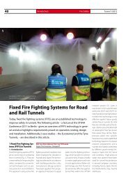
Safety of Life in <strong>Tunnel</strong>s (SOLIT)<br />
Internationale Konferenz SOLIT 2<br />
in Berlin<br />
Zum Thema „Integration von<br />
stationären Brandbekämpfungsanlagen<br />
in <strong>Tunnel</strong>n“ findet<br />
am 27. und 28. Juni 2012<br />
in Berlin die Internationale SO-<br />
LIT-Konferenz (Safety of Life in<br />
<strong>Tunnel</strong>s) statt. Auf dieser zweitägigen<br />
Konferenz werden exklusiv<br />
die Ergebnisse des SO-<br />
LIT²-Forschungsprojektes, das<br />
auf Beschluss des Deutschen<br />
Bundestages gefördert wurde,<br />
vorgestellt. Die an diesem<br />
Projekt beteiligten Partner, der<br />
Projektkoordinator FOGTEC, die<br />
BUNG Ingenieure AG, die STUVA<br />
e.V, die Ruhr Universität Bochum<br />
sowie der TÜV Süd, präsentieren<br />
erstmals am ersten Tag in ausführlichen<br />
Fachvorträgen die<br />
Arbeit der letzten 2 Jahre. Dabei<br />
stehen die Kompensation von<br />
herkömmlichen Sicherheits-<br />
und Brandschutzsystemen<br />
durch automatische Brandbekämpfungsanlagen<br />
sowie deren<br />
Integration in ein <strong>Tunnel</strong>sicherheitssystem<br />
im Vordergrund. Ein<br />
Hauptbestandteil der Vorträge<br />
sind die im Sommer 2011 durchgeführten<br />
Großbrandversuche<br />
sowie die Bewertung der darin<br />
ermittelten Ergebnisse.<br />
Der erste Konferenztag beinhaltet<br />
Vorträge zur Kompensati-<br />
on von Sicherheitsmaßnahmen<br />
durch stationäre Brandbekämpfungsanlagen<br />
sowie der Planung<br />
und Integration von stationären<br />
Brandbekämpfungsanlagen als<br />
Teil eines Sicherheitssystems.<br />
Darüber hinaus wird der Projektbericht<br />
sowie ein Leitfaden<br />
zur Umsetzung der Projektergebnisse<br />
präsentiert.<br />
Am zweiten Tag der Konferenz<br />
wird im Rahmen eines<br />
ITA-COSUF Abschnittes u.a.<br />
über menschliches Verhalten<br />
in <strong>Tunnel</strong>n, das SAFE-Stationen-<br />
Konzept im Eurotunnel sowie<br />
Brandbekämpfung in komplexen<br />
unterirdischen Strukturen<br />
informiert. Den Abschluss bilden<br />
weitere Vorträge, die im Zusammenhang<br />
mit dem Einsatz<br />
von stationären Brandbekämpfungsanlagen<br />
in <strong>Tunnel</strong>n stehen.<br />
Hier stehen Nutzeraspekte der<br />
<strong>Tunnel</strong>sicherheit, Umgang mit<br />
Gefahrgut und Erfahrungen der<br />
Feuerwehren im Fokus.<br />
Für alle Vorträge findet für<br />
den internationalen Teilnehmerkreis<br />
eine Simultanübersetzung<br />
Deutsch/Englisch statt. Weitere<br />
Informationen rund um die Konferenz<br />
in Berlin, das Programm,<br />
Anmeldung und Kosten finden<br />
Sie auf www.solit.info.<br />
Safety of Life in <strong>Tunnel</strong>s (SOLIT)<br />
International Conference SOLIT 2<br />
in Berlin<br />
The International SOLIT Conference<br />
(Safety of Life in <strong>Tunnel</strong>s)<br />
is due to be held in Berlin<br />
on June 27 + 28, 2012: its topic<br />
– “Integration of stationary Fire<br />
Suppression Systems in <strong>Tunnel</strong>s”.<br />
At this 2-day conference the<br />
findings of the SOLIT 2 research<br />
project, which was sponsored at<br />
the behest of the German Bundestag,<br />
will be made public. The<br />
partners involved in the project,<br />
the project coordinator FOGTEC,<br />
BUNG Ingenieure AG, the STUVA<br />
Inc., the Ruhr University Bochum<br />
as well as the TÜV Süd, will for<br />
the first time present extensive<br />
reports on the activities of the<br />
past 2 years on Day 1. Particular<br />
attention will be paid to compensating<br />
conventional safety<br />
and fire protection systems<br />
with automatic fire suppression<br />
systems as well as their integration<br />
in a tunnel safety system.<br />
A major portion of the lectures<br />
programme will be devoted to<br />
the major fire tests undertaken in<br />
summer 2011 as well as the evaluation<br />
of the results obtained<br />
from them.<br />
Day 1 of the conference<br />
hones in on papers dealing with<br />
compensatory safety measures<br />
through stationary fire suppres-<br />
sion systems as well as planning<br />
and integrating stationary fire<br />
suppression systems as part of<br />
a safety system, Furthermore the<br />
project report as well as guidelines<br />
for applying the project<br />
results will be presented.<br />
On Day 2 at the conference<br />
within the scope of an ITA-CO-<br />
SUF section, details will be presented<br />
on among other things<br />
human behaviour in tunnels,<br />
the SAFE stations concept in<br />
the Channel <strong>Tunnel</strong> as well as<br />
combating fire in complex underground<br />
structures. The event<br />
will be completed with further<br />
lectures devoted to applying stationary<br />
fire suppression systems<br />
in tunnels, mainly geared to user<br />
aspects of tunnel safety, handling<br />
hazardous goods and findings<br />
obtained by fire services.<br />
Simultaneous German/English<br />
translations will be provided<br />
for the international circle of participants<br />
for all papers. Further<br />
details on the conference in<br />
Berlin, the programme, registration<br />
and costs can be found by<br />
accessing www.solit.info.<br />
www.solit.info
CREATING TOMORROW’S SOLUTIONS<br />
ETONIS ® – IHR BAUSTEIN<br />
FÜR MEHR KOSTENSICHERHEIT<br />
IM TUNNELBAU<br />
Bei <strong>Tunnel</strong>bauprojekten spielt die Kostensicherheit eine entscheidende Rolle. Ein Kernbaustoff ist der Beton. Mit dem<br />
innovativen Modifi ziermittel ETONIS ® verleihen Sie Spritzbeton Eigenschaften, die Bau- und Folgekosten senken.<br />
Ein Schlüsselmerkmal von ETONIS ® ist die Verbesserung von Adhäsion und Kohäsion. Sprich, der Spritzbeton haftet an<br />
jedem Gestein. Das reduziert den Rückprall signifi kant und damit die Materialkosten. Weitaus größer ist der Einfl uss von<br />
ETONIS ® auf den erhärteten Beton. Durch Absenken des Elastizitätsmoduls bei gleichzeitig hohen Druckfestigkeiten<br />
verleiht ETONIS ® dem Beton duktile Eigenschaften. Das führt zu höheren Zug- und Biegezugfestigkeiten, höherer Bruchdehnung<br />
und geringerer Reißneigung. Zugleich ist mit ETONIS ® modifi zierter Beton beständig gegen CO 2 , Salze und<br />
Säuren. Das bringt auch langfristig Kostensicherheit.<br />
Wie Sie mit ETONIS ® die Kosten besser im Griff behalten können, erläutern wir Ihnen<br />
gerne in einem Gespräch: Infoline +49 8677 83-7979 oder info.polymers@wacker.com<br />
www.wacker.com/etonis
8 Nachrichten<br />
News <strong>Tunnel</strong> 3/2012<br />
Weiterbildung <strong>Tunnel</strong>sanierung<br />
Workshop am 4. Juni 2012 an der RUB<br />
Wurde in den vergangenen Jahrzehnten<br />
der überwiegende Teil<br />
der im unterirdischen Bauen aufgewendeten<br />
Investitionen noch<br />
in den Ausbau von Infrastruktur<br />
investiert, so gewinnt das sogenannte<br />
„Bauen im Bestand“ auch<br />
für den <strong>Tunnel</strong>bau zunehmend<br />
an Bedeutung. Vor allem im Bereich<br />
der Bahntunnel, wo rund<br />
die Hälfte des Bauwerksbestandes<br />
bereits das Ende der rechnerischen<br />
Lebensdauer erreicht<br />
hat, hat sich in den vergangenen<br />
Jahren ein großer Handlungsbedarf<br />
herausgebildet. Dies wird<br />
unter anderem auch durch die<br />
tunnel-Sonderausgabe „Sanierung<br />
von Eisenbahntunneln“<br />
zum Sachstand 2011 in diesem<br />
Bereich dokumentiert. Diese<br />
Sonderausgabe wurde zur vergangenen<br />
STUVA-Tagung im<br />
Dezember 2011 in Zusammenarbeit<br />
mit dem STUVA-Arbeitskreis<br />
„<strong>Tunnel</strong>sanierung“ herausgegeben.<br />
Doch auch im Bereich der<br />
Straßen- und U-Bahntunnel<br />
entwickelt sich ein deutlich erkennbarer<br />
Sanierungsbedarf,<br />
der Betreiber und Industrie in<br />
den nächsten Jahrzehnten gleichermaßen<br />
beschäftigen wird.<br />
Eine technisch wie wirtschaftlich<br />
effiziente Sanierung von<br />
<strong>Tunnel</strong>bauwerken steht künftig<br />
ganz unabhängig vom Verkehrsträger<br />
mehr und mehr im Fokus<br />
der Betrachtung.<br />
Am 4. Juni 2012 fi ndet aus<br />
diesem Grund an der Ruhr-Universität<br />
Bochum ein Symposium<br />
statt, welches sich diesem Thema<br />
eingehender widmet und den<br />
Teilnehmern einen umfassenden<br />
Überblick über die künftigen<br />
Herausforderungen wie auch<br />
den Stand der Entwicklungen<br />
im Bereich <strong>Tunnel</strong>sanierungen<br />
näher bringt. Vertreter aller 3<br />
unterirdischer Verkehrsträger<br />
(Schiene, U-Bahn und Straße)<br />
schildern Bedürfnisse und Strategien<br />
im Sanierungsbereich auf<br />
Basis umfassender Bestandsanalysen.<br />
Darüber hinaus werden<br />
den Teilnehmern technische<br />
und wirtschaftliche Konzepte zur<br />
Instandhaltung vermittelt und<br />
anschließend diskutiert.<br />
Nach kurzer Einführung<br />
wird Prof. Dr.-Ing. Markus Thewes<br />
durch den Tag moderieren.<br />
Prof. Alfred Haack wird eine<br />
Projektübersicht aus dem AK<br />
<strong>Tunnel</strong>sanierung geben und<br />
Dipl.-Ing. Stefan Simon von der<br />
DB Projektbau wird über den<br />
Bedarf und die jüngsten Erfahrungen<br />
bei der Nachrüstung<br />
von Eisenbahntunneln berichten.<br />
Ihm folgend werden Dr.-Ing.<br />
Frank Heimbecher und Dipl.-<br />
Ing. Ingo Kaundinya Bedarf,<br />
Erfahrungen und jüngste Forschungen<br />
bei der Nachrüstung<br />
von Straßentunneln erläutern.<br />
Den Bedarf und die Strategie bei<br />
der Sanierung innerstädtischer<br />
U-Bahntunnel erklärt Dipl.-Ing.<br />
Uwe Kutscher von den Berliner<br />
Verkehrsbetrieben. Prof. Markus<br />
Thewes mit Dr.-Ing. Götz<br />
Vollmann von der RUB zeigen<br />
Schadensbilder und Life Cycle<br />
Management auf und schließlich<br />
informieren Dipl.-Ing. (FH)<br />
Thomas Edelmann und Dipl.-<br />
Ing. (FH) Volker Breuning von<br />
Herrenknecht über neue Technologien.<br />
Informationen zum Programm,<br />
den genauen Veranstaltungsort<br />
und den Kosten<br />
erhalten Sie unter Telefon: +49-<br />
(0)2 34-3 22 60 81 oder E-Mail:<br />
tlb-conference@rub.de. Unter<br />
der E-Mail-Adresse können Sie<br />
sich auch direkt anmelden.<br />
Further Training – <strong>Tunnel</strong> Redevelopment<br />
Workshop on June 4, 2012 at the RUB<br />
In recent decades the major portion<br />
of the investments poured<br />
into underground construction<br />
has been earmarked for infrastructure.<br />
However, what is<br />
known as upgrading existing<br />
structures is also becoming<br />
increasingly signifi cant for tunnelling.<br />
Above all on the rail tunnel<br />
sector where roughly the half<br />
of the existing structures have reached<br />
the end of their intended<br />
service life, an enormous need<br />
for redevelopment has emerged.<br />
This is documented for example<br />
in the special tunnel issue “Redeveloping<br />
Rail <strong>Tunnel</strong>s” from 2011<br />
dealing with the situation in this<br />
fi eld. This special issue was made<br />
available at the latest STUVA<br />
Conference in December 2011<br />
in collaboration with the STUVA<br />
working group on “<strong>Tunnel</strong> Redevelopment”.<br />
However a clearly discernible<br />
need for redevelopment in the<br />
fi eld of road and Metro tunnels<br />
is also becoming evident, which<br />
will preoccupy both operators<br />
and industry to an equal extent<br />
in decades to come. Regardless<br />
of the organisations involved<br />
technically and economically<br />
effi cient upgrading of tunnels<br />
will be increasingly at the centre<br />
of attention.<br />
As a result a symposium is<br />
being staged at the Ruhr University<br />
Bochum on June 4, 2012,<br />
which will be devoted to this<br />
topic thus providing the participants<br />
with a comprehensive<br />
overview of future challenges as<br />
well as the latest stage reached<br />
by developments in the fi eld of<br />
upgrading tunnels. Representatives<br />
of all 3 bodies engaged with<br />
underground transportation (rail,<br />
Metro and road) will describe<br />
requirements and strategies for<br />
upgrading based on extensive<br />
analyses of the existing facilities.<br />
Furthermore the participants will<br />
be provided with technical and<br />
economic maintenance concepts,<br />
which will subsequently<br />
be discussed.<br />
Following a short introduction,<br />
Prof. Markus Thewes will<br />
chair the event throughout the<br />
day; Prof. Alfred Haack will provide<br />
a project overview from<br />
the working group on tunnel<br />
redevelopment viewpoint and<br />
Dipl.-Ing. Stefan Simon from the<br />
DB ProjektBau will report on the<br />
need and latest fi ndings in upgrading<br />
rail tunnels. Then Dr.-Ing.<br />
Frank Heimbecher and Dipl.-Ing.<br />
Ingo Kaundinya will deal with<br />
needs, experiences and the latest<br />
research in conjunction with upgrading<br />
road tunnels. Dipl.-Ing.<br />
Uwe Kutscher from the Berliner<br />
Verkehrsbetrieben will explain<br />
the need and strategy for upgrading<br />
urban Metro tunnels. Prof.<br />
Markus Thewes together with<br />
Dr.-Ing. Götz Vollmann from the<br />
RUB will tackle damage scenarios<br />
and life cycle management before<br />
Dipl.-Ing. (FH) Thomas Edelmann<br />
and Dipl.-Ing. (FH) Volker<br />
Breuning from Herrenknecht<br />
examine new technologies.<br />
Details relating to the programme,<br />
the exact venue and<br />
the costs are available by contacting<br />
phone +49-(0)2 34-3 22<br />
60 81 or e mail tlb-conference@<br />
rub.de. For registration just send<br />
an e mail.
RELIABLE � RESPONSIVE<br />
���ROBBINS�����������<br />
WHY SETTLE FOR A DISMANTLED TBM?<br />
���������������������������������������������������������������<br />
�����������������������������������������������������������<br />
���������������������������������������������������������������<br />
�����������������������������������������������������������������<br />
���������������������������������������������������������������
10 Nachrichten<br />
News <strong>Tunnel</strong> 3/2012<br />
Das Besondere Projekt<br />
Impuls-Vortrag von Heinz Ehrbar<br />
in München/D<br />
Der Gotthard ist in der Schweiz<br />
ein Mythos. Jahrhundertelange<br />
Entwicklungen und geschichtlich<br />
bedeutende Ereignisse bis<br />
hin zur Gründung der Schweiz<br />
sind mit diesem Gebiet verbunden.<br />
In den 30er Jahren des letzten<br />
Jahrhunderts wurden erste<br />
Ideen eines Basistunnels entwickelt.<br />
Zu Beginn der 1970er<br />
Jahre wurde dann die Idee<br />
eines Eisenbahn-Basistunnels<br />
anstelle des Autobahntunnels<br />
wieder aufgenommen – jedoch<br />
ohne Erfolg.<br />
Die spürbaren negativen<br />
Auswirkungen des Straßenverkehrs<br />
in den engen Alpentälern<br />
verlangten nach der Eröffnung<br />
des Straßentunnels<br />
im Jahr 1980 nach einem Eisenbahn-Basistunnel.<br />
In einer<br />
Entscheidungsfindung, wie<br />
sie wohl nur in der direkten<br />
Demokratie möglich ist, wurde<br />
1992 das Projekt an sich<br />
beschlossen und 1998 eine<br />
stabile Finanzierung sichergestellt.<br />
2002 begannen die<br />
Hauptarbeiten. Am 15. Oktober<br />
2010 war der Berg bezwungen.<br />
Ende 2016 ist die<br />
Inbetriebnahme geplant.<br />
Die langjährige Geschichte<br />
gibt uns einmalige Erkenntnisse<br />
mit auf den Weg, welche<br />
es für andere Großprojekte zu<br />
beherzigen gilt. Aus diesem<br />
Grund wurde Heinz Ehrbar,<br />
Leiter <strong>Tunnel</strong>- und Trasseebau<br />
Gotthard und Mitglied der Geschäftsleitung<br />
der AlpTransit<br />
Gotthard AG, Luzern/CH, zu<br />
einem Impulsvortrag nach<br />
München in das Oskar von<br />
Miller Forum eingeladen.<br />
Das Oskar von Miller Forum<br />
wird von der Stiftung<br />
Bayerisches Baugewerbe be-<br />
trieben und kann auf die Unterstützung<br />
der Bayerischen<br />
Baugewerbeverbände, des<br />
Bayerischen Bauindustrieverbandes,<br />
der IndustriegewerkschaftBauen-Agrar-Umwelt<br />
sowie des Verbandes der<br />
Zimmerer und<br />
Holzbauunternehmer<br />
Bayern<br />
bauen. Ziel des<br />
Oskar von Miller<br />
Forums ist es,<br />
der Hochschulbildung<br />
der Ingenieure<br />
und<br />
der Ausbildung<br />
der Meisterschüler<br />
im Bauwesen<br />
interdisziplinär und international<br />
ausgerichtete Impulse zu<br />
geben. Dies geschieht mit ausgewählten<br />
Themen in Form<br />
der sogenannten Impulsvorträge.<br />
Sie sind interdisziplinär,<br />
interkulturell und innovativ<br />
angelegt, konzentrieren sich<br />
auf aktuelle Leitthemen der<br />
Ingenieurwissenschaften und<br />
anderer technischer, baubezogener<br />
Bereiche. Sie lösen neue<br />
Impulse aus und fördern den<br />
fachlichen Austausch. Bei den<br />
Impulsvorträgen handelt es<br />
sich um international hochrangige<br />
Themenvorträge, die<br />
langfristig geplant werden.<br />
Der Impulsvortrag „Gotthard-Basistunnel:<br />
„Der längste<br />
Eisenbahntunnel der Welt; 60<br />
Jahre Vision – 20 Jahre Realisierung“<br />
fand am 19. April<br />
2012 im Oskar von Miller Forum<br />
in München statt.<br />
Weitere Informationen auf<br />
www.oskarvonmillerforum.<br />
de/programm/impulsvortraege.html.<br />
The special Project<br />
Impulse Lecture by Heinz Ehrbar<br />
in Munich/D<br />
The Gotthard is a myth in Switzerland.<br />
Developments spanning<br />
centuries and historically<br />
significant events right up to the<br />
founding of Switzerland are associated<br />
with this region. During<br />
the 1930s, the initial proposals<br />
for a Base <strong>Tunnel</strong><br />
were developed.<br />
In the early 1970s<br />
the concept of a<br />
railway Base <strong>Tunnel</strong><br />
was contemplated<br />
instead of a<br />
motorway tunnel<br />
– however<br />
without success.<br />
The perceptively<br />
negative<br />
effects of road traffic in the narrow<br />
Alpine valleys following the<br />
opening of the road tunnel in<br />
1980 called for a railway Base<br />
<strong>Tunnel</strong>. In a decision-making<br />
process, which is only possible<br />
through direct democracy, the<br />
project was given the green<br />
light in 1992 and a stable programme<br />
to finance it evolved<br />
in 1998. The main construction<br />
work commenced in 2002. On<br />
October 15, 2010 the mountain<br />
was finally conquered. The opening<br />
is planned for late 2016.<br />
The many years of history<br />
provide us with unique recognitions,<br />
which relate to other<br />
major projects. As a result,<br />
Heinz Ehrbar, who heads <strong>Tunnel</strong>-<br />
und Trasseebau Gotthard<br />
and is a member of the executive<br />
of the AlpTransit Gotthard<br />
AG, Lucerne/CH, was invited to<br />
present an Impulse Lecture in<br />
Munich at the Oskar von Miller<br />
Forum.<br />
The Oskar von Miller Forum<br />
is run by the Bavarian Construction<br />
Trade Foundation and<br />
is supported by the Bavarian<br />
Construction Trade Associations,<br />
the Bavarian Construction<br />
Industry Association, the<br />
Construction, Agriculture and<br />
Environment Industrial Trade<br />
Union as well as the Bavarian<br />
Association of Carpenters and<br />
Timber Merchants. The Oskar<br />
von Miller Forum’s aim is to<br />
provide internationally geared<br />
impulses for university education<br />
for engineers and teaching<br />
master pupils in the construction<br />
industry at interdisciplinary<br />
level. This is pursued through<br />
selected topics taking the form<br />
of what are known as Impulse<br />
Lectures. They possess an interdisciplinary,<br />
intercultural and<br />
innovative structure and hone<br />
in on topical themes stemming<br />
from engineering sciences and<br />
other technical spheres related<br />
to construction. They trigger<br />
new impulses and promote<br />
an exchange of views among<br />
peers. The Impulse Lectures are<br />
international top-grade lectures<br />
dealing with topics, which have<br />
been planned well in advance.<br />
The Impulse Lecture: ”Gotthard<br />
Base <strong>Tunnel</strong>: The World’s<br />
longest Railway <strong>Tunnel</strong>; 60 Years<br />
of Vision – 20 Years of Realisation“<br />
was held in April 2012 at<br />
the Oskar von Miller Forum in<br />
Munich.<br />
Further details are available by<br />
accessing www.oskarmillerforum.de/programm/impulsvortraege.html
tunnel now as<br />
eMagazine!<br />
Your advantages at<br />
a glance:<br />
• available worldwide<br />
• benefit from the lucid presentation in<br />
the familiar layout of the printed issue<br />
• easy full text search<br />
• straightforward navigation on<br />
individual pages or items<br />
• the provided links enable<br />
you to obtain more details on<br />
corresponding topics in a jiffy<br />
• no delays due to protracted<br />
dispatch<br />
Go online wherever you are!<br />
www.tunnel-online.info<br />
Subscribe<br />
now –<br />
98.50 EUR<br />
per year!
12 Nachrichten<br />
News <strong>Tunnel</strong> 3/2012<br />
InnoTrans 2012 in Berlin<br />
Blick in die Zukunft der Mobilität<br />
Mit welchen Produktinnovationen<br />
und Dienstleistungen<br />
reagieren Bahnindustrie und<br />
Hersteller von <strong>Tunnel</strong>bautechnik<br />
auf die Herausforderungen<br />
der Mobilität? Lassen sich<br />
schillernde Schlagwörter wie<br />
Interoperabilität, intermodale<br />
Verkehrslösungen und nachhaltige<br />
ÖPNV-Konzepte in konkrete<br />
Produkte übertragen und<br />
auf einer Messe begutachten?<br />
Die Antwort ist ja. Auf der InnoTrans<br />
2012 in Berlin erhalten<br />
Aussteller und Fachbesucher<br />
vom 18. bis 21. September einen<br />
Überblick über den Markt<br />
der Bahnbranche und können<br />
zudem einen informativen Blick<br />
in die Zukunft der Mobilität<br />
werfen.<br />
Ein Messebesuch in diesem<br />
Jahr lohnt sich besonders, denn<br />
die internationale Bahnindustrie<br />
hat sich noch nie zuvor so umfangreich<br />
in Berlin präsentiert.<br />
Die Hallen-Ausstellungsfläche<br />
der vorherigen Veranstaltung<br />
ist weit überschritten, selbst<br />
zusätzlich erschlossene Hallen-Kapazitäten<br />
sind ausgebucht.<br />
Dabei fällt besonders<br />
die hohe Messebeteiligung<br />
asiatischer Unternehmen ins<br />
Auge. Bezugnehmend auf die<br />
Vergleichswerte der InnoTrans<br />
2010 haben Firmen aus Asien<br />
etwa 40 % mehr Ausstellungsfläche<br />
gebucht. Exemplarisch dafür<br />
steht Japan. Die japanische<br />
Bahnindustrie hat eine eigene<br />
Ausstellungshalle gebucht. Ein<br />
Land in einer Halle – das gab es<br />
auf der InnoTrans noch nie.<br />
Internationalität auch<br />
im Segment <strong>Tunnel</strong><br />
Construction<br />
International ist auch die Beteiligung<br />
im Segment <strong>Tunnel</strong><br />
Construction. So präsentiert<br />
beispielsweise erstmalig die<br />
Palmieri Group aus Italien ihre<br />
Produkte auf der InnoTrans.<br />
Das Unternehmen produziert<br />
sowohl spezielle Schmiedeteile<br />
als auch Maschinen für den<br />
<strong>Tunnel</strong>bau und die Wartung<br />
von <strong>Tunnel</strong>anlagen. „Für unsere<br />
Firma stellt die Messe InnoTrans<br />
eine wichtige Werbeplattform<br />
dar. Wir erwarten auf alle Fälle<br />
einen höheren Bekanntheitsgrad.<br />
Auch neue Kontakte bzw.<br />
Lieferantenaufträge für unsere<br />
geschmiedeten und gewalzten<br />
Komponenten stehen im Fokus<br />
der Messeteilnahme“, erklärt<br />
Stefano Palmieri, Sales Manager<br />
der Palmieri Group.<br />
Neben einer Vielzahl deutscher<br />
Firmen sind auch Aussteller<br />
aus der Schweiz, Spanien und<br />
Großbritannien auf der Messe<br />
zugegen. Schon seit mehreren<br />
Jahren stellt die österreichische<br />
Firma bst Brandschutztechnik<br />
Döpfl GmbH (bst) auf der Inno-<br />
Trans ihre Produkte im Bereich<br />
Kabel- und Rohrdurchführung<br />
sowie spezielle Abdichtungen<br />
und Verkleidungen für den<br />
<strong>Tunnel</strong>bau aus. Das Wiener<br />
InnoTrans 2012 in Berlin<br />
Look at the Future of Mobility<br />
Which production innovations<br />
and services are being introduced<br />
by the railway industry and<br />
the manufacturers of tunnelling<br />
technology to counter the challenges<br />
of mobility? Inspiring<br />
catch phrases such as interoperability,<br />
intermodal transport<br />
solutions and sustainable<br />
commuter transportation concepts<br />
translated into concrete<br />
products and put on view at a<br />
fair? The answer is yes. At the InnoTrans<br />
2012 in Berlin exhibitors<br />
and trade visitors will be able to<br />
obtain an overview of the market<br />
from September 18 to 21 and in<br />
addition will gain an insight of<br />
the future of mobility.<br />
Visiting the fair this year is<br />
especially worthwhile for never<br />
before has the international railway<br />
industry been so extensively<br />
represented in Berlin. The amount<br />
of hall space occupied the last<br />
time around has been gobbled<br />
up and further capacities have<br />
already been booked out. The<br />
high proportion of Asian participation<br />
at the fair is eye-catching.<br />
Compared to the InnoTrans 2010<br />
Asian companies have reserved<br />
roughly 40 % additional floor<br />
space. Japan leads the way. The<br />
Japanese railway industry has<br />
booked its own exhibition hall. A<br />
country occupying a whole hall<br />
by itself – a first at the InnoTrans.<br />
Internationality on the<br />
<strong>Tunnel</strong> Construction<br />
Segment as well<br />
Participation in the <strong>Tunnel</strong> Construction<br />
segment is also marked<br />
by being international. For instance<br />
the Palmieri Group from<br />
Italy is displaying its products at<br />
the InnoTrans for the first time.<br />
The company produces special<br />
forged parts as well as machines<br />
for tunnelling and the maintenance<br />
of tunnel installations. “The<br />
InnoTrans exhibition represents<br />
an important advertising platform<br />
for our company. We are certainly<br />
expecting a high degree of identification.<br />
Our participation at the<br />
fair focuses on new contracts and<br />
orders from clients for our forged<br />
and rolled components”, says Stefano<br />
Palmieri, the Palmieri Group’s<br />
Sales Manager.<br />
Apart from a large number of<br />
German firms there are also exhibitors<br />
from Switzerland, Spain<br />
and the United Kingdom present
<strong>Tunnel</strong> 3/2012<br />
Unternehmen schätzt die InnoTrans<br />
als weltgrößtes Branchenereignis.<br />
Martin E. Uhlig,<br />
bst-Verkaufsdirektor: „Die Fachmesse<br />
InnoTrans hat sich als<br />
Treffpunkt der internationalen<br />
Eisenbahn-Fachwelt entwickelt.<br />
Deshalb stellt bst auch heuer<br />
wieder das gesamte Produkt-<br />
Portfolio aus.“<br />
<strong>Tunnel</strong>bautechnik auf<br />
der InnoTrans<br />
Auf der InnoTrans präsentieren<br />
Firmen ihre Bauprodukte und<br />
-materialien, leistungsstarke<br />
<strong>Tunnel</strong>bohrmaschinen sowie<br />
Ingenieurdienstleistungen<br />
für den <strong>Tunnel</strong>bau oder die<br />
<strong>Tunnel</strong>wartung. Das Segment<br />
<strong>Tunnel</strong> Construction profitiert<br />
auf der Fachschau von der<br />
www.normet.fi<br />
www.taminternational.com<br />
Nachrichten News<br />
13<br />
thematischen Nähe zum Segment<br />
Railway Infrastructure.<br />
Hintergrundwissen und aktuelle<br />
Informationen bietet das<br />
von der Studiengesellschaft für<br />
unterirdische Verkehrsanlagen<br />
(STUVA e.V.) durchgeführte<br />
International <strong>Tunnel</strong> Forum.<br />
Weitere Informationen über<br />
die InnoTrans und aktuelle<br />
Entwicklungen in der internationalen<br />
Verkehrstechnik unter<br />
www.innotrans.de<br />
at the exhibition. For a number<br />
of years now the Austrian company<br />
bst Brandschutztechnik<br />
Döpfl GmbH (bst) has shown<br />
its products in the field of cable<br />
and pipe fittings as well as<br />
special seals and linings for tunnelling.<br />
The Viennese enterprise<br />
appreciates the InnoTrans as the<br />
industry’s world’s biggest event<br />
of its kind. Martin E. Uhlig, bst<br />
Sales Director: “The InnoTrans<br />
fair has developed into the meeting<br />
place for the international<br />
railway trade. As a result, bst is<br />
continuing to exhibit its entire<br />
product range”.<br />
<strong>Tunnel</strong>ling Technology<br />
at the InnoTrans<br />
At the InnoTrans companies will<br />
present their construction pro-<br />
SOLUTIONS FOR TOUGH JOBS<br />
ducts and materials, powerful<br />
tunnelling machines as well as<br />
engineering services for tunnelling<br />
or servicing tunnels. The<br />
<strong>Tunnel</strong> Construction Segment<br />
profits at the exhibition from<br />
its proximity to the Railway Infrastructure<br />
Segment. Background<br />
knowledge and topical<br />
information will be provided by<br />
the International <strong>Tunnel</strong> Forum<br />
presented by the Research Association<br />
for Underground Transportation<br />
Facilities (STUVA Inc.).<br />
Further details on the InnoTrans<br />
and current developments on international<br />
transport technology<br />
are available by accessing www.<br />
innotrans.de<br />
www.innotrans.de<br />
NOR_120224_ImageAd50_TunMag_186x130.indd 1 24.02.12 10:11<br />
www.coray.com
14 Nachrichten<br />
News <strong>Tunnel</strong> 3/2012<br />
Neue Ingenieurbau-Messe in Freiburg/D<br />
Ingenieurbautage: Wenn das Auge<br />
im All unter die Erde späht....<br />
Die Vorbereitungen für die<br />
neue Ingenieurbaumesse<br />
econstra laufen auf Hochtouren.<br />
Ein besonderes Thema der<br />
Ingenieurbautage mit ausgewählten<br />
Fachvorträgen, die im<br />
Rahmen der econstra – expo of<br />
construction engineering auf<br />
dem Freiburger Messegelände<br />
(25. bis 27. Oktober 2012) angeboten<br />
werden, haben wir einmal<br />
im folgenden Interview näher<br />
betrachtet. Am 26. Oktober<br />
von 10.15 bis 11.00 Uhr meldet<br />
sich dort EADS Astrium GEO-<br />
Information Services zu Wort:<br />
„Aus dem All zum <strong>Tunnel</strong> - Millimetergenaue<br />
Faszination der<br />
interferometrischen Bodenbewegungsüberwachung“<br />
heißt<br />
das Vortragsthema.<br />
Wie das genau funktionieren<br />
soll, sollten Sie sich im Vortrag<br />
selbst anhören. Um aber schon<br />
einmal neugierig zu machen,<br />
haben wir mit Dr. Lutz Petrat,<br />
Product Line Manger Monitoring<br />
Services von Astrium,<br />
einer Tochter von EADS, gesprochen.<br />
Wie entstand die Idee, aus<br />
dem All Vermessungen am<br />
Boden vorzunehmen und seit<br />
wann wird dies angewandt?<br />
Das Verfahren ist bereits seit<br />
einigen Jahren bekannt, Ergebnisse<br />
wurden mit den Satelliten<br />
Seasat und Sir-A/B in den<br />
1980er und 1990er Jahren erzielt.<br />
Die Technik gewann aber<br />
erst dann an Bedeutung als der<br />
Satellit ERS-1 der Europäischen<br />
Raumfahrtagentur ESA 1992<br />
in Dienst gestellt wurde und<br />
damit auch über Nachfolgesysteme<br />
(ERS-2, ENVISAT) entsprechende<br />
satellitengestützte<br />
Radardaten leicht verfügbar<br />
waren. Kommerzielle Überwachungsanwendungen<br />
wurden<br />
insbesondere durch kommerzielle<br />
Satellitensysteme wie<br />
TerraSAR-X gefördert.<br />
Wer wendet diese neue Technologie<br />
an?<br />
Öl- und Erdgasfirmen, Bergbauunternehmen,<br />
Bauherren<br />
und –unternehmer: es kommt<br />
jede Art der Anwendung in Frage,<br />
die in irgendeiner Art und<br />
Weise mit Bodenbewegungen<br />
zu tun hat.<br />
Welche Geräte oder Einrichtungen<br />
benötigt man eigentlich,<br />
um diese Technologie<br />
anwenden zu können?<br />
Einen oder mehrere Radarsatelliten<br />
und entsprechende<br />
interferometrische Prozessiersoftware,<br />
die aus den Phaseninformationen<br />
zweier Radardatensätze<br />
Phasendifferenzen<br />
berechnet, die nach entsprechender<br />
Korrektur in Bodenbewegungen<br />
konvertiert werden<br />
können.<br />
Das hört sich ja sehr nach<br />
„Terminator“ an: Was bedeutet<br />
dabei „interferometrisch“?<br />
Interferometrische Prozessierung<br />
bedeutet, dass die kom-<br />
New Construction Engineering Fair in Freiburg/D<br />
Construction Engineering Event:<br />
Eye in Space peering below Ground...<br />
The preparations for the new<br />
construction engineering fair<br />
econstra are forging ahead. A<br />
special topic at the construction<br />
engineering congress with<br />
selected lectures, at the econstra<br />
– the expo of construction<br />
engineering at the Freiburg<br />
fairgrounds (October 25 – 27,<br />
2012) is examined more closely<br />
in the following interview.<br />
EADS Astrium GEO-Information<br />
Services takes to the podium<br />
there on October 26 from<br />
10.15 till 11.00 am: “From Space<br />
to the <strong>Tunnel</strong> – Fascination of<br />
interferometric Soil Movement<br />
Monitoring accurate to the<br />
Millimetre” is how the lecture<br />
is captioned.<br />
Just how that actually functions<br />
is something you can find<br />
out at the lecture itself. However<br />
to whet your appetite we spoke<br />
to Dr. Lutz Petrat, Product Line<br />
Manager Monitoring Services of<br />
Astrium, an EADS subsidiary.<br />
How did the idea of carrying<br />
out ground surveying from<br />
space originate and since<br />
when has this been applied?<br />
The method’s been known for<br />
some years now, results were<br />
attained during the 1980s and<br />
90s with the Seasat and Sir-A/B<br />
satellites. However the technology<br />
first really became significant<br />
after the ERS-1 satellite was put<br />
into service by the European<br />
Space Agency ESA in 1992 so<br />
that corresponding satellite-supported<br />
radar data were also easily<br />
available via follow-up systems<br />
(ERS-2, ENVISAT). Commercial<br />
monitoring applications were<br />
particularly promoted thanks<br />
to commercial satellite systems<br />
such as TerraSAR-X.<br />
Who uses these new technologies?<br />
Oil and natural gas companies,<br />
mining companies, construction<br />
clients and contractors: potentially<br />
every kind of application associated<br />
in some way or another<br />
with soil movements.<br />
Which appliances or installations<br />
do you actually need to<br />
apply these technologies?<br />
One or several radar satellites<br />
and corresponding interferometric<br />
processing software, calculating<br />
phase differences from<br />
the phase data of 2 radar data<br />
sets, which can be converted<br />
into soil movements following<br />
corresponding correction.<br />
That sound rather like “Terminator”:<br />
what does “interferometric”<br />
actually mean in<br />
this case?<br />
Interferometric processing<br />
means that the complex data<br />
from at least 2 radar recordings<br />
(taken at point 1 and point 2) are<br />
multiplied with each other in a<br />
complex conjugated manner for<br />
each individual pixel in the recording.<br />
This results among other<br />
things in a phase difference<br />
between the 2 recordings,<br />
which contains information on<br />
the soil movement taking place<br />
between the 2 recording points<br />
quite apart from many other<br />
things.<br />
And how is it possible now to<br />
peek under the earth and determine<br />
the exact alignment<br />
of a tunnel from “above”?<br />
During all tunnelling activities<br />
generally speaking small (several<br />
millimetres) to larger soil movements<br />
(several centimetres) oc-
<strong>Tunnel</strong> 3/2012<br />
plexen Daten von mindestens<br />
2 Radaraufnahmen (aufgenommen<br />
zum Zeitpunkt 1 und<br />
Zeitpunkt 2) für jedes einzelne<br />
Pixel in der Aufnahme komplex<br />
konjugiert miteinander multipliziert<br />
werden. Es ergibt sich<br />
daraus u.a. eine Phasendifferenz<br />
zwischen den beiden<br />
Aufnahmen in der neben vielen<br />
anderen die Information<br />
über eine zwischen den beiden<br />
Aufnahmezeitpunkten stattgefundene<br />
Bodenbewegung enthalten<br />
ist.<br />
Und wie kann man jetzt aus<br />
dem All unter die Erde sehen<br />
und von „oben“ den genauen<br />
Verlauf eines <strong>Tunnel</strong>s festlegen?<br />
Bei allen <strong>Tunnel</strong>arbeiten treten<br />
in der Regel kleine (wenige<br />
Millimeter) bis größere<br />
Bodenbewegungen (mehrere<br />
Zentimeter) an der Oberfläche<br />
auf - einmal durch die Erstellung<br />
des Hohlraums an sich,<br />
zum anderen aber auch durch<br />
notwendige Eingriffe in den<br />
Grundwasserspiegel. Es ist damit<br />
nicht der <strong>Tunnel</strong> selbst zu<br />
sehen, sondern eher das „Bodenbewegungssignal“<br />
des <strong>Tunnel</strong>s<br />
an der Oberfläche - wenn<br />
er kein Signal hinterlässt, ist er<br />
auch nicht zu sehen.<br />
Gibt es Fehlerquellen bzw.<br />
Beeinträchtigungen dabei?<br />
Die größte Fehlerquelle sind<br />
atmosphärische Einflüsse, die<br />
allerdings durch statistische<br />
Mittel und die Aufnahme ei-<br />
Nachrichten News<br />
15<br />
ner Vielzahl von Daten weitestgehend<br />
reduziert werden<br />
können. Hintergrund ist, dass<br />
auch größere Änderungen<br />
im Wasserdampfgehalt in der<br />
Atmosphäre (z.B. durch den<br />
Durchzug einer Gewitterfront)<br />
bei einer Aufnahme im<br />
Vergleich zu einer weiteren<br />
Aufnahme ein einer Bodenbewegung<br />
sehr ähnliches Signal<br />
erzeugen kann. Man erkennt<br />
solche fälschlichen „Bodenbewegungen“<br />
in der Regel schon<br />
daran, dass sie in einem Aufnahmegebiet<br />
nicht räumlich<br />
stabil an einem Ort sondern<br />
zufällig verteilt sind.<br />
Und was kostet es jetzt,<br />
einen <strong>Tunnel</strong> aus dem All zu<br />
„betreuen“?<br />
Ein operatives Monitoring während<br />
der <strong>Tunnel</strong>bauphase startet<br />
mit ca. 50.000 Euro pro Jahr<br />
bei einer jährlichen Prozessierung<br />
der vorhandenen Daten<br />
und einem jährlichen Update<br />
über Bodenbewegungen, z.B.<br />
zum Backup eines konventionellen<br />
Monitorings. Sollen<br />
häufigere Updates der Ergebnisse<br />
erfolgen, müssen höhere<br />
Preise veranschlagt werden, da<br />
in diesem Fall häufigere Prozessierungen<br />
durchgeführt werden<br />
müssen.<br />
Genauere Informationen bieten<br />
wir mit EADS Astrium GEO-Information<br />
Services auch auf der<br />
econstra – expo of construction<br />
engineering im Oktober auf unserem<br />
Stand an.<br />
cur on the surface – first of all on<br />
account of the cavity being produced<br />
and secondly also owing<br />
to the necessary intervention in<br />
the groundwater level. It is not<br />
the tunnel itself that is seen but<br />
rather the “soil movement signal”<br />
of the tunnel on the surface – if<br />
it does not leave a signal, it also<br />
cannot be seen.<br />
Are there associated sources<br />
of error or drawbacks?<br />
The greatest source of error are<br />
atmospheric influences, which<br />
can however be largely reduced<br />
by statistical means and recording<br />
a large number of data.<br />
The background is that major<br />
changes in the water vapour<br />
content in the atmosphere (e.g.<br />
resulting from the passage of a<br />
storm front) can produce a very<br />
similar signal to a soil movement<br />
during a recording in comparison<br />
to another recording. Generally<br />
such false “soil movements”<br />
are identified because they are<br />
not spatially stable at one place<br />
but are distributed at random<br />
within a recording zone.<br />
And what does it now cost to<br />
“mind” a tunnel from space?<br />
Operative monitoring during the<br />
tunnelling phase starts at roughly<br />
50,000 euros per year given annual<br />
processing of the existing<br />
data and an annual update on<br />
soil movements, e.g. to backup<br />
conventional monitoring. If more<br />
frequent updates of the results<br />
are necessary, higher prices are<br />
then involved as in this case<br />
�������������������������������������������������������������<br />
No rust. No corrosion. No creeping. No danger of injuries. Excellent working capacity.<br />
more frequent processing has<br />
to be undertaken.<br />
More exact details are also available<br />
from EADS Astrium GEO-Information<br />
Services at the econstra<br />
– expo of construction engineering<br />
in October at our booth.<br />
www.bruggcontec.ch<br />
www.econstra.de
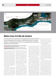
16 Thailand Bangkok<br />
<strong>Tunnel</strong> 3/2012<br />
Long Term Flood Prevention in<br />
Chaophaya Basin, Thailand<br />
In May 2012 Bangkok in Thailand is the venue for the ITA/WTC conference.<br />
In the capitol of Thailand are a lot of interesting tunnelling projects, but<br />
one of the most important problems is shown in this article: What is to do<br />
against a flood like in 2011?<br />
Thailand Underground and <strong>Tunnel</strong>ling Group<br />
Thailand’s Most Severe<br />
Flood Crisis 2011<br />
2011 flood crisis in Bangkok and<br />
other major provinces is considered<br />
the worst natural disaster<br />
in recent Thai history. With damage<br />
totaling 1,000 Billion Baht,<br />
adverse impact of this disaster<br />
is extremely significant for Thai<br />
economy and daily life of the citizens.<br />
There are also intangible<br />
damages apart from the tangible<br />
losses.<br />
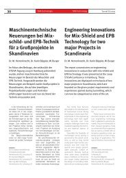
1<br />
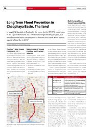
Western Outer Ring Road<br />
Major Causes of Severe<br />
Flooding and Practical<br />
Solution<br />
There are several factors contributed<br />
to the severe flooding in<br />
upstream provinces and Bangkok<br />
itself. Among them, 2 key<br />
responsible factors are<br />
• Excessive rainfall from major<br />
typhoons<br />
• Insufficient flood drain system<br />
in Chaophaya Basin including<br />
Bangkok<br />
Eastern Outer Ring Road<br />
Map showing Outer Ring Road (possible route for Multi-Service Flood <strong>Tunnel</strong><br />
System)<br />
As we all know, climate change is<br />
causing excessive rainfall in many<br />
parts of the world, which is a natural<br />
phenomenon beyond our control.<br />
However, we have to defend<br />
this severe natural disaster by improving<br />
flood drain system. Three<br />
major systems should be used to<br />
improve flood drain or flood way.<br />
These 3 systems of the table<br />
should be integrated to optimize<br />
the investment cost. Type 1<br />
should be used in upstream area<br />
Type System Practicality and Effectiveness<br />
1 Open channels<br />
or canals on the<br />
ground surface<br />
2 Subsurface canals<br />
or shallow underground<br />
structures<br />
3 Large Flood Drain<br />
<strong>Tunnel</strong>s<br />
or suburban area of provinces in<br />
northern Bangkok. Type 2 can<br />
be used in both suburban and<br />
urban area. Large Flood drain<br />
tunnels are considered practical,<br />
most effective and hence the<br />
best solution to prevent major<br />
flooding in the long term.<br />
Thailand Underground and<br />
<strong>Tunnel</strong>ling Group, TUTG, proposed<br />
Multipurpose Underground<br />
Systems as large flood drain<br />
<strong>Tunnel</strong> underneath Eastern Outer<br />
Ring Road from Ban Pa In to<br />
Samut Prakarn (Fig. 1).<br />
Multi-Service Flood<br />
<strong>Tunnel</strong> System (MUSTS)<br />
Using diaphragm walls (underground<br />
earth-retaining walls),<br />
cut-and-cover tunnel could be<br />
constructed beneath the existing<br />
Eastern Outer Ring Road. Using<br />
special but common construction<br />
method called “Top-Down<br />
Construction” (similar to method<br />
adopted for construction of subway<br />
station underneath Bangkok<br />
roads), this system will have<br />
minimum impact on current<br />
use of Outer Ring Road during<br />
construction. This system will<br />
also minimize the cost of land<br />
appropriation; the major part<br />
of the flood drain tunnel will be<br />
underneath existing road (motorway).<br />
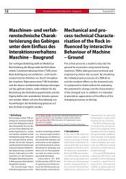
The cut-and-cover tunnel can<br />
be constructed as double-deck<br />
underground structure (similar<br />
to 2 levels underground basement)<br />
– please see attached<br />
illustration (Fig. 2).<br />
Not practical in every area considering<br />
current land use (e.g. Bangkok suburban<br />
and urban land use). Expensive to<br />
appropriate the land owned by ordinary<br />
citizens or private sectors<br />
Practical to implement but relatively<br />
ineffective due to limited flood drain<br />
capacity<br />
Practical and effective in most areas and<br />
land use especially in Bangkok<br />
Upper Deck – will be used as<br />
road tunnel in normal condition,<br />
no flood or minor flood as<br />
shown in Fig. 3 and during moderate<br />
flood Fig. 4.<br />
Lower Deck – will be used as<br />
flood drain in normal condition,<br />
no flood or minor flood as shown<br />
in Fig. 3 and during moderate<br />
flood Fig. 4.<br />
Upper Deck – will be stopped<br />
using as road tunnel or underground<br />
motorway and will be<br />
used as flood drain or flood way<br />
once major flood comes.
<strong>Tunnel</strong> 3/2012<br />
Total length of this underground<br />
system is approx.100 km depending<br />
on the final selection based<br />
on further feasibility studies.<br />
In some difficult area where<br />
cut-and-cover tunnel is not applicable,<br />
bored tunnels using<br />
TBM may be used to construct<br />
the underground flood drain<br />
tunnels.<br />
MUSTS integrated with<br />
other Systems<br />
Multi-Service Flood <strong>Tunnel</strong> System<br />
(MUSTS) will be integrated<br />
with Type 1 and Type 2 as<br />
appropriate in both provinces<br />
in urban area of Bangkok. In<br />
Bangkok, in addition to existing<br />
Type 1 system, large to medium<br />
diameter (3 to 5 m) inlet flood<br />
tunnels will be constructed to<br />
drain the runoff water from critical<br />
flood prone area into MUST<br />
during rainy season and during<br />
storm or flash flood – please see<br />
Fig. 5.<br />
Multi-Service Flood <strong>Tunnel</strong> System<br />
Possible Power Generation<br />
using Deep Shaft<br />
integrated with MUSTS<br />
Drained water from MUSTS can<br />
be further utilized to produce<br />
hydro-power as can be seen in<br />
attached sketch (Fig. 6 ).<br />
Depending on the selected<br />
size of the project, electricity of<br />
400 to 600 MW can be produced<br />
by extended application of<br />
MUSTS as Multipurpose Underground<br />
System.<br />
Key Advantages of<br />
MUSTS<br />
Large volume of floodwater can<br />
be drained out in a short time due<br />
to high hydraulic gradient (1,500<br />
m 3 /s, 129,600,000 m 3 /day).<br />
Minimum land appropriation<br />
is required – practical for existing<br />
land use in Bangkok and nearby<br />
provinces.<br />
Can be integrated with existing<br />
drainage system to enhance<br />
flow rate in existing system.<br />
Normal or Minor Flood Situation (upper deck using as motorway, lower deck<br />
draining out<br />
Major Flood Situation (both upper and lower decks using as flood drain tunnel)<br />
Multipurpose Underground Service Flood <strong>Tunnel</strong> System (MUSTS)<br />
Minimum land appropriation is<br />
required – practical for existing<br />
land use in Bangkok and nearby<br />
provinces.<br />
Can be applied as multi-service<br />
system for maximum benefits<br />
for the public.<br />
3 4<br />
Moderate Flood Situation (upper deck using as motorway, lower deck draining<br />
out water)<br />
5 6<br />
Power Generation Shaft in Multi-Service Flood <strong>Tunnel</strong> System<br />
17<br />
2
18 ITA-COSUF <strong>Tunnel</strong> 3/2012<br />
ITA-COSUF: The Operation of Safe<br />
and Secure Underground Facilities<br />
During the last decades, operational safety of underground structures<br />
has received increased public attention mainly after the disastrous fires in<br />
alpine road tunnels, fires in the Channel <strong>Tunnel</strong> as well as metro fires. The<br />
following article shows, what ITA-COSUF – the ITA Committee on Operational<br />
Safety of Underground Facilities - means.<br />
Götz Vollmann, Member of the Steering Board of ITA-COSUF, Institute for <strong>Tunnel</strong>ling and Construction Management,<br />
Ruhr-University Bochum/D<br />
Roland Leucker, Member of the Steering Board of ITA-COSUF, Managing Director of STUVA, Research Association for<br />
Underground Transportation Facilities, Cologne/D<br />
Dirk K. Sprakel, Member of the Steering Board of ITA-COSUF, Managing Director, FOGTE Fire Protection, Cologne/D<br />
1 Introduction<br />
During the last decades, operational<br />
safety of underground<br />
structures has received increased<br />
public attention mainly after the<br />
disastrous fires in alpine road tunnels,<br />
fires in the Channel <strong>Tunnel</strong><br />
as well as metro fires. Although<br />
operational safety always had<br />
been an important element in the<br />
design and construction of underground<br />
facilities it turned out to<br />
be a far more complex issue than<br />
anticipated before. The increase<br />
in traffic volume, especially regarding<br />
the transportation of heavy<br />
and dangerous goods, the age of<br />
certain infrastructures which need<br />
maintenance and/or considerable<br />
improvement in their safety installations<br />
after 20 years or even more<br />
in operation, the increasing complexity<br />
of underground infrastructures<br />
(complex underground road<br />
systems especially in urban areas<br />
with access and exit ramps, underground<br />
traffic circles and parking<br />
lots, longer and deeper tunnels<br />
for railway systems and deeper<br />
metro lines in combination with<br />
other urban infrastructures such<br />
as shopping malls, cinemas etc)<br />
– it all has severely increased the<br />
need for a holistic approach to the<br />
relevant safety issues.<br />
ration of underground facilities<br />
requires considering safety as<br />
well as security issues in a more<br />
and more holistic, comprehensive<br />
and decisive way.<br />
It also became apparent that an<br />
holistic safety approach needs<br />
to start at the very early phases<br />
of the design and that it is afterwards<br />
a constant issue in all<br />
further design and construction<br />
phases. All corresponding operational<br />
aspects and the stakeholders<br />
involved occur and appear<br />
solely during the operational<br />
phase of the infrastructure, especially<br />
in case of an emergency.<br />
Regardless of the type of tunnel,<br />
the empowerment of its user<br />
to self rescue has to be considered<br />
as the dominating factor<br />
regarding the amount of possible<br />
risks, especially in terms of<br />
tunnel users and possible harm<br />
due to fire, smoke etc. Efficient<br />
concepts for safety-operation<br />
and corresponding technical<br />
measures are crucial.<br />
Nowadays operating authorities<br />
need to consider securing<br />
societal assets, leading directly<br />
to assessments regarding the<br />
impact of a single incident on a<br />
traffic network as a whole and its<br />
robustness and resilience. These<br />
scenarios may be induced by<br />
changes in climatic conditions,<br />
accidents with dangerous goods<br />
or criminal actions and asymmetric<br />
threats. Dealing with the ope- Logo of ITA-COSUF<br />
2 Why COSUF?<br />
The research projects and study<br />
groups funded by the European<br />
Union, following the aforementioned<br />
tunnel fires, enabled<br />
constituting a multidisciplinary<br />
network of experts working at<br />
universities, consulting firms,<br />
corporations and public service<br />
bodies throughout Europe. Many<br />
of these experts were motivated<br />
to establish a long-lasting cooperative<br />
framework in order to<br />
shape a comprehensive view<br />
of all tunnel safety<br />
and security aspects.<br />
1<br />
Upon consultation with PIARC,<br />
the foundation of a committee<br />
associated with ITA-AITES<br />
(International <strong>Tunnel</strong>ling and<br />
Underground Space Association)<br />
encompassing all types of<br />
underground facilities became<br />
a primary target. As a result, the<br />
Committee on Operational Safety<br />
of Underground Facilities<br />
(COSUF, Fig. 1) was created by<br />
ITA-AITES in May 2005. Since<br />
2011, Didier Lacroix (France) is<br />
presiding over COSUF. Current<br />
members of COSUF are involved<br />
in some of the most integral national<br />
and international Research<br />
and Development projects within<br />
the EU regarding safety and<br />
security, such as METRO, SOLIT²<br />
or SKRIBTPlus.<br />
COSF is open to any entity<br />
that develops an interest in<br />
the Committee‘s work and that<br />
would like to participate in its<br />
activities. In March 2012 the<br />
Committee membership stood<br />
at 72, a third of which are public<br />
bodies and training organizations<br />
and the remaining twothirds<br />
stem from the private<br />
sector. Currently 22 countries<br />
from Asia, Australia and Europe<br />
are represented.<br />
COSUF‘s objectives consist<br />
of: developing a forum for<br />
knowledge exchange; facilitating<br />
cooperative actions and<br />
international R&D initiatives;<br />
and promoting safety and security<br />
through innovation and<br />
acknowledgment of both current<br />
and future trends regarding<br />
all types of underground structures.<br />
The COSUF mission relies<br />
on the work of activity groups<br />
(AG), with the 4 most active ones<br />
described below.<br />
3 Activities within<br />
COSUF<br />
To facilitate the work on the<br />
special topics of interest regar-
<strong>Tunnel</strong> 3/2012<br />
ding COSUF 4 so-called activity<br />
groups were formed, reflecting<br />
the specific approaches in terms<br />
of the underlying fields of expertise.<br />
All Members of COSUF<br />
can freely choose to take part<br />
in any of these groups, with AG<br />
4 being the sole exception due<br />
to its narrowed field of application.<br />
In addition to typical group<br />
work the AG-members may be<br />
asked to help the steering board<br />
of COSUF in preparation of CO-<br />
SUF-related activities, such as<br />
internal or external workshops.<br />
These activities will be described<br />
in the following.<br />
3.1 Activity Group 1: Interaction<br />
with European and<br />
International Initiatives<br />
AG 1 is currently headed by Ben<br />
van den Horn (NL) and takes and<br />
keeps contact with other external<br />
institutions, groups and projects<br />
in order to receive relevant<br />
information, to co-operate for<br />
avoiding duplication of activities,<br />
to give information about<br />
activities in COSUF to external<br />
groups and possibly influence<br />
the initiatives.<br />
The activities in Activity Group<br />
1 consist e.g. of identifying and<br />
Safe and Secure Underground Facilities<br />
liaise with relevant initiatives<br />
outside COSUF, attracting COSUF<br />
members from these initiatives<br />
or appoint liaison responsible<br />
COSUF members, influencing<br />
initiatives to include safety and<br />
security aspects in line with the<br />
ideas of COSUF or bringing CO-<br />
SUF ideas to life as projects either<br />
as part of existing initiatives or as<br />
new separate projects.<br />
3.2 Activity Group 2: Regulations<br />
and Best Practice<br />
AG 2 is currently led by Peter<br />
Reinke (CH) and Stig Ravn (GB).<br />
It covers regulations, the stateof-the-art<br />
and best-practices in<br />
various countries. This includes<br />
discussion and comparison of<br />
regulations and best-practice<br />
procedures from different owners,<br />
networks, projects and the<br />
experience gained by them.<br />
By doing this it is aimed to<br />
collect and distribute information<br />
on existing national and<br />
international regulations and<br />
recognized recommendations<br />
as well as to establish the bestpractice<br />
recommendations for<br />
tunnel safety (and security). The<br />
findings can result in requirements<br />
for new regulations.<br />
AG 2 addresses the following<br />
topics at the moment:<br />
• Engineering guidance for<br />
scenarios and functional objectives<br />
for the design of fire<br />
safety of urban underground<br />
rail systems<br />
• Engineering guidance and<br />
best-practice recommendations<br />
regarding man-machine-interface<br />
of SCADA systems<br />
for tunnels<br />
• Best-practice recommendations<br />
for design of safety<br />
measures in road tunnels<br />
regarding implementation<br />
of EU directive on non-discrimination<br />
of disabled people<br />
• Engineering guidance for fire<br />
protection of platform screen<br />
doors of underground rail<br />
systems<br />
The area of security may be<br />
highlighted as well, since there<br />
is a need for establishing the<br />
state-of-the-art also in this field<br />
and has not taken place to any<br />
extent up to now. Security deviates<br />
from safety particularly with<br />
respect to the prevention, whereas<br />
the reaction consequence<br />
side may be similar to those<br />
which are resulting from evalu-<br />
SOLIT 2<br />
ation and analysis of accidents<br />
or so.<br />
3.3 Activity Group 3: Research<br />
and new findings<br />
The scope of AG 3, which is currently<br />
led by Götz Vollmann (D),<br />
is to motivate research and to<br />
use research results and other<br />
new findings for the benefit of<br />
safety and security in underground<br />
facilities in general.<br />
The activities include collection<br />
of results of research and<br />
new findings, the evaluation of<br />
events, results and new findings<br />
as well as the dissemination of<br />
the results and new findings<br />
among COSUF members. Additionally<br />
the group tries to collect<br />
and evaluate ideas for research<br />
and identify corresponding<br />
needs for the future and give<br />
directions for future research.<br />
The actual launch of new research<br />
projects is initiated outside<br />
the COSUF frame but can<br />
certainly be facilitated through<br />
the activities of COSUF and the<br />
AG. Therefore AG 3 can also<br />
be considered as the starting<br />
point for national as well as international<br />
R&D-projects such<br />
as SOLIT². In a broader sense<br />
19
2<br />
20 ITA-COSUF <strong>Tunnel</strong> 3/2012<br />
Activity Group 3 „Research and New Findings“ deals with latest<br />
results of safety and security related research (here: fire tests<br />
conducted within SOLIT2-project in 2011)<br />
the group’s aim is to make aware<br />
all relevant professionals of new<br />
findings and recent results of<br />
research in safety and security<br />
related activities regarding underground<br />
facilities, to discuss<br />
these results and other ideas and<br />
to process them into specifications<br />
of needs of new research<br />
into recommended best practices.<br />
Additionally the partners try<br />
to facilitate recommendations<br />
on specific topics which then will<br />
represent the opinion of some of<br />
the world’s leading experts. For<br />
instance, the group is currently<br />
working on a recommendation<br />
regarding computational fluid<br />
dynamics (CFD) simulations as<br />
an elementary input for quantitative<br />
risk assessments of road<br />
tunnels (Fig. 2).<br />
3.4 Activity Group 4: European<br />
Road <strong>Tunnel</strong> Safety<br />
Officers Forum<br />
ITA-COSUF pays special attention<br />
to road tunnel safety within the<br />
framework of Directive 2004/54/<br />
EC of 29 April 2004 on minimum<br />
safety requirements for tunnels<br />
in the trans-European road network.<br />
At November 4 to 5, 2009 in<br />
Lyon, ITA COSUF organized the<br />
1st European Forum of Road<br />
<strong>Tunnel</strong> Safety Officers, an event<br />
which was co-organized by<br />
CETU, ITA-COSUF, PIARC and the<br />
European Commission. Forty-five<br />
Safety Officers from 18 member<br />
states participated to exchange<br />
information, evaluate first operational<br />
experiences and compare<br />
role and duty interpretation of<br />
the Safety Officers.<br />
After this first event ITA-CO-<br />
SUF created the AG 4 within<br />
ITA-COSUF, the so-called <strong>Tunnel</strong><br />
Safety Officers (TSO) activity<br />
group, being further led by Alain<br />
Picard (France). By doing so, the<br />
ITA-COSUF acknowledges that<br />
most of the functions and tasks<br />
assigned to the Safety Officers<br />
by the EU <strong>Tunnel</strong> Directive can<br />
only be achieved by a qualitative<br />
approach, making exchanges<br />
between Safety Officers of paramount<br />
importance and that<br />
this is entirely part of ITA-COSUF’s<br />
scope and objectives.<br />
On the 18 th of January 2012<br />
again more than 40 tunnel safety<br />
officers from 18 European<br />
countries met in Brussels for<br />
taking part in the 2 nd European<br />
forum to find out how to make<br />
road tunnels safer across the European<br />
Union. Participants expressed<br />
their wish to continue<br />
and to strengthen this fruitful<br />
cooperation with the support of<br />
the European Commission. Johan<br />
Bosch (NL), who supported<br />
Alain Picard in the preparation<br />
of this event, will soon take over<br />
as the new leader of this activity<br />
group and thereby strengthen<br />
the international exchange of<br />
experiences.<br />
3.5 Additional workshops<br />
On a frequent basis COSUF prepares<br />
and conducts internal and<br />
external workshops, at least one<br />
of each per year. While all external<br />
workshops are open for public<br />
contribution, internal workshops<br />
are seen as a special service for<br />
the COSUF members in general<br />
and the AG members in specific.<br />
That said, external workshops<br />
will be held at a certain location<br />
with presentations of different<br />
specialists regarding one topic,<br />
such as the external workshop<br />
on Risk Analysis Techniques and<br />
Approaches which was held in<br />
Frankfurt in 2011.<br />
Internal workshops on the<br />
other hand are reserved only for<br />
COSUF-members. Therefore the<br />
steering board is looking to find<br />
excellent locations, where AGmeetings<br />
are easily combinable<br />
with site visits and additional<br />
presentations on the site itself<br />
and all site-related safety and<br />
security matters. That said, the<br />
steering board teamed up with<br />
more than 100 members of CO-<br />
SUF for our latest internal workshop<br />
in Amsterdam/Amersfoort<br />
(NL) where all participating<br />
members got to see the specific<br />
concepts regarding the<br />
Amsterdam North-South line.<br />
Thereby COSUF has served its<br />
members lots of valuable and<br />
interesting information in the<br />
course of more than 15 workshops<br />
throughout the last couple<br />
of years (Fig. 3).
<strong>Tunnel</strong> 3/2012<br />
4 Conclusion<br />
As revealed in the accomplishments<br />
described above, COSUF‘s<br />
years of operations have yielded<br />
very encouraging results. Beginning<br />
with former members of European<br />
research projects, COSUF‘s<br />
composition has gradually grown,<br />
in terms of skill sets and geographic<br />
coverage, yet the added railroad<br />
and subway modes still need<br />
to be further developed.<br />
COSUF has helped nurture<br />
synergy. Many methodological<br />
contributions specific to road<br />
tunnels stemming from PIARC<br />
and COSUF make it possible<br />
to overlap these contributions<br />
with problems raised by other<br />
types of underground facilities.<br />
Moreover, COSUF‘s research en-<br />
Safe and Secure Underground Facilities<br />
deavours and the presence of<br />
industry representatives on the<br />
Committee provide access to re-<br />
3<br />
search and innovation programs.<br />
The pursuit and expansion of<br />
COSUF activities, as the bene-<br />
The ITA-COSUF workshop 2011 in Helsinki “Designing Underground Safety – How far to go?” aroused great interest<br />
Wer richtig plant, bleibt trocken.<br />
Als Pioniere in der Abdichtungstechnik entwickeln wir Produkte für die höchsten,<br />
trockensten Ansprüche Ihrer <strong>Tunnel</strong>projekte – denn Trockenheit heisst<br />
auch Sicherheit! Problemorientierte und massgeschneiderte Abdichtungskonzepte<br />
sichern den Erfolg! RASCOR - Pioniere der Bauabdichtung.<br />
ficiary of cooperation between<br />
PIARC and ITA-AITES, thus merits<br />
strong encouragements.<br />
Rascor International AG<br />
Gewerbestrasse 4<br />
CH-8162 Steinmaur<br />
Telefon +41 (0)44 857 11 11<br />
Telefax +41 (0)44 857 11 00<br />
info@rascor.com<br />
21<br />
®
22 Malaysia Kuala Lumpur<br />
<strong>Tunnel</strong> 3/2012<br />
Wasserversorgungstunnel<br />
in Kuala Lumpur<br />
In den Bergen von Kuala Lumpur/Malaysia wird<br />
bei hoher Überdeckung der 44,6 km lange<br />
Pahang Selangor Wassertunnel mit 3 TBM von<br />
Robbins vorgetrieben. Mit diesem <strong>Tunnel</strong> soll<br />
die nachlassende Trinkwasserversorgung der<br />
Metropole durch Lieferung aus anderen Gebieten<br />
um Kuala Lumpur verbessert werden.<br />
Mit einer Länge von 44,6 km<br />
durch massives Felsgestein,<br />
heiße Mineralquellen und<br />
Verwerfungszonen zählt der<br />
Pahang-Selangor Raw Water<br />
<strong>Tunnel</strong> in Malaysia sicher nicht<br />
zu den einfachen Bauprojekten.<br />
Fachkräfte und Arbeiter aus Indonesien,<br />
Thailand, Japan, dem<br />
Vereinigten Königreich und Malaysia<br />
sind auf 3 TBM- und mehrere<br />
NÖT-Baustellen verteilt, wo<br />
sie in Schichtarbeit unermüdlich<br />
den <strong>Tunnel</strong> vorantreiben.<br />
Aufgrund der abgelegenen<br />
Baustellen, weit entfernt von<br />
der Hauptstadt Kuala Lumpur,<br />
müssen nicht nur Vorräte per<br />
Lkw herangeschafft werden.<br />
Notgedrungen müssen täglich<br />
<strong>Tunnel</strong>bauelemente wie Sohltübbinge<br />
vor Ort hergestellt<br />
Desiree Willis, Technical Writer, The Robbins Company, Kent, WA/USA<br />
www.TheRobbinsCompany.com<br />
werden. „Unsere TVM werden<br />
auf einer Länge von über 33 km<br />
in den unterschiedlichsten Gesteinsformationen<br />
eingesetzt.<br />
Während die TVM in einem <strong>Tunnel</strong><br />
auf eine Gesteinsfestigkeit<br />
von 230 MPa trifft, muss sich die<br />
TVM in einem anderen <strong>Tunnel</strong><br />
mit nur 50 MPa durch den Fels<br />
vorarbeiten. Unglaublich, aber<br />
diese TVM sind bisher mit allem<br />
fertig geworden – und wir liegen<br />
auch noch gut in der Zeit“,<br />
berichtete Andy Birch, Robbins‘<br />
Leiter der Baustelle Adit 4. Seit<br />
dem Frühjahr 2012 werden 3<br />
TVM mit einem Durchmesser<br />
von je 5,23 m eingesetzt, die<br />
durchschnittlich einen monat-<br />
Water <strong>Tunnel</strong> in Kuala<br />
Lumpur<br />
The 44.6 km long Pahang Selangor Water <strong>Tunnel</strong><br />
is utilizing 3 Main Beam TBMs from Robbins to<br />
excavate under complex, high cover conditions<br />
in the mountains outside of Kuala Lumpur/Malaysia.<br />
The tunnel will bolster dwindling supplies<br />
in the capital city by transferring water from<br />
other areas.<br />
At 44.6 km long below mountainous<br />
hard rock, hot springs, and<br />
fault zones, Malaysia’s Pahang<br />
Selangor Raw Water <strong>Tunnel</strong> is<br />
no easy excavation. A tireless<br />
workforce, hailing from Indonesia,<br />
Thailand, Japan, the U.K., and<br />
Malaysia are assigned to each of 3<br />
TBM sites as well as several NATM<br />
sites, where they work in shifts.<br />
Supplies are trucked in and components<br />
such as invert segments<br />
are cast daily on the TBM sites out<br />
of necessity due to the remote<br />
project locations outside of Kuala<br />
Lumpur. “We’ve got over 33 km of<br />
TBM excavation in really different<br />
rock conditions. We are going<br />
from 230 MPa rock strength in<br />
Pahang Selangor Map: A combination of several NATM headings and 3 TBM drives are being used to excavate the long tunnel<br />
one tunnel down to 50 MPa and<br />
blocky ground in another tunnel.<br />
These machines have been<br />
able to handle everything we’ve<br />
thrown at them, while maintaining<br />
good advance rates,” said<br />
Andy Birch, Robbins site manager<br />
at the Adit 4 site. As of Spring<br />
2012 three 5.23 m diameter TBMs<br />
were averaging 500 m per month<br />
with maximum rates as high as<br />
721 m. Their innovative means to<br />
achieve these rates ranges from<br />
custom muck removal to novel<br />
ground support to high-tech<br />
wireless data analysis.<br />
One of the Longest <strong>Tunnel</strong>s<br />
in Southeast Asia<br />
Kuala Lumpur, a city of 7.2 million<br />
people, is a former tin mining<br />
town ideally located in the bowlshaped<br />
Klang Valley surrounded<br />
by mountains. Now the most populous<br />
city in Malaysia, the water<br />
supply sourced from local rivers<br />
is projected to run short in the<br />
near future. To address forecasted<br />
needs, the Malaysian Ministry of<br />
Energy, Green Technology, and<br />
Water (KeTTHA) has commissioned<br />
the Pahang-Selangor Raw<br />
Water <strong>Tunnel</strong> – one of the longest<br />
tunnels in Southeast Asia.<br />
The conduit will transfer water<br />
from the Semantan River in Pahang<br />
State to the Selangor/Kuala<br />
Lumpur region, travelling as
<strong>Tunnel</strong> 3/2012<br />
lichen Vortrieb von 500 m – und<br />
bisher einen Maximalvortrieb<br />
von 721 m – geschafft haben.<br />
Zu den Innovationen, die diese<br />
Geschwindigkeiten ermöglicht<br />
haben, zählen neben der spezifischen<br />
Lösung für Schutterung<br />
auch neue Techniken<br />
zur Felssicherung sowie eine<br />
funkgestützte Datenanalyse<br />
der neuesten Generation.<br />
Einer der längsten <strong>Tunnel</strong><br />
in Südostasien<br />
Kuala Lumpur, wo heute 7,2<br />
Mio. Menschen leben, war<br />
ehemals eine Kleinstadt, die<br />
von Zinnabbau lebte. Sie liegt<br />
ideal in dem beckenförmigen<br />
und von Bergen umsäumten<br />
Klang Valley. In der bevölkerungsreichsten<br />
Stadt Malay-<br />
sias hat man erkannt, dass die<br />
bisher über die nahegelegenen<br />
Flüsse abgesicherte urbane<br />
Wasserversorgung in naher<br />
Zukunft an ihre Grenzen stoßen<br />
wird. Um den prognostizierten<br />
Wasserbedarf abzudecken, hat<br />
das malaysische Ministerium<br />
für Energie, Grüne Technologien<br />
und Wasser (KeTTHA)<br />
Wasserversorgungstunnel Water <strong>Tunnel</strong><br />
23<br />
At 44.6 km long, the Pahang Selangor Raw Water <strong>Tunnel</strong> is one of Southeast Asia’s longest<br />
das Projekt Pahang-Selangor<br />
Raw Water <strong>Tunnel</strong> – einen der<br />
längsten <strong>Tunnel</strong> Südostasiens<br />
– in Auftrag gegeben. Mit dieser<br />
Versorgungsleitung wird<br />
Flusswasser aus dem Bundesstaat<br />
Pahang in die Region<br />
Selangor/Kuala Lumpur transportiert,<br />
und zwar in einer Tiefe<br />
von bis zu 1200 m unter der<br />
Titiwangsa-Gebirgskette.<br />
Ab Mai 2014 sollen pro Sekunde<br />
bis zu 27,6 m 3 Rohwasser<br />
durch den fertig gestellten<br />
<strong>Tunnel</strong> fließen. Über eine 858<br />
m lange Einspeiseleitung mit<br />
Pumpstation im Becken des Pahang<br />
River wird dann Wasser<br />
in den <strong>Tunnel</strong> geleitet, das in<br />
Selangor entnommen und zu<br />
einer neuen Wasseraufbereitungsanlageweitertransportiert<br />
wird.<br />
Mit Blick auf einen zügigen<br />
Vortrieb durch schwierige<br />
Geologie und Bereiche hoher<br />
Überdeckung entwickelte das<br />
KeTTHA ein Projekt, das mehrere<br />
<strong>Tunnel</strong>vortriebe mit dem<br />
NÖT-Ausbaukonzept an den<br />
Anfangs- und Endpunkten<br />
kombiniert. Nach einer sorg-<br />
deep as 1,200 m beneath the<br />
Titiwangsa mountain range.<br />
Up to 27.6 m 3 of raw water<br />
per second is scheduled to begin<br />
flowing through the completed<br />
tunnel by May 2014. An 858 m<br />
long inlet conduit structure and<br />
pumping station, located in the<br />
Pahang River Basin, will draw water<br />
from the river to the tunnel,<br />
while outlet structures in Selangor<br />
will transfer the water to the<br />
site of a new treatment plant. In<br />
order to excavate swiftly in difficult<br />
high cover rock conditions,<br />
KeTTHA developed a program<br />
combining multiple TBM drives<br />
with NATM methods at the inlet<br />
and outlet portals. After a detailed<br />
prequalification and bid<br />
process, SNUI JV was selected<br />
in 2009 as the contractor for the<br />
project - a consortium of Shimizu<br />
Corporation and Nishimatsu<br />
Construction of Japan, along<br />
with local companies IJM Corp.<br />
and UEM Builders Bhd. The JV is<br />
now operating 3 Robbins Main<br />
Beam TBMs, each excavating tunnel<br />
sections ranging from 11.3 to<br />
11.8 km in length, in mountainous<br />
areas outside the city.<br />
<strong>Tunnel</strong>ling Methods<br />
While vertical tunnel walls were<br />
specified in short sections of<br />
NATM excavation (ranging<br />
from 1.9 to 2.6 km each), the<br />
tunnel length and geology,<br />
consisting of granites with approx.<br />
50 to 200 MPa UCS, prevented<br />
using drill and blast for<br />
the main drive. “In this type of<br />
hard rock, we prefer to use Robbins<br />
TBMs. The total contract<br />
construction time is 5 years and<br />
the tunnel is quite long, so drill<br />
and blast could not have done<br />
this in the time specified,” said<br />
Ohashi, Mechanical Engineer<br />
for SNUI JV.<br />
The contractor’s experience<br />
with Robbins TBMs also helped<br />
them to narrow down a decision.<br />
“When I worked in Hong<br />
Kong in 1998, I used a TBM of<br />
this manufacturer on a tunneling<br />
project, so this is my<br />
second time using a Robbins<br />
machine. I have used other<br />
machines, but this design is<br />
simpler and easier to use, and<br />
more powerful,” said Nakano,<br />
Deputy Project Manager for the<br />
SNUI JV.
24 Malaysia<br />
Kuala Lumpur <strong>Tunnel</strong> 3/2012<br />
Three 5.23 m diameter Main Beam<br />
TBMs are excavating up to 721 m<br />
per month in Malaysia<br />
fältigen Vorauswahl und Ausschreibung<br />
wurde 2009 der<br />
SNUI JV – einem Konsortium<br />
aus den japanischen Firmen<br />
Shimizu Corporation und Nishimatsu<br />
Construction sowie den<br />
lokalen Unternehmen IJM Corp.<br />
und UEM Builders Bhd. – der<br />
Zuschlag erteilt. Das Joint Venture<br />
setzt heute 3 offene Robbins-TVM<br />
ein, um 11,3 bis 11,8<br />
km lange <strong>Tunnel</strong>abschnitte aus<br />
den Bergen vor den Toren der<br />
Stadt zu fräsen.<br />
Angewandte Vortriebstechniken<br />
Auch wenn in manchen kürzeren<br />
Abschnitten (zwischen 1,9<br />
und 2,6 km) nach der NÖT-Me-<br />
thode gearbeitet werden kann,<br />
so lassen die <strong>Tunnel</strong>länge und<br />
die Geologie – Granit mit einer<br />
Druckfestigkeit zwischen 50<br />
und 200 MPa – die Bohr- und<br />
Sprengvortriebsmethode als<br />
primäre Ausbautechnik nicht zu.<br />
„Bei solch festem Gestein setzen<br />
wir lieber die TVM ein. Laut Vertrag<br />
ist der <strong>Tunnel</strong> in 5 Jahren<br />
fertig zu stellen. Angesichts der<br />
<strong>Tunnel</strong>länge wäre mit der Bohr-<br />
und Sprengvortriebstechnik<br />
diese Vorgabe nicht einzuhalten“,<br />
sagte Maschinenbauingenieur<br />
Ohashi vom SNUI JV.<br />
Die Erfahrung des Baukonsortiums<br />
mit den TVM war ein<br />
weiterer Faktor bei der Entscheidungsfindung.<br />
„Als ich<br />
Hard Rock Machines,<br />
High-Tech Design<br />
To tackle the high cover, hard<br />
rock conditions, the 3 machines<br />
were designed with unique<br />
design aspects - from custom<br />
cutterheads to streamlined<br />
operator’s cabs. The TBMs were<br />
engineered with the smallest diameter<br />
back-loading cutterheads<br />
ever to be mounted with 19-inch<br />
disc cutters. The back-loading<br />
design increases safety and efficiency<br />
during cutter changes,<br />
as workers are not exposed to<br />
the tunnel face. The larger cutter<br />
diameter also aids in increased<br />
cutter life and higher advance<br />
rates in hard rock, compared to<br />
17-inch diameter cutters.<br />
Cutter Monitoring<br />
Not only is the cutterhead design<br />
novel, but the cutters themselves<br />
are being continuously<br />
analyzed using Robbins’ new<br />
cutter monitoring system. The<br />
wireless system keeps track of<br />
several variables on each cutter,<br />
including cutter rotation, temperature,<br />
and vibration.<br />
Following some design modifications,<br />
the monitors have<br />
been installed on the 19-inch<br />
face and gage cutters of 1 of the<br />
3 TBMs, with installations planned<br />
on the other 2 TBMs shortly.<br />
Each cutter is equipped with a<br />
sensor bolted inside the cutter<br />
housing, allowing raw data to<br />
be sent to a program display in
<strong>Tunnel</strong> 3/2012<br />
1998 in Hongkong gearbeitet<br />
habe, habe ich bei einem <strong>Tunnel</strong>projekt<br />
eine Robbins-TVM<br />
eingesetzt. Das ist also das<br />
zweite Mal, dass ich mit einer<br />
TVM dieses Herstellers zu tun<br />
habe. Natürlich habe ich schon<br />
andere TVM eingesetzt, aber<br />
Robbins hat da eine Maschine,<br />
die einfacher und leichter zu<br />
bedienen und leistungsstärker<br />
ist“, so Nakano, stellvertretender<br />
Projektleiter der SNUI JV.<br />
High-Tech-TVM für<br />
Festgestein<br />
Um das hohe, feste Deckgestein<br />
abzutragen, haben die<br />
Konstrukteure besondere Lösungen<br />
für die 3 TVM umgesetzt:<br />
von maßgeschneiderten<br />
Bohrköpfen bis hin zu einsatz-<br />
optimierten Führerkabinen.<br />
Die Backloading-Bohrköpfe<br />
weisen den kleinsten Durchmesser<br />
auf, der jemals mit 19“-<br />
Schneidrollen realisiert wurde.<br />
Das Backloading-Design<br />
erhöht zudem die Sicherheit<br />
und Effizienz beim Meißelaustausch,<br />
da somit die Arbeiter<br />
nicht mit der Ortsbrust in<br />
Wasserversorgungstunnel Water <strong>Tunnel</strong><br />
25<br />
Kontakt kommen. Der größere<br />
Meißeldurchmesser erhöht<br />
die Lebensdauer und<br />
ermöglicht im Vergleich zu<br />
einem 17“-Meißel eine höhere<br />
Vortriebsgeschwindigkeit in<br />
Festgestein.<br />
Überwachung des<br />
Bohrkopfs/der Rollenmeißel<br />
Nicht nur der Bohrkopf wurde<br />
neu konzipiert, auch die<br />
Meißel selbst werden ständig<br />
über das neue hauseigene<br />
Meißelüberwachungssystem<br />
überprüft. Mit dem drahtlosen<br />
Überwachungssystem werden<br />
verschiedene Betriebsparameter<br />
der Meißel kontinuierlich<br />
überwacht, u.a. ihre Drehgeschwindigkeit,<br />
Temperatur und<br />
die Vibrationsstärke.<br />
Nach Durchführung einiger<br />
konstruktionsbedingter Änderungen<br />
wurden die Sensoren<br />
an der Stirnseite der 19“-Rollenmeißel<br />
einer der 3 TVM angebracht.<br />
Die beiden anderen<br />
TVM sollen damit ebenfalls<br />
bestückt werden. In jedem<br />
Meißelgehäuse befindet sich<br />
Wireless operator’s cabs and touch screens in each TBM enable user-friendly<br />
tracking of all the machine’s functions<br />
the operator’s cabin. “The new<br />
system allows contractors to<br />
plan cutter changes, because<br />
they know when one cutter<br />
becomes blocked and stops<br />
rotating, creating a higher load<br />
on the adjacent state of wear<br />
of all their cutters. They are also<br />
aware of sudden cutter failures<br />
through increases in temperature<br />
or failed rotation,” said<br />
Steve Smading, Cutter Product<br />
Manager.<br />
Touch Screens and<br />
Wireless Operation<br />
Operator’s cabs on each of the 3<br />
machines include industrial computer<br />
systems and wireless routers.<br />
The routers allow for laptop<br />
access to control systems from<br />
any location on the TBM, and<br />
allow for remote access of the<br />
Programmable Logic Controller<br />
(PLC). Integrated touch screens<br />
are another feature of the cab<br />
designs. Dual Central Proces-
26 Malaysia<br />
Kuala Lumpur <strong>Tunnel</strong> 3/2012<br />
ein Sensor, der Rohdaten an<br />
eine Anzeige im Führerhaus<br />
weiterleitet.<br />
„Unser neues System bietet<br />
nun die Möglichkeit, die<br />
Meißel dann auszutauschen,<br />
wenn es vonnöten ist. Man<br />
weiß nun, wann ein Meißel<br />
blockiert ist und sich nicht<br />
mehr dreht, was zu einer höheren<br />
Belastung und einem<br />
höheren Verschleiß der üb-<br />
Prozessoren ermöglichen die<br />
Steuerung eines TVM-Betriebs-<br />
und TVM-Notfallsystems. Auf die<br />
Videoüberwachungsanlagen<br />
(CCTV), automatische Messdatenerfassungs-<br />
und lasergestützte<br />
Führungssysteme kann über<br />
die Touchscreens, die eine individuelle<br />
Anpassung erlauben, problemlos<br />
zugegriffen werden.<br />
Dank Systemintegration und<br />
Ethernet-Anschluss können alle<br />
Remote adit sites are located in the mountains surrounding Kuala Lumpur,<br />
Malaysia, requiring supplies such as invert segments to be cast onsite<br />
rigen Meißel führen würde.<br />
Auch plötzliche Meißelausfälle<br />
werden dem Maschinisten<br />
durch eine steigende Meißeltemperatur<br />
oder eine auf Null<br />
zurückgegangene Rotationsgeschwindigkeit<br />
angezeigt“,<br />
so Steve Smading, Cutter Product<br />
Manager.<br />
Touchscreens und<br />
drahtloser Maschinenbetrieb<br />
Die Führerstände aller 3 TVM<br />
wurden mit Industriecomputern<br />
und drahtlosen Routern<br />
ausgestattet. Über Letztere<br />
kann per Laptop von jedem<br />
Standpunkt aus Zugriff auf<br />
die Steuerung der TVM genommen<br />
werden. Fernzugriff<br />
über den Programmable Logic<br />
Controller (PLC) ist ebenso<br />
möglich. Zu den Neuerungen<br />
im Führerhaus zählen auch<br />
Touchscreens. Computer mit 2<br />
Daten per Glasfaserkabel zur<br />
Oberfläche zur weiteren Analyse<br />
übertragen werden. „Wir<br />
speichern alle Echtzeitdaten<br />
auf Servern. Diese stehen in<br />
den Baustellenbüros. Zusätzlich<br />
steht noch einer in Tokyo. Von<br />
dort werden die Daten für einen<br />
Zugriff per Internet zur Verfügung<br />
gestellt. So können Informationen<br />
über den aktuellen<br />
Projektstand überall auf der Welt<br />
von einer passwortgeschützten<br />
Website abgerufen werden“, so<br />
Nakano.<br />
Neuartige Erdreichabstützung<br />
Zwar reicht die Palette für die<br />
Gesteinsart abhängige Felssicherung<br />
von Stahlbügeln bis<br />
hin zu Ankerbolzen, die Abstützung<br />
erfolgt jedoch primär mit<br />
einem neuartigen Spritzbeton.<br />
Dieser – eine Mischung aus<br />
einem Spezialtrockenmörtel,<br />
sing Units (CPUs) provide both<br />
an operating and standby system<br />
for machine control, while<br />
Closed-Circuit Television (CCTV),<br />
data logging, and laser guidance<br />
systems are all accessible and adjustable<br />
via the screens.<br />
Due to the system integration<br />
and ethernet connection, all data<br />
can be transmitted to the surface<br />
via fiber optic cables for viewing.<br />
“We have been keeping all real-<br />
Three continuous conveyor systems are<br />
operating simultaneously behind each TBM,<br />
averaging 92 % availability<br />
time data on our servers. These<br />
are in our site offices, and there is<br />
one in Tokyo, which then routes<br />
the data on the internet. Because<br />
of this our actual progress data is<br />
available anywhere in the world<br />
from our password-protected<br />
website,” said Nakano.<br />
Novel Ground Support<br />
While the ground support program<br />
varies from steel straps to
<strong>Tunnel</strong> 3/2012<br />
Polypropylenfasern und einem<br />
Schnellbinder – wird manuell<br />
über eine kontinuierlich betriebene<br />
Pumpanlage (Mischen<br />
und Befüllen) aufgetragen. Der<br />
von den japanischen Firmen<br />
MCM Co., Ltd. und DENKA entwickelte<br />
Beton wurde schon bei<br />
vielen TVM- und NÖT-Projekten<br />
in Japan eingesetzt. Erstmals<br />
wird er nun bei einem internationalen<br />
Vorhaben verwendet.<br />
Wasserversorgungstunnel Water <strong>Tunnel</strong><br />
27<br />
„Die Trockenmischanlage bietet<br />
den Vorteil, dass man sie nach<br />
Bedarf ein- und ausschalten<br />
kann. Sie kann sogar im TVM-<br />
Nachläufer mitgeführt werden.<br />
Im Vergleich dazu verursachen<br />
Nassmischanlagen Materialverluste,<br />
wenn sie ständig ein- und<br />
ausgeschaltet werden, was zu<br />
reinigungsbedingten Standzeiten<br />
führt“, so Nobuo Suematsu<br />
von MCM Co., Ltd.<br />
rock bolts based on the rock<br />
classification, the majority of<br />
primary support is being done<br />
using a novel type of shotcrete.<br />
The shotcrete is applied manually<br />
and consists of a continuous<br />
mixing and charging pump<br />
system, customized dry mortar<br />
mix with polypropylene fibers,<br />
and a fast-acting accelerator.<br />
The shotcrete, developed by<br />
MCM Co., Ltd. and DENKA of<br />
Japan, has been used on numerous<br />
TBM and NATM projects<br />
in Japan, though this is<br />
the first time the system has<br />
been used internationally. “The<br />
dry mix system is advantageous<br />
because it can be started and<br />
stopped whenever necessary,<br />
and can be mounted in the<br />
TBM back-up. Wet systems, by<br />
comparison, generate unused<br />
mortar if frequently started and
28 Malaysia<br />
Kuala Lumpur <strong>Tunnel</strong> 3/2012<br />
A novel type of polypropylene fi ber shotcrete is being applied as the primary means of ground support - a mixture that<br />
reduces rebound<br />
Die Firmen MCM und DENKA<br />
haben mit Robbins kooperiert,<br />
um einen Spritzbeton zu entwickeln,<br />
der praktisch nicht quillt<br />
und der als primäre Erdreichabstützung<br />
dienen soll. Der Beton<br />
wird nach jedem TVM-Takt in<br />
einer Schicht von 2 cm direkt<br />
hinter der Bohrkopfabstützung<br />
aufgebracht und abhängig vom<br />
Erdreich mit einem Ringanker<br />
verstärkt. 24 Stunden nach seiner<br />
Auftragung weist der Beton<br />
eine Druckfestigkeit von bis zu<br />
15 MPa auf. „Der Beton ist sehr<br />
schnell bindend und breitet<br />
sich nicht aus – das alles, ohne<br />
dass der Mörtel einem hohen<br />
Druck ausgesetzt werden<br />
muss“, so Nakano.<br />
Förderbänder im Dauerbetrieb<br />
Drei kontinuierlich betriebene<br />
Textilförderbänder von Robbins<br />
werden gleichzeitig hinter<br />
den TVM betrieben. Laut<br />
Nakano war dies die einzige<br />
Lösung, um maximale Effi zienz<br />
zu erreichen: „Ganz zu Anfang<br />
haben wir an Loren oder Karren<br />
mit Vollgummireifen für die<br />
Schutterung gedacht, aber der<br />
<strong>Tunnel</strong>durchmesser ist zu klein<br />
dafür, außerdem hätten Loren<br />
zu viel Zeit gekostet. Eine doppelte<br />
Gleisführung war wegen<br />
des zu kleinen Durchmessers<br />
auch ausgeschlossen. Also blieben<br />
nur noch Förderbänder. Die<br />
Zeit für den Ausbau der Förderbänder<br />
ist sehr kurz, was wiederum<br />
von großem Vorteil für uns<br />
ist“. Die Förderanlage wird derzeit<br />
alle 8 bis 10 Tage erweitert,<br />
der Zeitaufwand hierfür liegt bei<br />
10 bis 12 Stunden. In dieser Zeit<br />
können auch Wartungsarbeiten<br />
an der TVM durchgeführt und<br />
die Meißel inspiziert werden.<br />
Bei Erstellung dieses Beitrags<br />
wies die Förderanlage<br />
eine Verfügbarkeitsquote von<br />
durchschnittlich 92 % auf, d.h.<br />
problematische Fördersituationen<br />
sind selten. „Wir sind mit<br />
Adit 4 Site Manager Andy Birch (Robbins) surveys the excavated tunnel<br />
stopped, requiring downtime for<br />
cleaning,” said Nobuo Suematsu,<br />
MCM Co., Ltd.<br />
MCM and DENKA worked<br />
with Robbins to create a nearzero<br />
rebound L1 shotcrete system<br />
to be used as the primary<br />
means of ground support. The<br />
shotcrete is applied following<br />
each TBM stroke in a 2 cm layer<br />
directly behind the cutterhead<br />
support, and is accompanied by<br />
ring beams depending on the<br />
ground conditions. Compres-<br />
sive strength of up to 15 MPa is<br />
achieved within 24 hours of application.<br />
“The shotcrete is very<br />
quick setting with no rebound,<br />
and the mortar does not require<br />
high pressure application,” said<br />
Nakano.<br />
Continuous Conveyors<br />
Three Robbins fabric belt continuous<br />
conveyors are operating<br />
simultaneously behind the TBMs,<br />
a setup that was the only way<br />
to maximize effi ciency, according<br />
to Nakano: “We considered<br />
muck cars and rubber-tired<br />
trucks early on, but the tunnel<br />
diameter is too small for trucks,<br />
and muck cars would take too<br />
much time out of the schedule.<br />
This is because the diameter<br />
is so small; we couldn’t make a<br />
double track. Conveyor was our<br />
only choice. The extension time<br />
for the conveyor is very short,<br />
so this is a big advantage for<br />
us.” The belt is added every 8 to<br />
10 days, a process that takes 10<br />
to 12 hours and is paired with<br />
TBM maintenance and cutter<br />
inspections.<br />
At the time of writing the<br />
conveyors were operating with<br />
good availability, averaging at<br />
92 % with few problems. “We<br />
like the continuous conveyor<br />
because we can bore without<br />
interruptions, so we can make
<strong>Tunnel</strong> 3/2012<br />
den ständig laufenden Bändern<br />
sehr zufrieden, weil wir ohne<br />
Unterbrechung bohren können.“,<br />
so Chefi ngenieur Mito von<br />
der Shimizu Corporation auf der<br />
Baustelle Adit 4.<br />
Weit auseinanderliegende<br />
Baustellen Adit<br />
2 bis 4<br />
Die 3 TVM wurden in Shanghai<br />
zusammengebaut und nach<br />
Port Klang verschiff t, wo sie per<br />
Lkw zu den Baustellen transportiert<br />
wurden. Die abgelegenste<br />
Baustelle – Adit 2 genannt – liegt<br />
hoch oben in den dicht bewaldeten<br />
Hängen bei Karak, ca. 45<br />
km von Kuala Lumpur entfernt.<br />
Die auf der entlegenen Baustelle<br />
tätigen Arbeiter berichten,<br />
dass sie schon Kobras, Aff en<br />
und gelegentlich auch Tiger<br />
gesehen hätten. Die komplette<br />
Versorgung der Baustelle, einschließlich<br />
des Materials für die<br />
einzubauenden Sohltübbinge,<br />
erfolgt über täglichen Lkw-Verkehr.<br />
„Einfach alles muss von<br />
den anderen Baustellen oder<br />
Lieferanten aus der Stadt hergeschaff<br />
t werden. Bis auf Frischwasser<br />
für den <strong>Tunnel</strong>bau wird<br />
hier nichts gelagert“, so Glen<br />
Maynard, Baustellenleiter von<br />
Robbins in Karak.<br />
www.pressluft-frantz.de<br />
Wir bieten Druckluftlösungen für den<br />
<strong>Tunnel</strong>- und Spezialtiefbau:<br />
�Druckluftversorgung für maschinellen<br />
und konventionellen Vortrieb<br />
�Druckluftversorgung für Arbeiten in<br />
Druckluft<br />
�OEM-Kompressoren für andere<br />
Gerätehersteller<br />
Wasserversorgungstunnel Water <strong>Tunnel</strong><br />
29<br />
The remote cutter monitoring system, which enables continuous tracking of cutter wear, has been installed<br />
on 1 of the 3 TBMs<br />
Die Geologie auf der Baustelle<br />
Adit 2 zeichnet sich durch verwitterten<br />
Granit aus, der pro Minute<br />
mit bis zu 13.000 l heißem<br />
Quellwasser umspült wird.<br />
„Wir haben hier eine Schicht<br />
aus verwittertem Gestein. Zusammen<br />
mit Zulaufwasser ist<br />
das eine Herausforderung, da<br />
wir bergabwärts bohren“, so<br />
Glen Maynard. Das Konsortium<br />
good progress,” said Mito, Chief<br />
Engineer for Shimizu Corporation<br />
at the Adit 4 site.<br />
Wide Ranging Jobsites<br />
Adit 2 to 4<br />
The 3 TBMs were assembled<br />
Shanghai, China and shipped<br />
to Port Klang, where they were<br />
We offer compressed-air solutions for<br />
tunnelling and civil engineering:<br />
�Compressed-air supply for mechanized<br />
and conventional tunnelling<br />
�Compressed-air supply for working in<br />
compressed-air<br />
�OEM compressors for other<br />
machine manufacturers<br />
Qualität ist kein Zufall Quality is no coincidence<br />
then trucked to each portal<br />
location. The most remote of<br />
these locations is high up in<br />
the densely forested hills near<br />
the town of Karak, about 45 km<br />
from downtown Kuala Lumpur.<br />
Personnel at the remote Karak<br />
site, also known as Adit 2, mentioned<br />
seeing cobras, monkeys,
30 Malaysia<br />
Kuala Lumpur <strong>Tunnel</strong> 3/2012<br />
Innovative shotcrete as a primary<br />
liner has saved 52 days thus far on<br />
the project schedule, compared with<br />
conventional ground support<br />
kombiniert Vorausinjektion mit<br />
Spritzbeton, um Mehrausbruch<br />
und Wasserzufluss zu minimieren.<br />
„Um diese Zuflüsse in den<br />
Griff zu bekommen, erweitern<br />
wir auch die Kapazitäten unserer<br />
Pumpen von 20.000 auf<br />
30.000 l”, so Nakano.<br />
Der Adit-2-<strong>Tunnel</strong> wird mit<br />
einem 10 %-Gefälle durch die<br />
Karak-Formation, einem durch<br />
uneinheitlich verwitterten Granit,<br />
Ton- und Kalkschiefer mit<br />
einer Festigkeit von 200 MPa<br />
gekennzeichneten Abschnitt,<br />
getrieben. Noch weist das Zuflusswasser<br />
eine angenehme<br />
Temperatur auf, doch diese<br />
könnte in tieferen Schichten<br />
bis auf 37°C steigen.<br />
Um Risiken einzugrenzen, führt<br />
die SNUI JV ständig Erkundungsbohrungen<br />
durch, die durch das<br />
vom Konsortium entwickelte<br />
und auf allen 3 TVM eingesetzte<br />
DRIS-System ergänzt werden.<br />
Das DRIS-System berechnet über<br />
den Druck am Erkundungsbohrgerät,<br />
die Rotationsgeschwindigkeit<br />
und andere Parameter die<br />
optimale Vortriebsgeschwindigkeit.<br />
Die so ermittelte Vortriebsleistung<br />
lässt Rückschlüsse auf<br />
die vorherrschende Geologie zu.<br />
Die Arbeiten auf der Adit-2-Baustelle<br />
liegen im Plan, sodass der<br />
Durchschlag im 1. Quartal 2013<br />
erfolgen kann. Per März 2012<br />
wurde der <strong>Tunnel</strong> auf einer Länge<br />
von 4,4 km vorangetrieben.<br />
and the occasional tiger in the<br />
surrounding areas. Supplies including<br />
pre-cast invert segments<br />
are trucked to the site each day.<br />
“Everything is shipped in from<br />
the other jobsites or suppliers in<br />
the city. We have nothing stored<br />
onsite except fresh water for the<br />
tunnel,” said Glen Maynard, Robbins<br />
site manager at Karak.<br />
Geology at the Adit 2 site consists<br />
of weathered granite with<br />
warm water inflows up to 13,000<br />
l per minute from hot springs.<br />
“We have a section of weathered<br />
rock, and this combined with the<br />
water inflows is a challenge because<br />
we are tunneling downhill,”<br />
said Maynard. The contractor<br />
is using spiling methods com-<br />
bined with grouting to reduce<br />
over-break and lessen the water<br />
inflows. “We are also managing<br />
these inflows by upgrading our<br />
pumping capacity from 20,000<br />
to 30,000 l,” said Nakano.<br />
The Adit 2 tunnel, at a 10 %<br />
downgrade, travels through variable<br />
weathered granite up to<br />
200 MPa UCS. While the water<br />
is currently a comfortably warm<br />
temperature, sections under<br />
higher cover could see water<br />
inflows approaching 37°C.<br />
To mitigate risks, the SNUI JV<br />
has adopted a program of continuous<br />
probe drilling, along with<br />
a contractor-developed add-on<br />
known as the DRIS system, installed<br />
on all 3 TBMs. The DRIS
<strong>Tunnel</strong> 3/2012<br />
Die Baustellen Adit 3 und 4<br />
liegen südöstlich von Kuala<br />
Lumpur im Bezirk Hulu Langat.<br />
Die Vortriebsarbeiten auf der<br />
Adit-3-Baustelle konnten unter<br />
guten Bodenbedingungen<br />
aufgenommen werden. Bald<br />
stieß man jedoch auf starke<br />
Verwerfungen aus relativ weichem<br />
Gestein mit einem über<br />
50 m hohen Hohlraum. Auch in<br />
diesem <strong>Tunnel</strong>abschnitt konnte<br />
der neuartige Beton, der<br />
praktisch nicht mehr ausquillt,<br />
erfolgreich eingesetzt werden.<br />
Gegenwärtig bohren sich die<br />
TVM durch Hartgestein mit<br />
einer Druckfestigkeit von über<br />
200 MPa und einem Quarzanteil<br />
von mindestens 30 %.<br />
Wasserversorgungstunnel Water <strong>Tunnel</strong><br />
31<br />
Arbeiter inspizieren täglich den<br />
Bohrkopf, um dem abrasiven<br />
Gestein zu begegnen. „Wir<br />
überprüfen jeden Morgen die<br />
Meißel, bestimmen den Verschleißgrad<br />
und entscheiden,<br />
welche ausgetauscht werden<br />
müssen. Wir haben keine Bedenken,<br />
wenn wir in den Backloading-Bohrköpfen<br />
arbeiten,<br />
sie sind ja sicherer als Frontloading-Bohrköpfe.<br />
Außerdem<br />
lassen sich die Meißel leichter<br />
ein- und ausbauen“, so Birch.<br />
Bis zum Frühjahr 2012 konnte<br />
der <strong>Tunnel</strong> auf ca. 4,5 km vorangetrieben<br />
werden.<br />
Auf der ebenfalls im Bezirk<br />
Hulu Langat gelegenen Adit-4-<br />
Baustelle wurde mit 721 m pro<br />
Monat die höchste Vortriebsgeschwindigkeit<br />
erzielt. Auch wenn<br />
dort das Gestein eine geringere<br />
Festigkeit aufweist, so stößt man<br />
dort jetzt auch auf blockiges<br />
Gebirge. Im letzten Jahr stieß<br />
man bei den Arbeiten auf einen<br />
Abschnitt mit komplett verwittertem<br />
Gestein, der ebenfalls<br />
erfolgreich mit dem neuen Spezialbeton<br />
abgesichert wurde.<br />
Trotz dieser Herausforderungen<br />
liegen die Arbeiten auf<br />
der Adit-4-Baustelle im Plan,<br />
der eine Fertigstellung Ende<br />
2012 vorsieht. Bisher wurde ein<br />
6,7 km langer <strong>Tunnel</strong> in das Erdreich<br />
getrieben, was ca. 60 %<br />
der geplanten Gesamtlänge<br />
entspricht.<br />
Qualität im <strong>Tunnel</strong>bau<br />
Bis zum Frühjahr 2012 wurde<br />
das <strong>Tunnel</strong>projekt zu über<br />
50 % umgesetzt und liegt im<br />
Plan. Im Jahr 2011 zeichnete<br />
die malaysische Regierung<br />
das Konsortium mit einem<br />
Preis für herausragende Leistungen<br />
im Bereich Sicherheit<br />
und Umweltschutz aus. „Wir<br />
sind alle sehr stolz darauf. Wir<br />
briefen unsere Teams täglich,<br />
calculates the rate of advance<br />
using drill feed pressure, rotation,<br />
and other variables, and also<br />
infers the rock quality based on<br />
the rate of penetration. The Adit<br />
2 site is currently on track for a<br />
breakthrough in the fi rst quarter<br />
of 2013 - as of March 2012, the<br />
TBM had advanced 4.4 km.<br />
Adits 3 and 4 are located southeast<br />
of downtown Kuala Lumpur,<br />
in the Hulu Langat district.<br />
TBM tunnelling at Adit 3 began<br />
in good ground conditions, but<br />
quickly entered a section of<br />
heavily faulted, relatively soft in<br />
which a void of more than 50<br />
m high was encountered. The<br />
near-zero rebound shotcrete was<br />
used successfully to overcome<br />
this section. More recently, the<br />
TBM has met with rock above<br />
200 MPa UCS, and with at least<br />
30 % quartz content.<br />
To cope with the abrasive rock<br />
conditions, crews perform daily<br />
cutter inspections. “We measure<br />
each cutter using a cutter gage<br />
every morning to determine<br />
wear and decide which cutters<br />
to change. We feel comfortable<br />
doing this inside the back-loading<br />
cutterhead, which is much<br />
safer than front-loading and<br />
makes cutter installation easier,”<br />
said Birch. By Spring 2012, the<br />
machine had advanced approx.<br />
4.5 km.<br />
Also located in the Hulu<br />
Langat area, Adit 4 has seen the<br />
fastest advance rates, up to 721<br />
m per month. Though the rock<br />
strength is softer in this section,<br />
it has the tendency to become<br />
Innovativer – Kompetenter – Zuverlässiger<br />
Gemeinsam stärker<br />
im<strong>Tunnel</strong>bau<br />
Schläuche · Armaturen · Zubehör für:<br />
hoses · fittings · equipment for:<br />
Pressluft compressed air<br />
Wasser water<br />
Beton concrete<br />
TechnoBochum<br />
Salweidenbecke 21<br />
44894 Bochum, Germany<br />
Tel. +49 (0)2 34/5 88 73-73<br />
Fax +49 (0)2 34/5 88 73-10<br />
info@techno-bochum.de<br />
www.techno-bochum.de<br />
T29<br />
T28<br />
T27<br />
T26<br />
T25<br />
T24<br />
T23<br />
T22<br />
T21<br />
T20<br />
T19<br />
T18<br />
T17<br />
T16<br />
T15
32 Malaysia<br />
Kuala Lumpur <strong>Tunnel</strong> 3/2012<br />
so können wir unseren hohen<br />
Sicherheitsstandard halten“, so<br />
Maynard. Vor Beginn der Arbeiten<br />
führte Robbins Schulungen<br />
durch, um alle Beteiligten<br />
für den sicheren Umgang<br />
mit den TVM fit zu machen.<br />
„Unsere Teams arbeiteten mit<br />
den Robbins-Leuten zusammen,<br />
die ihnen mit fachmännischen<br />
Rat zur Seite standen.<br />
Unsere Mitarbeiter brachten<br />
nur wenig Erfahrung mit. In<br />
den Schulungen konnten sie<br />
unsere Crew auf den richtigen<br />
Umgang mit den Maschinen<br />
vorbereiten“, so Nakano.<br />
Die Reinhaltung der Umwelt<br />
dank der angewandten<br />
Spritzbetonbeförderung war<br />
eines der Kriterien für die Preisvergabe.<br />
Der Spritzbeton wird<br />
in geschlossenen Fahrzeugen<br />
ohne Beeinträchtigung der<br />
direkten Umgebung transportiert.<br />
Laut Birch zeigt der<br />
neue Spritzbeton im Vergleich<br />
zu herkömmlichen Gemischen<br />
gute Bindungs- und stark verringerteAusdehnungseigenschaften.<br />
Mit der neuen Betonaufbringungstechnik<br />
konnte die<br />
für den Aushub benötigte<br />
Zeit im Vergleich zu konventionellenErdreichabstützungsmethoden<br />
erheblich verringert<br />
fachbuchtipp<br />
Profil –<br />
Buchhandlung im Bauverlag<br />
Bauverlag BV GmbH<br />
Avenwedder Str. 55<br />
33311 Gütersloh<br />
Tel.: +49 (0) 5241/80-88 957<br />
Fax: +49 (0) 5241/80-60 16<br />
profil@bauverlag.de<br />
www.profil-buchhandlung.de<br />
werden. In den derzeit abzutragenden<br />
Zerrüttungszonen<br />
hätten die Maschinen bei Auskleidung<br />
mit herkömmlichen<br />
Methoden ca. 2 Stunden pro<br />
Abbaumeter benötigt. Das<br />
hätte sich auf 210 Tage für Abtragung<br />
und Abstützung des<br />
Klasse-C-Erdreichs summiert.<br />
Mit dem neuen Beton, seiner<br />
minimalen Ausbreitung und<br />
Aufbringungstechnik konnte<br />
diese Zeit auf 158 Tage reduziert<br />
werden – eine Einsparung<br />
von 52 Tagen.<br />
Trotz widriger Bodenverhältnisse<br />
und abgelegener<br />
Baustellen sind die TVM im<br />
Zeitplan. Die SNUI JV ist stolz<br />
auf das bisher Erreichte. „Wir<br />
kommen mit den TVM wirklich<br />
gut voran, aber wir haben<br />
noch ein gutes Stück <strong>Tunnel</strong><br />
vor uns“, so Ohashi.<br />
blocky and a stretch of completely<br />
weathered rock with soil-like<br />
ground was encountered during<br />
tunnelling last year. Shotcrete was<br />
again successful in consolidating<br />
this section. Despite challenges,<br />
the Adit 4 TBM is on schedule for<br />
completion at the end of 2012.<br />
The TBM has to date excavated<br />
approx. 6.7 km or about 60 % of<br />
the tunnel length.<br />
Quality in <strong>Tunnel</strong>ling<br />
As of Spring 2012, overall tunnelling<br />
is more than 50 % complete<br />
and proceeding on schedule.<br />
In 2011, the contractor also<br />
received a recognition award<br />
from the Malaysian government,<br />
for excellence in safety and environment.<br />
“We’re all very proud of<br />
the achievement. Crews are wellinformed<br />
at meetings each day,<br />
which goes a long way towards<br />
maintaining safe working conditions,”<br />
said Maynard. Robbins<br />
training classes were also held<br />
before the start of the project<br />
to instruct operators and the<br />
JV on safe TBM operation. “Our<br />
crew worked together with the<br />
training team, and they gave<br />
good professional advice to us,”<br />
said Nakano.<br />
Environmental cleanliness<br />
was in part recognized because<br />
of the shotcrete delivery sys-<br />
Bau-Marketing<br />
tem. “The shotcrete offers environmental<br />
benefits, because<br />
it is transported in sealed cars<br />
without exposure to the surroundings,”<br />
said Birch. Bonding,<br />
according to Birch, has been<br />
good and rebound has been<br />
minimized compared with standard<br />
shotcrete mixtures.<br />
The shotcrete system has so<br />
far saved the excavation a significant<br />
amount of time compared<br />
to conventional ground<br />
support. In the somewhat fractured<br />
ground conditions currently<br />
being encountered, the<br />
machines would have required<br />
an estimated 2 hours of ground<br />
support work per excavated meter<br />
with conventional methods.<br />
This would have added up to 210<br />
days to excavate and support the<br />
type C ground. With the nearzero<br />
rebound system this time<br />
has been reduced to 158 days<br />
-a time savings of 52 days.<br />
Overall, the TBMs are maintaining<br />
their schedule despite difficult<br />
ground conditions and remote<br />
locations. SNUI JV is proud<br />
of the accomplishments to date.<br />
“So far, the TBMs have had pretty<br />
good performance, but we still<br />
have much of the tunnel remaining,”<br />
said Ohashi.<br />
Grundlagen, Anwendung, Beispiele<br />
Sammy Ziouziou<br />
2010 Oldenbourg Verlag<br />
ISBN 978-3-486-59008-1<br />
EUR 24,80<br />
Bauunternehmen erwirtschaften heute einen wachsenden Anteil<br />
ihres Umsatzes durch baunahe Dienstleistungen. Sie generieren zudem<br />
einen hohen Anteil ihrer Gesamtbauleistungen außerhalb Deutschlands.<br />
Diese sukzessive Veränderung des Leistungsportfolios geht in den<br />
meisten Bauunternehmen mit einer wachsenden Bedeutung des<br />
Marketings einher.<br />
Bestellen Sie online unter: www.profil-buchhandlung.de
<strong>Tunnel</strong> 3/2012<br />
Einflüsse auf<br />
Tübbingschäden<br />
Schäden an Tübbingen sind oftmals mit zeitaufwendigen<br />
und dementsprechend auch kostenintensiven<br />
Reparaturarbeiten verbunden. Diese<br />
Reparaturen behindern den Arbeitsablauf und haben<br />
negative Auswirkungen auf das Projektergebnis.<br />
Die Auswirkungen können reduziert werden,<br />
wenn die einzelnen Einflüsse auf Tübbingschäden<br />
erkannt und somit auch vermieden werden.<br />
1 Einleitung<br />
Tübbinge stellen für das fertige<br />
Bauwerk im maschinellen<br />
<strong>Tunnel</strong>bau die tragende Konstruktion<br />
dar. Daraus resultieren<br />
hohe Anforderungen sowohl<br />
an die Fertigung als auch an<br />
den Transport und den Einbau<br />
der Tübbinge. Die Tübbinge<br />
müssen für die auftretenden<br />
geostatischen sowie auf die<br />
spezifischen Vortriebslasten<br />
bemessen werden. Durch lokale<br />
Überbeanspruchungen<br />
kommt es zu Schäden an Tübbingen.<br />
Die Folge sind Risse,<br />
Abplatzungen und Undichtigkeiten,<br />
deren Sanierung nicht<br />
nur zeitaufwendig, sondern<br />
auch sehr kostenintensiv sein<br />
kann. Daher gilt es im gesamten<br />
Erstellungsprozess, von<br />
der Tübbingfertigung bis zum<br />
Einbau, die Schadensquote zu<br />
minimieren. Die auftretenden<br />
Schäden lassen sich hinsichtlich<br />
der Schadensursache in<br />
innere und äußere Einflüsse<br />
unterteilen.<br />
2 Innere Einflüsse<br />
2.1 Fertigungstoleranzen<br />
In der Fertigung ist darauf zu<br />
achten, dass die Schalungen<br />
den hohen Anforderungen<br />
an die Formschlüssigkeit<br />
Schäden an Tübbingen<br />
Tim Babendererde, Babendererde Engineers GmbH, Bad Schwartau/D<br />
Christian Hahn, Babendererde Engineers GmbH, Bad Schwartau/D<br />
www.babeng.com<br />
der Segmente gerecht werden.<br />
Entsprechen bereits die<br />
Schalungen nicht den in der<br />
Planung und Berechnung angesetzten<br />
Abmessungen der<br />
Tübbinge, sind alle in diesen<br />
Schalungen gefertigten Tübbinge<br />
nicht mit der Planung<br />
kompatibel. Die Formschlüssigkeit<br />
des gesamten Rings ist<br />
in diesem Fall nicht gegeben,<br />
so dass es zu Spannungsspitzen<br />
in lokalen Bereichen<br />
kommt, die in Abplatzungen<br />
und Rissen resultieren. Die<br />
ZTV-ING gibt hierfür Toleranzen<br />
an, die sowohl in der<br />
Berechnung angesetzt werden<br />
müssen, als auch bei der Fertigung<br />
einzuhalten sind. Durch<br />
eine regelmäßige Überprüfung<br />
der Tübbingschalung<br />
und auch der betonierten<br />
Tübbinge ist sicherzustellen,<br />
dass diese Toleranzen in der<br />
Fertigung eingehalten werden<br />
und die Formschlüssigkeit der<br />
Segmente erreicht wird.<br />
2.2 Betonqualität<br />
Neben der Formschlüssigkeit<br />
ist die einzusetzende Betonqualität<br />
während der Fertigung<br />
Influences on Segment<br />
Damage<br />
Damage to segments is frequently associated<br />
with time-consuming and in turn correspondingly<br />
cost-intensive repair work. Such repairs<br />
hamper work progress and exert negative effects<br />
on the outcome of the project. The effects<br />
can be reduced if the individual influences on<br />
segment damage are identified and in turn<br />
avoided.<br />
1 Introduction<br />
Segments represent the bearing<br />
structure for the finished product<br />
in mechanised tunnelling.<br />
This fact results in high demands<br />
both on manufacturing as well<br />
as on transporting and installing<br />
the segments. The segments<br />
must be dimensioned to cope<br />
with the geostatic as well as<br />
the specific driving loads that<br />
occur. Local overstressing results<br />
in damage to segments.<br />
This causes cracks, spalling and<br />
leakages, to repair which can be<br />
both time-consuming as well as<br />
cost-intensive. Thus it is essential<br />
during the entire development<br />
process, from manufacturing<br />
the segment to its installation,<br />
to minimise the damage quota.<br />
The occurring damage can be divided<br />
into internal and external<br />
influences as far as the cause of<br />
damage is concerned.<br />
2 Internal Influences<br />
2.1 Manufacturing Tolerances<br />
Care should be taken during<br />
manufacturing to ensure that<br />
the formwork corresponds to<br />
the high demands placed on<br />
the precise form of the seg-<br />
ments. Should the formwork<br />
not correspond to the segment<br />
dimensions applied during<br />
planning and computation<br />
then all the segments cast in<br />
this formwork are incompatible<br />
with planning. The precise<br />
form of the entire ring fails to<br />
exist in this case so that stress<br />
peaks arise locally, which result<br />
in spalling and cracks. The ZTV-<br />
ING provides tolerances for this,<br />
which must be applied during<br />
the calculation stage as well as<br />
adhered to during manufacturing.<br />
Thanks to a regular inspection<br />
of the segment formwork<br />
as well as the concreted segments<br />
it must be assured that<br />
these tolerances are adhered<br />
to during manufacturing and<br />
that the precise form of the<br />
segments is arrived at.<br />
2.2 Concrete Quality<br />
Apart from the precise form the<br />
concrete quality used during<br />
manufacturing is decisive. As<br />
precast concrete parts with special<br />
demands segments are subjected<br />
to stringent monitoring.<br />
It is easy to adhere to the basic<br />
conditions governing quality in<br />
stationary manufacturing plants<br />
although permanent supervision<br />
is essential (Fig.1).<br />
33
34 Damage to Segments <strong>Tunnel</strong> 3/2012<br />
Tübbingring bei einem Projekt in Brasilien<br />
Segment ring at a project in Brazil<br />
entscheidend. Tübbinge unterliegen<br />
als Betonfertigteile mit<br />
besonderen Anforderungen<br />
einer erhöhten Überwachung.<br />
Die Einhaltung der qualitätsrelevanten<br />
Randbedingungen<br />
ist in stationären Fabrikationen<br />
leicht einzuhalten, muss jedoch<br />
auch permanent überwacht<br />
werden (Bild 1).<br />
2.3 Positionierung der<br />
Bewehrung<br />
Die Betonbeschaffenheit ist<br />
nicht nur von der Betongüte,<br />
sondern auch im besonderen<br />
Maße von der Qualität und der<br />
richtigen Position der Bewehrungskörbe<br />
abhängig. Die Berechnung<br />
und die Herstellung<br />
der Bewehrungskörbe erfordert<br />
erhebliche Erfahrung und umfangreiches<br />
Detailwissen. Bei<br />
der Platzierung der Körbe in<br />
der Schalung ist eine erhöhte<br />
Sorgfalt zur Vermeidung von<br />
Lageungenauigkeiten erforderlich.<br />
Abstandhalter, die fest an<br />
den Körben befestigt werden,<br />
dienen als Hilfe bei der Positionierung<br />
des Korbes in der Schalung.<br />
Von der Verwendung von<br />
steckbaren Abstandhaltern ist<br />
bei der Tübbingproduktion abzuraten,<br />
da diese zum Umklappen<br />
neigen und somit die erfor-<br />
1<br />
derliche Lagegenauigkeit nicht<br />
gewährleisten können (Bild 2).<br />
Eine intensive Überwachung ist<br />
hier notwendig.<br />
2.4 Verdichten des Betons<br />
In Abhängigkeit von der Konsistenz<br />
und der Verarbeitbarkeit<br />
des Tübbingbetons ist die<br />
Verdichtungsenergie zu regeln.<br />
Die Verdichtung erfolgt überwiegend<br />
durch Außenrüttler.<br />
Insbesondere im Dichtungsbereich<br />
ist auf eine vollständige<br />
Vertreibung von Luftporen<br />
zu achten, ansonsten kommt<br />
es schnell zu einer Unterwanderung<br />
des Dichtungsprofils<br />
(Bild 3).<br />
3 Äußere Einflüsse<br />
3.1 Versatz<br />
Äußere Einflüsse hängen in<br />
erster Linie mit Mängeln beim<br />
Einbau zusammen. Werden die<br />
Tübbinge beim Ringbau nicht<br />
exakt an die vorherbestimmte<br />
Position gesetzt, kommt es<br />
zu Versätzen in den Tübbingfugen.<br />
Diese können sowohl<br />
in den Längsfugen, innerhalb<br />
eines Ringes, als auch in den<br />
Ringfugen, zwischen 2 Ringen,<br />
auftreten (Bild 4). Hier<br />
werden im Vorfeld zulässige<br />
Toleranzbereiche definiert.<br />
2.3 Positioning the Reinforcement<br />
The nature of the concrete depends<br />
on the concrete quality<br />
and to a particular degree on<br />
the quality and the correct position<br />
of the reinforcement baskets.<br />
Considerable experience<br />
and extensive knowledge of<br />
detail are necessary for calculating<br />
and producing reinforcement<br />
baskets. When placing<br />
the baskets in the formwork<br />
the utmost care must be taken<br />
to avoid inaccuracies in positioning.<br />
Spacers, which are firmly<br />
attached to the baskets, serve as<br />
aids for positioning the basket<br />
in the formwork. It is advisable<br />
2<br />
Abgeklappte Abstandhalter in einer Tübbingschalung<br />
Folded spacer in a segment formwork<br />
not to use plug-in spacers for<br />
segment production as they<br />
tend to fold so that the required<br />
positional accuracy cannot be<br />
assured (Fig. 2). Intensive monitoring<br />
is called for here.<br />
2.4 Compacting the Concrete<br />
In keeping with the consistency<br />
and workability of the segment<br />
concrete the compaction energy<br />
has to be regulated. Compaction<br />
largely ensues via external vibrators.<br />
Care must be taken to ensure<br />
that air pores are completely<br />
eliminated particularly in the<br />
sealing area otherwise the sealing<br />
gasket can quickly become<br />
negatively affected (Fig. 3).
<strong>Tunnel</strong> 3/2012<br />
Luftporen im Dichtungsbereich<br />
Air pores in sealing area<br />
Kommt es während der Bauphase<br />
zu Überschreitungen<br />
dieser Toleranzbereiche, ist in<br />
erster Linie die Dichtigkeit der<br />
<strong>Tunnel</strong> gefährdet, da die Dich-<br />
tungen der einzelnen Tübbinge<br />
nicht mehr ausreichend<br />
überlappen. Zudem kommt<br />
es zu einer Verringerung der<br />
Lastübertragungsflächen und<br />
Schäden an Tübbingen<br />
3 4<br />
swz_Anzeige SpritzBeton 210x144.qxp _Layout 1 09.08.10 09:34 Seite 1<br />
service3.com<br />
Moderner Verkehrswegebau<br />
Die wichtigen Verkehrsprojekte der Gegenwart und der Zukunft<br />
haben ihre Basis im Zement und dem daraus hergestellten Beton.<br />
Denn die kilometerlangen <strong>Tunnel</strong> für Bahn- und Autobahnstrecken<br />
erfordern moderne Baustoffe mit speziellen Eigenschaften.<br />
SCHWENK hat hierfür spezielle Spritzbetonzemente entwickelt: umweltfreund<br />
lich und mit hoher Frühfestigkeitsentwicklung nach den strengen<br />
Vorgaben der Österreichischen Spritzbeton richt linie. Sie ermöglichen einen<br />
schnellen Vortrieb und bei entsprechender Verarbeitung die Erfüllung des<br />
Wirtschaftskreislaufgesetzes.<br />
Versatz in der Ringfuge<br />
Displacement in the ring joint<br />
3 External Influences<br />
3.1 Displacement<br />
External influences primarily are<br />
linked to faults during installation.<br />
If the segments are not<br />
placed in the exactly predetermined<br />
position during installation<br />
of the ring, the outcome is<br />
displacements in the segment<br />
joints. These can occur both in<br />
SCHWENK Zement KG<br />
35<br />
Hindenburgring 15 · 89077 Ulm<br />
Telefon: (07 31) 93 41-4 09<br />
Telefax: (07 31) 93 41-3 98<br />
Internet: www.schwenk-zement.de<br />
E-Mail: schwenk-zement.bauberatung@schwenk.de
5<br />
36 Damage to Segments <strong>Tunnel</strong> 3/2012<br />
Abplatzung an der Erektorführung<br />
Spalling at the erector guide<br />
somit auch zu einem Anstieg<br />
der Spannungen im Tübbing.<br />
Die Ursache für solche Versätze<br />
beruht überwiegend auf<br />
fehlender Erfahrung oder fehlendes<br />
Training des Personals.<br />
Durch eine konsequente Einweisung<br />
der Mitarbeiter lassen<br />
sich diese recht leicht abstellen<br />
und es ist eine schnelle Lernkurve<br />
zu erwarten.<br />
3.2 Betonabplatzungen an<br />
Erektorführungen<br />
Ein weiteres typisches Mangelbild<br />
sind Betonabplatzungen<br />
an den Erektorführungen.<br />
Ein allgemein gebräuchlicher<br />
Tübbing besitzt neben den<br />
Einbauten für Dübel und/oder<br />
Schrauben eine kegelstumpfförmige<br />
Vertiefung mittig auf<br />
der Tübbinginnenseite. Die<br />
Erektorplatte ist mit einer<br />
Zentriernase ausgestattet, die<br />
in diese Vertiefung auf der<br />
Innenseite hinein passt. So<br />
kann sichergestellt werden,<br />
dass die Erektorplatte an der<br />
richtigen Position ist, wenn sie<br />
den Tübbing mittels eines Vakuums<br />
ansaugt und hochhebt.<br />
Beim Lösen des Vakuums der<br />
Erektorplatte kann es bei einer<br />
Schubbeanspruchung der<br />
Dichtung zu einem Kontakt der<br />
Erektorführung (Erektornase)<br />
mit dem Tübbing kommen.<br />
Oftmals bricht an dieser Stelle<br />
der Randbeton ab (Bild 5). Bei<br />
zunehmender Erfahrung des<br />
Erektorfahrers wird dieser die<br />
Pressen zum seitlichen Verschub<br />
des Tübbings benutzen<br />
und die Erektorplatte zentrisch<br />
über den Aussparungen halten.<br />
Dadurch wird ein schädlicher<br />
Kontakt zwischen Erektorplatte<br />
und Tübbing vermieden.<br />
3.3 Kompression der Dichtung<br />
Nachdem der Tübbing an die<br />
richtige Position gesetzt wurde,<br />
werden die für den Ringbau<br />
abgezogenen Vortriebspressen<br />
wieder an den Tübbing<br />
angesetzt. Zur Erreichung der<br />
Dichtigkeit müssen die Tübbingdichtungenzusammengedrückt<br />
werden. Der Erektor<br />
kann die notwendige Kraft nicht<br />
alleine aufbringen. Zusätzlich<br />
ist eine Komprimierung durch<br />
die Vortriebspressen erforderlich.<br />
Sind die Dichtungsprofile<br />
ausreichend komprimiert, wird<br />
der Tübbing mit seinen umgebenen<br />
Steinen verschraubt. Die<br />
eingesetzten Schrauben sollen<br />
die Vorspannung bis zu einer<br />
ausreichenden Einbettung auf-<br />
the longitudinal joints within a<br />
ring as well as in the annular joints<br />
between 2 rings (Fig. 4). Permissible<br />
tolerance ranges are defined<br />
in advance. If these tolerance<br />
ranges are exceeded during the<br />
construction phase, the tunnel’s<br />
tightness is principally affected<br />
as the seals for the individual<br />
segments no longer sufficiently<br />
overlap. Furthermore the load<br />
transference areas diminish thus<br />
also leading to an increase in the<br />
stresses within the segment. The<br />
reason for such displacements<br />
is largely connected with a lack<br />
of experience or training of the<br />
staff concerned. If workers are<br />
instructed properly this is easily<br />
be rectified and a rapid learning<br />
curve can be anticipated.<br />
3.2 Concrete Spalling at Erector<br />
Guides<br />
A further typical defect characteristic<br />
is concrete spalling at<br />
the erector guides. A standard<br />
segment generally possesses a<br />
conic frustum-shaped indentation<br />
in the middle of its inner side<br />
in addition to fixtures for dowels<br />
and/or bolts. The erector plate is<br />
provided with a centring cone,<br />
which fits into this indentation<br />
on the inner side. In this way it<br />
can be assured that the erector<br />
plate is in the correct position,<br />
when it sucks and lifts the segment<br />
via vacuum. If the erector<br />
plate’s vacuum is released the<br />
erector guide (erector cone)<br />
can come into contact with the<br />
segment in the event of shear<br />
stress. Frequently the concrete<br />
edge breaks off at this point (Fig.<br />
5). As the erector operator gains<br />
experience he will use the jacks<br />
to push the segment sideways<br />
and hold the erector plate centrically<br />
above the recesses. In this<br />
way harmful contact between<br />
the erector plate and the segment<br />
is avoided.<br />
3.3 Compressing the Seal<br />
Once the segment is set in the<br />
correct position, the driving jacks<br />
retracted for constructing the<br />
ring are applied to the segment<br />
again. The segment gaskets must<br />
be pressed together to attain<br />
tightness. The erector is not capable<br />
of providing the required<br />
force on its own. The driving<br />
jacks must also apply pressure.<br />
Once the sealing gaskets have<br />
been sufficiently compressed the<br />
segment is bolted together with<br />
its surrounding stones. The bolts<br />
that are applied should maintain<br />
the primary tension until it is<br />
adequately embedded. Generally<br />
roughly 15 further rings have<br />
to be installed before the bolts<br />
can be removed. The necessary<br />
compressive force is generated<br />
by the so-called ring construction<br />
pressure of the driving jacks.<br />
Should this be inadequate, e.g.<br />
because the TBM lurches forward<br />
while installing the rings,<br />
the bolts must essentially be tightened<br />
during the next driving<br />
sequence. If the sealing gaskets<br />
are not sufficiently compressed,<br />
leaks can occur, which have to<br />
be subsequently repaired – not<br />
an easy task.<br />
3.4 Ring Orientation<br />
For the choice of the ring to be<br />
installed it is necessary to pursue<br />
the principle that ring construction<br />
must always follow up the<br />
passage of the TBM. Should for<br />
example the TBM drive towards<br />
the right, no rings possessing<br />
orientation towards the left can<br />
be installed. If this principle is not<br />
observed, contact between the<br />
installed ring and the machine’s<br />
shield tail ensues. Should this occur<br />
the outside of the segment<br />
is destroyed and usually its front<br />
side as well (Fig. 6). As the sealing<br />
zone is located on the outside, a<br />
complicated repair is involved.
<strong>Tunnel</strong> 3/2012<br />
Abplatzung bei Kontakt Tübbing - Schildschwanz<br />
Spalling given contact between segment and shield tail<br />
rechterhalten. In der Regel sind<br />
hierfür ca. 15 weitere Ringe einzubauen,<br />
bevor die Schrauben<br />
ausgebaut werden können. Die<br />
für die Kompression notwendige<br />
Kraft wird aus dem sogenannten<br />
Ringbaudruck der Vortriebspressen<br />
generiert. Sollte<br />
dieser zu gering sein, z.B. weil<br />
die TBM beim Ringbau nach vorne<br />
rutscht, sind die Schrauben<br />
während des nächsten Vortriebs<br />
unbedingt nachzuziehen. Werden<br />
die Dichtungsprofile nicht<br />
ausreichend komprimiert, ist mit<br />
Undichtigkeiten zu rechnen, die<br />
im Nachgang aufwendig saniert<br />
werden müssen.<br />
3.4 Ringorientierung<br />
Für die Wahl des einzubauenden<br />
Ringes ist es erforderlich,<br />
den Grundsatz zu befolgen,<br />
dass der Ringbau stets der Fahrt<br />
der TBM zu folgen hat. Wenn<br />
beispielsweise die TBM nach<br />
rechts fährt, können keine Ringe<br />
mit einer Linksorientierung<br />
eingebaut werden. Wird dieser<br />
Grundsatz nicht befolgt, kommt<br />
es zu einem Kontakt zwischen<br />
gebautem Ring und dem Schildschwanz<br />
der Maschine. Hierbei<br />
wird der Tübbing an seiner<br />
Außenseite und meist auch an<br />
seiner Vorderseite zerstört (Bild<br />
Losgelöste Dichtung am Schlussstein<br />
Loosened seal at the keystone<br />
Schäden an Tübbingen<br />
6<br />
6). Da sich an der Außenseite<br />
die Dichtungsebene befindet,<br />
ist eine aufwendige Reparatur<br />
erforderlich. Zum Erkennen dieser<br />
Schadstellen ist eine Kontrolle<br />
der Tübbingvorderseite vor<br />
dem Ringbau des neuen Ringes<br />
erforderlich.<br />
3.5 Ablösen von Dichtungsprofilen<br />
Weiterhin kann in einigen<br />
Fällen beim Einschieben des<br />
Schlusssteines das seitliche<br />
Herausschieben der Dichtung<br />
beobachtet werden. Für die<br />
Schadensart kommen 2 ty-<br />
The front side of the segment<br />
must be checked prior to installing<br />
the new ring to identify such<br />
points of damage.<br />
3.5 Detachment of Sealing<br />
Gaskets<br />
Furthermore it can be observed<br />
that the gasket slips out at the<br />
side in certain cases when the<br />
keystone is put in position. Two<br />
typical causes come in question<br />
for the type of damage. First of<br />
all the ring can be installed in<br />
such a constricted manner that<br />
the keystone does not fit into<br />
the available gap. Owing to the<br />
fact that the keystone must be<br />
pressed intensively into the gap,<br />
shear stresses result between the<br />
sealing gaskets and the segments,<br />
which can no longer be<br />
sustained by the adhesive with<br />
which the gaskets are attached<br />
to the segments (Fig. 7). Special<br />
attention must be paid to the<br />
shield tail air in this respect. Secondly<br />
excessively high frictional<br />
forces, which can also occur<br />
between the gaskets even if the<br />
ring construction procedure is<br />
undertaken perfectly, can be the<br />
cause. A solution is to smear the<br />
gasket with lubricating soap.<br />
3.6 Load Distribution Plates<br />
Currently the need for load distribution<br />
plates consisting of PE,<br />
bitumen or hard fibre is subject<br />
to controversy. Installing such<br />
load distribution plates (Fig. 8)<br />
basically fulfils 2 tasks. First of<br />
all it is aimed at avoiding a concentration<br />
of the driving loads at<br />
the centre of the segment and<br />
ensuring that the entire thickness<br />
of the segment is utilised<br />
for uniformly sustaining the<br />
load. Secondly minor segment<br />
cants are compensated for in<br />
this way, without creating direct<br />
stress peaks. Regardless of the<br />
still ongoing discussion it can<br />
be maintained on the basis of<br />
the findings obtained from many<br />
projects that the damage quota<br />
could be substantially reduced<br />
in the case of the subsequent<br />
introduction of load distribution<br />
plates.<br />
3.7 Packing<br />
Manually placing wood fibre<br />
plates e.g. in the annular gaps<br />
to compensate for an uneven<br />
ring level is described as packing.<br />
Compensating for cants would<br />
require an exact allowance and<br />
then adapted distribution of the<br />
7<br />
37
38 Damage to Segments <strong>Tunnel</strong> 3/2012<br />
8 9<br />
Lastverteilungsplatten<br />
Load distribution plates<br />
pische Ursachen in Frage. Zum<br />
Einen kann ein zu enges Bauen<br />
des Ringes ursächlich sein, so<br />
dass der Schlussstein nicht in die<br />
zur Verfügung stehende Lücke<br />
passt. Durch das dadurch entstehende<br />
intensive Hineinpressen<br />
des Schlusssteins kommt es<br />
zu Schubspannungen zwischen<br />
den Dichtungsprofilen und den<br />
Tübbingen, die nicht mehr von<br />
dem Klebstoff, mit dem die Profile<br />
an den Tübbingen befestigt<br />
sind, aufgenommen werden<br />
kann (Bild 7). Hier sollte ein besonderes<br />
Augenmerk auf die<br />
Schildschwanzluft gelegt werden.<br />
Zum Anderen können zu<br />
hohe Reibungskräfte, die auch<br />
bei einem mängelfreien Ringbau<br />
zwischen den Dichtungen<br />
auftreten können, die Ursache<br />
sein. Abhilfe kann das Einfetten<br />
der Dichtung mit Schmierseife<br />
schaffen.<br />
3.6 Lastverteilungsplatten<br />
Derzeit wird die Notwendigkeit<br />
von Lastverteilungsplatten aus<br />
PE, Bitumen oder Hartfaser kontrovers<br />
diskutiert. Der Einbau<br />
dieser Lastverteilungsplatten<br />
(Bild 8) hat im Wesentlichen 2<br />
Aufgaben. Zum Einen soll eine<br />
Konzentration der Vortriebslasten<br />
im Tübbingzentrum<br />
vermieden werden und die<br />
gesamte Tübbingdicke zum<br />
gleichmäßigen Lastabtrag<br />
herangezogen werden. Zum<br />
Anderen soll so ein Ausgleich<br />
von kleineren Segmentverkantungen<br />
geschaffen werden,<br />
ohne dass unmittelbar Spannungsspitzen<br />
entstehen. Unabhängig<br />
von der weiterhin andauernde<br />
Diskussion lässt sich<br />
aus den bei vielen Projekten<br />
erzielten Erfahrungen sagen,<br />
dass bei den Projekten, die eine<br />
nachträgliche Einführung der<br />
Lastverteilungsplatten durchgeführt<br />
haben, die Schadensquote<br />
stark reduziert werden<br />
konnte.<br />
3.7 Packing<br />
Das manuelle Einlegen von<br />
Holzfaserplatten o.ä. in die<br />
Ringfugen zum Ausgleich eines<br />
unebenen Ringspiegels wird als<br />
Packing bezeichnet. Ein Ausgleich<br />
der Verkantungen würde<br />
ein genaues Aufmaß und dann<br />
eine abgestimmte Verteilung<br />
der Einlagen erfordern. Bisher<br />
ist kein <strong>Tunnel</strong>vortrieb bekannt,<br />
bei dem dieses Packing mit so<br />
ausreichender Sorgfalt durchgeführt<br />
wurde, dass nachhaltig<br />
eine Verbesserung der Situation<br />
erreicht wurde. Im Gegenteil<br />
Abplatzungen durch Packing<br />
Spalling due to packing<br />
inserts. So far there is no tunnel<br />
drive known to man in the case<br />
of which the packing was executed<br />
with such a degree of care<br />
that a lasting improvement was<br />
attained. On the contrary there<br />
are many examples, where considerable<br />
damage first ensued<br />
following the independent,<br />
unscheduled decision to insert<br />
wood fibre plates (Fig. 8). Packing<br />
is thus contra-productive<br />
in practice. Generally the ring<br />
construction crew should not be<br />
allowed to select material and<br />
thickness independently in the<br />
first place.<br />
3.8 Grouting Medium<br />
Apart from the loads generally<br />
exerted on segments by the<br />
driving jacks, which can lead to<br />
damage, it is also essential to<br />
take radial loads resulting from<br />
grouting and the rock into account.<br />
The grouting mortar must<br />
facilitate the ring to be embedded<br />
uniformly and is partially<br />
applied statically for this purpose.<br />
Towards this end it is essential<br />
that the grouting mortar is<br />
evenly distributed around the<br />
ring (Fig. 10). In the case of water<br />
impermeable soil the removal of<br />
water ultimately leads to uneven<br />
bedding and possibly to dama-<br />
ge. Two-component mortars are<br />
advisable for this kind of soil in<br />
general.<br />
3.9 Rock Deformation<br />
To round off the picture damage<br />
resulting from rock deformations<br />
is touched upon. In soft grounds<br />
rock deformations very seldom<br />
lead to the segments being overloaded<br />
as the load distribution is<br />
substantially simplified. Through<br />
the vault effect in such soils generally<br />
speaking a uniform load for<br />
the segmental shell ensues.<br />
For hard rock drives on the<br />
other hand depending on the<br />
nature of the rock (e.g. fissuring)<br />
highly varying and quickly changing<br />
load states can act on the<br />
tunnel support. As a result this<br />
type of load must be lent far greater<br />
consideration during planning<br />
and execution in hard rock.<br />
4 Summary<br />
Damage occurring to segments<br />
can effectively be split up into<br />
external and internal influences.<br />
By means of regular monitoring<br />
and testing of production, damage<br />
resulting from internal influences<br />
can be avoided during the<br />
manufacturing process. External<br />
damage effects largely occur during<br />
transport and when the seg-
<strong>Tunnel</strong> 3/2012<br />
gibt es viele Beispiele, bei denen<br />
durch die selbstständige,<br />
ungeplante Entscheidung zum<br />
Einlegen der Holzfaserplatten<br />
erhebliche Schäden überhaupt<br />
erst entstanden sind (Bild 9).<br />
Packing ist daher in der Praxis<br />
kontraproduktiv. Das von der<br />
Ringbaumannschaft selbständige<br />
Auswählen von Material<br />
und Dicke sollte generell untersagt<br />
werden.<br />
3.8 Verpressmedium<br />
Neben den im Wesentlichen<br />
durch die Vortriebspressen<br />
hervorgerufenen Tübbingbelastungen,<br />
die zu Schäden<br />
führen können, ist auch eine<br />
Betrachtung von radialen<br />
Lasten durch die Verpressung<br />
und durch das Gebirge erforderlich.<br />
Der Verpressmörtel soll<br />
eine gleichmäßige Bettung des<br />
Ringes ermöglichen und wird<br />
teilweise auch statisch dafür<br />
angesetzt. Hierfür ist es erforderlich,<br />
dass der Verpressmörtel<br />
gleichmäßig um den Ring<br />
verteilt wird (Bild 10). Bei einem<br />
wasserundurchlässigen Boden<br />
führt das Absetzen des Wassers<br />
auf Dauer zu ungleichmäßiger<br />
Bettung und damit eventuell<br />
zu Schäden. Bei dieser Art von<br />
Böden sind im Allgemeinen<br />
Zweikomponenten-Mörtel zu<br />
bevorzugen.<br />
3.9 Gebirgsverformung<br />
Der Vollständigkeit halber sei<br />
auch die Schadensursache<br />
durch Gebirgsverformungen<br />
angesprochen. Gebirgsverformungen<br />
führen in Lockerböden<br />
sehr selten zu einer<br />
Überbelastung der Tübbinge,<br />
da die Lastverteilung wesentlich<br />
vereinfacht ist. Durch die<br />
Gewölbewirkung in diesen Böden<br />
entsteht in der Regel eine<br />
gleichmäßige Belastung für die<br />
Tübbingschale.<br />
Verpresster Ringspalt<br />
Grouted annular gap<br />
Bei Hartgesteinsvortrieben<br />
können hingegen je nach Beschaffenheit<br />
des Gebirges (z.B.<br />
Klüftigkeit) stark variierende<br />
und schnell wechselnde Belastungszustände<br />
auf den <strong>Tunnel</strong>ausbau<br />
wirken. Aus diesem<br />
Grund muss bei der Planung<br />
und der Ausführung im Hartgestein<br />
diese Art der Belastung<br />
wesentlich stärker beachtet<br />
werden.<br />
4 Zusammenfassung<br />
Auftretende Schäden an Tübbingen<br />
lassen sich gut in äußere<br />
und innere Einflüsse unterteilen.<br />
Durch eine regelmäßige<br />
Überwachung und Überprüfung<br />
der Produktion lassen sich<br />
bereits während der Herstellung<br />
Schäden, die aus inneren<br />
Einflüssen resultieren, vermeiden.<br />
Äußere Schadenseinflüsse<br />
entstehen überwiegend beim<br />
Transport und beim Einbau der<br />
Segmente. Diese Einflüsse können<br />
zumeist durch sorgfältigen<br />
Umgang und Einbau minimiert<br />
werden. Für den Ringbau sollte<br />
der Mannschaft ausreichend<br />
Zeit, besonders am Projektbeginn,<br />
eingeräumt werden, um<br />
so eine schnelle und möglichst<br />
schadensfreie Lernkurve zu ermöglichen.<br />
Schäden an Tübbingen<br />
ments are being installed. Such<br />
influences can usually be minimised<br />
through adopting care during<br />
handling and installation. For<br />
ring construction the crew should<br />
Sicher. Dauerhaft.<br />
10<br />
be provided with sufficient time,<br />
especially at the beginning of the<br />
project, to facilitate a rapid learning<br />
curve as devoid from faults<br />
as possible.<br />
<strong>Tunnel</strong>tore von Elkuch Bator.<br />
Für höchste Anforderungen.<br />
Strengstens erprobt.<br />
Zum Beispiel am Lötschberg<br />
und Gotthard Basistunnel.<br />
Zur Sicherheit!<br />
Elkuch Bator | Herzogenbuchsee | www.elkuch.com | T +41 62 956 20 50<br />
39
40 Beobachtungsmethode in der Geotechnik <strong>Tunnel</strong> 3/2012<br />
Beobachtungsmethode<br />
in der Geotechnik – Verknüpfung<br />
von Messung<br />
und Simulation<br />
Innerstädtische, geotechnische Bauvorhaben<br />
sind mit Risiken, wie der möglichen Schädigung<br />
bestehender Bebauung, verbunden. Die notwendigerweise<br />
ungenaue Kenntnis des Baugrundes<br />
im Vorfeld der Baumaßnahme bildet<br />
eine maßgebliche Ursache für das Bestehen<br />
derartiger Risiken. Die Beobachtungsmethode<br />
nach DIN 1054 definiert die normative Grundlage<br />
einer stetigen Verbesserung der über den<br />
Baugrund verfügbaren Informationen während<br />
der Bauausführung. Durch den Rückfluss der so<br />
verbesserten Planungsgrundlage in den Bauprozess<br />
können Schädigungsrisiken und andere<br />
Gefahrenpotenziale vor Eintritt erkannt und die<br />
Baumaßnahme optimiert werden. Kernelement<br />
der vorgestellten Methodik bildet die Verknüpfung<br />
einer automatisierten, messtechnischen<br />
Aufnahme des Baugrundverhaltens und dessen<br />
Prognose unter Anwendung numerischer Simulationsmodelle.<br />
Der Beitrag basiert auf ersten<br />
Ergebnissen des Verbundforschungsprojekts<br />
GeoTechControl (www.geotechcontrol.de).<br />
1 Motivation und<br />
Hintergrund<br />
Grundlage von Planungen geo-‘<br />
technischer Baumaßnahmen<br />
ist neben den bauwerksspezifischen<br />
Anforderungen an<br />
die Nutzung, der Gebrauchs-<br />
tauglichkeit und der Dauerhaftigkeit<br />
die aufgenommene<br />
geologische Situation. Von ihr<br />
hängen der Entwurf der Tragstruktur<br />
des Baukörpers und<br />
dessen Bemessung ebenso wie<br />
Dr.-Ing. Felix Nagel, Dr.-Ing. Ingo Spohr, Dr.-Ing. Ludger Speier;<br />
ZERNA Planen und Prüfen GmbH, Bochum/D<br />
www.zerna.eu, www.geotechcontrol.de<br />
die Wahl der zur Durchführung<br />
der Baumaßnahme geeigneten<br />
Herstellungsverfahren ab. Die<br />
während des Bauwerks- und<br />
Verfahrensentwurfs für die<br />
Planung nutzbaren Informationen<br />
über den Baugrund sind<br />
zwangsläufig mit Unsicherheiten<br />
behaftet. Die Anzahl<br />
Observation Method<br />
Geotechnics – Interlinking<br />
Measurements<br />
and Simulation<br />
Urban, geotechnical construction projects are<br />
associated with risks such as possible damage<br />
to existing buildings. Necessary exact awareness<br />
of the subsoil prior to the construction<br />
scheme represents a determining cause for the<br />
existence of such risks. The observation measure<br />
according to DIN 1054 defines the norm-<br />
based principle for ongoing improvement of<br />
the information available about the subsoil as<br />
the project progresses. Thanks to the fact that<br />
the improved basis for planning is incorporated<br />
in the construction process risks of damage<br />
and other potential dangers can be identified<br />
prior to their occurrence and the construction<br />
measure optimised. The core element of the<br />
presented methodics relates to interlinking an<br />
automated, measurement technical recording<br />
of the subsoil conditions and the resultant<br />
prognosis taking avail of numerical simulation<br />
models. The report is based on initial results<br />
from the GeoTechControl joint research project<br />
(www.geotechcontrol.de).<br />
1 Motivation and<br />
Background<br />
The recorded geological situation<br />
represents the basis for planning<br />
geotechnical construction<br />
measures alongside the structural-specific<br />
demands on utilisation,<br />
suitability and sustainability.<br />
The design of the bearing<br />
structure for the building and its<br />
dimensions as well as the choice<br />
of the production methods suitable<br />
for carrying out the scheme<br />
depend on them. The information<br />
relating to the subsoil that is<br />
of use during the conception of<br />
the structure and the methods<br />
is out of sheer necessity full of<br />
uncertainties. The number of exploratory<br />
drill holes is restricted<br />
and is only capable of providing<br />
an incomplete picture of the ge-
1<br />
<strong>Tunnel</strong> 3/2012<br />
der Aufschlussbohrungen ist<br />
begrenzt und kann bei der<br />
natürlichen Heterogenität des<br />
Baugrundes nur ein unvollständiges<br />
Bild von dessen Geometrie<br />
sowie der Variabilität<br />
der Bodenparameter innerhalb<br />
der Schichtgrenzen vermitteln.<br />
Des Weiteren weichen die aus<br />
Beprobungen gewonnenen<br />
Baugrundkennwerte aufgrund<br />
der Störung der entnommenen<br />
Bodenproben und des Skalenunterschiedes<br />
zwischen Probe<br />
und Baugrundschicht mehr<br />
oder weniger stark vom tatsächlichenBaugrundverhalten<br />
ab. Um das angestrebte<br />
Sicherheitsniveau zu erreichen<br />
erfolgt der Bauwerksentwurf<br />
daher vor dem Hintergrund<br />
einer mit Unsicherheiten behafteten<br />
Baugrundaufnahme<br />
für Parameterbereiche, die sogenannten<br />
oberen und unteren<br />
charakteristischen Werte.<br />
1.1 Risiken geotechnischer<br />
Baumaßnahmen<br />
Trotzdem dieses Vorgehen in<br />
der Regel einen überbemessenen<br />
Tragwerksentwurf zur<br />
Folge hat, kommt es bei geo-<br />
Observation Method in Geotechnics<br />
a) b)<br />
Nicoll Highway Collapse (Circle Line/Singapur, 20. April 2004; COI, 2005): a) Baufeld ca. 8 Minuten nach der Havarie und b) aufgenommene Steifenkräfte in<br />
der Baugrube. Zu erkennen ist eine signifikante Entwicklung der Steifenkräfte bereits 4 h vor Eintritt der Havarie<br />
Nicoll Highway collapse (Circle Line/Singapore, April 20, 2004; COI, 2005): a) site roughly 8 minutes after the incident and b) stiffening forces recorded in the excavation<br />
pit. A significant development of the stiffening forces already 4 hours prior to the incident can be distinguished<br />
technischen Bauvorhaben immer<br />
wieder zu spektakulären<br />
Schadensfällen (Bild 1; Wannick,<br />
2007; COI, 2005). Insbesondere<br />
dann, wenn einzelne<br />
Versagensmechanismen während<br />
der Planung nicht richtig<br />
erkannt wurden bzw. aus der<br />
Baugrundaufnahme nicht erkannt<br />
werden konnten.<br />
Weiter besteht ein wesentliches<br />
Hauptelement komplexer<br />
geotechnischer Baumaßnahmen<br />
darin, dass eine Vielzahl<br />
verschiedener Spezialtiefbau-<br />
und <strong>Tunnel</strong>bauverfahren kombiniert<br />
werden. Insbesondere<br />
bei innerstädtischen Baumaßnahmen<br />
kommt es dabei immer<br />
wieder zum Abwägungsprozess<br />
zwischen der Durchführung<br />
von prophylaktischen Sicherheitsmaßnahmen<br />
mit den<br />
damit verbundenen Beeinflussungen<br />
des Baugrunds und der<br />
Auswahl reaktiver Maßnahmen,<br />
die lediglich im Bedarfsfall angewandt<br />
werden.<br />
Zum Einen besteht die Anforderung<br />
an eine Baumaßnahme<br />
die Auswirkungen auf die<br />
Umgebung, insbesondere im<br />
innerstädtischen Bereich auf<br />
ometry as well as the variability<br />
of the soil parameters within the<br />
layers of strata. Furthermore the<br />
characteristic values pertaining<br />
to the subsoil derived from such<br />
investigations to a certain extent<br />
fluctuate from the actual subsoil<br />
conditions owing to the soil<br />
samples being disturbed upon<br />
removal and the difference in<br />
scale between the sample and<br />
subsoil layer. In order to attain<br />
the desired safety level the<br />
structural draft is thus based on<br />
a subsoil recording for parameter<br />
areas, the so-called upper and<br />
lower characteristic values.<br />
Armaturen- Schlauch- und<br />
<strong>Tunnel</strong>technik für<br />
Beton, Wasser und Pressluft<br />
A.S.T. Bochum GmbH<br />
Kolkmannskamp 8<br />
D-44879 Bochum<br />
fon:00 49 (0) 2 34/5 99 63 10<br />
fax:00 49 (0) 2 34/5 99 63 20<br />
e-mail: info@astbochum.de<br />
1.1 Risks of geotechnical<br />
Construction Measure<br />
In spite of the fact that this procedure<br />
generally results in an<br />
over-dimensioned structural design,<br />
spectacular cases of damage<br />
constantly result during geotechnical<br />
construction schemes<br />
(Fig. 1; Wannick, 2007; COI, 2005).<br />
Especially whenever individual<br />
failure mechanisms are not correctly<br />
identified during planning<br />
or could not be identified from<br />
the subsoil recording.<br />
In addition an essential main<br />
element of complex geotechnical<br />
construction measures<br />
41
42 Beobachtungsmethode in der Geotechnik <strong>Tunnel</strong> 3/2012<br />
2<br />
Rückfluss der Informationen aus messtechnischer Beobachtung in den sequentiellen Bauablauf (dunkelgrau) im<br />
Rahmen der Beobachtungsmethode<br />
Flowback of the information from measurement technical observation in the sequential construction cycle (dark<br />
grey) within the scope of the observation method<br />
die angrenzende Bebauung, zu<br />
minimieren. Diese Minimierung<br />
ist häufig mit dem Vorsehen<br />
von weiteren geotechnischen<br />
Baumaßnahmen verbunden<br />
und bedeutet so zum Anderen<br />
einen Eingriff in die Baugrundstruktur<br />
und damit eine Änderung<br />
der Bodeneigenschaften.<br />
Diese beeinflussen in der Regel<br />
wieder die Bauverfahren.<br />
Insofern ist eine konsequente<br />
Risikobetrachtung unter Einbezug<br />
aller Risikokomponenten<br />
bei geotechnischen Maßnahmen<br />
mit einer systematischen<br />
Gefährdungsidentifikation, einer<br />
umfassenden Ermittlung der<br />
aus dem Eintreten einer solchen<br />
Gefährdung resultierenden Folgen<br />
und Auswirkungen sowie<br />
einer konsequenten Planung<br />
von Sicherheitsmaßnahmen<br />
unerlässlich. Zielführend ist ein<br />
solches Risikomanagement nur,<br />
wenn es während der Bauausführung<br />
weiterverfolgt wird, und<br />
die Erkenntnisse, die gewonnen<br />
werden in die Anpassung des<br />
Konzeptes einfließen.<br />
1.2 Informationsgewinn<br />
durch Beobachtung<br />
Mit der Beobachtungsmethode<br />
definieren die DIN 1054 (Bau-<br />
grund – Sicherheitsnachweise<br />
im Erd- und Grundbau) und<br />
der EC 7 die normative Grundlage<br />
für eine Adaption von<br />
Bauverfahren und Baumaßnahmen<br />
an das während des<br />
Baufortschrittes beobachtete<br />
Baugrundverhalten (Gudehus,<br />
2004). Die Beobachtungsmethode<br />
kann somit gezielt eingesetzt<br />
werden, um die in der<br />
Planungsphase noch ungenaue<br />
Aufnahme der Baugrundsituation<br />
durch die Beobachtungen<br />
während der Baudurchführung<br />
zu verbessern und die Baumaßnahme<br />
entsprechend der<br />
neuen Erkenntnisse zu adaptieren<br />
und im Sinne einer Risikominimierung<br />
eingesetzt zu<br />
werden. Voraussetzung hierfür<br />
ist die Möglichkeit, durch das<br />
Einleiten von Maßnahmen der<br />
Gefahrenabwehr bzw. der Ausführungsadaption<br />
während der<br />
Bauphase auf das beobachtete<br />
Baugrundverhalten reagieren<br />
zu können.<br />
2 Stand der Technik<br />
Im Rahmen konventioneller<br />
<strong>Tunnel</strong>vortriebe ist der die<br />
Beobachtungsmethode kennzeichnende<br />
Regelkreis aus<br />
Baufortschritt, Beurteilung<br />
consists of ensuring that a large<br />
number of different special<br />
foundation engineering and tunnelling<br />
methods are combined.<br />
Particularly for urban construction<br />
schemes there is always a<br />
process of considering whether<br />
prophylactic safety measures<br />
with the related influencing of<br />
the subsoil should be embarked<br />
on or whether to select reactive<br />
measures, which should only be<br />
applied in a case of need.<br />
First and foremost it is demanded<br />
of a construction measure<br />
that any negative effects on<br />
neighbouring buildings in the<br />
surrounding area, especially in<br />
an urban one, should be minimised.<br />
This minimising process is<br />
often linked to the introduction<br />
of further geotechnical construction<br />
measures and thus on<br />
the other hand denotes intervention<br />
in the structure of the<br />
subsoil and in turn a change in<br />
the properties of the soil. These<br />
for their part generally influence<br />
the construction methods.<br />
As a result consistent risk<br />
observation taking all risk components<br />
into account for geotechnical<br />
measures is essential<br />
involving systematic danger<br />
identification, extensive investi-<br />
gation of the consequences and<br />
effects resulting from such dangers<br />
quite apart from the logical<br />
planning of safety measures.<br />
Risk management of this nature<br />
is only successful if it is followed<br />
up during execution of construction<br />
quite apart from ensuring<br />
that the findings obtained are<br />
incorporated in adapting the<br />
concept.<br />
1.2 Gaining Information<br />
through Observation<br />
The DIN 1054 (Subsoil – Safety<br />
Proofs in Earthworks and Foundation<br />
Engineering) and the EC 7<br />
define the observation method<br />
as the normative principle for<br />
adapting construction methods<br />
and construction measures to<br />
the subsoil behaviour observed<br />
as construction progresses (Gudehus,<br />
2004). The observation<br />
method can thus be purposively<br />
applied to improve the still inaccurate<br />
recording of the subsoil<br />
situation during the planning<br />
phase through observations<br />
and to adapt the construction<br />
measure in keeping with the<br />
new findings and apply this in<br />
the interests of minimising risks.<br />
The prerequisite here is the possibility<br />
to be able to react to the<br />
observed subsoil behaviour by<br />
introducing measures for curbing<br />
danger or adapting execution<br />
during the construction<br />
phase.<br />
2 Stage reached by<br />
Technology<br />
Within the scope of conventional<br />
tunnel drives the cycle governing<br />
the observation method<br />
of construction progress, evaluation<br />
of the subsoil condition and<br />
adaptation of the construction<br />
process represents an integral<br />
component of the construction<br />
method (Moritz and Schubert,<br />
2009).
<strong>Tunnel</strong> 3/2012<br />
des Baugrundverhaltens und<br />
Anpassung des Bauprozesses<br />
integraler Bestandteil der Konstruktionsmethode<br />
(Moritz und<br />
Schubert, 2009).<br />
Für Baumaßnahmen im innerstädtischen<br />
Bereich mit erhöhtem<br />
Schädigungsrisiko, wie<br />
zum Beispiel tiefe Baugruben<br />
oder der <strong>Tunnel</strong>unterfahrung<br />
von vorhandener Bausubstanz,<br />
ist die großflächige Beobachtung<br />
kritischer Messpunkte und<br />
-größen Stand der Technik. Autarke<br />
Messsysteme, Methoden<br />
zum automatisierten Einlesen<br />
der aufgenommenen Messdaten<br />
in zentrale Datenbanken,<br />
zu deren Auswertung und Visualisierung<br />
sowie der automatischen<br />
Benachrichtigung<br />
im Alarmfall sind kommerziell<br />
Observation Method in Geotechnics<br />
verfügbar (z.B. Maidl, 2008,<br />
Chmelina und Rabensteiner,<br />
2010). Zunehmend werden dabei<br />
auch Internettechnologien<br />
eingesetzt, um die Ergebnisse<br />
den unterschiedlichen Projektbeteiligten<br />
ohne Zeitverzug<br />
verfügbar zu machen.<br />
Während für die messtechnische<br />
Aufnahme und Kontrolle<br />
kommerzielle Programme verfügbar<br />
sind, ist die Kopplung<br />
zwischen simulationsbasierter<br />
Vorhersage des Baugrundverhaltens<br />
und dessen messtechnischer<br />
Aufnahme Gegenstand<br />
von Forschung und Entwicklung.<br />
Numerische Berechnungsverfahren<br />
sind mittlerweile<br />
ein fester Bestandteil der<br />
Ingenieurpraxis (z.B. Nagel, Stascheit,<br />
und Meschke, 2010).<br />
For construction measures in urban<br />
areas involving an enhanced<br />
risk of damage such as for example<br />
deep construction pits or undertunnelling<br />
existing buildings, the<br />
large-scale observation of critical<br />
measurement points and parameters<br />
is state of the art. Self-sustaining<br />
measurement systems,<br />
methods for the automated importing<br />
of the recorded measurement<br />
data in central data banks<br />
as well as for evaluating and visualising<br />
them and automatic notification<br />
in the event of alarm are<br />
commercially available (e.g. Maidl,<br />
2008, Chmelina and Rabensteiner,<br />
2010). Internet technologies are<br />
being applied increasingly so that<br />
the results are made available to<br />
those involved in the project<br />
without delay.<br />
Häny AG • Buechstrasse 20 • CH-8645 Jona/Switzerland<br />
Tel. +41 44 925 41 11 • Fax +41 44 923 62 45 • info@haeny.com • www.haeny.com<br />
Although commercial programmes<br />
are available for<br />
measurement technical recording<br />
and control, the coupling<br />
of simulation-based prediction<br />
of the subsoil behaviour and its<br />
measurement technical recording<br />
is something still being looked<br />
into by research and development.<br />
Numerical computational<br />
methods are in the meantime an<br />
established component of engineering<br />
practice (e.g. Nagel, Stascheit<br />
and Meschke, 2010).<br />
3 The Observation Method<br />
after DIN 1054<br />
The observation method complements<br />
the sequential construction<br />
cycle consisting of planning<br />
and execution through the<br />
flowback of the findings obtained<br />
• Backfi lling (one or two components)<br />
• Pre-excavation grouting<br />
• Post/consolidation grouting<br />
• High-Shear Mixers up to 2500 litres • Bentonite modules for microtunnelling<br />
• Grout pumps up to 200 bar • Fully automated grout plants<br />
• Pressure and fl ow recording systems • Backfi ll systems for one or<br />
• Compact grout plants two component grouts<br />
43
44 Beobachtungsmethode in der Geotechnik <strong>Tunnel</strong> 3/2012<br />
3<br />
4<br />
3 Die Beobachtungsmethode<br />
nach DIN 1054<br />
Die Beobachtungsmethode<br />
ergänzt den sequentiellen<br />
Bauablauf aus Planung und<br />
Bauausführung durch den Rückfluss<br />
der während des Baufort-<br />
schrittes gewonnenen Erkenntnisse<br />
in die Planung (Bild 2). Der<br />
Normtext (DIN 1054: 4.5 (1)) spezifiziert<br />
das dazu erforderliche<br />
Vorgehen:<br />
„Die Beobachtungsmethode<br />
ist eine Kombination der üb-<br />
during progress in construction<br />
into planning (Fig. 2). The norm<br />
text (DIN 1054: 4.5 (1)) specifies<br />
the relevant procedure:<br />
“The observation method is a<br />
combination of conventional<br />
geotechnical investigations and<br />
Voraussetzungen und Aufgaben der Prognose des Baugrundverhaltens mittels numerischer Simulation zur<br />
computergestützten Umsetzung der Beobachtungsmethode<br />
Prior conditions and tasks of the prognosis for subsoil behaviour using numerical simulation for computer-supported<br />
application of the observation method<br />
Internetplattform als Mockup mit Einbettung entfernter Services (Numerik Server, Datenbank) und zentraler<br />
Kommunikation zu den Nutzern<br />
Internet platform as mock-up with the embedding of remote services (numeric server, data bank) and central communications<br />
to the users<br />
calculations (prognoses) through<br />
ongoing measurement technical<br />
control of the structure and the<br />
subsoil during its production<br />
[…], whereby critical situations<br />
must be mastered by applying<br />
technical measures”.<br />
The application of the observation<br />
is thus divided into 3 partial<br />
tasks:<br />
• Recording the subsoil behaviour<br />
during execution of<br />
construction (measurement<br />
technical control),<br />
• Comparing the subsoil reaction<br />
recorded in this way<br />
with the expected parameters<br />
(prognosis) as well as<br />
• Introducing a reaction to<br />
counter danger (measures)<br />
in the event of danger.<br />
The norm expressly includes<br />
application for optimising the<br />
dimensioning.<br />
All 3 partial tasks call for intensive<br />
advance planning and collaboration<br />
of those involved in the<br />
construction scheme. The applied<br />
measurement programme<br />
must embrace any deviation in<br />
the sensitive parameters in the<br />
subsoil parameters on which the<br />
planning is based as well as the<br />
critical parameters pertaining<br />
to damage to the structure and<br />
its surroundings. For the observation<br />
and interpretation of the<br />
measurement data thus recorded<br />
first of all a prognosis of<br />
the expected subsoil behaviour<br />
is required. Measurement value<br />
ranges are to be established in<br />
keeping with this prognosis, within<br />
whose limits validity for the<br />
planning assumptions can be<br />
presupposed. These limits for the<br />
validity of the planning principles<br />
are backed up by alarm values,<br />
which represent indicators for critical<br />
measurement value curves.<br />
Apart from the examination of the
<strong>Tunnel</strong> 3/2012<br />
lichen geotechnischen Untersuchungen<br />
und Berechnungen<br />
(Prognosen) mit der laufenden<br />
messtechnischen Kontrolle des<br />
Bauwerkes und des Baugrundes<br />
während dessen Herstellung […],<br />
wobei kritische Situationen durch<br />
die Anwendung geeigneter technischer<br />
Maßnahmen beherrscht<br />
werden müssen.“<br />
Der Einsatz der Beobachtungsmethode<br />
gliedert sich somit in<br />
3 Teilaufgaben:<br />
• die Aufnahme des Baugrundverhaltens<br />
während der Bauausführung<br />
(messtechnische<br />
Kontrolle),<br />
• den Vergleich der so aufgenommenenBaugrundreaktion<br />
mit den erwarteten Größen<br />
(Prognose) sowie<br />
• bei drohender Gefahr dem<br />
Einleiten einer Reaktion zur<br />
Gefahrenabwehr (Maßnahmen).<br />
Die Norm schließt dabei ausdrücklich<br />
den Einsatz zur Optimierung<br />
der Bemessung mit ein.<br />
Alle 3 Teilaufgaben erfordern eine<br />
intensive Vorplanung und die Zusammenarbeit<br />
der verschiedenen<br />
an der Bauaufgabe Beteiligten.<br />
Das eingesetzte Messprogramm<br />
muss sowohl die für eine Abweichung<br />
der der Planung zugrunde<br />
liegenden Baugrundparameter<br />
sensitiven Größen umfassen<br />
als auch die für die Schädigung<br />
des Bauwerkes und seiner Umgebung<br />
kritischen Größen einschließen.<br />
Für die Überwachung<br />
und Interpretation der dabei aufgenommenen<br />
Messdaten bedarf<br />
es zunächst einer Prognose des<br />
erwarteten Baugrundverhaltens.<br />
Entsprechend dieser Prognose<br />
sind Messwertbereiche festzulegen,<br />
in deren Grenzen von einer<br />
Gültigkeit der Planungsannahmen<br />
ausgegangen werden kann.<br />
Diese Grenzen der Gültigkeit der<br />
limit values accompanying the<br />
construction process the possibility<br />
of adapting planning as<br />
well as introducing measures<br />
to counter danger through the<br />
construction measure must be<br />
assured.<br />
4 Interlinking<br />
Measurement Technical<br />
Observation and<br />
Simulation<br />
Incorporating the prognosis of<br />
the subsoil reactions through<br />
numerical simulation models<br />
takes place in 2 steps for computer-supported<br />
application of<br />
the observation method. Simulation<br />
models can on the one<br />
hand be used to determine<br />
measurement ranges, in which<br />
the planning principles are valid,<br />
and on the other the subsoil<br />
recording can be improved<br />
upon vacating these measurement<br />
ranges by recalculating<br />
the recorded subsoil behaviour<br />
(Fig. 3). Thanks to numerical<br />
simulation models the interactions<br />
between subsoil and<br />
construction process can be<br />
depicted in the prognosis and<br />
also 3-dimensional, process-related<br />
predictions made. Three<br />
prior conditions are needed for<br />
a reliable prognosis:<br />
1. a subsoil recording, which<br />
defines confidence ranges<br />
for the individual subsoil<br />
parameters<br />
2. a realistic reproduction of<br />
the subsoil behaviour<br />
3. Modelling of the entire construction<br />
process incl. all partial<br />
steps as well as its interactions<br />
with the surrounding<br />
subsoil.<br />
Once these prerequisites are<br />
fulfilled, points of support are<br />
formed for the confidence<br />
intervals of the subsoil parameters<br />
defined in the subsoil<br />
The future<br />
of mobility<br />
Messe Berlin GmbH<br />
Messedamm 22 · 14055 Berlin · Germany<br />
Tel. +49(0)30/3038-2376 · Fax +49(0)30/3038-2190<br />
innotrans@messe-berlin.de<br />
InnoTrans 2012<br />
International Trade Fair for Transport Technology<br />
Innovative Components · Vehicles · Systems<br />
18 – 21 September · Berlin · Germany<br />
www.innotrans.com
46 Beobachtungsmethode in der Geotechnik <strong>Tunnel</strong> 3/2012<br />
Planungsgrundlagen werden<br />
ergänzt durch Alarmwerte, die<br />
Indikatoren für kritische Messwertverläufe<br />
darstellen. Neben<br />
der baubegleitenden Überprüfung<br />
der Grenzwerte muss die<br />
Möglichkeit einer Planungsadaption<br />
sowie des Einleitens von<br />
Maßnahmen der Gefahrenabwehr<br />
durch das Bauverfahren<br />
sichergestellt werden.<br />
4 Verknüpfung messtechnischerBeobachtung<br />
und Simulation<br />
Die Einbindung der Prognose<br />
der Baugrundreaktionen durch<br />
numerische Simulationsmodelle<br />
erfolgt für die computergestützte<br />
Umsetzung der<br />
Beobachtungsmethode in 2<br />
Schritten. Simulationsmodelle<br />
können zum Einen genutzt<br />
werden um Messbereiche zu<br />
ermitteln, in denen die Planungsgrundlagen<br />
Gültigkeit<br />
besitzen, zum Anderen kann<br />
bei Verlassen dieser Messbereiche<br />
die Baugrundaufnahme<br />
durch Rückrechnung des<br />
aufgenommenen Baugrundverhaltens<br />
verbessert werden<br />
(Bild 3). Mittels numerischer<br />
Simulationsmodelle können<br />
in der Prognose die Interaktionen<br />
zwischen Baugrund und<br />
Bauprozess abgebildet und<br />
Vorhersagen auch dreidimensional<br />
und prozessabhängig<br />
getroffen werden. Für eine zuverlässige<br />
Prognose bedarf es<br />
dreier Voraussetzungen:<br />
1. einer Baugrundaufnahme,<br />
die Vertrauensbereiche für<br />
die einzelnen Baugrundparameter<br />
definiert<br />
2. einer realistischen Abbildung<br />
des Baugrundverhaltens<br />
3. der Modellierung des gesamten<br />
Bauprozesses inkl.<br />
aller Teilschritte sowie seiner<br />
Interaktionen mit dem<br />
angrenzenden Baugrund.<br />
Unter Erfüllung dieser Voraussetzungen<br />
werden nun zur<br />
Bestimmung der Messwertbereiche,<br />
in denen die Planungsgrundlagen<br />
Gültigkeit besitzen,<br />
für die in der Baugrundaufnahme<br />
definierten Vertrauensintervalle<br />
der Baugrundparameter<br />
Stützstellen gebildet, für die<br />
aus diesen resultierenden Parametersets<br />
werden Simulationsläufe<br />
durchgeführt und aus<br />
der Bandbreite der Ergebnisse<br />
die entsprechenden Grenzwerte<br />
abgeleitet. Werden diese<br />
Grenzwerte während der<br />
Bauausführung verletzt, so<br />
muss das Baugrundverhalten<br />
neu identifiziert werden. Hierzu<br />
wird der zu untersuchende Parameterbereich<br />
erweitert und<br />
analog zum zuvor beschriebenen<br />
Vorgehen Simulationen<br />
durchgeführt. Der dem Best-Fit<br />
zwischen Messwerten und Simulationsergebnissenentsprechende<br />
Parametersatz stellt die<br />
verbesserte Baugrundinformation<br />
dar.<br />
5 Auswertung mittels<br />
Internetplattform<br />
Im Rahmen der im Forschungsprojekt<br />
GeoTechControl entwickelten<br />
Methodik zur Umsetzung<br />
der Beobachtungsmethode<br />
in der Baupraxis werden die<br />
entwickelten Werkzeuge den<br />
Nutzern über eine Internetplattform<br />
zur Verfügung gestellt (Bild<br />
4). Dies ermöglicht eine zentrale<br />
Verarbeitung und Bereitstellung<br />
aller Daten und somit einen konsistenten<br />
und gleichzeitigen<br />
Informationsfluss zu den Beteiligten.<br />
Des Weiteren werden<br />
hierdurch Informationen und<br />
Werkzeuge rechnerunabhängig<br />
abrufbar und eine barrierefreie<br />
Einbindung entfernter<br />
Rechen- und Datenbankressourcen<br />
ermöglicht. Über die<br />
Internetplattform wird der<br />
recording to determine the<br />
measurement value ranges, in<br />
which the planning principles<br />
possess validity, for which simulation<br />
cycles are undertaken<br />
from the resultant parameter<br />
sets and the corresponding<br />
limit values derived from the<br />
spread of results. Should these<br />
limit values be violated during<br />
the execution of construction<br />
then the subsoil behaviour<br />
must be redefined. Towards this<br />
end, the parameter range to be<br />
investigated is extended and simulations<br />
carried out in similar<br />
fashion to the procedure previously<br />
described. The parameter<br />
set corresponding to the best-fit<br />
between the measurement values<br />
and simulation results represents<br />
the improved subsoil<br />
information.<br />
5 Evaluation via<br />
Internet Platform<br />
Within the scope of the methods<br />
devised by the GeoTechControl<br />
research project to apply the observation<br />
method in construction<br />
practice the developed tools are<br />
made available to users via an<br />
internet platform (Fig. 4). This facilitates<br />
central processing and<br />
provision of all data and in turn, a<br />
consistent and simultaneous flow<br />
of information to those involved.<br />
In addition, in this way information<br />
and tools are available offline<br />
and a barrier-free inclusion of<br />
remote computer and data bank<br />
resources facilitated. Users are<br />
supported in analysing the recorded<br />
measurement data via the internet<br />
platform: visualisation tools<br />
enable the existing measurement<br />
data to be presented and evaluated<br />
in a lucid manner; critical<br />
measurement value cycles can be<br />
identified at an early stage thanks<br />
to automated examination of and<br />
alerting to the defined limit and<br />
alarm values.<br />
6 Summary<br />
Thanks to the presented methods<br />
for interlinking numerical simulation<br />
to forecast the subsoil behaviour<br />
and its measurement technical<br />
observation a structured,<br />
computer-supported application<br />
of the observation method is strived<br />
for in construction practice.<br />
This involves the incorporation<br />
of computer-supported methods<br />
to evaluate and interpret<br />
the recorded measurement data.<br />
The results of the measurement<br />
technical observation can be interpreted<br />
through comparison<br />
with prognosed soil reactions<br />
regarding the validity of planning<br />
assumptions. Thanks to the<br />
possibility of system identification<br />
by recalculation of the recorded<br />
measurement data the available<br />
information relating to the subsoil<br />
can be constantly improved as<br />
construction progresses. The automated<br />
evaluation and visualisation<br />
of the measurement data enable<br />
critical measurement value<br />
developments to be identified at<br />
an early stage. Through defining<br />
suitable limit values in advance<br />
of the construction measure by<br />
applying established numerical<br />
models, the observation method<br />
is applied both in an objective<br />
and balanced manner. Within the<br />
framework of a structured design<br />
process, possible deviation scenarios<br />
are specified and damage<br />
risks identified. Possible planning<br />
adaptations and measures<br />
to avoid danger are determined<br />
and provided in advance of the<br />
construction measure.<br />
The consistent application of<br />
the observation method by introducing<br />
the presented processes<br />
and systems currently being developed<br />
in the GeoTechControl<br />
research project can on the one<br />
hand enhance the construction<br />
measure’s economy whilst retaining<br />
the safety level and on
<strong>Tunnel</strong> 3/2012<br />
Nutzer bei der Analyse der aufgenommenen<br />
Messdaten unterstützt:<br />
Visualisierungstools<br />
ermöglichen die übersichtliche<br />
Darstellung und Auswertung<br />
der vorhandenen Messdaten;<br />
durch die automatisierte Überprüfung<br />
und Alarmierung auf<br />
die definierten Grenz- und<br />
Alarmwerte können kritische<br />
Messwertverläufe frühzeitig<br />
erkannt werden.<br />
6 Fazit<br />
Durch die vorgestellte Methodik<br />
der Verknüpfung numerischer<br />
Simulation zur Prognose<br />
des Baugrundverhaltens und<br />
dessen messtechnischer Beobachtung<br />
wird eine strukturierte,<br />
computergestützte Umsetzung<br />
der Beobachtungsmethode in<br />
der Baupraxis angestrebt. Hierbei<br />
werden computergestützte<br />
Verfahren zur Auswertung und<br />
Interpretation der aufgenommenen<br />
Messdaten eingebunden.<br />
Die Ergebnisse der messtechnischen<br />
Beobachtung<br />
werden durch den Vergleich<br />
mit prognostizierten Bodenreaktionen<br />
hinsichtlich der Gültigkeit<br />
der Planungsannahmen<br />
interpretierbar. Durch die Möglichkeit<br />
der Systemidentifikation<br />
durch Rückrechnung der<br />
aufgenommenen Messdaten<br />
können die über den Baugrund<br />
verfügbaren Informationen<br />
während des Baufortschrittes<br />
stetig verbessert werden. Die<br />
automatisierte Auswertung<br />
und Visualisierung der Messdaten<br />
ermöglicht es kritische<br />
Messwertverläufe frühzeitig zu<br />
erkennen. Durch die Definition<br />
geeigneter Grenzwerte im Vorfeld<br />
der Baumaßnahme unter<br />
Einsatz etablierter numerischer<br />
Modelle wird eine objektivier-<br />
und abstimmbare Umsetzung<br />
der Beobachtungsmethode erreicht.<br />
Im Rahmen eines struk-<br />
Observation Method in Geotechnics<br />
turierten Entwurfsprozesses<br />
werden mögliche Abweichungsszenarien<br />
spezifiziert<br />
und Havarierisiken identifiziert.<br />
Für die Abweichungsszenarien<br />
sowie die Havarierisiken werden<br />
im Vorfeld der Baumaßnahme<br />
mögliche Planungsadaptionen<br />
und Maßnahmen<br />
zur Gefahrenabwehr festgelegt<br />
und vorgehalten.<br />
Die konsequente Umsetzung<br />
der Beobachtungsmethode<br />
durch die Anwendung<br />
der vorgestellten Prozesse und<br />
Systeme die zurzeit im ForschungsprojektGeoTechControl<br />
entwickelt werden kann zum<br />
Einen die Wirtschaftlichkeit der<br />
Baumaßnahme bei gleichbleibendem<br />
Sicherheitsniveau<br />
erhöhen, zum Anderen kann<br />
die Sicherheit gegen residuale<br />
Risiken durch das frühzeitige<br />
Erkennen kritischer Messwertverläufe<br />
verbessert werden.<br />
Durch die Herbeiführung objektivier-<br />
und abstimmbarer<br />
Entscheidungen im Rahmen<br />
des strukturierten Entwurfsprozesses<br />
wird ein transparenter<br />
Umgang mit den Risiken der<br />
betrachteten Baumaßnahme<br />
angestrebt.<br />
Der Autor dankt dem Bundesministerium<br />
für Bildung und<br />
Forschung für die finanzielle<br />
Förderung dieser Arbeit im Rahmen<br />
des Forschungsprojektes<br />
KMU-innovativ – Verbundprojekt<br />
GeoTechControl - Serviceportal<br />
für Überwachung und<br />
Prognose Geotechnischer Ingenieurbauwerke<br />
(01IS10018B).<br />
Neben der ZERNA INGENIEURE<br />
GmbH gehören dem Konsortium<br />
von GeoTechControl ELE<br />
beratende Ingenieure, die TU<br />
Dresden sowie FIDES DV-Partner<br />
an.<br />
the other safety against residual<br />
risks can be improved through<br />
recognising critical measurement<br />
value developments at an<br />
early stage. Through introducing<br />
decisions of an objective and balanced<br />
nature within the scope<br />
of the structured design process<br />
an effort is made to deal with the<br />
risks of the observed construction<br />
measure transparently.<br />
The author would like to thank<br />
the Federal Ministry for Educa-<br />
tion and Research for sponsoring<br />
this report financially within the<br />
framework of the KMU-innovativ<br />
– Verbundprojekt GeoTechControl<br />
research project – Service<br />
Portal for Monitoring and Prognosis<br />
Geotechnical Engineering<br />
Structures (01IS10018B). Apart<br />
from ZERNA INGENIEURE GmbH<br />
the GeoTechControl consortium<br />
includes ELE beratende Ingenieure,<br />
the TU Dresden and FIDES<br />
DV-Partner.<br />
Literatur / References<br />
[1] Chmelina, K. und K. Rabensteiner (2010): Verbesserung der Sicherheit<br />
und Wirtschaftlichkeit von <strong>Tunnel</strong>vortrieben durch den Einsatz<br />
automatisierter Mess- und Alarmsysteme – Ausführungsbeispiele.<br />
Geomechanik und <strong>Tunnel</strong>bau, 3(2):215-224<br />
[2] COI (2005): Final Report of the Committee of Inquiry into the<br />
Incident of the MRT Circle Line Worksite that Led to the Collapse<br />
of Nicoll Highway on 20 April 2004. Presented by Committee of<br />
Inquiry to Minister for Manpower on 10 May, Singapore.<br />
[3] Gudehus, G. (2004): Prognosen bei Beobachtungsmethoden.<br />
Bautechnik, 81(1):1-8<br />
[4] Maidl, U. (2008): Systemverhalten und Prozessoptimierung beim<br />
Erddruckschild. Geomechanik und <strong>Tunnel</strong>bau, 1(3):229-235<br />
[5] Moritz B. und W. Schubert (2009): Die Umsetzung der Beobachtungsmethode<br />
im Rahmen des Geotechnischen Sicherheitsmanagements.<br />
Geomechanik und <strong>Tunnel</strong>bau 2(3):269-281<br />
[6] Nagel F., J. Stascheit, und G. Meschke (2010): Prozessorientierte<br />
numerische Simulation schildgestützter <strong>Tunnel</strong>vortriebe in Lockerböden.<br />
Geomechanik und <strong>Tunnel</strong>bau, 3(3):268-282<br />
[7] Wannick, P. (2007): „<strong>Tunnel</strong> Code of Practice“ als Grundlage für die<br />
Versicherung von <strong>Tunnel</strong>projekten. <strong>Tunnel</strong> (8):23-28<br />
Sofort mehr Raum<br />
... mit mobilen ELA-Lösungen<br />
40<br />
ELA Container GmbH · Zeppelinstr. 19-21<br />
49733 Haren (Ems) · Tel: (05932) 5 06-0<br />
info@container.de<br />
ELA-Kontaktdaten als QR-<br />
Code für Ihr Smartphone.<br />
47
48 Schweiz Umfahrung Lungern<br />
<strong>Tunnel</strong> 3/2012<br />
Umfahrung Lungern:<br />
Spritzbetonapplikation<br />
auf Kunststoffdichtungsbahn<br />
Beim Bau der Umfahrung Lungern wurde im<br />
Gewölbebereich statt eines Innenringbetons<br />
Spritzbeton direkt auf die Abdichtungsfolie<br />
(KDB) aufgebracht. Der folgende Beitrag zeigt<br />
die Erfahrungen bei der Durchführung auf.<br />
1 Überblick<br />
In den Aufweitungen der Umfahrung<br />
Lungern/CH wurde,<br />
anstatt des Innenringbetons im<br />
Gewölbebereich, Spritzbeton<br />
direkt auf die Abdichtungsfolien<br />
aufgebracht. So ließen sich<br />
aufwändige Sonderschalungen<br />
vermeiden. Durch das Anbringen<br />
von engmaschigen Bewehrungsmatten<br />
auf die Kunststoffdichtungsbahn<br />
(KDB) konnte<br />
der Rückprall stark reduziert<br />
werden. Die ganzen Arbeiten,<br />
vom Abdichtungsträger über<br />
die Installation der Abdichtung<br />
bis zum Innenausbau, erforderte<br />
von den Beteiligten großes<br />
Fachwissen.<br />
2 Einleitung<br />
Die Autostraße A8 verbindet die<br />
Innerschweiz (Luzern) mit dem<br />
Berner Oberland (Thun). Der<br />
Ausbau dieser Verbindung soll<br />
u.a. den Verkehr vor Naturgefahren<br />
(z.B. Steinschlag) schützen,<br />
die Reisezeit verkürzen<br />
und Dörfer entlang der Straße<br />
entlasten. Ein Teil dieser Strecke<br />
ist die Umfahrung Lungern, ein<br />
4,25 km langes Bauwerk, das<br />
den Verkehr in den Berg verlagert.<br />
Der <strong>Tunnel</strong> selber hat eine<br />
Markus Jahn, Sika Services AG, Zürich/CH<br />
Länge von 3,57 km und wird im<br />
Gegenverkehr befahrbar sein.<br />
Zusätzlich sind zum parallel<br />
verlaufenden Sicherheitsstollen<br />
4 Ausstellbuchten vorgesehen<br />
und vor dem südlichen Ende<br />
des <strong>Tunnel</strong>s ist eine Aufweitung<br />
für einen späteren Anschluss<br />
an den Brünig-Scheiteltunnel<br />
konzipiert. Die voraussichtliche<br />
Eröffnung der Umfahrung ist<br />
2012.<br />
2.1 Ortbeton als Verkleidung<br />
Nach dem Ausbruch im Sprengvortrieb<br />
erfolgte der zweischalige<br />
Ausbau mit Spritzbetonsicherung<br />
und tragender<br />
Innenschale. Mittels Kunststoffdichtungsbahnen<br />
wurde der<br />
<strong>Tunnel</strong> gegen nicht drückendes<br />
Bergwasser im Ableitkonzept<br />
abgedichtet. Die Nutzungsdauer<br />
ist für die Abdichtung und<br />
die Verkleidung auf 80 bis 100<br />
Jahre festgelegt (Bild 1).<br />
2.2 Spritzbeton als Verkleidung<br />
In den 4 Ausstellbuchten, in<br />
der Aufweitung zum späteren<br />
Anschluss an den Scheiteltun-<br />
Lungern Bypass:<br />
Sprayed Concrete<br />
Application directly onto<br />
Polymer Waterproofing<br />
Membranes<br />
In the tunnel widenings for the Lungern bypass<br />
sprayed concrete was applied directly onto the<br />
flexible polymer waterproofing-membrane (PWM) in<br />
the arch area instead of inner lining concrete. The following<br />
article shows the experiences by doing this.<br />
1 Overview<br />
In the tunnel widenings for the<br />
Lungern bypass/CH, sprayed concrete<br />
was applied directly onto<br />
the flexible polymer waterproofing-membrane<br />
(PWM) in the<br />
arch area instead of inner lining<br />
concrete. This new approach avoided<br />
costly special formwork. The<br />
amount of rebound was considerably<br />
reduced by first installing<br />
a fine steel mesh. The whole job<br />
from the primary sprayed concrete<br />
sealing, through installation<br />
of the waterproofing to the<br />
inner poured or sprayed concrete<br />
linings demanded great expertise<br />
from all those involved.<br />
2 Introduction<br />
The A8 motorway links central<br />
Switzerland (Lucerne area) with<br />
the Bernese Oberland (region<br />
of Thun). The completion of this<br />
link is intended to protect traffic<br />
from natural hazards (e.g. rock<br />
falls), shorten journey times and<br />
relieve traffic pressure on the villages<br />
along the road. Part of this<br />
section is the Lungern bypass, a<br />
4.25 km long structure which will<br />
move traffic into and through<br />
the mountain. The tunnel itself<br />
is 3.57 km long and will take twoway<br />
traffic. Linked to the main<br />
tunnel is parallel a safety tunnel.<br />
In the main tunnel are also 4 service<br />
bays, and at the southern<br />
end of the tunnel a widening has<br />
been designed and prepared for<br />
a later connection to the Brünig<br />
summit tunnel. The bypass is<br />
scheduled to open in 2012.<br />
2.1 Conrete for lining<br />
Following drill and blast excavation,<br />
the double-layer lining<br />
was formed by sprayed concrete<br />
support and a load-bearing<br />
inner shell. The tunnel is sealed<br />
against water ingress by polymer<br />
waterproofing membranes. The<br />
design life for the waterproofing<br />
system and the concrete lining<br />
is 80 to 100 years (Fig. 1).<br />
2.2 Sprayed concrete for<br />
lining<br />
In the 4 service bays, the bore for<br />
later connection to the summit<br />
tunnel and the cross cuts to the<br />
safety tunnel, the arch was not<br />
lined with concrete as in the<br />
standard profile, but was formed<br />
with sprayed concrete. However,<br />
in the whole tunnel the walls are
<strong>Tunnel</strong> 3/2012<br />
nel und in den Querschlägen<br />
zum Sicherheitsstollen wurde<br />
das Gewölbe (tragende Betoninnenringkonstruktion)<br />
nicht<br />
wie im Normalprofi l mit Ortbeton<br />
ausgebaut, sondern mit<br />
Spritzbeton hergestellt. Für die<br />
Wände hingegen wurde über<br />
die gesamte <strong>Tunnel</strong>länge Ortbeton<br />
eingesetzt. Dies brachte<br />
auf der einen Seite eine Kosteneinsparung<br />
durch den Verzicht<br />
von Sonderschalungen für das<br />
Gewölbe, anderseits musste auf<br />
Unternehmerseite ein großes<br />
Fachwissen mitgebracht<br />
werden, um diese Arbeiten<br />
fachmännisch durchführen<br />
zu können. Zum Einen waren<br />
Durchdringungen (Befestigungsanker<br />
für die Bewehrung)<br />
anzubringen und abzudichten<br />
und zum Anderen geeignete<br />
Vorkehrungen zu treff en, um<br />
1<br />
Spritzbetonapplikation auf KDB<br />
Regel-Aufbau des Dichtungssystems im aufgehenden Gewölbe (nicht maßstäblich)<br />
Standard structure of tunnel sealing system in rising arch (not to scale)<br />
den Rückprall zu minimieren.<br />
Nach [1] ist die Gewölbeverkleidung<br />
im Normalprofi l un-<br />
1 Untergrund<br />
2 Ausbruchsicherung und Abdichtungsträger – Spritzbeton<br />
3 Drainagematte – Sikaplan W Tundrain, Typ A<br />
4 Befestigungselement für die Abdichtung – Sikaplan<br />
WP Disc<br />
5 Kunststoff dichtungsbahn – Sikaplan WP 2110-20HL<br />
6 Innenausbau – Ortbeton<br />
7 Abluftkanal zwischen First und Zwischendecke<br />
1 Substrate<br />
2 Excavation stabilisation and sealing carrier – sprayed<br />
concrete<br />
3 Drainage mat – Sikaplan W Tundrain, type A<br />
4 Fastener for the waterproofi ng – Sikaplan WP Disc<br />
5 Polymer waterproofi ng membrane – Sikaplan WP<br />
2110-20HL<br />
6 Inner lining – poured concrete<br />
7 Exhaust air duct between arch and sub-ceiling<br />
made of poured concrete. On the<br />
one hand, this gives a considerable<br />
cost saving due to avoiding<br />
costly special formwork, but on<br />
the other hand, great expertise is<br />
required from the contractor to<br />
Wir können es besser. Und wirtschaftlicher.<br />
Rowa vereint hohe Kompetenz im Anlagenbau und<br />
langjährige Erfahrung im Untertagebau. Intelligente<br />
Gesamtlösungen vom Vortrieb bis zur Deponie sind<br />
unser Markenzeichen: Sie garantieren eine überdurchschnittliche<br />
Betriebssicherheit und eine hohe Wirtschaftlichkeit.<br />
Wir können es besser – weltweit. Das Vertrauen unserer<br />
Kunden beweist es.<br />
Rowa <strong>Tunnel</strong>ling Logistics AG, Leuholz 15, CH-8855 Wangen SZ<br />
Telefon +41 (0)55 450 20 30, Fax +41 (0)55 450 20 35<br />
rowa@rowa-ag.ch, www.rowa-ag.ch<br />
Rowa_Ins_185x130.indd 1 07.04.11 09:56<br />
49
50 Switzerland<br />
Lungern Bypass <strong>Tunnel</strong> 3/2012<br />
2<br />
Aufbau des Dichtungssystems im aufgehenden Gewölbe bei Aufweitungen (nicht maßstäblich)<br />
Structure of sealing system in rising arch at widenings (not to scale)<br />
bewehrt, jedoch in den Ausstellnischen<br />
ist das Gewölbe<br />
zu bewehren (Bild 2).<br />
3 Systemaufbau<br />
3.1 Schichtaufbau der<br />
Ausbruchsicherung<br />
Nach dem Ausbruch wurde<br />
der Brustbereich mit Spritzbeton<br />
gesichert und zusätzlich im<br />
Kalottenbereich mit 5 m langen<br />
Reibrohrankern gefestigt. Der<br />
weitere Ausbau der Ausbruchsicherung<br />
erfolgte im Vortriebsbereich<br />
mit 2 Netzlagen und<br />
Spritzbeton. Als Abdichtungsträger<br />
diente am Schluss eine 3<br />
cm Spritzbetonlage [1, 2].<br />
3.2 Abdichtungsträger<br />
Der Abdichtungsträger ist Systembestandteil<br />
der Abdichtung.<br />
Für das nachhaltige Gelingen<br />
einer dauerhaften Abdichtung<br />
werden an diesen hohe<br />
Anforderungen gestellt. So soll<br />
er raue und unebene Flächen<br />
des Untergrundes ausgleichen,<br />
um ein faltenfreies und unter-<br />
grundnahes Verlegen der Abdichtung<br />
zu ermöglichen. Ziel<br />
ist ein spannungsarmer Einbau<br />
der Kunststoff dichtungsbahn.<br />
Zur Qualitätssicherung werden<br />
in den Normen Mindestradius<br />
der Ausrundungen, zulässige<br />
Unebenheiten und Maximalkorn<br />
des Spritzbetons vorgeschrieben.<br />
Zudem sollen Zuschlagstoff<br />
e nur in Form von<br />
Truog, Implenia<br />
1 Untergrund<br />
2 Ausbruchsicherung und Abdichtungsträger – Spritzbeton<br />
3 Drainagematte – Sikaplan W Tundrain, Typ A<br />
4 Befestigungselement für die Abdichtung – Sikaplan WP Disc<br />
5 Kunststoff dichtungsbahn – Sikaplan WP 2110-20HL<br />
6 Schutzbahn – Sikaplan WP Protection Sheet 30HE<br />
7 Befestigungselement für die Bewehrung – Anker mit Sika AnchorFix<br />
8 Rückprallreduktionsmaßnahme<br />
9 1. und 2. Bewehrungslage<br />
10 Innenausbau – Spritzbeton<br />
11 Abluftkanal zwischen First und Zwischendecke<br />
1 Substrate<br />
2 Excavation stabilisation and sealing carrier – sprayed concrete<br />
3 Drainage mat – Sikaplan W Tundrain, type A<br />
4 Fastener for the waterproofi ng – Sikaplan WP Disc<br />
5 Polymer waterproofi ng membrane – Sikaplan WP 2110-20HL<br />
6 Protective membrane – Sikaplan WP Protection Sheet 30HE<br />
7 Fastener for the reinforcement – anchor with Sika AnchorFix<br />
8 Rebound reduction system mesh<br />
9 1 st and 2 nd reinforcement layers<br />
10 Inner lining – sprayed concrete<br />
11 Exhaust air duct between arch and subceiling<br />
Abdichtungsträger im Bereich der Aufweitung<br />
Sealing carrier layer around the widening<br />
do the job professionally. This is<br />
because all of the penetrations<br />
must be formed and sealed<br />
and at the same time suitable<br />
precautions must be taken to<br />
minimise the potentially high<br />
rebound. Accordingly [1], the<br />
arch lining is not reinforced in<br />
the standard design profi le, but<br />
the arch had to be reinforced in<br />
the service bays (Fig. 2).<br />
3<br />
3 System structure<br />
3.1 Layer structure of<br />
excavation stabilisation<br />
Following excavation the face<br />
area was supported with sprayed<br />
concrete and additionally<br />
this was consolidated in the top<br />
heading area by 5 m long friction<br />
bolts. Further lining of the<br />
excavation stabilisation was then<br />
carried out in the heading area<br />
with 2 layers of steel mesh reinforcement<br />
and sprayed concrete.<br />
Finally, 3 cm of sprayed concrete<br />
was applied to form the sealing<br />
carrier layer for the membrane<br />
waterproofi ng system [1, 2].<br />
3.2 Sealing carrier<br />
The sealing carrier layer is a necessary<br />
component of the waterproofi<br />
ng system. To achieve a<br />
reliable and durable seal, it has to<br />
meet high demands. It has to level<br />
the rough and uneven substrate<br />
surfaces in order to enable<br />
the waterproofi ng membranes<br />
to be laid without creases and<br />
tight to the substrate. The aim is
<strong>Tunnel</strong> 3/2012<br />
Edelsplitt verwendet werden<br />
und die Oberfläche muss frei<br />
von hervorstehenden Teilen<br />
sein. Ansonsten sind solche<br />
Teile mit mindestens 30 mm zu<br />
überspritzen [3, 4] (Bild 3).<br />
Die Anforderungen an den<br />
Spritzbeton als Abdichtungsträger<br />
für dieses Projekt sind<br />
gemäß SN 564 272 [3] und<br />
Ausschreibung [1]:<br />
1. Keine Stahlfasern an der<br />
Oberfläche [3]<br />
2. Mindestradius 0,2 m [3]<br />
3. Verhältnis Bossenabstand zu<br />
Bossentiefe ≥ 10:1 [3, 1]<br />
4. Schichtdicke des Spritzbetons<br />
≥ 50 mm nach [3], wobei nach<br />
[1] eine mittlere Dicke von 30<br />
mm vorgeschrieben ist<br />
5. Rautiefe 0 bis 8 mm [1]<br />
6. Spritzbetonklasse SC 2 [1]<br />
3.3 Drainierung<br />
Der Spritzbeton der Ausbruchsicherung<br />
kann das Bergwasser<br />
so verändern, dass Sinter<br />
auftritt. Darum ist ein genügend<br />
großer Ableitquerschnitt<br />
zu bemessen und zementgebundene<br />
Drainageschichten<br />
Sprayed Concrete Application onto PWM<br />
sind zu meiden. Nur bei einer<br />
einwandfrei funktionierender<br />
Drainage ist sichergestellt,<br />
dass kein Wasserdruck auf das<br />
Bauwerk einwirkt [3].<br />
Das eingesetzte Sikaplan<br />
W Tundrain, Typ A ist eine<br />
leistungsfähige Drainagebahn<br />
für den <strong>Tunnel</strong>- und<br />
Untertagebau. Das netzartige<br />
Geflecht hat eine Dicke von<br />
5 mm und ist aus geschäumtem<br />
Polyethylen. Es leitet das<br />
Bergwasser druckfrei zwischen<br />
dem Abdichtungsträger und<br />
der Dichtungsbahn in die<br />
<strong>Tunnel</strong>entwässerung ab. Die<br />
Drainagebahn ist einfach zu<br />
montieren und passt sich gut<br />
dem Untergrund an. Zudem<br />
dient sie der Kunststoffdichtungsbahn<br />
(KDB) als Schutz<br />
gegen Verletzungen durch<br />
den Untergrund. Sikaplan W<br />
Tundrain wird punktweise<br />
mit Stahlbolzen und Kunststoffrondellen<br />
(PVC) an den<br />
Abdichtungsträger befestigt.<br />
Auf den Kunststoffrondellen<br />
kann anschließend die Abdichtungsbahn<br />
durch Schweißen<br />
fixiert werden [8].<br />
������������<br />
low-stress installation of the polymer<br />
waterproofing membrane.<br />
For quality control, standards<br />
specify the minimum radius of the<br />
filleting, permissible unevenness<br />
and maximum particle (aggregate)<br />
size. The aggregates used must be<br />
double crushed chippings and the<br />
surface must be free from protrusions.<br />
Otherwise the areas must be<br />
over-sprayed again to a minimum<br />
depth of 30 mm [3, 4] (Fig. 3).<br />
The requirements for the sprayed<br />
concrete to form a sealing carrier<br />
layer for this project according to<br />
SN 564 272 [3] and the specifications<br />
were [1]:<br />
1. No steel fibres on the surface [3]<br />
2. Minimum radius 0.2 m [3]<br />
3. Boss spacing to depth ratio ≥<br />
10:1 [3, 1]<br />
4. Sprayed concrete layer thickness<br />
≥ 50 mm according to [3],<br />
but an average thickness of 30<br />
mm being specified in [1]<br />
5. Surface roughness 0 to 8 mm [1]<br />
6. Sprayed concrete class SC 2 [1]<br />
3.3 Drainage<br />
The sprayed concrete for the excavation<br />
stabilisation can chan-<br />
��������������<br />
��������������<br />
�����������<br />
���������<br />
ge the mountain water so that<br />
sintering occurs. Therefore an<br />
adequate size of drainage crosssection<br />
has to be designed and<br />
cement-based drainage layers<br />
must be avoided. Only a fully<br />
functional drainage system can<br />
guarantee that water pressure<br />
does not impact on the structure<br />
[3].<br />
The Sikaplan W Tundrain,<br />
type A was used, which is an<br />
efficient drainage membrane<br />
for tunnels and other underground<br />
structures. The mesh<br />
is 5 mm thick and is made of<br />
foamed polyethylene. It drains<br />
the mountain water under no<br />
pressure between the sealing<br />
carrier layer and the waterproofing<br />
membrane, into the<br />
tunnel drainage system. This<br />
drainage membrane is easy to<br />
install and adapts easily to the<br />
substrate. It also acts as protection<br />
for the polymer waterproofing<br />
membrane against<br />
damage from the substrate.<br />
Sikaplan W Tundrain is spot<br />
fixed to the sealing carrier layer<br />
with steel bolts and plastic<br />
fixing discs (PVC) [8].<br />
Kapyfract AG, Diessenhoferstrasse 14a, CH-8252 Schlatt Tel. +41 (0) 52 680 21 01 Fax +41 (0) 52 680 21 02 Internet: www.kapyfract.ch<br />
51
52 Schweiz<br />
Umfahrung Lungern <strong>Tunnel</strong> 3/2012<br />
3.4 Abdichtung<br />
Bei Untertagebauten wird<br />
eine lange Nutzungsdauer<br />
angestrebt, da der Aufwand<br />
für Planung und Ausführung<br />
groß ist. Des Weiteren wird<br />
versucht den Instandhaltungs-<br />
aufwand gering zu halten. Eine<br />
wichtige Vorraussetzung um<br />
diese Bedingungen erfüllen<br />
zu können, ist das Fernhalten<br />
von Bergwasser vom Bauwerk.<br />
Die Abdichtungen aus Kunststoffdichtungsbahnen<br />
werden<br />
bei bergmännischen Bauwerken<br />
zwischen der bergseitigen<br />
Spritzbetonausbruchsicherung<br />
und der tragenden Innenschale<br />
platziert. Wasserdruck und<br />
chemische Zusammensetzung<br />
des Bergwassers (Betonangriff)<br />
bestimmen die Ausbildung des<br />
Dichtungssystems.<br />
Zwei Arten der Abdichtung,<br />
die Regenschirm- und Rundumabdichtung<br />
[4], werden<br />
angewandt:<br />
1. Die Regenschirmabdichtung<br />
ist ein Ableitkonzept.<br />
Sie dichtet das Bauwerk gegen<br />
drucklos zufließendes<br />
Bergwasser im Bereich des<br />
Gewölbes ab. Die Kunststoffdichtungsbahn<br />
endet<br />
im Bereich der Ulmenentwässerung.<br />
Das Bergwasser<br />
wird mittels Drainage- und<br />
Entwässerungselementen<br />
gefasst und abgeleitet [3, 4]<br />
2. Die Rundumabdichtung ist<br />
ein Verdrängungskonzept.<br />
Das anfallende Bergwasser<br />
wird nicht abgeleitet, sondern<br />
das Bauwerk wird gesamthaft<br />
abgedichtet [3, 4]<br />
Die geforderte Trockenheit im<br />
Bauwerk wird mittels Dichtigkeitsklassen<br />
festgelegt. Die<br />
Dichtigkeitsklasse für <strong>Tunnel</strong><br />
ist ’1’, was ’vollständig trocken’<br />
bedeutet. An der <strong>Tunnel</strong>verklei-<br />
dung sind somit keine Feuchtstellen<br />
zugelassen [3].<br />
Die Abdichtung im <strong>Tunnel</strong><br />
der Umfahrung Lungern<br />
ist nach dem Ableitprinzip<br />
konzipiert. Das Wasser wird<br />
drucklos über eine Drainage<br />
und Entwässerungselemente<br />
abgeführt. Das Abdichtungssystem<br />
besteht aus einer flächigen<br />
Drainage und einer<br />
lose verlegten Kunststoffdichtungsbahn<br />
mit 2 mm Schichtdicke.<br />
Die Dichtungsbahn wird<br />
punktuell an den Untergrund<br />
befestigt. Die Mindestanzahl<br />
der Befestigungspunkte ist<br />
nach [5] für die Sohle 1, für die<br />
Ulmen 2 und die Firste 3 Stück/<br />
m 2 . Bei diesen Befestigungen<br />
Lindlar, Sika<br />
Die Drainagematte ist an den Abdichtungsträger mit Rondellen (PVC) befestigt<br />
(links). Die Abdichtungsbahn (bergseitig schwarz, luftseitig signalgelb)<br />
wird danach an den Rondellen angeschweißt<br />
The drainage mat is fixed to the sealing carrier layer through fixing PVC-discs<br />
(left). The waterproofing membrane (black on the mountain side, signal yellow<br />
on the air side) is then welded to the discs<br />
Sika AG<br />
3.4 Waterproofing<br />
A long service life should always<br />
be the aim for underground<br />
structures because the cost of<br />
their design and construction is<br />
high. The objective is also to try<br />
to keep maintenance costs low.<br />
A major requirement for these<br />
conditions to be met, is keeping<br />
mountain water away from the<br />
structure. In conventionally driven<br />
tunnel structures, the polymer<br />
waterproofing membranes<br />
are positioned between the<br />
sprayed concrete excavation stabilisation<br />
on the mountain side<br />
and the load-bearing concrete<br />
inner shell. The water pressure<br />
and the chemical composition<br />
of the mountain water (usually<br />
Wasserdichter Abschluss der Durchdringung mittels Flansch<br />
(Sikaplan Trumpet)<br />
Waterproof connection from penetration to membrane by using of flange<br />
(Sikaplan Trumpet)<br />
4<br />
5<br />
aggressive to concrete) determine<br />
the design of the sealing<br />
system.<br />
Two types of waterproofing, a<br />
drainage and a water-stopping<br />
system [4], are used:<br />
1. The drainage system is a<br />
discharge concept. It seals the<br />
structure against unpressurised<br />
mountain water flowing<br />
around the arch. The polymer<br />
waterproofing membrane<br />
ends in the benched drainage<br />
area. The water is collected<br />
and discharged by the tunnel<br />
drainage and dewatering<br />
components [3, 4].<br />
2. The water-stopping system<br />
is a displacement concept.<br />
The mountain water is not<br />
discharged, but kept out, so<br />
the structure as a whole is<br />
waterproofed [3, 4].<br />
The required dryness in the structure<br />
is defined by watertightness<br />
classes. The classes for tunnels are<br />
’1’ or ’2’, which means ’completely<br />
dry’. Therefore damp patches in<br />
the concrete are not permitted<br />
on the tunnel lining [3].<br />
The tunnel construction of<br />
the Lungern bypass tunnel is<br />
designed to the discharge concept.<br />
This means that the system<br />
is a loosely laid polymer waterproofing<br />
membrane with a layer<br />
thickness ≥ 2 mm. The membrane<br />
is spot fixed to the sprayed<br />
concrete stabilised substrate.<br />
According to [5], the minimum<br />
number of fixing points per m² is<br />
1 for the invert, 2 for the benches<br />
and 3 for the arches. The fasteners<br />
are steel bolts with plastic<br />
discs at their head. The bolts can<br />
be driven into the sealing carrier<br />
layer and the waterproofing is<br />
then hot air welded to the plastic<br />
discs. To enable damage due to<br />
installation or subsequent works<br />
to be detected and repaired, the
Ausfahrsituation<br />
mit MSD Druckring,<br />
London<br />
<strong>Tunnel</strong> 3/2012<br />
handelt es sich um Kunststoffrondelle,<br />
die mittels Stahlbolzen<br />
im Untergrund verankert<br />
werden. Mit Treibladungen<br />
lassen sich die Stahlbolzen in<br />
den Abdichtungsträger schießen<br />
und mit Heißluft wird die<br />
Abdichtung anschließend an<br />
die Kunststoffrondelle angeschweißt.<br />
Um Beschädigungen<br />
durch das Verlegen oder durch<br />
nachfolgende Arbeiten zu erkennen,<br />
muss die Dichtungsbahn<br />
auf der <strong>Tunnel</strong>innenseite<br />
mit einer dünnen Signalschicht<br />
ausgestattet sein. Bei einer Verletzung<br />
der Abdichtung ist die<br />
dunkle Unterschicht durch den<br />
starken Kontrast sichtbar und<br />
die beschädigte Stelle kann repariert<br />
werden [3, 5] (Bild 4).<br />
Die verwendete Kunststoffdichtungsbahn<br />
Sikaplan WP<br />
2110-20HL ist aus Weich-Polyvinylchlorid.<br />
Die homogene,<br />
selbstverlöschende und 2 mm<br />
dicke Abdichtung besitzt eine<br />
gelbe Signalschicht, um Verletzungen<br />
erkennbar zu machen.<br />
Diese Art von Kunststoff-<br />
dichtungsbahn zeichnet sich<br />
durch die einfache Fügetechnik<br />
mittels Heißluft aus. Sie ist zu-<br />
dem hoch flexibel und gleichzeitig<br />
widerstandsfähig gegen<br />
eine mechanische Bean-<br />
spruchung [7].<br />
Die Dichtungssysteme sind<br />
nach dem Innenausbau des<br />
<strong>Tunnel</strong>s schwierig zu reparieren,<br />
da sie nicht mehr zugänglich<br />
sind. Darum ist während des<br />
ganzen Installationsprozesses<br />
vom Abdichtungsträger bis<br />
zum Einbringen der Innenschale<br />
größte Sorgfalt geboten. Wegen<br />
der hohen Anforderungen<br />
sind für den Einbau auch nur<br />
qualifizierte Abdichtungsunternehmer<br />
mit entsprechenden<br />
Referenzen zugelassen. Weiter<br />
dürfen Unterkonstruktion und<br />
Schutzschicht die Dichtungsschicht<br />
nicht unzulässig verformen<br />
und der Innenring muss so<br />
betoniert sein, dass die Dichtungsbahn<br />
satt am Tragwerk<br />
anliegt [3, 4].<br />
3.5 Durchdringungen<br />
Die in den Ausstellbuchten vorgeschriebene<br />
Bewehrung und<br />
das Rückprallgitter sind an Befestigungselementen<br />
in Form<br />
von Ankern zu fixieren. Diese<br />
mit Epoxidharz in den Untergrund<br />
befestigten Anker werden<br />
erst nach dem Anbringen<br />
der Abdichtungsbahn installiert<br />
und gelten somit als Durchdringungen.<br />
Sie dürfen nach [5] die<br />
Wirksamkeit der Abdichtung<br />
nicht vermindern. Als Übergangsstück<br />
von der Kunststoff-<br />
Spritzbetonapplikation auf KDB<br />
Maschinen<br />
Stahlbau<br />
membrane must also be coated<br />
on the inside of the tunnel with a<br />
signal colour [3, 5] (Fig. 4).<br />
The Sikaplan WP 2110-20HL<br />
polymer waterproofing membrane<br />
used is made from flexible<br />
PVC. The homogeneous, self-extinguishing<br />
in fire, 2 mm thick<br />
sealing membrane has a yellow<br />
signal colour to make any<br />
damage detectable. This type<br />
of membrane can be simply<br />
welded to each other by hot air<br />
welding system. It is also highly<br />
flexible and yet resistant to mechanical<br />
stress [7].<br />
Sealing systems are very difficult<br />
to repair after the inner lining<br />
of the tunnel is completed, because<br />
they are no longer accessible.<br />
Consequently extreme care<br />
is required throughout the installation<br />
process from the sealing<br />
carrier layer to placing and finishing<br />
of the inner concrete shell.<br />
Due to these stringent requirements,<br />
only qualified specialist<br />
contractors with suitable training<br />
and references are allowed to<br />
carry out this type of installation.<br />
The substructure and protective<br />
layers must not unduly deform<br />
the waterproofing layer and the<br />
inner lining must be concreted in<br />
such a way that the waterproofing<br />
membrane fits tightly on to<br />
the structure [3, 4].<br />
Dresden<br />
Niederlassung der Herrenknecht AG<br />
Der Spezialist für Ihren<br />
<strong>Tunnel</strong>ausbau<br />
und Rolling Stock<br />
3.5 Penetrations<br />
The reinforcement specified in<br />
the service bays and the antirebound<br />
mesh are both fixed<br />
to fastening anchors. These are<br />
fixed into the substrate with<br />
epoxy resin based adhesives and<br />
are not installed until after the<br />
waterproofing membrane is in<br />
position and therefore they represent<br />
penetrations. Accordingly<br />
[5], they must not reduce the<br />
efficiency of the waterproofing<br />
and so flanges have to be fitted<br />
from the polymer membrane<br />
over the anchors and welded to<br />
the membrane. The other end<br />
of the flange has a watertight<br />
connection to the penetrating<br />
component by two rustproof<br />
clamps and polyurethane-based<br />
sealant (Fig. 5) [8].<br />
3.6 Protective layers<br />
The protective layers protect the<br />
polymer waterproofing membranes<br />
from mechanical damage.<br />
For waterproofing in underground<br />
construction where<br />
the concrete inner arch is not<br />
reinforced, protective layers are<br />
not necessary except around the<br />
stopend formwork. But if additional<br />
reinforcement is specified,<br />
the membrane must always be<br />
protected by a protective layer<br />
[3, 5].<br />
Besuchen Sie uns für<br />
weitere Lösungen unter<br />
www.msd-dresden.de<br />
MSD Rolling Stock, Palomino<br />
53
54 Switzerland<br />
Lungern Bypass <strong>Tunnel</strong> 3/2012<br />
dichtungsbahn an die Anker<br />
sind Flanschen anzubringen,<br />
welche an die Dichtungsbahn<br />
angeschweißt werden. Mit 2<br />
rostfreien Schlauchbriden und<br />
Dichtstoff auf Polyurethanbasis<br />
wird der Flansch am anderen<br />
Ende wasserdicht an das<br />
Durchdringungselement angeschlossen<br />
(Bild 5) [8].<br />
3.6 Schutzschichten<br />
Schutzschichten schützen<br />
Kunststoffdichtungsbahnen<br />
vor mechanischer Verletzung.<br />
Für Abdichtungen im Untertagebau,<br />
wo das Betoninnengewölbe<br />
nicht bewehrt wird,<br />
werden normalerweise keine<br />
Schutzschichten eingesetzt<br />
außer im Bereich der Stirnabschalung.<br />
Ist aber Bewehrung<br />
vorgesehen, so ist die Kunststoffdichtungsbahn<br />
mittels einer<br />
Schutzschicht zu schützen.<br />
Diese hat eine Mindestdicke<br />
von 3 mm aufzuweisen und<br />
muss materialverträglich an<br />
die Kunststoffdichtungsbahn<br />
anschweißbar sein [3, 5].<br />
Die hier eingesetzte Sika-<br />
plan WP Protection Sheet 30HE<br />
ist eine 3,0 mm dicke, homogene<br />
Kunststoffschutzbahn mit<br />
einer geprägten Oberfläche<br />
auf Basis von Polyvinylchlorid<br />
(PVC). Diese Schutzbahn ist<br />
sehr robust gegen äußere Einflüsse<br />
und schützt die Kunststoffdichtungsbahn<br />
unter anderem<br />
vor Verletzungen durch<br />
die Montagearbeiten vom Bewehrungsstahl<br />
und durch die<br />
Spritzbetonapplikation. Zur<br />
Fixierung ist die Schutzbahn<br />
punktuell an die Dichtungsbahn<br />
angeschweißt [7, 8].<br />
3.7 Fugenbänder als Injektionsbarrieren<br />
Wie bei einer Innenschale<br />
aus Ortbeton können auch<br />
beim Ausbau mit Spritzbeton<br />
Truog, Implenia<br />
Schutzbahn (grau) mit Abschottelementen (gelb) und mit Ankern fixierte<br />
Rückprallreduktion (Gitter)<br />
Protective sheet (grey) with compartmentalisation sections (yellow) and the<br />
rebound reduction (mesh) fixed with anchors<br />
Hohlstellen auftreten. Diese<br />
sind nicht mit dem Firstspalt<br />
beim Ortbeton vergleichbar,<br />
aber sie entstehen, wenn der<br />
Spritzbeton des Gewölbes<br />
kriecht. Aus diesem Grund<br />
wurden im <strong>Tunnel</strong> Lungern<br />
in den Bereichen mit Spritzbetongewölbe<br />
Maßnahmen<br />
getroffen, um Hohlräume infolge<br />
Setzungen der Spritzbetonschale<br />
nachträglich<br />
verpressen zu können. Dazu<br />
sind direkt auf die Schutzbahn<br />
injizierbare Fugenbänder angebracht.<br />
Diese Fugenbänder<br />
(Bild 6) bewirken nach der<br />
Injektion, dass geschlossene<br />
Felder entstehen, die im Anschluss<br />
verpresst werden.<br />
3.8 Innenausbau<br />
Zur Rückprallverminderung<br />
wurden engmaschige Drahtgitter<br />
mit geringem Abstand<br />
zur Schutzbahn an den Ankern<br />
montiert. Das Einspritzen<br />
erfolgte im Raster. Zuerst<br />
wurden die Bereiche um die<br />
Anker mit Spritzbeton fixiert<br />
und danach zu einem Raster<br />
miteinander verbunden (Bild<br />
7). Damit vermied man, dass<br />
6<br />
The Sikaplan WP Protection Sheet<br />
30HE used here is a 3.0 mm thick,<br />
homogeneous, PVC based protective<br />
polymer sheet with a<br />
moulded finish. The sheet is very<br />
resistant to external influences and<br />
protects the membrane from damage<br />
caused by installation of the<br />
steel reinforcement, application of<br />
the sprayed concrete etc. The protective<br />
sheet is spot welded to the<br />
waterproofing membrane [7, 8].<br />
3.7 Waterbars as injection<br />
barriers<br />
As with inner lining concrete, voids<br />
can also occur when lining<br />
with sprayed concrete. They cannot<br />
be compared with the arch<br />
gap, but they can be caused if<br />
the sprayed concrete on the arch<br />
creeps. For this reason measures<br />
were taken in the parts of the<br />
Lungern tunnel with a sprayed<br />
concrete arch to allow for postgrouting<br />
after settlement of the<br />
sprayed concrete shell. Injectable<br />
waterbars were therefore installed<br />
directly on the protective<br />
membrane. Once injected, these<br />
waterbars (Fig. 6) cause closed<br />
“compartments” to be produced<br />
which are then grouted.<br />
3.8 Inner lining with sprayed<br />
concrete<br />
To reduce rebound, close wire<br />
meshes are installed on the anchors<br />
with a low clearance from<br />
the protective membrane. The<br />
application is carried out in a<br />
grid. The points at the anchors<br />
are first secured with sprayed<br />
concrete, and then these securing<br />
points are joined to form<br />
a grid (Fig. 7). This prevents<br />
the rebound mesh “flapping”<br />
and freshly applied sprayed<br />
concrete becoming detached.<br />
Finally the compartments formed<br />
between the grids can be<br />
filled to form a full surface layer<br />
of sprayed concrete. At the<br />
anchors the first reinforcement<br />
layer is then fixed together with<br />
a spacer for the second layer,<br />
which is fixed in turn to the<br />
spacers after overspraying of<br />
the first layer. The 2nd reinforcement<br />
layer then has to be<br />
covered with sprayed concrete<br />
and the surface has to be correctly<br />
levelled.<br />
Lindlar, Sika<br />
Rasterweises Einspritzen der Rückprallreduktionsmaßnahme<br />
Grid spraying of the rebound reduction<br />
system<br />
3.9 Sprayed concrete<br />
The sprayed concrete is applied<br />
by the dense-flow wet process<br />
using a Sika-PM 500 machine.<br />
This double piston concrete<br />
pump with an automatic spraying<br />
arm has a vertical spaying<br />
reach of 17 m. The sprayed concrete<br />
had to meet the project<br />
specifications and SN 531 198<br />
[6, 1] (Table 1, 2).<br />
7
<strong>Tunnel</strong> 3/2012<br />
das Rückprallgitter flatterte und<br />
sich frisch aufgetragener Spritzbeton<br />
wieder lösen konnte. Am<br />
Schluss wurden die Felder zwischen<br />
dem Raster zu einer vollflächigen<br />
Spritzbetonlage ausgefüllt.<br />
Hierauf erfolgte, auch<br />
an die Anker, die Befestigung<br />
der ersten Bewehrungslage mit<br />
der Abstandhalterung für die<br />
zweite Bewehrungslage. Diese<br />
wurde wiederum nach dem<br />
Einspritzen der ersten Lage an<br />
den Abstandhaltern befestigt.<br />
Im Anschluss war die 2. Bewehrungslage<br />
mit Spritzbeton<br />
einzukleiden und die Spritzbetonoberfläche<br />
in genügender<br />
Ebenheit zu erstellen.<br />
3.9 Spritzbeton<br />
Der Spritzbeton wurde im Nassspritzverfahren<br />
mittels einer<br />
Sika-PM 500 aufgetragen. Diese<br />
Beton-Doppelkolbenpumpe<br />
ist mit einem automatischen<br />
Spritzarm ausgerüstet und hat<br />
eine Reichweite von 17 m. Der<br />
Spritzbeton hatte die Anforderungen<br />
der SN 531 198 [6]<br />
und der Ausschreibung [1] zu<br />
erfüllen (Tabelle 1, 2).<br />
4 Weitere Projekte<br />
dieser Art<br />
• Umfahrung Zürich, Hafnerberg/Schweiz,<br />
2002<br />
• Variante Vespucio El Salto-<br />
Kennedy/Chile, 2000<br />
• <strong>Tunnel</strong> Brisbane/Australien,<br />
2010<br />
• Rettungsstollen Fiecht/Österreich,<br />
2010<br />
5 Fazit<br />
Der Ersatz von Innenringortbeton<br />
durch Spritzbeton kann<br />
als Erfolg betrachtet werden.<br />
Die aufwändigen Spezialschalungen<br />
konnten vermieden<br />
werden und die Bauwerksqualität<br />
ist einer Innenringschale aus<br />
Ortbeton ebenbürtig, wie es<br />
Sprayed Concrete Application onto PWM<br />
Anwendung /<br />
Application<br />
Sofortsicherung /<br />
Initial support<br />
Ausbruchsicherung /<br />
Excavation stabilisation<br />
Abdichtungsträger /<br />
Sealing carrier layer<br />
Auskleidung /<br />
Inner lining<br />
Spritzbetonklasse /<br />
Sprayed concrete class<br />
Tabelle 1: Spritzbetonklassen für die verschiedenen Anwendungen<br />
Table 1: Sprayed concrete classes for the different applications<br />
Bestandteil /<br />
Component<br />
Zement /<br />
Cement<br />
Wasser/Zement /<br />
Water/cement<br />
Größtkorn des Zuschlages /<br />
Maximum aggregate<br />
particle size<br />
Fließmittel /<br />
Water reducer<br />
Beschleuniger /<br />
Accelerator<br />
Druckfestigkeitsklasse /<br />
Compressive strength class<br />
Expositionsklasse /<br />
Exposure class<br />
SC 2 C25/30 X0<br />
SC 3 C25/30 XA1, XD1<br />
SC 2 C25/30 X0<br />
SC 4 C30/37 XA1, XD1<br />
Einheit /<br />
Unit<br />
Tabelle 2: Rezeptur für alle Spritzbetonklassen<br />
Table 2: Formulation for all sprayed concrete classes<br />
Projekte aus der Vergangenheit<br />
gezeigt haben (Abschnitt 4).<br />
Zum aktuellen Zeitpunkt lässt<br />
sich für das Projekt Lungern<br />
noch keine Aussage machen,<br />
ob sich der Aufwand auch finanziell<br />
gelohnt hat. Dies wird<br />
erst die Nachkalkulation weisen.<br />
Die Erfahrungswerte aus<br />
vorhergehenden Projekten<br />
zeigen jedoch diesbezüglich<br />
ein positives Bild.<br />
Menge /<br />
Quantity<br />
Art /<br />
Type<br />
[kg] 400 CEM II A-LL<br />
[] 0.48<br />
[mm] 8<br />
[%] 1 SikaTard-203<br />
[%] 6 Sigunit-L53 AFS<br />
4 Other recent projects<br />
of this type<br />
• Zurich bypass, Hafnerberg,<br />
tunnel bore area, Switzerland,<br />
2002<br />
• Bypass, Vespucio El Salto-Kennedy,<br />
Chile, 2000<br />
• <strong>Tunnel</strong>, Brisbane Australia,<br />
2010<br />
• Rescue tunnel, Fiecht Austria,<br />
2010<br />
5 Conclusions<br />
The replacement of inner lining<br />
concrete by sprayed concrete<br />
can be seen as a success. The<br />
costly special formwork is avoided<br />
and the construction quality<br />
is comparable with an inner<br />
lining of concrete, as other recent<br />
projects have also shown<br />
(chapter 4). On the Lungern project,<br />
it is not yet possible to say if<br />
this alternative method has been<br />
financially worthwhile. This has<br />
to be calculated after the project<br />
finishing. However, the figures<br />
from the previous projects completed<br />
with this method all paint<br />
a positive picture.<br />
Literatur / References<br />
[1] IG N8 Umfahrung Lungern: Ausschreibung und Angebot Nr. 2 – N8 Umfahrung Lungern HAUPTTUNNEL SPV. 2005<br />
[2] IG N8 Umfahrung Lungern: Ausschreibungsunterlagen – Teil 3A: Technische Spezifikation Sprengvortrieb. 2005<br />
[3] SN 564 272: Abdichtung und Entwässerung von Bauten unter Terrain und im Untergrund. 2009<br />
[4] EAG-EDT: Empfehlungen zu Dichtungssystemen im <strong>Tunnel</strong>bau. 2005<br />
[5] BAST ZTV-ING: Teil 5: <strong>Tunnel</strong>bau – Abschnitt 5: Abdichtung. 2007<br />
[6] SN 531 198: Untertagebau – Ausführung. 2004<br />
[7] Lemke S: Worldwide specifications for membranes and joints – state of the art. 2009<br />
[8] Sika Schweiz AG: Flexible Waterproofing of <strong>Tunnel</strong>s with Sikaplan Membranes. 2010<br />
55
56 STUVA-Nachrichten STUVA News<br />
<strong>Tunnel</strong> 3/2012<br />
Forschung und Entwicklung<br />
STUVA Nachrichten<br />
Neues Forschungsvorhaben<br />
ESIMAS<br />
Am 19. Januar 2012 fand in der<br />
Bundesanstalt für Straßenwesen<br />
(BASt) die Auftaktveranstaltung<br />
zum Verbundprojekt<br />
ESIMAS (Echtzeit-Sicherheits-<br />
Management-System für Straßentunnel)<br />
statt. Ziel ist die<br />
Entwicklung eines innovativen<br />
Erkennungs- und Expertensystems,<br />
das das Leitstellenpersonal<br />
bei der 24-Stunden-<br />
Überwachung der <strong>Tunnel</strong><br />
unterstützt.<br />
Um die Sicherheit der Straßentunnel<br />
zu gewährleisten,<br />
werden mehr als 400 m lange<br />
<strong>Tunnel</strong> ständig durch eine <strong>Tunnel</strong>leitzentrale<br />
überwacht. Die<br />
dort eingehende Flut von Einzelinformationen,<br />
wie Kamerabilder<br />
und zahlreiche Sensordaten,<br />
muss permanent durch das<br />
Personal erfasst und beurteilt<br />
werden. Das Projekt ESIMAS<br />
wird neue Wege aufzeigen,<br />
um die Leitstellenmitarbeiter<br />
zu unterstützen (Bild 1).<br />
Auf Grundlage der Datenanalyse<br />
und -bewertung von<br />
ESIMAS können zukünftig sicherheitsrelevante<br />
Ereignisse<br />
wie ein Brand im <strong>Tunnel</strong> zuverlässig<br />
und rechtzeitig erkannt<br />
werden. Im Ernstfall soll<br />
1<br />
Logo des Verbundprojekts ESIMAS<br />
Logo of the joint ESIMAS project<br />
2<br />
Einsatz von ESIMAS in der Leitzentrale<br />
Application of ESIMAS in the control centre<br />
ESIMAS dem Leitzentralenpersonal<br />
sowie den Einsatz- und<br />
Rettungsdiensten Handlungsempfehlungen<br />
zur Ereignisbewältigung<br />
zur Verfügung<br />
stellen (Bild 2). Auf Basis dieser<br />
Handlungsempfehlungen<br />
können Maßnahmen schnellstmöglich<br />
und gezielt durchgeführt<br />
werden.<br />
Der innovative Ansatz von<br />
ESIMAS besteht in der ganzheitlichen<br />
Betrachtung aller<br />
Einzelinformationen und ihrer<br />
automatischen Auswertung<br />
und Bewertung. So liegen<br />
zukünftig in Echtzeit präzise<br />
Informationen zum aktuellen<br />
Sicherheitsniveau im <strong>Tunnel</strong><br />
vor. Hierdurch ist eine schnellere<br />
Reaktion der Leitstelle zum<br />
Schutz der Verkehrsteilnehmer<br />
möglich. Zur Unterstützung<br />
sollen neue Detektionstechnologien<br />
wie Infrarottechnologie<br />
oder Fahrzeugsilhouetten-Erkennung<br />
zum Einsatz<br />
kommen.<br />
Research and Development<br />
STUVA News<br />
On January 19, 2012, the joint<br />
ESIMAS project was inaugurated<br />
at the Federal Highways<br />
Research Institute (BASt). ESI-<br />
MAS (Echtzeit-Sicherheits-Management-System)<br />
stands for<br />
Real Time Safety Management<br />
System. Its aim is to develop an<br />
innovative identification and<br />
expert system, which supports<br />
control centre personnel in monitoring<br />
tunnels 24/7.<br />
In order to assure road tunnel<br />
safety, tunnels in excess of 400<br />
m are constantly monitored by a<br />
tunnel control centre. The flood<br />
of individual data that is received<br />
there such as camera images and<br />
numerous sensor data must be<br />
permanently processed and assessed<br />
by the staff. The ESIMAS<br />
project intends coming up with<br />
new methods for supporting<br />
control centre personnel (Fig. 1).<br />
Based on ESIMAS data analysis<br />
and evaluation in future it will<br />
be possible to identify incidents<br />
affecting safety such as fire in the<br />
tunnel reliably and in time. In the<br />
event of a serious incident ESIMAS<br />
will provided recommendations<br />
on how to deal with it to the control<br />
centre personnel as well as<br />
the emergency services (Fig. 2).<br />
Based on these recommendations<br />
measures can be undertaken quikkly<br />
and in a targeted manner.<br />
The innovative approach<br />
adopted by ESIMAS is geared to<br />
holistic appraisal of all individual<br />
data and their automatic processing<br />
and evaluation. In this way<br />
precise data will be available in<br />
real time in future relating to the<br />
current safety level in the tunnel.<br />
As a result the control centre will<br />
be able to respond speedily to<br />
protect motorists. New detection<br />
technologies such as infra red<br />
technology or vehicle silhouette<br />
identification will be introduced<br />
to back the system up.<br />
The project will run until<br />
December 2014. The following<br />
partners are involved alongside<br />
the STUVA:
<strong>Tunnel</strong> 3/2012<br />
Das Projekt läuft bis Dezember<br />
2014. Beteiligt sind neben der<br />
STUVA folgende Partner:<br />
• Bundesanstalt für Straßenwesen<br />
(BASt), Projektleitung<br />
• ave Verkehrs- und Informationstechnik<br />
GmbH<br />
• Institut für Straßenwesen<br />
(isac) der RWTH Aachen<br />
• OSMO-Anlagenbau GmbH<br />
und Co. KG<br />
• Planung Transport Verkehr<br />
AG (PTV AG)<br />
• Strehle & Partner Ingenieure<br />
GbR<br />
• Institut für Medientechnik<br />
der Technischen Universität<br />
Ilmenau<br />
STUVA analysiert<br />
aktuellen Entwicklungsstand<br />
barrierefreier<br />
Lösungen im ÖPNV in<br />
Deutschland<br />
Mobilität gehört zu den Grundbedürfnissen<br />
der Menschen.<br />
Die Verbesserung der Mobilitätschancen<br />
aller Menschen,<br />
einschließlich mobilitätseingeschränkter<br />
Personen, mittels öffentlicher<br />
Verkehrsmittel ist in<br />
Deutschland als bedeutsames<br />
gesellschaftspolitisches Ziel<br />
heute durchgängig anerkannt.<br />
Die Herstellung von Barrierefreiheit<br />
im öffentlichen Personenverkehr<br />
ist ein wichtiger<br />
Faktor für eine selbstbestimmte<br />
und gleichberechtigte Teilhabe<br />
am gesellschaftlichen Leben.<br />
Insbesondere die barrierefreie<br />
Zugänglichkeit des Personennahverkehrs<br />
verbessert die<br />
alltägliche Mobilität. Die ausreichende<br />
Gewährleistung von<br />
Barrierefreiheit durch Maßnahmen<br />
der Inklusion („Design für<br />
Alle“) ist daher ein wichtiges<br />
Ziel. Zu beachten sind hierbei<br />
soziale, wirtschaftliche, technische<br />
und betriebliche Belange.<br />
STUVA-Nachrichten STUVA News<br />
57<br />
Die STUVA identifiziert und<br />
untersucht im Forschungsvorhaben<br />
FE 70.872/2011 „Barrierefreier<br />
ÖPNV in Deutschland:<br />
Mobilitätseingeschränkte<br />
Personen im ÖPNV – Analyse<br />
des derzeitigen Entwicklungsstands<br />
barrierefreier Lösungen“<br />
Lösungen für eine barrierefreie<br />
Zugänglichkeit bei den deutschen<br />
Verkehrsunternehmen.<br />
Das Vorhaben wird gefördert<br />
vom Bundesministerium für<br />
Verkehr, Bau und Stadtentwicklung<br />
(BMVBS) und dem VDV-<br />
Förderkreis (Verband Deutscher<br />
Verkehrsunternehmen).<br />
Eine erste Studie wurde Anfang<br />
2003 abgeschlossen und die Ergebnisse<br />
in der Blauen Buchreihe<br />
des VDV veröffentlicht.<br />
In den letzten 10 Jahren<br />
gab es teils erhebliche Verbesserungen<br />
der Zugänglichkeit<br />
durch neue technische und<br />
organisatorische Lösungen.<br />
Dies geschah nicht zuletzt<br />
durch die Wirkungen der<br />
geänderten Gesetzes- und<br />
Rechtslage zur Barrierefreiheit,<br />
z.B. des Behindertengleichstellungsgesetzes<br />
und der damit<br />
verbunden Änderungen<br />
weiterer Gesetze. Daher soll<br />
eine aktualisierte Studie den<br />
aktuellen Stand der Technik<br />
darstellen. Mit dem Vorhaben<br />
soll ein umfassendes Sammelwerk<br />
vorbildlicher Lösungen<br />
erstellt werden. Dieses soll<br />
allen für den ÖPNV politisch,<br />
administrativ oder technisch<br />
Verantwortlichen durch eine<br />
Vielzahl in Bild und Text dargestellter<br />
guter Lösungen zur<br />
Verfügung stehen. Sachkenntnis<br />
und Problembewusstsein<br />
sowohl in Fachkreisen als auch<br />
in der Öffentlichkeit sollen<br />
verbessert und so auch die<br />
Durchsetzbarkeit konkreter<br />
Programme und Maßnahmen<br />
erleichtert werden.<br />
• Federal Highway Research<br />
Institute (BASt), project management<br />
• ave Verkehrs- und Informationstechnik<br />
GmbH<br />
• Institute of Road and Traffic<br />
Engineering (isac) of the<br />
RWTH Aachen<br />
• OSMO-Anlagenbau GmbH<br />
und Co. KG<br />
• Planung Transport Verkehr AG<br />
(PTV AG)<br />
• Strehle & Partner Ingenieure<br />
GbR<br />
• Institute für Mediatechnik at<br />
the Ilmenau University for<br />
Applied Sciences<br />
STUVA analyses the<br />
current Level of Development<br />
of barrier-free<br />
Solutions in Public<br />
Commuter Transportation<br />
in Germany<br />
Mobility is numbered among<br />
people’s basic needs. Improving<br />
the chances of mobility<br />
for all people, including those<br />
restricted in their movements,<br />
by means of public commuter<br />
transportation represents a significant<br />
socio-political target<br />
that enjoys general approval in<br />
Germany today. The creation of<br />
accessibility in public commuter<br />
transportation is an important<br />
factor to enable self-determining<br />
and equal participation in society.<br />
Barrier-free accessibility of<br />
public commuter transportation<br />
in particular improves everyday<br />
mobility. Thus sufficient assurance<br />
of accessibility by means<br />
of inclusive measures (“design for<br />
all”) is an important task. Towards<br />
this end social, economic, technical<br />
and operational considerations<br />
must be contemplated.<br />
In the research project<br />
FE.872/2011 Barrier-free Public<br />
Berlin, Düsseldorf, Frankfurt/M, Hamburg, Hannover, München, Regensburg, Stuttgart<br />
Auction of Construction Equipment<br />
Pilot tube jacking equipment, micro tunnelling equipment,<br />
shield driving equipment, horizontal drilling equipment,<br />
vertical drilling equipment, ramming equipment<br />
Auction: Thursday, 3rd May 2012<br />
Viewing: Thursday, 26nd April and Wednesday, 2nd May 2012<br />
Location: D-13409 Berlin<br />
Approximately 1,500 items: 7 pipe jacking machines Herrenknecht,<br />
type AVN 250/400/500/700/ 800/1200 /1600, linings,<br />
separating units, bentonite mixing and injection units, Derrick<br />
+ Häny, high-pressure pumps, compressed air systems, lock<br />
systems, power generators<br />
2 pipe jacking units, bohrtec BM150D + BM300, grabber,<br />
WüWa- Bau ZG22, (2004), pipe drawing unit, Ditchwitch P-80,<br />
horizontal drilling unit, Tracto-Technik Grundodrill, (2000),<br />
horizontal drilling unit, Grundopit 40/60, (2008), burstlining<br />
unit, Tracto-Technik Grundoburst 800G, (2005), ramming<br />
machine, Sennebogen ZR35T +<br />
telescopic pre-drilling unit, ABI TM 12/15, (1999), 2 vibration<br />
ramming machines, ICE 14RF + 625B, groundwater lowering<br />
equipment, slide rail shoring equipment, Krings<br />
20 hydraulic excavators, 10 loaders, trucks, vans, a.m.o.
58 STUVA-Nachrichten<br />
STUVA News <strong>Tunnel</strong> 3/2012<br />
Das Ergebnis dieser systematischen<br />
Untersuchungen soll<br />
auch zu einer umfassenden<br />
Verbreitung der Erkenntnisse<br />
im nationalen und internationalen<br />
Raum führen. Die Ergebnisse<br />
der Studie sollen daher<br />
wiederum in Buchform in der<br />
Blauen Reihe in deutscher und<br />
englischer Sprache durch den<br />
VDV herausgegeben werden.<br />
Die Veröffentlichung ist zur InnoTrans<br />
2012 geplant.<br />
Forschungsbericht<br />
zum STUVA-Vorhaben<br />
„Maßnahmen<br />
zur Bewältigung von<br />
Notfallsituationen behinderter<br />
Menschen in<br />
öffentlichen Gebäuden“<br />
veröffentlicht<br />
Die STUVA hat das Forschungsvorhaben<br />
„Organisatorische<br />
und bauliche Maßnahmen zur<br />
Bewältigung von Notfallsituationen<br />
körperlich und sensorisch<br />
behinderter Personen in<br />
Hochhäusern und öffentlichen<br />
Gebäuden mit hoher Benutzerfrequenz“<br />
abgeschlossen.<br />
Die Forschungsergebnisse<br />
wurden soeben im Fraunhofer<br />
IRB-Verlag veröffentlicht.<br />
Weitere Informationen finden<br />
sich auch unter http://www.<br />
baufachinformation.de/artikel.<br />
jsp?v=237055.<br />
Ziel des Forschungsvorhabens<br />
war es, eine verstärkte<br />
Berücksichtigung der Anforderungen<br />
behinderter Menschen<br />
bei der Bewältigung<br />
von Notfallsituationen zu erreichen,<br />
um einen weiteren<br />
Baustein zu einer ganzheitlichen<br />
Barrierefreiheit umzusetzen.<br />
Dabei sind neben den<br />
Anforderungen der übrigen<br />
Nutzer wirtschaftliche und<br />
gestalterische Anforderungen<br />
(z.B. beim Denkmalschutz) zu<br />
beachten.<br />
Das Forschungsvorhaben wurde<br />
mit Mitteln der Forschungsinitiative<br />
„Zukunft Bau“ des<br />
Bundesinstitutes für Bau-,<br />
Stadt- und Regionalforschung<br />
vom Bundesministerium für<br />
Verkehr, Bau und Stadtentwicklung<br />
(BMVBS) gefördert.<br />
Das Projekt verknüpfte 2 Themenfelder,<br />
die bereits seit mehreren<br />
Jahrzehnten bedeutsame<br />
Forschungsfelder der STUVA<br />
darstellen:<br />
• Berücksichtigung der Belange<br />
behinderter Personen in<br />
den Bereichen Planung, Bau<br />
und Nutzung von baulichen<br />
Anlagen und<br />
• Konzepte zur Bewältigung<br />
von Notfällen durch bauliche<br />
und betriebliche Maßnahmen<br />
(insbesondere Brandschutz)<br />
Mit dem Gesetz zur Gleichstellung<br />
behinderter Menschen<br />
(Behindertengleichstellungsgesetz)<br />
hat sich der Bund verpflichtet,<br />
seine Bauten barrierefrei<br />
zu gestalten. Die bisherige<br />
Umsetzung ganzheitlicher<br />
Grundsätze zum barrierefreien<br />
Planen und Bauen bei Bundesbauten<br />
verfolgt jedoch bisher<br />
lediglich das Ziel, eine barrierefreie<br />
Nutzung der Bauten bei<br />
der alltäglichen Nutzung zu ermöglichen.<br />
Eine barrierefreie<br />
Nutzung in Notfällen wurde<br />
bisher nicht thematisiert.<br />
Sind Bewohner oder andere<br />
Nutzer eines Gebäudes in ihren<br />
sensorischen, kognitiven<br />
oder motorischen Fähigkeiten<br />
eingeschränkt, können bei<br />
einem Notfall vielfältige Probleme<br />
entstehen. Bereits die<br />
Wahrnehmung oder die Auslösung<br />
eines Alarms kann bei<br />
bestimmten Personengruppen<br />
ohne besondere Systeme<br />
nicht erfolgen. Bei bestimmten<br />
Schadensereignissen stehen<br />
Commuter Transportation in<br />
Germany: Persons with restricted<br />
Mobility in Public Commuter<br />
Transportation – Analysis of the<br />
current Level of Development of<br />
barrier-free Solutions” the STUVA<br />
identifies and examines solutions<br />
for barrier-free accessibility<br />
provided by German transport<br />
companies. The project is sponsored<br />
by the Federal Ministry of<br />
Transport, Building and Urban<br />
Development (BMVBS) and<br />
the VDV-Förderkreis (Verband<br />
Deutscher Verkehrsunternehmen<br />
– Association of German<br />
Transport Companies – circle of<br />
sponsors). An initial report was<br />
completed in early 2003 and the<br />
results published in the VDV’s<br />
Blue Book Series.<br />
During the past 10 years<br />
there have been substantial<br />
improvements in accessibility<br />
thanks to new technical and<br />
organisation solutions. This was<br />
in no small measure due to the<br />
effects brought about by amending<br />
the law and the legal position<br />
governing barrier-freedom<br />
e.g. legislation granting equality<br />
to handicapped people and<br />
the associated modifications to<br />
other laws. As a consequence<br />
an updated study is intended to<br />
present the latest state of play. In<br />
this way a comprehensive collection<br />
of exemplary solutions is<br />
to be compiled. It will first and<br />
foremost be made available to<br />
those engaged in public commuter<br />
transportation on the political,<br />
administrative or technical<br />
side taking the form of a large<br />
number of exemplary solutions<br />
presented in image and text.<br />
Expert knowledge and awareness<br />
of the problem are to be<br />
improved among insiders as<br />
well as the general public thus<br />
enabling concrete programmes<br />
and measures to be implemented<br />
more easily.<br />
The outcome of these systematic<br />
investigations will also lead to the<br />
recognitions being publicised on<br />
a comprehensive scale both nationally<br />
and internationally. As a<br />
consequence the results of the<br />
study are to be published by the<br />
VDV in the form of a book appearing<br />
in the Blue Book Series<br />
in German and English.<br />
Research Report on<br />
the STUVA Project<br />
“Measures for overcoming<br />
Emergency<br />
Situations encountered<br />
by the Disabled in<br />
Public Buildings”<br />
The STUVA has completed the<br />
research project “Organisational<br />
and structural Measures to<br />
overcome Emergency Situations<br />
of physically and sensorically<br />
handicapped People in Tower<br />
Blocks and Public Buildings with<br />
a high Frequency of Visitors”. The<br />
research results were published<br />
recently in the Frauenhofer IRB-<br />
Verlag. Further details are available<br />
by accessing http;//www.<br />
baufachinformation.de/artikel.<br />
jsp?v=237055.<br />
The research project was aimed<br />
at arriving at greater consideration<br />
of the needs of handicapped<br />
persons in overcoming<br />
emergency situations thus climbing<br />
a further step in the ladder<br />
leading to holistic accessibility. In<br />
this connection economic and<br />
design-related demands (e.g.<br />
relating to protected buildings)<br />
have to be observed quite apart<br />
from the needs of other users.<br />
The research project was<br />
sponsored by funds provided<br />
by the “Zukunft Bau” research<br />
initiative of the Federal Institute<br />
for Building, Urban and Regional<br />
Research at the Federal Ministry<br />
of Transport, Building and<br />
Urban Development (BMVBS).<br />
The project linked 2 sectors of
C<br />
M<br />
Y<br />
CM<br />
MY<br />
CY<br />
CMY<br />
K<br />
Anuncio_tunnel.pdf 1 09/04/2012 17:20:28<br />
THE PERFECT COMBINATION<br />
FOR CONCRETE SPRAYING IN TUNNELLING<br />
The SPM 500 WETKRET series has proven its efficiency and<br />
reliability in a large number of tunnelling projects worldwide.<br />
The equipment features a robust spraying arm with a vertical<br />
spraying reach of 17 m, guaranteeing the perfect synchronization<br />
of concrete output and additive flow. Thanks to its<br />
heavy-duty chassis, the SPM 500 WETKRET<br />
series is ideal for the rough working<br />
conditions in tunnelling.<br />
For over 30 years, Putzmeister has been designing, developing and<br />
producing concrete spraying equipment for mines and tunnels. The<br />
expertise acquired over the years, together with ongoing investment<br />
in research and development, have made Putzmeister a leading<br />
company in this field of application. It is this expertise and the<br />
search for added value for our customers that makes us different.<br />
WORLD TUNNEL CONGRESS 2012<br />
WTC2012<br />
B A N G K O K<br />
Bangkok, Thailand<br />
May 18-23, 2012 - Stand B1 / B2<br />
www.wtc2012.com<br />
VISIT US AT<br />
WTC2012<br />
B A N G K O K<br />
CUSTOMER<br />
SERVICE<br />
Counting on our 24/7 technical helpline and worldwide<br />
spare parts and after sales service network, you can always<br />
be sure to have the required parts and technical assistance at<br />
your disposal. Besides, our qualified technicians<br />
provide your operators and maintenance personnel<br />
with the necessary training, on site or at our<br />
premises, to increase the efficiency and working<br />
life of your shotcrete equipment.<br />
putzmeisterunderground.com<br />
info@putzmeisterunderground.com<br />
+34 91 4288100
60 STUVA-Nachrichten<br />
STUVA News <strong>Tunnel</strong> 3/2012<br />
Systeme, die im Normalfall der<br />
barrierefreien Zugänglichkeit<br />
dienen, evtl. nicht zur Verfügung<br />
(z.B. Aufzüge im Brandfall)<br />
und erfordern somit alternative<br />
Rettungswege oder -maßnahmen.<br />
Fehlen diese, kann sich die<br />
Suche nach einem geeigneten<br />
Fluchtweg oder Schutzraum<br />
lebensbedrohend darstellen.<br />
Im Rahmen der Untersuchung<br />
wurden sowohl bauliche<br />
als auch organisatorische<br />
Maßnahmen auf ihre Eignung<br />
untersucht. Bei den baulichen<br />
Maßnahmen ging es z.B. um<br />
die Kennzeichnung von Flucht-<br />
und Rettungswegen unter Beachtung<br />
des Zwei-Sinne-Prinzips,<br />
um die Auffindbarkeit<br />
und Nutzbarkeit von Notrufanlagen<br />
sowie um innovative<br />
technische Lösungen, wie z.B.<br />
Sicherheitsaufzüge, die sich<br />
auch im Brandfall zur Rettung<br />
einsetzen lassen. Grundsätzlich<br />
sollten zunächst Möglichkeiten<br />
für eine Selbstrettung<br />
angestrebt werden. Sollte eine<br />
Selbstrettung aus technischen,<br />
wirtschaftlichen oder individuellen<br />
Gründen nicht in Frage<br />
kommen, müssen Konzepte zur<br />
Fremdrettung greifen oder ggf.<br />
organisatorische Maßnahmen<br />
das Fehlen baulicher Maßnahmen<br />
kompensieren.<br />
Dr.-Ing. Karl Morgen 60<br />
Jahre<br />
Im März 2012 feierte Dr.-Ing.<br />
Karl Morgen (Bild 3) seinen 60.<br />
Geburtstag. Dr. Morgen ist geschäftsführenderGesellschafter<br />
des Büros WTM ENGINEERS<br />
in Hamburg und seit 2003 im<br />
Vorstand der STUVA tätig; seit<br />
2005 als 1. stellvertretender<br />
Vorsitzender.<br />
Das STUVA-Team sendet<br />
herzliche Glückwünsche zu<br />
diesem Ehrentag. Wir freuen<br />
uns, in einer Zeit, die von ge-<br />
Dr.-Ing. Karl Morgen<br />
3<br />
schäftlichen Erfolgen des Büros<br />
WTM geprägt ist, zu diesem<br />
besonderen Fest gratulieren zu<br />
dürfen und wünschen auf dem<br />
bislang eingeschlagenen Erfolgskurs<br />
weiterhin „volle Fahrt<br />
voraus“. Wir sind froh, Dr. Morgen<br />
zum STUVA-Kreis zählen<br />
zu dürfen und sagen bei dieser<br />
Gelegenheit ganz herzlich<br />
Danke für das Engagement für<br />
die Belange der STUVA.<br />
topics, which have represented<br />
significant fields of research for<br />
the STUVA for many years:<br />
• Considering the needs of<br />
disabled people in the spheres<br />
of planning, building and utilisation<br />
of buildings and<br />
• Concepts for overcoming<br />
emergencies through structural<br />
and operational measures<br />
(especially fire protection)<br />
Through the Disability Equality<br />
Act (Behindertengleichstellungsgesetz)<br />
the state has committed<br />
itself to ensuring that what it<br />
builds is accessible. However<br />
implementation of holistic principles<br />
on barrier-free planning<br />
and constructing in the case of<br />
federal buildings has so far only<br />
pursued the aim of making them<br />
accessible as part of the practice<br />
of everyday use. So far barrierfree<br />
use in cases of emergency<br />
has not been specifically dealt<br />
with.<br />
If residents or other users of<br />
a building are restricted in their<br />
sensoric, cognitive or motoric<br />
capabilities, manifold problems<br />
can ensue should an emergency<br />
occur. There are certain groups<br />
of persons for example, who<br />
are incapable of responding to<br />
an alarm should it be sounded<br />
without special systems. Should<br />
certain harmful incidents occur,<br />
systems, which normally serve<br />
barrier-free accessibility, are<br />
possibly unavailable (e.g. lifts in<br />
the event of fire) thus calling for<br />
alternative evacuation routes<br />
or measures. Should these be<br />
lacking, the search for a suitable<br />
evacuation route or protective<br />
room can be life-threatening.<br />
Within the scope of the investigation<br />
both structural and<br />
organisational measures were<br />
examined with regard to their<br />
suitability. As far as the structural<br />
measures were concerned,<br />
such things as marking evacuation<br />
and rescue routes taking the<br />
two-sense principle into account<br />
regarding the ability to locate<br />
and utilise emergency systems<br />
as well as innovative technical<br />
solutions, such as e.g. safety lifts,<br />
which can be used in the event<br />
of fire. Essentially first of all possibilities<br />
for self-rescue are to be<br />
targeted. Should self-rescue be<br />
impossible for technical, economic<br />
or individual reasons, then<br />
rescue by third parties must be<br />
resorted to or if need be organisational<br />
measures must compensate<br />
the lack of structural<br />
measures.<br />
Dr.-Ing. Karl Morgen<br />
turns 60<br />
In March 2012, Dr.-Ing. Karl Morgen<br />
(Fig. 3) celebrated his 60th<br />
birthday. Dr. Morgen is the managing<br />
partner of the WTM EN-<br />
GINEERS office in Hamburg and<br />
a member of the STUVA board<br />
since 2003; he has been 1 st deputy<br />
chairman since 2005.<br />
The STUVA team would like to<br />
express their best wishes to him<br />
on this occasion. We are delighted<br />
to be able to offer these congratulations<br />
at a time when the<br />
WTM office is enjoying so much<br />
success and trust it will continue<br />
to steer this course just as capably<br />
in future as well. We are happy<br />
to have Dr. Morgen as a member<br />
of our STUVA circle and would<br />
like to take the opportunity to<br />
thank him for his involvement<br />
on behalf of the STUVA.
<strong>Tunnel</strong> 3/2012<br />
38 th ITA/WTC in<br />
Bangkok/Thailand<br />
18 th – 23 th May 2012,<br />
Bangkok/Thailand,<br />
<strong>Tunnel</strong>ling and Underground<br />
Space for a Global Society<br />
Information:<br />
WTC2012 Congress Office<br />
Mrs. Alcharat Alapat/Mr. Zaw<br />
Zaw Aye<br />
ProCOngress (Thailand) Co., Ltd<br />
4/383 Moo 6, Soi Nakniwas 37,<br />
Nakniwas Rd.<br />
Ladprao, Bangkok/Thailand<br />
10230<br />
Tel.: +662 956 1580<br />
Fax: +662 932 4454<br />
E-Mail: alcharat@procongress.net<br />
secretariat@wtc2012.com<br />
www.wtc2012.com<br />
Stand der Technik und<br />
Innovationen bei der<br />
<strong>Tunnel</strong>sanierung<br />
4. Juni 2012, 10 bis 18 Uhr<br />
Workshop an der Ruhr-Universität<br />
Bochum (RUB)/D<br />
Veranstalter: RUB und bast<br />
Ruhr-Universität Bochum<br />
Veranstaltungszentrum, Saal 3<br />
Universitätsstraße 150<br />
44801 Bochum<br />
Weitere Informationen/<br />
Anmeldung:<br />
Tel.: +49 (0) 234/ 3226081<br />
E-Mail: tlb-conference@rub.de<br />
Veranstaltungen Events<br />
61<br />
Swiss <strong>Tunnel</strong> Congress<br />
2012 in Luzern<br />
13. Juni 2012 (Colloquium)<br />
14. Juni 2012 (Congress mit<br />
Vortragsveranstaltung und<br />
Ausstellung)<br />
15. Juni 2012 (Exkursionen)<br />
KKL Kultur- und Kongresszentrum,<br />
Luzern/CH<br />
FGU – Fachgruppe für Untertagbau<br />
Tagungssekretariat<br />
Felsenstraße 11<br />
CH-5400 Baden<br />
Tel.: +41 (0) 56 / 2002333<br />
Fax: +41 (0) 56 / 2002334<br />
E-Mail fgu@thomibraem.ch<br />
www.swisstunnel.ch<br />
Safety versus Economics:<br />
Cost-efficiency of<br />
tunnel safety measures<br />
22 nd June 2012,<br />
Rome, Italy<br />
ITA COSUF Open Workshop<br />
2012<br />
Committee on Operational<br />
Safety of Underground<br />
Facilities<br />
Detailed information:<br />
www.cosuf.ita-aites.org<br />
Safety of Life in <strong>Tunnel</strong>s<br />
(SOLIT)<br />
27 th + 28 th Juni 2012,<br />
Berlin/D<br />
International Conference on<br />
Integration of Fire Fighting<br />
Systems<br />
Venue:<br />
Scandic Hotel Berlin at Potsdamer<br />
Platz<br />
Gabriele-Tergit-Promenade 19<br />
10963 Berlin/D<br />
Simultaneous Translation<br />
English/German<br />
Further details and registration:<br />
www.solit.info<br />
InnoTrans 2012<br />
18. – 21. September 2012,<br />
Berlin/D<br />
Messe Berlin GmbH<br />
Messedamm 22,<br />
14055 Berlin<br />
Kontakt: Kerstin Schulz<br />
Tel.: +49 (0) 30 / 3038-2032<br />
Fax: +49 (0) 30 / 3038-2190<br />
E-Mail: k.schulz@messe-<br />
berlin.de<br />
E-Mail: innotrans@messeberlin.de<br />
www.innotrans.de<br />
www.virtualmarket.innotrans.de<br />
The <strong>Tunnel</strong> Connects<br />
First Eastern European<br />
<strong>Tunnel</strong>ling Conference<br />
18. – 21. September 2012,<br />
Budapest, Hungary<br />
Information:<br />
Hungarian <strong>Tunnel</strong>ling Society<br />
Dr. Tibor Horvath, President<br />
E-Mail: geovil@geovil.hu<br />
info@ita-hun.hu<br />
www.ita-hun.hu<br />
8. Österreichischer<br />
<strong>Tunnel</strong>tag 2012<br />
10. Oktober 2012, Salzburg/A<br />
61. Geomechanik-<br />
Kolloquium 2012<br />
50 Jahre NATM<br />
11. + 12. Oktober 2012,<br />
Salzburg/A<br />
Exkursion: 13. Oktober 2012<br />
Österreichische Gesellschaft<br />
für Geomechanik<br />
Bayerhamerstraße 14,<br />
5020 Salzburg/A<br />
Tel.: +43 (0) 662 / 875519<br />
Fax: +43 (0) 662 / 886748<br />
E-Mail salzburg@oegg.at<br />
www.oegg.at<br />
econstra 2012<br />
Fachmesse für Ingenieurbau<br />
und Bauwerksinstandsetzung<br />
25. – 27. Oktober 2012,<br />
Freiburg im Breisgau,<br />
Informationen:<br />
Neue Messe Feiburg<br />
Hermann-Mitsch-Straße 3 /<br />
Europaplatz 1<br />
79108 Freiburg im Breisgau<br />
Tel.: +49 (0) 761 / 3881-3120<br />
Fax: +49 (0) 761 / 3881-3006<br />
E-Mail: info@messe.freiburg.de<br />
www.econstra.de<br />
Vormerktermin:<br />
Deutsches tunnel-<br />
Forum 2012<br />
Dienstag, 6. November 2012<br />
(Ort wird noch bekannt<br />
gegeben)<br />
Mittwoch, 7. November 2012<br />
(Ort wird noch bekannt<br />
gegeben)<br />
jeweils von 9.30 bis 16.45 Uhr<br />
Seminarreihe zum Thema<br />
Design-Aspekte bei Verkehrs-<br />
<strong>Tunnel</strong>n<br />
2012: Verkehrssicherheit und<br />
Verkehrsfluss<br />
2013: Licht, Farbe und soziale<br />
Sicherheit<br />
2014: Architektur und Technik<br />
Veranstalter: tunnel und STUVA<br />
Leitung:<br />
Prof. Dr.-Ing. Alfred Haack<br />
Informationen, Programm<br />
und Anmeldung:<br />
Roland.Herr@Bauverlag.de
Eindeutig stärker, die neuen Muldenkipper …<br />
Clearly stronger, the new trucks …<br />
Muldenkipper für Untertage<br />
Besseres Nutzlastverhältnis, reinere<br />
Luft und höhere Produktivität<br />
Zwei neue Muldenkipper für Untertage<br />
hat jetzt Sandvik Mining<br />
auf den Markt gebracht. Die neuen<br />
Modelle TH550 und TH540<br />
sind die ersten Kipper ihrer Art<br />
für Untertage, die mit energieeffizienten<br />
und emissionsarmen<br />
Motoren ausgestattet sind und<br />
die Emissionsrichtlinien EPA Tier<br />
4i und EURO-Stufe IIIB erfüllen.<br />
Sie sind kompakt, wendig und<br />
bieten die größte Nutzlast pro<br />
Querschnittsfläche und Eigengewicht<br />
des Fahrzeugs.<br />
Die derzeit saubersten<br />
Muldenkipper<br />
Die beiden neuen Modelle<br />
knüpfen an die Erfahrungen<br />
mit den Vorgängermodellen<br />
Sandvik T50 und T40 an, die<br />
bisher auf dem Markt als beste<br />
Muldenkipper für untertage<br />
galten. Die völlig neuen Muldenkipper<br />
der Baureihe TH sind<br />
das Ergebnis von intensiver Forschung,<br />
Rückmeldungen von<br />
Kunden und einer modernen<br />
Denkweise. Einer der größten<br />
Vorteile dieser Muldenkipper<br />
ist der optionale Motor, der<br />
die Abgasstufe Tier 4i/IIIB erfüllt<br />
– er ist kraftstoffsparend,<br />
produziert weniger Emissionen<br />
und verfügt über ein besseres<br />
Drehmoment als seine Vorgänger.<br />
Die Modelle TH550 und<br />
TH540 sind derzeit die einzigen<br />
auf dem Markt verfügbaren<br />
Muldenkipper, die mit diesen<br />
Motoren ausgestattet sind.<br />
Underground Trucks<br />
Higher Payload Ratio, Cleaner Air<br />
and Enhanced Productivity<br />
Sandvik Mining has launched<br />
2 new underground trucks in<br />
the market. The new TH550<br />
and TH540 are the first in the<br />
underground mining world to<br />
offer energy-efficient and lowemission<br />
EPA Tier 4i/EURO Stage<br />
IIIB engines. Compact and agile,<br />
they offer the biggest payload<br />
per envelope size and empty<br />
vehicle weight.<br />
Überblick über die Non-Road-Emissionsvorschriften für nicht straßengebundene<br />
Maschinen und Fahrzeuge<br />
Non-road emission legislation overview<br />
Cleanest in the market<br />
The new trucks are based on “the<br />
old workhorses”, Sandvik T50 and<br />
T40, which were widely regarded<br />
as the best underground trucks in<br />
the market. The all-new TH trucks<br />
were born as a result of comprehensive<br />
research, customer feedback<br />
and modern thinking. One<br />
of the main advantages of these<br />
trucks is the optional Tier 4i/IIIB<br />
engine that consumes less fuel,<br />
produces fewer emissions and<br />
has better torque characteristics<br />
for trucks than its predecessors.<br />
Currently, the TH550 and TH540<br />
are the only trucks in the market<br />
available with these engines.<br />
“If these engines were left<br />
running, for example, in the<br />
center of some large city, the<br />
exhaust fumes coming out of<br />
the engines would be cleaner<br />
than the air they took in from<br />
the city. These trucks can thus<br />
provide a healthier environment<br />
for all personnel working<br />
underground,” says Tomi Pikala,<br />
Marketing Support Manager at<br />
Sandvik Mining.
<strong>Tunnel</strong> 3/2012<br />
„Würde man diese Motoren zum Beispiel<br />
im Zentrum einer Großstadt laufen lassen,<br />
so wären die Abgase dieser Motoren<br />
sauberer als die Luft, die sie in der Stadt<br />
ansaugen. Diese Muldenkipper sorgen<br />
somit für ein gesünderes Umfeld für alle<br />
im Untertagebergbau Beschäftigten“,<br />
erklärt Tomi Pikala, Marketing Support<br />
Manager bei Sandvik Mining.<br />
Neue Eigenschaften für bessere<br />
Funktionalität<br />
Ein besonderer Schwerpunkt bei der<br />
Entwicklung und Konstruktion der neuen<br />
Modelle lag auf Umwelt, Gesundheit<br />
und Sicherheit (EHS), Produktivität und<br />
Zuverlässigkeit. Neue Eigenschaften,<br />
wie z.B. die Möglichkeit, die gesamten<br />
täglichen Wartungsarbeiten von der<br />
Tagesoberfläche aus durchzuführen,<br />
erhöhen die Sicherheit und die Benutzerfreundlichkeit.<br />
Der Bedienkomfort<br />
und die Gesamtproduktivität wurden<br />
durch die Umgestaltung der Fahrerkabine<br />
verbessert, die nun über einen neuen<br />
ergonomischen Sitz mit Vibrationsdämmung,<br />
ein neues Armaturenbrett,<br />
einen neuen Steuerungsmonitor, ein<br />
Automatikgetriebe und eine regelbare<br />
Klimaanlage verfügt.<br />
Während durch den geringeren<br />
Kraftstoffverbrauch der Motoren gemäß<br />
Tier 4i/IIIB die Betriebskosten gesenkt<br />
werden, können aufgrund der beträchtlichen<br />
Verringerung der erforderlichen<br />
Bewetterung noch größere Einsparungen<br />
erzielt werden. Das große Fassungsvermögen<br />
des Tanks, die zentrale<br />
Wartung von der Sohle aus und einfach<br />
zu reinigende Kühler sind nur einige<br />
Beispiele wie mit praktischen, zeitsparenden<br />
Eigenschaften die Betriebszeit<br />
erhöht wird. Die neue Kühlanlage, eine<br />
noch sicherere elektrische Verdrahtung,<br />
neue Lenkzylinder und widerstandsfähige<br />
Reifen sowie die weiteren neuen<br />
Produktmerkmale wurden entwickelt,<br />
um die jährlichen Betriebsstunden zu<br />
steigern und die Gesamtnutzungsdauer<br />
der Muldenkipper zu verlängern. Das<br />
Ergebnis der gesteigerten Betriebszeit<br />
und verlängerten Nutzungsdauer ist ein<br />
Höchstmaß an Produktivität.<br />
Construction Equipment<br />
www.sandvik.com<br />
63<br />
Novel features for improved<br />
functionality<br />
The Sandvik TH550 and TH540 are engineered<br />
and designed with special emphasis<br />
on environment, health and safety<br />
(EHS), productivity and reliability. New features,<br />
such as the possibility to conduct all<br />
daily maintenance from ground level, offer<br />
enhanced safety and usability. Operator<br />
comfort and overall productivity are improved<br />
with a remodeled cabin featuring<br />
a new ergonomic, vibration-reducing seat,<br />
a new dashboard, a new control system<br />
screen, automatic gear shifting and adjustable<br />
climate control.<br />
While the Tier 4i/IIIB engines cut operational<br />
costs through lower fuel consumption,<br />
a substantial reduction in ventilation<br />
requirements provides even greater savings.<br />
Uptime hours are increased with<br />
practical, time-saving features such as a<br />
large tank capacity, centralized ground<br />
level maintenance and easily cleanable<br />
radiators. The new cooling system, even<br />
safer electrical wiring, new steering cylinders<br />
and durable tires, combined with<br />
the other new features, are designed to<br />
increase operating hours per year and extend<br />
the overall service life of the trucks.<br />
As a result, increased uptime and prolonged<br />
service life provide the ultimate in<br />
productivity.<br />
Dateiname: Besucher-Werbung_60x258.pdf; Seite: 1; Nettoformat: (60.23 x 257.90 mm); Datum: 15. Mar 2012 14:10:48; PDF-Komplett-Queue; L. N. Schaffrath DruckMedien<br />
Fachmesse<br />
Ingenieurbau<br />
Bauwerksinstandsetzung<br />
expo of construction engineering<br />
Hotline: +49 7422 - 991659 - 0<br />
MESSE FREIBURG<br />
25.-27. Oktober 2012<br />
Wissen, was läuft!<br />
Genau davon profitieren<br />
Sie als Fachbesucher auf<br />
der econstra!<br />
Europas erste Fachmesse für<br />
den Ingenieurbau ist die Top-<br />
Wissensbörse, von den wertvollen<br />
Kontakten ganz zu<br />
schweigen.<br />
Heute wissen,<br />
was morgen läuft.<br />
Kontakt:<br />
+49 7422 - 991 659-0<br />
www.econstra.de<br />
Nehmen Sie teil an unseren<br />
informativen Seminaren<br />
mit hochkarätigen Referenten.<br />
Kongress<br />
www.ingenieurbautage.de<br />
444;121?76;>2
64 Advertising list/Imprint <strong>Tunnel</strong> 3/2012<br />
Inserentenverzeichnis / Advertising list<br />
Advertisers Internet Page<br />
A.S.T. Bochum GmbH, Bochum/D www.astbochum.de 41<br />
BASF Construction Chemical<br />
(Europe), Zürich/CH<br />
www.construction-chemicals.<br />
basf.com<br />
U4<br />
Brugg Contec AG, Romanshorn/CH www.bruggcontec.com 15<br />
ELA Container GmbH, Haren/D www.container.de 47<br />
Elkuch Bator AG, Herzogenbuchsee/CH<br />
www.elkuch.com 39<br />
Fogtec Brandschutz GmbH & Co. KG,<br />
Köln/D<br />
www.fogtec.com 19<br />
Häny AG, Jona/CH www.haeny.com 43<br />
Herrenknecht AG, Schwanau/D www.herrenknecht.de U2<br />
InnoTrans, Berlin/D www.innotrans.de 45<br />
Kapyfract AG, Schlatt/CH www.kapyfract.ch 51<br />
Marti Technik AG, Moosseedorf/CH www.martitechnik.ch 3<br />
Maschinen- und Stahlbau Dresden AG,<br />
Dresden/D<br />
www.msd-dresden.de 53<br />
www.bauverlag.de<br />
tunnel 31. Jahrgang / 31 th Year<br />
www.tunnel-online.info<br />
Internationale Fachzeitschrift für<br />
unterirdisches Bauen<br />
International Journal for Subsurface<br />
Construction<br />
ISSN 0722-6241<br />
Offizielles Organ der STUVA, Köln<br />
Official Journal of the STUVA, Cologne<br />
Bauverlag BV GmbH<br />
Avenwedder Straße 55<br />
Postfach/P.O. Box 120, 33311 Gütersloh<br />
Deutschland/Germany<br />
Chefredakteur/Editor in Chief:<br />
Dipl.-Ing. Roland Herr<br />
Phone: +49 (0) 5241 80-88730<br />
Fax: +49 (0) 5241 80-9650<br />
E-Mail: roland.herr@bauverlag.de<br />
(verantwortlich für den redaktionellen Inhalt/<br />
responsible for the editorial content)<br />
Redaktionsbüro/Editors Office:<br />
Ursula Landwehr<br />
Phone: +49 (0) 5241 80-1943<br />
E-Mail: ursula.landwehr@bauverlag.de<br />
Gaby Porten<br />
Phone: +49 (0) 5241 80-2162<br />
E-Mail: gaby.porten@bauverlag.de<br />
Layout:<br />
Sören Zurheide<br />
E-Mail: soeren.zurheide@bauverlag.de<br />
Anzeigenleiter/Advertisement Manager:<br />
Christian Reinke<br />
Phone: +49 (0) 5241 80-2179<br />
E-Mail: christian.reinke@bauverlag.de<br />
(verantwortlich für den Anzeigenteil/<br />
responsible for advertisement)<br />
Rita Srowig<br />
Phone: +49 (0) 5241 80-2401<br />
E-Mail: rita.srowig@bauverlag.de<br />
Maria Schröder<br />
Phone: +49 (0) 5241 80-2386<br />
E-Mail: maria.schroeder@bauverlag.de<br />
Fax: +49 (0) 5241 80-62401<br />
Gültig ist die Anzeigenpreisliste Nr. 30<br />
vom 1.10.2011<br />
Advertisement Price List No. 30<br />
dated 1.10.2011 is currently valid<br />
Auslandsvertretungen/Representatives:<br />
Frankreich/France:<br />
16, rue Saint Ambroise, F-75011 Paris<br />
International Media Press & Marketing,<br />
Marc Jouanny<br />
Phone: +33 (1) 43553397,<br />
Fax: +33 (1) 43556183,<br />
Mobil: +33 (6) 0897 5057,<br />
E-Mail: marc-jouanny@wanadoo.fr<br />
Italien/Italy:<br />
Vittorio Camillo Garofalo<br />
ComediA di Garofalo, Piazza Matteotti, 17/5,<br />
I-16043 Chiavari<br />
Phone: +39-0185-590143,<br />
Mobil: +39-335 346932,<br />
E-Mail: vittorio@comediasrl.it<br />
Russland/CIS:<br />
Dipl.-Ing. Max Shmatov, Event Marketing Ltd.<br />
PO Box 150 Moskau, 129329 Russland<br />
Phone: +7495-7824834,<br />
Fax: +7495-7377289,<br />
E-Mail: shmatov@event-marketing.ru<br />
USA/Canada:<br />
Detlef Fox, D. A. Fox Advertising Sales, Inc.<br />
5 Penn Plaza, 19 th Floor, New York, NY 10001<br />
Phone: 001-212-896-3881,<br />
Fax: 001-212-629-3988,<br />
E-Mail: detleffox@comcast.net<br />
Geschäftsführer/Managing Director:<br />
Karl-Heinz Müller<br />
Phone: +49 (0) 5241 80-2476<br />
Verlagsleiter Anzeigen und Vertrieb /<br />
Director Advertisement Sales:<br />
Dipl.-Kfm. Reinhard Brummel<br />
Phone: +49 (0) 5241 80-2513<br />
Herstellungsleiter/Production Director<br />
Olaf Wendenburg<br />
Phone: +49 (0) 5241 80-2186<br />
Leserservice + Abonnements /<br />
Subscription Department:<br />
Abonnements können direkt beim Verlag oder<br />
bei jeder Buchhandlung bestellt werden.<br />
Subscriptions can be ordered directly from the<br />
publisher or at any bookshop.<br />
Bauverlag BV GmbH<br />
Postfach 120, 33311 Gütersloh, Deutschland<br />
Der Leserservice ist von Montag bis Freitag persönlich<br />
erreichbar von 9.00 bis 12.00 Uhr und<br />
13.00 bis 17.00 Uhr (freitags bis 16.00 Uhr)<br />
Advertisers Internet Page<br />
Normet International Ltd., Bern/CH www.normet.fi 13<br />
Pressluft-Frantz GmbH, Frankfurt/D www.pressluft-frantz.de 29<br />
Putzmeister Ibérica S. A., Madrid/E www.putzmeister.es 59<br />
Rascor International AG,<br />
Steinmaur/CH<br />
www.rascor.com 21<br />
Rowa <strong>Tunnel</strong>ling Logistics AG, Wangen/CH<br />
www.rowa-ag.ch 49<br />
Schwenk Zement KG, Ulm/D www.schwenk.de 35<br />
Sika AG, Zürich/CH www.sika.com 5<br />
TechnoBochum, Bochum/D www.techno-bochum.de 31<br />
The Robbins Company, Kent/USA www.TheRobbinsCompany.com 9<br />
Wacker Chemie AG, München/D www.wacker.com 7<br />
Wilhelm Hoven Maschinenfabrik<br />
GmbH & Co., Stolberg/D<br />
www.hoven.de 25<br />
The Reader’s Service is available on Monday to<br />
Friday from 9.00 to 12.00 h and 13.00 to 17.00 h<br />
(on Friday until 16.00 h)<br />
Phone: +49 (0) 5241 80-90884<br />
E-Mail: leserservice@Bauverlag.de<br />
Fax: +49 (0) 5241 80-690880<br />
Abonnementverkauf und Marketing /<br />
Subscription and Marketing Manager:<br />
Michael Osterkamp<br />
Phone: +49 (0) 5241 80-2167<br />
Fax: +49 (0) 5241 80-62167<br />
Bezugspreise und -zeit/Subscription rates and<br />
period:<br />
<strong>Tunnel</strong> erscheint mit 8 Ausgaben pro Jahr/<br />
<strong>Tunnel</strong> is published with 8 issues per year.<br />
Jahresabonnement (inklusive Versandkosten)/<br />
Annual subscription (including postage):<br />
Inland/Germany € 147,00<br />
Studenten/Students € 88,20<br />
Ausland/Other Countries € 157,20<br />
(die Lieferung per Luftpost erfolgt mit Zuschlag/<br />
with surcharge for delivery by air mail)<br />
Einzelheft/Single Issue € 24,00<br />
(inklusive Versandkosten / including postage)<br />
eMagazine € 98,50<br />
Mitgliedspreis STUVA/Price for STUVA members<br />
Inland/Germany € 109,80<br />
Ausland/Other Countries € 117,60<br />
Kombinations-Abonnement <strong>Tunnel</strong> und tHIS<br />
jährlich inkl. Versandkosten:<br />
€ 188,40 (Ausland: € 195,00)<br />
Combined subscription for <strong>Tunnel</strong> + tHIS including<br />
postage:<br />
€ 188.40 (outside Germany: € 195.00).<br />
Ein Abonnement gilt für ein Jahr und verlängert<br />
sich danach jeweils um ein weiteres Jahr,<br />
wenn es nicht schriftlich mit einer Frist von<br />
drei Monaten zum Ende des Bezugszeitraums<br />
gekündigt wird.<br />
The subscription is initially valid for one year<br />
and will renew itself automatically if it is not<br />
cancelled in writing not later than three months<br />
before the end of the subscription period.<br />
Veröffentlichungen:<br />
Zum Abdruck angenommene Beiträge und<br />
Abbildungen gehen im Rahmen der gesetzlichen<br />
Bestimmungen in das alleinige Veröffentlichungs-<br />
und Verarbeitungsrecht des Verlages<br />
über. Überarbeitungen und Kürzungen liegen<br />
im Ermessen des Verlages. Für unaufgefordert<br />
eingereichte Beiträge übernehmen Verlag und<br />
Redaktion keine Gewähr. Die Rubrik „STUVA-<br />
Nachrichten“ liegt in der Verantwortung der<br />
STUVA. Die inhaltliche Verantwortung mit Namen<br />
gekennzeichneter Beiträge übernimmt<br />
der Verfasser. Honorare für Veröffentlichungen<br />
werden nur an den Inhaber der Rechte gezahlt.<br />
Die Zeitschrift und alle in ihr enthaltenen Beiträge<br />
und Abbildungen sind urheberrechtlich<br />
geschützt. Mit Ausnahme der gesetzlich zugelassenen<br />
Fälle ist eine Verwertung oder Vervielfältigung<br />
ohne Zustimmung des Verlages<br />
strafbar. Das gilt auch für das Erfassen und<br />
Übertragen in Form von Daten. Die allgemeinen<br />
Geschäftsbedingungen des Bauverlages<br />
finden Sie vollständig unter www.bauverlag.de<br />
Publications:<br />
Under the provisions of the law the publishers<br />
acquire the sole publication and processing<br />
rights to articles and illustrations<br />
accepted for printing. Revisions and abridgements<br />
are at the discretion of the<br />
publishers. The publishers and the editors<br />
accept no responsibility for unsolicited manuscripts.<br />
The column “STUVA-News” lies in the<br />
responsibility of the STUVA. The author assumes<br />
the responsibility for the content of articles indentified<br />
with the author’s name. Honoraria for<br />
publications shall only be paid to the holder<br />
of the rights. The journal and all articles and<br />
illustrations contained in it are subject to copyright.<br />
With the exception of the cases permitted<br />
by law, exploitation or duplication without the<br />
content of the publishers is liable to punishment.<br />
This also applies for recording and transmission<br />
in the form of data. The general terms<br />
and conditions of the Bauverlag are to be found<br />
in full at www.bauverlag.de<br />
Druck/Printers:<br />
Merkur Druck, D-32785 Detmold<br />
Kontrolle der Auflagenhöhe erfolgt<br />
durch die Informationsgemeinschaft<br />
zur Feststellung der<br />
Verbreitung von Werbeträgern<br />
(IVW) Printed in Germany<br />
H7758
Alle Vorteile eines<br />
Abonnements + einen<br />
iPod als Geschenk.<br />
4 Ausgaben tunnel im Kennenlern-Paket:<br />
Sie sparen 14,50 EUR im Vergleich zum Einzelheftkauf<br />
und erhalten<br />
1 x iPod Shuffle 2 GB kostenlos dazu!<br />
Jetzt ausfüllen und Prämie sichern<br />
Firmenanschrift Privatanschrift<br />
Firmenname Branche<br />
Vorname, Name<br />
4<br />
Ausgaben<br />
testen!<br />
Straße PLZ, Ort<br />
Telefon eMail<br />
Datum/Unterschrift 2011TUA02V0<br />
Noch mehr Infos unter: www.tunnel-online.info<br />
[ ] Ja, ich lese die nächsten 4 Ausgaben der Fachzeitschrift tunnel<br />
zum Vorzugspreis von nur 73,50 EUR statt 88,00 EUR im<br />
Einzelverkauf. Mein Geschenk erhalte ich direkt nach Zahlungseingang.<br />
Das Abonnement läuft nach vier Ausgaben automatisch<br />
aus.<br />
[ ] Ja, ich bin damit einverstanden, dass mich der Bauverlag<br />
und die DOCUgroup per E-Mail über interessante Zeitschriftenangebote<br />
informieren. Diese Einwilligung kann ich jederzeit widerrufen.<br />
Ich kann der Verarbeitung und Nutzung meiner Daten<br />
für Zwecke der Werbung jederzeit beim Verlag widersprechen.