Präzisions-Lineartische Precision Linear Stages - Pro-Lite Technology
Präzisions-Lineartische Precision Linear Stages - Pro-Lite Technology
Präzisions-Lineartische Precision Linear Stages - Pro-Lite Technology
- Keine Tags gefunden...

Sie wollen auch ein ePaper? Erhöhen Sie die Reichweite Ihrer Titel.
YUMPU macht aus Druck-PDFs automatisch weboptimierte ePaper, die Google liebt.
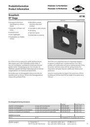
Stellantriebe mit nicht drehender Spindel ....... MMS 19 ... NEU M135Steuerkarten, Universal-Positioniersteuerkarte . PS 30 .............. M143Steuerungen, Positioniersteuerung ................ Ps 10 ....... NEU M139Steuerungen, Universal-Positioniersteuerung . Ps 35 ....... NEU M145Steuerungen, Universal-Positioniersteuerung . PS 90 ............. M149XY <strong>Stages</strong>, precision ..................................... CROSS 152 ...... M103XY <strong>Stages</strong>, precision (compact) .................... PKTM 50 ...........M87XY <strong>Stages</strong>, precision (compact) .................... PKTM 70 ...........M87XY <strong>Stages</strong>, precision (compact) .................... PKTM 100 ......... M91XY <strong>Stages</strong>, precision (compact) .................... PKTM 130 .......... M91Symbolerklärung:Zur Schnellsuche der passenden <strong>Pro</strong>dukte wurden einige Symbolein die <strong>Pro</strong>duktinformationen eingefügt.40 System SYS 40 kompatibelSymbol Legend:In order to rapidly find the corresponding products, some symbolshave been added to the product informations.40 for use with system SYS 4065 System SYS 65 kompatibel65 for use with system SYS 6590 System SYS 90 kompatibelV -6 vakuumpräparierte Versionenunmagnetische Varianten90 for use with system SYS 90V -6 vacuum-prepared versionsnon-magnetic versionsMIIÄnderungen vorbehalten.Subject to change without notice.
Präzision in Perfektion<strong>Precision</strong> in PerfectionTypenbezeichnungenCROSS 50 ........ Kreuztische, Hochpräzisions- (kompakt) .......... M95CROSS 70 ........ Kreuztische, Hochpräzisions- (kompakt) .......... M95CROSS 100 ...... Kreuztische, Hochpräzisions- (kompakt) ..........M99CROSS 130 ...... Kreuztische, Hochpräzisions- (kompakt) ..........M99CROSS 152 ...... Kreuztische, Präzisions- ................................ M103DMT 40 ........... Drehmesstische .............................................M121DMT 65 ........... Drehmesstische ............................................ M123DMT 100 ......... Drehmesstische ............................................ M125DMT 130 ......... Drehmesstische ............................................ M127DMT 200 ......... Drehmesstische ............................................ M129DRTM 40 ......... Drehtische .....................................................M115DRTM 65 ......... Drehtische .....................................................M117HVM 60 .......... Höhenverstelltische ...................................... M105HVM 100 ........ Höhenverstelltische ...................................... M107HVM 200 ........ Höhenverstelltische .......................................M111KTM 40 ........... Kreuztische ....................................................M83KTM 65 ........... Kreuztische .................................................... M85LIMES 60 ......... <strong><strong>Linear</strong>tische</strong>, Hochpräzisions- .......................... M47LIMES 64 ......... <strong><strong>Linear</strong>tische</strong>, Hochpräzisions- .................NEU . M51LIMES 80 ......... <strong><strong>Linear</strong>tische</strong>, Hochpräzisions- .......................... M55LIMES 84 ......... <strong><strong>Linear</strong>tische</strong>, Hochpräzisions- .................NEU . M59LIMES 122 ....... <strong><strong>Linear</strong>tische</strong>, Hochpräzisions- ..........................M63LIMES 124 ....... <strong><strong>Linear</strong>tische</strong>, Hochpräzisions- .................NEU .M67LIMES 150 ....... <strong><strong>Linear</strong>tische</strong>, Hochpräzisions- .......................... M75LIMES 170 ....... <strong><strong>Linear</strong>tische</strong>, Hochpräzisions- .......................... M79LM 45 ............. <strong>Linear</strong>messtische .............................................. M1LTM 60 ............ <strong><strong>Linear</strong>tische</strong>, Präzisions- ................................... M3LTM 60F .......... <strong><strong>Linear</strong>tische</strong>, Präzisions- ................................. M11LTM 60M ........ <strong><strong>Linear</strong>tische</strong>, Präzisions- ........................NEU . M15LTM 60P .......... <strong><strong>Linear</strong>tische</strong>, Präzisions- ................................... M7LTM 80 ............ <strong><strong>Linear</strong>tische</strong>, Präzisions- ................................. M19LTM 80F .......... <strong><strong>Linear</strong>tische</strong>, Präzisions- ................................. M27LTM 80M ........ <strong><strong>Linear</strong>tische</strong>, Präzisions- ........................NEU . M31LTM 80P .......... <strong><strong>Linear</strong>tische</strong>, Präzisions- ................................. M23LTM 120 .......... <strong><strong>Linear</strong>tische</strong>, Präzisions- ................................. M35LTM 120F ........ <strong><strong>Linear</strong>tische</strong>, Präzisions- ................................. M39LTM 120M ....... <strong><strong>Linear</strong>tische</strong>, Präzisions- ........................NEU . M43MMS 19 .......... Stellantriebe mit nicht drehender Spindel NEU M135MOGO 40 ....... Goniometer ...................................................M131MOGO 65S ...... Goniometer .................................................. M133OWISoft .......... Software, Steuerungssoftware ...................... M137PKTM 50 ......... Kreuztische, Präzisions- (kompakt) ..................M87PKTM 70 ......... Kreuztische, Präzisions- (kompakt) ..................M87PKTM 100 ....... Kreuztische, Präzisions- (kompakt) .................. M91Type designationCROSS 50 ........XY <strong>Stages</strong>, high-precision (compact) ............... M95CROSS 70 ........XY <strong>Stages</strong>, high-precision (compact) ............... M95CROSS 100 ......XY <strong>Stages</strong>, high-precision (compact) ...............M99CROSS 130 ......XY <strong>Stages</strong>, high-precision (compact) ...............M99CROSS 152 ......XY <strong>Stages</strong>, precision ..................................... M103DMT 40 ...........Rotary Measuring <strong>Stages</strong> ...............................M121DMT 65 ...........Rotary Measuring <strong>Stages</strong> .............................. M123DMT 100 .........Rotary Measuring <strong>Stages</strong> .............................. M125DMT 130 .........Rotary Measuring <strong>Stages</strong> .............................. M127DMT 200 .........Rotary Measuring <strong>Stages</strong> .............................. M129DRTM 40 .........Rotary <strong>Stages</strong> ................................................M115DRTM 65 .........Rotary <strong>Stages</strong> ................................................M117HVM 60 ..........Elevator <strong>Stages</strong> ............................................. M105HVM 100 ........Elevator <strong>Stages</strong> ............................................. M107HVM 200 ........Elevator <strong>Stages</strong> ..............................................M111KTM 40 ...........XY <strong>Stages</strong> .......................................................M83KTM 65 ...........XY <strong>Stages</strong> ....................................................... M85LIMES 60 .........<strong>Linear</strong> <strong>Stages</strong>, high-precision .......................... M47LIMES 64 .........<strong>Linear</strong> <strong>Stages</strong>, high-precision ..............NEW ... M51LIMES 80 .........<strong>Linear</strong> <strong>Stages</strong>, high-precision .......................... M55LIMES 84 .........<strong>Linear</strong> <strong>Stages</strong>, high-precision ..............NEW ... M59LIMES 122 .......<strong>Linear</strong> <strong>Stages</strong>, high-precision ..........................M63LIMES 124 .......<strong>Linear</strong> <strong>Stages</strong>, high-precision ..............NEW ...M67LIMES 150 .......<strong>Linear</strong> <strong>Stages</strong>, high-precision .......................... M75LIMES 170 .......<strong>Linear</strong> <strong>Stages</strong>, high-precision .......................... M79LM 45 .............<strong>Linear</strong> Measuring <strong>Stages</strong> ................................... M1LTM 60 ............<strong>Linear</strong> <strong>Stages</strong>, precision .................................... M3LTM 60F ..........<strong>Linear</strong> <strong>Stages</strong>, precision .................................. M11LTM 60M ........<strong>Linear</strong> <strong>Stages</strong>, precision ......................NEW ... M15LTM 60P ..........<strong>Linear</strong> <strong>Stages</strong>, precision .................................... M7LTM 80 ............<strong>Linear</strong> <strong>Stages</strong>, precision .................................. M19LTM 80F ..........<strong>Linear</strong> <strong>Stages</strong>, precision .................................. M27LTM 80M ........<strong>Linear</strong> <strong>Stages</strong>, precision ......................NEW ... M31LTM 80P ..........<strong>Linear</strong> <strong>Stages</strong>, precision .................................. M23LTM 120 ..........<strong>Linear</strong> <strong>Stages</strong>, precision .................................. M35LTM 120F ........<strong>Linear</strong> <strong>Stages</strong>, precision .................................. M39LTM 120M .......<strong>Linear</strong> <strong>Stages</strong>, precision ......................NEW ... M43MMS 19 ..........Actuators with non-turning spindle .....NEW . M135MOGO 40 .......Goniometers ..................................................M131MOGO 65S ......Goniometers ................................................. M133OWISoft ..........Software, Control Software ........................... M137PKTM 50 .........XY <strong>Stages</strong>, precision (compact) .......................M87PKTM 70 .........XY <strong>Stages</strong>, precision (compact) .......................M87PKTM 100 .......XY <strong>Stages</strong>, precision (compact) ....................... M91OWIS GmbHIm Gaisgraben 779219 Staufen (Germany)Tel. +49 (0)76 33/95 04-0Fax +49 (0)76 33/95 04-440info@owis.euwww.owis.euMIII
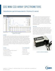
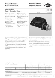
PositionierfehlerGrößte Abweichung der Ist-Positionen von den Sollwerten(Betrachtung des gesamten Positioniersystems mit Führungsungenauigkeiten,Spindelsteigungsfehlern, Lagerspiel und denUnebenheiten der Bauteile). Die Positioniergenauigkeit ist imGegensatz zur Auflösung die tatsächliche erreichte Genauigkeitdes Systems einschließlich Steuerung.Wiederholfehler (Reproduzierbarkeit)Größte Abweichung zweier Ist-Positionen bei beliebigerWiederholung desselben Positioniervorganges. Es wird zwischenunidirektionaler und bidirektionaler Reproduzierbarkeitunterschieden. Bei der unidirektionalen Reproduzierbarkeit wirddieselbe Position immer aus einer Richtung angefahren, beider bidirektionalen Positionierung wird die Position aus beidenRichtungen angefahren.LebensdauerDie Lebensdauer motorisierter Positoniereinheiten ist abhängigvon:Belastungsfallzu tragende Last, Einbaulage, VerfahrgeschwindigkeitBetriebsbedingungenDauerbetrieb, intermittierender Betrieb, UmwelteinflüsseVerwendete Baugruppenverschiedene Spindel- und FührungssystemeDa viele der oben genannten Einflüsse zusammentreffenkönnen, und auch nicht alle Betriebsbedingungen konstantsind, ist es im allgemeinen nicht möglich, Werte für dieLebensdauer anzugeben. Die Lebensdauer bewegt sich imBereich von einigen 100 bis mehreren 1000 Stunden.UmgebungsbedingungenDer Betrieb der Positioniereinheiten sollte bei Raumtemperaturerfolgen. Andere Betriebsbedingungen sind möglich; wendenSie sich hierzu an den technischen Vertrieb.Alle nachfolgenden Meßergebnisse beziehen sich aufRaumtemperatur.Anmerkung zu Positioniereigenschaften bei Belastung:Die gemessenen Werte bezüglich der Positioniereigenschaftengelten für den unbelasteten Fall. Bei hohen Belastungen derPositioniersysteme können diese Angaben nicht gewährleistetwerden. Außerdem hängen die Positioniereigenschaften sehrstark von der Befestigung der Systeme ab.Hochpräzisions-<strong><strong>Linear</strong>tische</strong> LIMES können gegen Aufpreismit einem Messprotokoll mit Angaben über Geradheitsfehler,Gier- und Nickwinkelabweichungen, Positionierfehler sowieUmkehrspiel der Spindel ausgeliefert werden. Die Vermessungerfolgt mit einem Laserinterferometer.Positioning errormaximum deviation of the actual position from the input value.This takes into account the entire positioning system, includingguiding accuracy, spindle pitch errors, bearing backlash, andflatness errors in components. It is the positioning accuracy,not the resolution, that gives the real accuracy of a systemincluding the control system.Repeatabilitythe largest difference between achieved positions, when apositioning operation is repeated any number of times. Adistinction is made between unidirectional and bidirectionalrepeatability. For unidirectional repeatability, a position isalways approached from the same direction; for bidirectionalrepeatability, the position is approached from either direction.Life timeThe life time of motorised positioning units depends on:loadingthe load to be carried, installation position, velocityoperating conditionscontinuous or intermittent duty, environmental influencescomponents employedthe type of spindle and guiding systemBecause many combinations of the above influences arepossible, and often the operating conditions are not constant,it is not possible to give general values for the life time. The lifetime can vary from some hundreds to several thousandsof hours.Environmental conditionsThe positioning units should operate at normal roomtemperature; other conditions are possible, please contact ourtechnical sales staff.All the performance figures quoted here were taken at roomtemperature.Positioning under load:The values for positioning performance were taken on noloadedunits. When the positioning system is loaded heavily,these values cannot be guaranteed. In addition, the positioningproperties depend to a great extent on the mounting of thesystem.High-<strong>Precision</strong> <strong>Linear</strong> <strong>Stages</strong> LIMES can be supplied with acertificate that gives the errors of straightness, yaw and pitchangles, and positioning, also the backlash of the spindle.Measurements are made using a laser interferometer system.MVII
SteuerungstechnikInterfacePC-Steckkarten werden über PCI-Bus verbunden. Steuergerätekönnen über USB oder serielle Schnittstellen (RS 232, RS 485)kommunizieren.Host-RechnerSteuerrechner, der den Betrieb koordiniert. An diesem Rechnerwerden auch die Eingaben (Befehle) für das auszuführende<strong>Pro</strong>gramm editiert.(Daten-) BUSmehrere Datenleitungen für die Informations- bzw.SignalverarbeitungVorranglogikHardwaremäßig verschaltete Logik, die den Endschaltern amPositioniertisch den Vorrang vor den Handtasten der Steuerunggibt (Schrittmotorsteuerung).PWM (Puls-Weiten-Modulation)Zur Ansteuerung überwiegend induktiver Lasten (wie z. B.Motorwicklungen) wird die Motorspannung oder derMotorstrom mit hoher Frequenz getaktet. Die effektiveBetriebsspannung bzw. der effektive Betriebsstrom an denMotorwicklungen entspricht dem zeitlichen Mittelwert desPWM-Signals. Ziel: Verringerung der Verlustleistung in denMotorendstufen.Low-Active-Funktion (der Endschalter)Wird die Verbindung zum Endschalter unterbrochen durchKabelbruch, loser Stecker o.ä., stoppt der Motor.Positionieren mit Gleichstrommotoren (DC-Servo)Durch die Schrittmotorsteuerung wird ein umlaufendesDrehfeld im Schrittmotor generiert, dem der Rotor desSchrittmotors folgt. Ein bürstenkommutierter Gleichstrommotorist nur in der Lage, eine Rotation bzw. ein Drehmoment zuerzeugen und benötigt daher eine Lageerfassung, sowie einegeeignete Regelelektronik. Benutzt eine Positioniereinheiteinen Antrieb mit einem Gleichstrommotor, so muss eineLageregelung über einen geschlossenen Regelkreis („closedloop“) durchgeführt werden. Ein Lagemessglied ist jedochhier unerlässlich, es teilt dem Lageregler die aktuelle Position(Ist-Position) der Antriebseinheit mit. Dies erfolgt rotatorischdurch Erfassen des Rotationswinkels am Motor oder linearmittels Längenmesssystem direkt an der Positioniereinheit. Alsrotierende Lagemessglieder werden meistens InkrementaleDrehgeber eingesetzt.Permanentmagneterregte Gleichstrommotoren mitBürstenkommutierungAnlegen einer Spannung an die sog.„Bürsten“ einesGleichstrommotors bewirkt Entstehung eines Drehmomentsbzw. eine kontinuierliche Drehung an der Motorwelle.Eigenresonanzen treten hierbei – systembedingt – kaum auf.Für manche Applikationen ist der ruhige Motorlauf einesbürstenkommutierten Gleichstrommotors, insbesondere immittleren Drehzahlbereich, sehr vorteilhaft. Ein prinzipbedingterNachteil eines derartigen Systems ist die u.U. etwas längereEinschwingzeit bis zum Erreichen der Zielposition (typ. ca. 50– 500 ms).Unsere DC-Servomotoren sind permanentmagneterregteMotoren. Diese Motoren zeichnen sich dadurch aus, dass derStrom linear mit dem Belastungsdrehmoment ansteigt.Änderungen vorbehalten.MVIIIControl techniqueHardware interfacePC plug in cards are connected via PCI bus. Control unitscommunicate via USB or serial interfaces (RS 232, RS 485).Host computercontrol computer that coordinates operation. The commands forthe program that is to be executed are edited on this computer.(Data) BUSa number of conductors for information and signal processingPriority logichardwired logic that gives the limit switches on a positioningstage priority over manual controls (Step Motor Controller SMS)PWM (Pulse width modulation)In order to control mainly inductive loads (such as motorwindings), the motor voltage or current is switched at highfrequency. The effective voltage (or current) at the motorwinding is then the average over time of the PWM signal.Objective: reduction of losses in the motor amplifier.Low-active function (of the limit switch)If the connection to the limit switch is interrupted e. g. by cablebreakage, loose connection etc., the motor stops. (Safety function)Positioning with DC brush-type motors (DC servo)A step motor controller generates a rotating field. The rotor ofa step motor simply follows that field. A brush-commutatedDC servo can generate an undefined rotation (or a torque,respectively) only, and hence requires the use of a positionfeedback system, containing a suitable electronic device forclosed-loop control. A positioning stage driven by a DC servohas to be equipped with a measuring system (encoder or linearmeasuring system) for capture of its actual position.Permanent-magnet excited DC motors with brushcommutationA voltage applied to the so-called „brushes“ of a DC motorcauses generation of a rotation or a certain torque at themotor shaft. Characteristic resonance phenomena do not haveto be expected, contrary to the behaviour of a step motor. Forsome applications, the quiet and soft motor run of a DC servo,particulary when using a medium speed range, is favourable.A system-dependent disadvantage of a servo system might bea certain settling time for reaching the target position (approx.50…500 ms, typically).Our DC servo motors of the DS series are permanent-magnetexcited motors. They are characterized by the fact that thesupply current increases nearly linear with the output torque.Subject to change without notice.
Dadurch ist ein hoher Wirkungsgrad über den gesamtenBetriebsbereich möglich. Weitere Vorteile sind das hoheAnzugsmoment und die einfache Änderung der Drehzahldurch Erhöhen oder Herabsetzen der Speisespannung. DieDrehrichtung des Motors ist definiert über die Polarität derangelegten Spannung.WegmessungEin DC-Motor kann „nur“ eine Drehung erzeugen. ZurErfassung des zurückgelegten Weges setzt man üblicherweiseinkrementale Wegsensoren, wie z. B. Drehgeber oder<strong>Linear</strong>messsysteme, ein.Drehgeber (Encoder)Der Drehgeber wird am zweiten Wellenende des DC-Motorsangeflanscht. Ein inkrementaler Drehgeber besitzt üblicherweiseeine Scheibe, die in bestimmten Abständen Schlitze hat. Dasdurch die Drehung der Scheibe entstehende Hell-Dunkel-Musterwird mit Hilfe von LEDs und Photodioden bzw. Phototransistorenabgetastet. Aus den daraus gewonnenen Signalen lassen sichDrehrichtung und Wegstrecke ableiten.Index (Nullspur)Referenzmarke eines inkrementalen Wegmesssystems;ermöglicht Referenzfahrt der Positioniereinheit auf± 1 Inkrement. Beim Drehgeber (Encoder) ist eine Markierungpro Motorumdrehung üblich. Längenmesssysteme könnenmehrere Referenzmarken besitzen.Leitungstreiber/Leitungsempfänger:Spezielle Technik zur Übertragung von Digital- oder Analogsignalenmit erhöhter Störsicherheit bei größeren Leitungslängenüber leistungsstarke Differenzialtreiber und -empfänger.Dabei wird ein Treiber mit dem korrespondierenden Empfängerüber ein verdrilltes Aderpaar verbunden. Anwendung speziellbei Drehgebern oder <strong>Linear</strong>messsystemen.<strong>Linear</strong>messsystemInkrementale Längenmesssysteme funktionieren ähnlich wiedie inkrementalen Drehgeber. Die Signale entstehen durch einbestimmtes Hell-Dunkel-Muster, welches linear angeordnetist (auf Metallstreifen oder Glasstäben). Bei OWIS werdenGlasmaßstäbe verwendet, auf denen der inkrementale Codeaufgebracht ist. Der Einsatz von <strong>Linear</strong>messsystemen anstellevon Drehgebern ist dort notwendig, wo eine besonders hoheReproduzierbarkeit der Position gefordert wird, oder wo ein<strong>Linear</strong>antrieb anstelle eines Spindelantriebs eingesetzt wird. Eslassen sich damit die tatsächlich gefahrenen Wegstrecken direktam System (Schlitten) messen.Positionieren mit SchrittmotorenSchrittmotoren setzen unmittelbar elektrische Impulse ineinen entsprechenden analogen Winkel oder Weg, bzw.eine Impulsfrequenz in eine Dreh- oder Vorschubbewegungum. Der Verstellwinkel des Rotors entspricht somitden von der Ansteuerung gelieferten Impulsen und dieVerstellgeschwindigkeit entspricht der Impulsfrequenz.Konstruktionsbedingt ist der Schrittmotor der ideale Antrieb fürdie meisten Positionieraufgaben. Der lineare Zusammenhangzwischen Impulszahl der Ansteuerung und Drehwinkel desRotors bzw. Hub bei <strong>Linear</strong>antrieben erübrigt den aufwendigenEinsatz von Lagesensoren. Im Stillstand wird der Rotor inseiner momentanen Lage mit dem maximalen Drehmoment(Haltemoment) fixiert. Um die Verluste durch Abwärme imStillstand zu reduzieren, kann der Haltestrom reduziert werdenThereby it is possible to obtain a high efficiency over the wholeoperation range. Further advantages are the high startingtorque and the simple velocity variation by increasing orreducing the supply voltage when driving a constant torque.The rotation direction of the motor is defined by the polarity ofthe applied voltage.Displacement measurementA DC servo motor can only generate a rotation. For gatheringof the actual position, one can use incremental optical sensors,e. g. rotary impulse generators or linear measuring systems.Rotary pulse generator (optical encoder):IndexThe rotary pulse generator is fitted usually to the second shaftof the motor. The main component of an incremental encoderis a disk having slots in a certain distance. Turning of the diskgenerates light-dark samples scanned by LEDs and photodiodesor phototransistors. Out of the taken signals direction ofrotation and the covered distance can be derived.the reference mark of an incremental travel measuring systemIt allows a reference motion of the positioning unit up to±1 increment. For rotary impulse generators, one mark permotor revolution is normal. <strong>Linear</strong> measuring systems can haveseveral reference marks.Line amplifier/line receiverspecial technology for transferring digital or analogue signalsthrough long leads, providing high resistance to interference.A high-performance differential amplifier is connected to itsreceiver by a twisted-pair cable. This technology is appliedalmost exclusively to angular and linear measuring systems.<strong>Linear</strong> measuring systemIncremental linear measuring systems work in a similar wayto rotary encoders. The signal is created by a certain light/darkpattern, in this case arranged in a linear manner on metalstrips, or glass scales (as used by OWIS). <strong>Linear</strong> measuringsystems (LMS) are used instead of rotary encoders whenvery high repeatability of position is demanded, or where alinear drive is employed instead of a spindle drive. With sucha system, the actual path travelled is measured directly at thecarriage.Positioning with step motorsStep motors convert electrical pulses directly into theappropriate angle or travel distance, or a pulse sequence into afeed motion. Thus, the rotation angle of the rotor correspondsto the pulse number supplied by the control unit, and thefeed rate corresponds to the pulse frequency. For reasons ofdesign, the step motor is the ideal driver for most positioningtasks. The linear connection between pulse number and rotorrotation angle, respectively the travel distance of a linear stage,avoids a possibly complex use of position sensors. At standstill,the rotor is fixed in its position at maximum torque (the socalled „holding torque“). To reduce the heat dissipation of themotor at standstill, the holding current can be reduced (phasecurrent reduction at standstill). The so-called „hybrid-type“step motor is the most popular step motor design because ofMIX
(Phasenstromreduktion im Stillstand). Die weiteste Verbreitungunter den Schrittmotoren hat heute wegen seiner gutenLaufeigenschaften der Hybridschrittmotor gefunden. Dieservereinigt die Vorteile eines Permanentmagnetschrittmotors,wie z.B. hohes Drehmoment, mit denen eines Schrittmotorsmit variabler Reluktanz, wie kleine Schrittweite und weicherAnlauf. Unsere Schrittmotoren der Serie SM sind 2-Phasen-Hybridschrittmotoren für unipolare oder bipolare Betriebsart.Die beiden Phasenwicklungen werden üblicherweise mit A undB bezeichnet.Bipolar-BetriebDie Polarität der angelegten Spannung wird umgedreht, sodassdie Stromflussrichtung je einer Wicklung von Vollschritt zuVollschritt umgepolt wird. Je zwei Wicklungen (8-Leiter- Motor)werden in dieser Betriebsart durch Parallelschaltung oderSerienschaltung zu einer Motor-Phase zusammengefasst.Unipolar-BetriebDie angelegte Spannung hat immer gleiche Polarität, d.h., derStrom fließt in jeder Halbwicklung (A, A _ bzw. B, B _ ) immer indie gleiche Richtung. Die erforderliche Flussrichtungsumkehrwird durch wahlweise Bestromung der einen oder anderenHalbwicklung realisiert.Mikroschritt-BetriebSchaltet man die Ströme in den Strängen nicht abruptaus oder um, sondern verändert man die Phasenströme inkleinen Schritten nahezu kontinuierlich, ergibt sich der sog.Mikroschrittbetrieb. Die Stromverläufe im Mikroschrittbetriebsind sinus-/cosinusförmig, wobei die glatten Kurven in derPraxis durch Treppenkurven approximiert werden.Start-Stop-BetriebFür einfache Positioniervorgänge ohne besondere Geschwindigkeitsanforderungkann der Schrittmotor im Start-Stopp-Betriebangesteuert werden. Ist es erforderlich, einen Motor oberhalbder Start-Stopp-Frequenz zu betreiben, so muss er unterhalbder für das System gültigen Start-Stopp-Frequenz gestartet unddann bis zur gewünschten Endfrequenz beschleunigt werden.Soll der Motor jedoch angehalten werden, muss er unter dieStart-Stopp-Frequenz abgebremst und dann gestoppt werden.Diese Charakteristik ist sowohl für unipolare als auch fürbipolare Schrittmotoren gültig.its superior running characteristics. It combines the advantagesof a permanent-magnet step motor, such as high torque, withthose of a step motor with variable reluctance, such as smallstep angle and a soft start. Our step motors of the SM seriesare 2-phase hybrid-type step motors for unipolar and bipolaroperation modes. Both phase coils are designated usually with„A“ and „B“.Bipolar mode operationThe polarity of the applied voltage is being reversed, so thatthe current flow direction in one coil is reversed from each fullstep to the next full step. When using 8-lead wire motor typeswith 4 coils, two coils each have to be interconnected into onemotor phase by an appropriate parallel or serial wiring in thisoperation mode.Unipolar mode operationThe polarity of the applied voltage is always the same, i.e.,the current flow in each half coil (A, A _ , respectively B, B _ ) isalways into the same direction. The necessary reversal of thecurrent flow direction from one full step to the next is realizedby switching the supply voltage from the first half coil to thesecond half coil.Micro step operationInstead of an abrupt change of the motor coil currents onecan change them nearly continuously in very small steps. Thisoperation mode is called „micro step mode“. Theoretically,in ideal micro step operation the resulting current curves aresinusoidal. The ideal sinusoidal curves are approximated bysmall steps in practice.Start-stop mode operationFor simple positioning processes without especially high feedrate request, the step motor can be driven in start-stop modeoperation. If it should be necessary to use a step motor abovethe start-stop frequency, it has to be started below the system‘svalid start-stop frequency and accelerated up to the desiredfinal frequency, using an appropriate acceleration ramp. If thestep motor is to be stopped, however, it must be deceleratedbelow the start-stop frequency and stopped then. Thischaracteristic is valid for both, unipolar and bipolar step motors.MXÄnderungen vorbehalten.Subject to change without notice.
<strong>Pro</strong>duktinformation<strong>Pro</strong>duct InformationPräzision in Perfektion<strong>Precision</strong> in Perfection<strong>Linear</strong>messtische<strong>Linear</strong> Measuring <strong>Stages</strong>• Stellweg 12 mm• verzugsarmes Aluminium,schwarz eloxiert• geschliffeneFeingewindespindel• Schlitten mit Kreuzrollenführungen• mechanische Endschalter• 2-Phasen-Getriebeschrittmotoroder DC-Getriebemotormit Encoder• travel 12 mm• deformation-resistantaluminium, black anodized• ground fine-thread spindle• carriage with crossed rollerbearing guides• mechanical limit switches• 2-phase geared step motoror geared DC motor withencoder40 65 90 V -6 V -6LM 459012. 0057 Ausgabe 05.05.2009Durch seine kompakte und flache Bauweise ist der <strong>Linear</strong>tischLM 45 für Anwendungen mit eingeengten Platzverhältnissengeeignet.Die speziellen Führungen sorgen für praktisch spielfreien Laufsowie für hohe Belastbarkeit. Die Werkstoffkombination vonGewindespindel und Mutter gewährleistet geringen Verschleiß undhohe Lebensdauer.Alle Aluminiumteile haben eine hochwertige schwarze Eloxal-Schutzschicht.Compact and flat form design makes LM 45 suitable for use indemanding limited space applications.The special guidance provides a practically backlash-free movementas well as high load capacity. The material combination of spindleand nut ensures low abrasion and long life time.All aluminium parts have a top quality black anodized protectivecoating.Bestellangaben/Ordering Information<strong>Linear</strong>messtische/linear measuring stagesmit 2-Phasen-Getriebeschrittmotorwith 2-phase geared step motormit DC-Getriebemotor mit Encoderwith geared DC servo motor with encoderTyp/type Bestell-Nr./part no. Typ/type Bestell-Nr./part no.12 mm Stellweg/travel LM 45-13-MSM 41.040.016B LM 45-13-MDS 41.040.011BZubehör/AccessoriesMontageplatte mounting plate MP 45 31.999.0045Sonderfett für Spindel, 5 ml im Applikator special grease for spindle, 5 ml within applicator SST.F11 90.999.0011Sonderfett für Kreuzrollenführungen,5 ml im Applikatorspecial grease for crossed roller bearing guides,5 ml within applicatorSST.F1 90.999.0001OWIS GmbHIm Gaisgraben 779219 Staufen (Germany)Tel. +49 (0)76 33/95 04-0Fax +49 (0)76 33/95 04-440info@owis.euwww.owis.euM1
Ø 3 311834 M4 430 Ø3 320 M3 4Ø 3 3Snkg. f. M4cntrb. f. M420 M3 4Snkg. f. M4 von untencntrb. f. M4 from the bottom259M4 4Ø3 330162048451525253015255511813861621101 2BMB'A'AB 1B2A4A 3GND8MINSTOP9MAXSTOP10F 250 mAF 250 mAMotorleitungen absichern!To be fused!Im Stecker des OWIS-Anschlusskabels53.16.S300 sind diese Sicherungen eingebaut.The fuses are integrated in the connector ofthe OWIS connecting cable 53.16.S300.Öffner/normally closedSchaltvermögen/switching abilitymax. 30 V, max. 0,1 AM10kEncoderMotor +6VCC2 + 5 VDCCHA 4CHB 3GND 5Motor –1nc 7GND 8MINSTOP 9MAXSTOP 10Öffner/normally closedSchaltvermögen/switching abilitymax. 30 V, max. 0,1 AInduktive Lasten müssen mit einer geeigneten Funkenlöschung versehen sein.Inductances must have a suitable spark supression.Steckerbelegung/pin configuration LM 45-XXX-MSMInduktive Lasten müssen mit einer geeigneten Funkenlöschung versehen sein.Inductances must have a suitable spark supression.Steckerbelegung/pin configuration LM 45-XXX-MDSTechnische Daten/Technical Data LM 45 (bei 20 °C/@20 °C, ohne Last/no load)SchrittmotorStep motorDC-ServomotorDC servo motorStellweg travel 12 mmGeschwindigkeit velocity max. 0,1 max. 0,2 mm/sTragkraft load capacity max. 20 NStellkraft actuating force max. 10 NKippmoment (Mx, My, Mz) moment of tilt (Mx, My, Mz) max. 2,0 NmSpindelsteigung spindle pitch 0,4 mmGetriebeuntersetzung gear reduction 7817:103Wiederholfehler (bidirektional) repeatability (bidirectional)
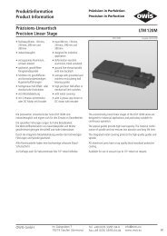
<strong>Pro</strong>duktinformation<strong>Pro</strong>duct InformationPräzision in Perfektion<strong>Precision</strong> in PerfectionPräzisions-<strong><strong>Linear</strong>tische</strong><strong>Precision</strong> <strong>Linear</strong> <strong>Stages</strong>• Stellweg 25 mm, 50 mm,70 mm, 95 mm und 145 mm• industrietauglich• verzugsarmes Aluminium,schwarz eloxiert• geschliffeneFeingewindespindel mitspielfreier Axiallagerung• Schlitten mit Kugelumlaufführungen• rostbeständige, geschliffeneStahl-Führungsschienen• hochgenaue Hall-Effekt odermechanische Endschalter• mit 2-Phasen-Schrittmotoroder DC-Motor mit Encoder• travel 25 mm, 50 mm, 70 mm,95 mm and 145 mm• designed for industrialapplication• deformation-resistantaluminium, black anodized• ground fine thread spindlewith backlash-free axialbearings• carriage with recirculatingball bearings• stainless, ground steel guides• high-precision Hall-effect ormechanical limit switches• with 2-phase step motoror DC motor with encoder40 65 90 V -6 V -6LTM 609012. 0052 Ausgabe 05.05.2009Die preiswerten <strong><strong>Linear</strong>tische</strong> der Serie LTM 60 eignen sich für denEinsatz im Dauerbetrieb und den Einbau in Maschinen.Die speziellen Führungen sorgen für praktisch slip-stick-freienLauf sowie für hohe Belastbarkeit. Die Werkstoffkombination vonGewindespindel und Mutter gewährleistet geringen Verschleiß undhohe Lebensdauer.Alle Aluminiumteile haben eine hochwertige schwarze Eloxal-Schutzschicht.The economically priced linear stages of the series LTM 60 seriesare particulary suitable for continuous operation and installation inmachines.The special guides provide practically slip-stick free movement aswell as high load capacity. The material combination of spindle andnut ensures low abrasion and long life time.All aluminium parts have a top quality black anodized protectivecoating.Technische Daten/Technical Data (bei 20 °C/@20 °C, ohne Last/no load)Schrittmotorstep motorDC-ServomotorDC servo motorGeschwindigkeit velocity max. 10 mm/sTragkraft load capacity max. 100 NStellkraft actuating force max. 50 max. 30 NKippmoment (Mx, My, Mz) moment of tilt (Mx, My, Mz) max.7,5 NmSpindelsteigung spindle pitch 1 mmWiederholfehler (bidirektional) repeatability (bidirectional)
max.Tragkraft/load capacityStellkraft/pushing force min.32,5Ø8442,5Ø4,5123mit DC-Servomotorwith DC servo motor305022087LTM 60-150mit Schrittmotorwith step motor71503025170LTM 60-10017,52514550LTM 60-75M6x530 ø3 x 634 M4 x 840 M4 x 850 M4 x 860LTM 60-5032,51255030 ø3 x 660LTM 60-252010050M4Änderungen vorbehaltenSubject to change without notice
AMA'BB'Hallsensoren/hall sensorsAA'BB'V CCMINSTOPMINDECMAXDECMAXSTOPGND123481112141513DSub-HD-15 male1 56 1011 155, 6, 7, 9, 10 n.c.+4 bis/up to +24 VDCSchaltvermögen/switching abilitymax. 24 VDC, max. 20 mAInduktive Lasten müssen mit einergeeigneten Funkenlöschung versehen sein.Inductances must have a suitablespark supressionAMA'BB'Endschalter/limit switch min.11Endschalter/limit switch GND 13Endschalter/limit switch max.15AA'BB'1234DSub-HD-15 male1 56 1011 155, 6, 7, 8, 9, 10, 12, 14 n.c.Schaltvermögen/switching abilitymax. 30 VDC, max. 1 AInduktive Lasten müssen mit einergeeigneten Funkenlöschung versehen sein.Inductances must have a suitablespark supressionSteckerbelegung/pin configuration LTM 60-XXX-HSMSteckerbelegung/pin configuration LTM 60-XXX-MSMMEncoderHallsensoren/hall sensorsMotor +V CCCHACHACHBCHBINDEXMotor –MINSTOPMINDECMAXDECMAXSTOPGND7159 + 5 VDC31112486141025131DSub-15 male1 89 15TTL, max. 20 mA,nicht kurzschlussfest/not short-circuit proofInduktive Lasten müssen mit einer geeignetenFunkenlöschung versehen seinInductances must have a suitablespark supressionÖffner/normally closedSchaltvermögen/switching abilitymax. 24 VDC, max. 20 mAMEncoderMotor +V CCCHACHACHBCHBINDEXMotor –MINSTOPMINDECMAXDECMAXSTOPGND7159 + 5 VDC31112486141025131DSub-15 male1 89 15TTL, max. 20 mA,nicht kurzschlussfest/not short-circuit proofInduktive Lasten müssen mit einer geeignetenFunkenlöschung versehen seinInductances must have a suitablespark supressionÖffner/normally closedSchaltvermögen/switching abilitymax. 30 VDC, max. 1 ASteckerbelegung/pin configuration LTM 60-XXX-HDSSteckerbelegung/pin configuration LTM 60-XXX-MDSM5
Bestellangaben/Ordering InformationPräzisions-<strong><strong>Linear</strong>tische</strong>/precision linear stagesmit Hall-Effekt-Endschalternwith Hall-effect limit switchesmit mechanischen Endschalternwith mechanical limit switchesmit Schrittmotor/with step motor Typ/type Bestell-Nr./part no. Typ/type Bestell-Nr./part no.25 mm Stellweg/travel LTM 60-25-HSM 41.063.25AC LTM 60-25-MSM 41.063.25BC50 mm Stellweg/travel LTM 60-50-HSM 41.063.50AC LTM 60-50-MSM 41.063.50BC70 mm Stellweg/travel LTM 60-75-HSM 41.063.75AC LTM 60-75-MSM 41.063.75BC95 mm Stellweg/travel LTM 60-100-HSM 41.063.10AC LTM 60-100-MSM 41.063.10BC145 mm Stellweg/travel LTM 60-150-HSM 41.063.15AC LTM 60-150-MSM 41.063.15BCmit Hall-Effekt-Endschalternwith Hall-effect limit switchesmit mechanischen Endschalternwith mechanical limit switchesmit DC-Servomotor/with DC servo mot Typ/type Bestell-Nr./part no. Typ/type Bestell-Nr./part no.25 mm Stellweg/travel LTM 60-25-HDS 41.063.25LE LTM 60-25-MDS 41.063.25PE50 mm Stellweg/travel LTM 60-50-HDS 41.063.50LE LTM 60-50-MDS 41.063.50PE70 mm Stellweg/travel LTM 60-75-HDS 41.063.75LE LTM 60-75-MDS 41.063.75PE95 mm Stellweg/travel LTM 60-100-HDS 41.063.10LE LTM 60-100-MDS 41.063.10PE145 mm Stellweg/travel LTM 60-150-HDS 41.063.15LE LTM 60-150-MDS 41.063.15PEZubehör/AccessoriesZ-Montagesatz für LT 60, LTM 60, LTM 60P, F und M, Z assembly kit, for LT 60, LTM 60, LTM 60P, F and M, MONT-LT(M) 60-Z 41.063.0001LIMES 60 und LIMES 64LIMES 60 and LIMES 64Z-Montagesatz kurz, für LT 60, LTM 60, LTM 60P, F und M, Z assembly kit short, for LT 60, LTM 60 and LTM 60P, MONT-LT(M) 60-Z-K 41.063.0005LIMES 60 und LIMES 64 bis 70 mm Stellweg F and M, LIMES 60 und LIMES 64 up to 70 mm travelXY-Montagesatz für LT , LTM und LIMES, inkl. Montage XY assembly kit for LT, LTM , LIMES, incl. assembly MONT-LT(M)-XY 41.083.0004Fett für Spindel, 5 ml im Applikator grease for spindle, 5 ml in applicator SST.F11 90.999.0011Fett für Führungen, 5 ml im Applikator grease for guides, 5 ml in applicator SST.F2 90.999.0002M6Änderungen vorbehaltenSubject to change without notice
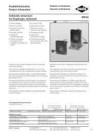
<strong>Pro</strong>duktinformation<strong>Pro</strong>duct InformationPräzision in Perfektion<strong>Precision</strong> in PerfectionPräzisions-<strong><strong>Linear</strong>tische</strong><strong>Precision</strong> <strong>Linear</strong> <strong>Stages</strong>• Stellweg 25 mm, 50 mm,70 mm, 95 mm und 145 mm• industrietauglich• verzugsarmes Aluminium,schwarz eloxiert• geschliffeneFeingewindespindel mitspielfreier Axiallagerung• Schlitten mit Kugelumlaufführungen• rostbeständige, geschliffeneStahl-Führungsschienen• hochgenaue Hall-Effekt odermechanische Endschalter• parallel montierter2-Phasen-Schrittmotoroder DC-Motor mit Encoder• travel 25 mm, 50 mm, 70 mm,95 mm and 145 mm• designed for industrialapplication• deformation-resistantaluminium, black anodized• ground fine thread spindlewith backlash-free axialbearings• carriage with recirculatingball bearings• stainless, ground steel guides• high-precision Hall-effect ormechanical limit switches• with parallel mounted2-phase step motoror DC motor with encoder40 65 90 V -6 V -6LTM 60P9012. 0054 Ausgabe 05.05.2009Die preiswerten <strong><strong>Linear</strong>tische</strong> der Serie LTM 60P eignen sich für denEinsatz im Dauerbetrieb und den Einbau in Maschinen. Durch diespezielle Anordnung des Antriebs ist ein großer Stellweg untergeringem Platzbedarf möglich.Die speziellen Führungen sorgen für praktisch slip-stick-freienLauf sowie für hohe Belastbarkeit. Die Werkstoffkombination vonGewindespindel und Mutter gewährleistet geringen Verschleiß undhohe Lebensdauer.Alle Aluminiumteile haben eine hochwertige schwarze Eloxal-Schutzschicht.Technische Daten/Technical Data (bei 20 °C/@20 °C, ohne Last/no load)The economically priced linear stages of the series LTM 60P seriesare particulary suitable for continuous operation and installationin machines. A long travel due to the drive is achieveable by smallrequierd space.The special guides provide practically slip-stick free movement aswell as high load capacity. The material combination of spindle andnut ensures low abrasion and long life time.All aluminium parts have a top quality black anodized protectivecoating.Schrittmotorstep motorDC-ServomotorDC servo motorGeschwindigkeit velocity max. 10 mm/sTragkraft load capacity max. 100 NStellkraft actuating force max. 40 max. 25 NKippmoment (Mx, My, Mz) moment of tilt (Mx, My, Mz) max.7,5 NmSpindelsteigung spindle pitch 1 mmWiederholfehler (bidirektional) repeatability (bidirectional)
max.Tragkraftload capacityStellkraftpushing forcemin.32,5Ø8442,5Ø4,5mit DC-Servomotorwith DC servo motor13513024030 5030LTM 60 P-1507150135mit Schrittmotorwith step motor733025190LTM 60 P-10017,52516550LTM 60 P-75M6x530 ø3 x 634 M4 x 740 M4 x 750 M4 x 760LTM 60 P-5032,514550201205030 ø3 x 660LTM 60 P-25M8Änderungen vorbehaltenSubject to change without notice
AMA'BB'Hallsensoren/hall sensorsAA'BB'V CCMINSTOPMINDECMAXDECMAXSTOPGND432181112141513DSub-HD-15 male1 56 1011 155, 6, 7, 9, 10 n.c.+4 bis/up to +24 VDCSchaltvermögen/switching abilitymax. 24 VDC, max. 20 mAInduktive Lasten müssen mit einergeeigneten Funkenlöschung versehen sein.Inductances must have a suitablespark supressionAMA'BB'Endschalter/limit switch min.11Endschalter/limit switch GND 13Endschalter/limit switch max.15AA'BB'4321DSub-HD-15 male1 56 1011 155, 6, 7, 8, 9, 10, 12, 14 n.c.Schaltvermögen/switching abilitymax. 30 VDC, max. 1 AInduktive Lasten müssen mit einergeeigneten Funkenlöschung versehen sein.Inductances must have a suitablespark supressionSteckerbelegung/pin configuration LTM 60P-XXX-HSMSteckerbelegung/pin configuration LTM 60P-XXX-MSMMEncoderMotor +V CCCHACHACHBCHBINDEX6149 + 5 VDC1243118DSub-15 male1 89 15TTL, max. 20 mA,nicht kurzschlussfest/not short-circuit proofMEncoderMotor +V CCCHACHACHBCHBINDEX6149 + 5 VDC1243118DSub-15 male1 89 15TTL, max. 20 mA,nicht kurzschlussfest/not short-circuit proofHallsensoren/hall sensorsMotor –MINSTOPMINDECMAXDECMAXSTOPGND7151025131Induktive Lasten müssen mit einer geeignetenFunkenlöschung versehen seinInductances must have a suitablespark supressionÖffner/normally closedSchaltvermögen/switching abilitymax. 24 VDC, max. 20 mAMotor –MINSTOPMINDECMAXDECMAXSTOPGND7151025131Induktive Lasten müssen mit einer geeignetenFunkenlöschung versehen seinInductances must have a suitablespark supressionÖffner/normally closedSchaltvermögen/switching abilitymax. 30 VDC, max. 1 ASteckerbelegung/pin configuration LTM 60P-XXX-HDSSteckerbelegung/pin configuration LTM 60P-XXX-MDSM9
Bestellangaben/Ordering InformationPräzisions-<strong>Linear</strong>tisch/precision linear stagemit Hall-Effekt-Endschalternwith Hall-effect limit switchesmit mechanischen Endschalternwith mechanical limit switchesSmit Schrittmotor/with step motor Typ/type Bestell-Nr./part no. Typ/type Bestell-Nr./part no.25 mm Stellweg/travel LTM 60P-25-HSM 41.065.25AC LTM 60P-25-MSM 41.065.25BC50 mm Stellweg/travel LTM 60P-50-HSM 41.065.50AC LTM 60P-50-MSM 41.065.50BC70 mm Stellweg/travel LTM 60P-75-HSM 41.065.75AC LTM 60P-75-MSM 41.065.75BC95 mm Stellweg/travel LTM 60P-100-HSM 41.065.10AC LTM 60P-100-MSM 41.065.10BC145 mm Stellweg/travel LTM 60P-150-HSM 41.065.15AC LTM 60P-150-MSM 41.065.15BCmit Hall-Effekt-Endschalternwith Hall-effect limit switchesmit mechanischen Endschalternwith mechanical limit switchesmit DC-Servomotor/with DC servo mot Typ/type Bestell-Nr./part no. Typ/type Bestell-Nr./part no.25 mm Stellweg/travel LTM 60P-25-HDS 41.065.25LE LTM 60P-25-MDS 41.065.25PE50 mm Stellweg/travel LTM 60P-50-HDS 41.065.50LE LTM 60P-50-MDS 41.065.50PE70 mm Stellweg/travel LTM 60P-75-HDS 41.065.75LE LTM 60P-75-MDS 41.065.75PE95 mm Stellweg/travel LTM 60P-100-HDS 41.065.10LE LTM 60P-100-MDS 41.065.10PE145 mm Stellweg/travel LTM 60P-150-HDS 41.065.15LE LTM 60P-150-MDS 41.065.15PEZubehör/AccessoriesZ-Montagesatz für LT 60, LTM 60, LTM 60P, F und M, Z assembly kit, for LT 60, LTM 60, LTM 60P, F and M, MONT-LT(M) 60-Z 41.063.0001LIMES 60 und LIMES 64LIMES 60 and LIMES 64XY-Montagesatz für <strong><strong>Linear</strong>tische</strong> LTM 60P XY assembly kit for series LTM 60P linear stages MONT-LTM 60P-XY 41.065.0004Fett für Spindel, 5 ml im Applikator grease for spindle, 5 ml in applicator SST.F11 90.999.0011Fett für Führungen, 5 ml im Applikator grease for guides, 5 ml in applicator SST.F2 90.999.0002Änderungen vorbehaltenM10Subject to change without notice
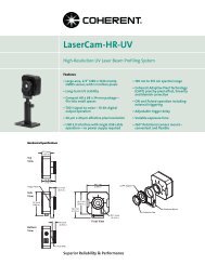
<strong>Pro</strong>duktinformation<strong>Pro</strong>duct InformationPräzision in Perfektion<strong>Precision</strong> in PerfectionPräzisions-<strong><strong>Linear</strong>tische</strong><strong>Precision</strong> <strong>Linear</strong> <strong>Stages</strong>• Stellweg 20 mm, 40 mm,50 mm, 70 mm und 105 mm• industrietauglich• verzugsarmes Aluminium,schwarz eloxiert• geschliffeneFeingewindespindel mitspielfreier Axiallagerung• Schlitten mit Kugelumlaufführungen• rostbeständige, geschliffeneStahl-Führungsschienen• hochgenaue Hall-Effekt odermechanische Endschalter• mit Faltenbalg• mit 2-Phasen-Schrittmotoroder DC-Motor mit Encoder• travel 20 mm, 40 mm, 50 mm,70 mm und 105 mm• designed for industrialapplication• deformation-resistantaluminium, black anodized• ground fine thread spindlewith backlash-free axialbearings• carriage with recirculatingball bearings• stainless, ground steel guides• high-precision Hall-effect ormechanical limit switches• with bellows• with 2-phase step motoror DC motor with encoder40 65 90 V -6 V -6LTM 60F9012. 0053 Ausgabe 06.05.2009Die preiswerten <strong><strong>Linear</strong>tische</strong> der Serie LTM 60F eignen sich für denEinsatz im Dauerbetrieb und den Einbau in Maschinen. Durch denintegrierten Faltenbalg werden die hochwertigen Führungen undSpindel geschützt.Die speziellen Führungen sorgen für praktisch slip-stick-freienLauf sowie für hohe Belastbarkeit. Die Werkstoffkombination vonGewindespindel und Mutter gewährleistet geringen Verschleiß undhohe Lebensdauer. Alle Aluminiumteile haben eine hochwertigeschwarze Eloxal-Schutzschicht.The economically priced linear stages of the LTM 60F series areparticulary suitable for continuous operation and installation inmachines. The integreated bellow protects the high quality guidesand spindle.The special guides provide practically slip-stick free movement aswell as high load capacity. The material combination of spindle andnut ensures low abrasion and long life time. All aluminium partshave a top quality black anodized protective coating.Technische Daten/Technical Data (bei 20 °C/@20 °C, ohne Last/no load)Schrittmotorstep motorDC-ServomotorDC servo motorGeschwindigkeit velocity max. 10 mm/sTragkraft load capacity max. 100 NStellkraft actuating force max. 50 max. 30 NKippmoment (Mx, My, Mz) moment of tilt (Mx, My, Mz) max.7,5 NmSpindelsteigung spindle pitch 1 mmWiederholfehler (bidirektional) repeatability (bidirectional)
max.Tragkraftload capacityStellkraftpushing forcemin.38Ø8442,5Ø4,5131mit DC-Servomotorwith DC servomotor355022595LTM 60 F-150mit Schrittmotorwith step motor76503525175LTM 60 F-10022,52515050LTM 60 F-7537,513050M6 x 530 ø3 x 634 M4 x 840 M4 x 850 M4 x 860LTM 60 F-50251055030 ø3 x 660LTM 60 F-25Änderungen vorbehaltenM12Subject to change without notice
AMA'BB'Hallsensoren/hall sensorsAA'BB'V CCMINSTOPMINDECMAXDECMAXSTOPGND123481112141513DSub-HD-15 male1 56 1011 155, 6, 7, 9, 10 n.c.+4 bis/up to +24 VDCSchaltvermögen/switching abilitymax. 24 VDC, max. 20 mAInduktive Lasten müssen mit einergeeigneten Funkenlöschung versehen sein.Inductances must have a suitablespark supressionAMA'BB'Endschalter/limit switch min.11Endschalter/limit switch GND 13Endschalter/limit switch max.15AA'BB'1234DSub-HD-15 male1 56 1011 155, 6, 7, 8, 9, 10, 12, 14 n.c.Schaltvermögen/switching abilitymax. 30 VDC, max. 1 AInduktive Lasten müssen mit einergeeigneten Funkenlöschung versehen sein.Inductances must have a suitablespark supressionSteckerbelegung/pin configuration LTM 60F-XXX-HSMSteckerbelegung/pin configuration LTM 60F-XXX-MSMMEncoderMotor +V CCCHACHACHBCHBINDEX7159 + 5 VDC3111248DSub-15 male1 89 15TTL, max. 20 mA,nicht kurzschlussfest/not short-circuit proofMEncoderMotor +V CCCHACHACHBCHBINDEX7159 + 5 VDC3111248DSub-15 male1 89 15TTL, max. 20 mA,nicht kurzschlussfest/not short-circuit proofHallsensoren/hall sensorsMotor –MINSTOPMINDECMAXDECMAXSTOPGND6141025131Induktive Lasten müssen mit einer geeignetenFunkenlöschung versehen seinInductances must have a suitablespark supressionÖffner/normally closedSchaltvermögen/switching abilitymax. 24 VDC, max. 20 mAMotor –MINSTOPMINDECMAXDECMAXSTOPGND6141025131Induktive Lasten müssen mit einer geeignetenFunkenlöschung versehen seinInductances must have a suitablespark supressionÖffner/normally closedSchaltvermögen/switching abilitymax. 30 VDC, max. 1 ASteckerbelegung/pin configuration LTM 60F-XXX-HDSSteckerbelegung/pin configuration LTM 60F-XXX-MDSM13
Bestellangaben/Ordering InformationPräzisions-<strong><strong>Linear</strong>tische</strong>/precision linear stagesmit Hall-Effekt-Endschalternwith Hall-effect limit switchesmit mechanischen Endschalternwith mechanical limit switchesmit Schrittmotor/with step motor Typ/type Bestell-Nr./part no. Typ/type Bestell-Nr./part no.20 mm Stellweg/travel LTM 60F-25-HSM 41.064.25AC LTM 60F-25-MSM 41.064.25BC40 mm Stellweg/travel LTM 60F-50-HSM 41.064.50AC LTM 60F-50-MSM 41.064.50BC50 mm Stellweg/travel LTM 60F-75-HSM 41.064.75AC LTM 60F-75-MSM 41.064.75BC70 mm Stellweg/travel LTM 60F-100-HSM 41.064.10AC LTM 60F-100-MSM 41.064.10BC105 mm Stellweg/travel LTM 60F-150-HSM 41.064.15AC LTM 60F-150-MSM 41.064.15BCmit Hall-Effekt-Endschalternwith Hall-effect limit switchesmit mechanischen Endschalternwith mechanical limit switchesmit DC-Servomotor/with DC servo mot Typ/type Bestell-Nr./part no. Typ/type Bestell-Nr./part no.20 mm Stellweg/travel LTM 60F-25-HDS 41.064.25LE LTM 60F-25-MDS 41.064.25PE40 mm Stellweg/travel LTM 60F-50-HDS 41.064.50LE LTM 60F-50-MDS 41.064.50PE50 mm Stellweg/travel LTM 60F-75-HDS 41.064.75LE LTM 60F-75-MDS 41.064.75PE70 mm Stellweg/travel LTM 60F-100-HDS 41.064.10LE LTM 60F-100-MDS 41.064.10PE105 mm Stellweg/travel LTM 60F-150-HDS 41.064.15LE LTM 60F-150-MDS 41.064.15PEZubehör/AccessoriesZ-Montagesatz für LT 60, LTM 60, LTM 60P, F und M, Z assembly kit, for LT 60, LTM 60, LTM 60P, F and M, MONT-LT(M) 60-Z 41.063.0001LIMES 60 und LIMES 64LIMES 60 and LIMES 64Z-Montagesatz kurz, für LT 60, LTM 60, LTM 60P, F und M, Z assembly kit short, for LT 60, LTM 60 and LTM 60P, MONT-LT(M) 60-Z-K 41.063.0005LIMES 60 und LIMES 64 bis 70 mm Stellweg F and M, LIMES 60 und LIMES 64 up to 70 mm travelXY-Montagesatz für LT, LTM, LIMES, inkl. Montage XY assembly kit for LT, LTM, LIMES, incl. assembly MONT-LT(M)-XY 41.083.0004Fett für Spindel, 5 ml im Applikator grease for spindle, 5 ml in applicator SST.F11 90.999.0011Fett für Führungen, 5 ml im Applikator grease for guides, 5 ml in applicator SST.F2 90.999.0002Änderungen vorbehaltenM14Subject to change without notice
<strong>Pro</strong>duktinformation<strong>Pro</strong>duct InformationPräzision in Perfektion<strong>Precision</strong> in PerfectionPräzisions-<strong><strong>Linear</strong>tische</strong><strong>Precision</strong> <strong>Linear</strong> <strong>Stages</strong>• Stellweg 20 mm, 45 mm,65 mm, 90 mm und 140 mm• industrietauglich• verzugsarmes Aluminium,schwarz eloxiert• spielarme, geschliffeneFeingewindespindel• Schlitten mit geschliffenenund korrosionsbeständigenKugelumlaufführungen• hochgenaue Hall-Effekt- odermechanische Endschalter• mit Metallabdeckung• mit 2-Phasen-Schrittmotoroder DC-Motor mit Encoder• travel 20 mm, 45 mm,65 mm, 90 mm und 140 mm• designed for industrialapplication• deformation-resistantaluminium, black anodized• ground fine-thread spindlewith low-backlash• carriage with grounded andstainless recirculating ballbearing guides• high-precision Hall-effect ormechanical limit switches• with metal covering• with 2-phase step motor orDC motor with encoder40 65 90 V -6 V -6LTM 60M9012. 0211 Ausgabe 06.05.2009Die preiswerten <strong><strong>Linear</strong>tische</strong> der Serie LTM 60M sindindustrietauglich und eignen sich für den Einsatz im Dauerbetrieb.Die speziellen Führungen sorgen für hohe Belastbarkeit.Die Werkstoffkombination von Gewindespindel und Muttergewährleistet geringen Verschleiß und hohe Lebensdauer.Durch die integrierte Metallabdeckung werden die hochwertigenFührungen und die Spindel geschützt.Alle Aluminiumteile haben eine hochwertige schwarze Eloxal-Schutzschicht.Auf Anfrage auch für Vakuumeinsatz (bis 10 -6 mbar) lieferbar.The economically priced linear stages of the LTM 60M series aredesigned for industrial applications and particulary suitable forcontinuous operation.The special guides provide high load capacity. The material combinationof spindle and nut ensures low abrasion and long life time.The integrated metal covering protects the high-quality guides andthe spindle.All aluminium parts have a top quality black anodized protectivecoating.Available for use in vacuum (up to 10 -6 mbar) on request.OWIS GmbHIm Gaisgraben 779219 Staufen (Germany)Tel. +49 (0)76 33/95 04-0Fax +49 (0)76 33/95 04-440info@owis.euwww.owis.euM15
5010534255030LTM 60M-20130603037,5 50M6 10LTM 60M-456 x Ø 3 58 x M4 815022,5 25 502560LTM 60M-6517535 252525 25LTM 60M-9022535 5050 50LTM 60M-140Ø3 575,3605030Snkg. f. M4cntrb. f. M4550Tragkraft/load capacityStellkraft/actuating forcemax.min.50442,5Snkg. f. M4cntrb. f. M4130,594,5Änderungen vorbehaltenM16Subject to change without notice
AMA'Hallsensoren/Hall sensorsBB'AA'BB'VCCMINSTOPMINDECMAXDECMAXSTOPGND12348 +4 bis/up to +24 VDC1112141513DSub-HD-15 male16 10 511 155, 6, 7, 9, 10 n.c.Öffner/normally closedSchaltvermögen/switching abilitymax. 24 VDC, max. 20 m AAMA'BB'A1A'2B3B'4MINSTOP 11GND 13MAXSTOP 15DSub-HD-15 male16 10 511 155, 6, 7, 8, 9, 10, 12, 14 n.c.Öffner/normally closedSchaltvermögen/switching abilitymax. 30 VDC, max. 0,5 AInduktive Lasten müssen mit einer geeigneten Funkenlöschung versehen sein.Inductances must have a suitable spark supression.Induktive Lasten müssen mit einer geeigneten Funkenlöschung versehen sein.Inductances must have a suitable spark supression.Steckerbelegung/pin configuration LTM 60M-XXX-HSMSteckerbelegung/pin configuration LTM 60M-XXX-MSMMHallsensoren/Hall sensorsEncoderMotor +Motor –VCCCHACHACHBCHBINDEXMINSTOPMINDECMAXDECMAXSTOPGND7159 + 5 VDC31112486141025131TTL, max. 20 mA,nicht kurzschlussfest/not short-circuit proofDSub-15 male1 89 15Öffner/normally closedSchaltvermögen/switching abilitymax. 24 VDC, max. 20 m AMEncoderMotor +V CC715VCC9 + 5 VDCCHA3CHA11CHB12CHB4INDEX86Motor –14MINSTOP10MINDEC2MAXDEC5MAXSTOP13GND1TTL, max. 20 mA,nicht kurzschlussfest/not short-circuit proofDSub-15 male1 89 15Öffner/normally closedSchaltvermögen/switching abilitymax. 30 VDC, max. 0,1 AInduktive Lasten müssen mit einer geeigneten Funkenlöschung versehen sein.Inductances must have a suitable spark supression.Steckerbelegung/pin configuration LTM 60M-XXX-HDSInduktive Lasten müssen mit einer geeigneten Funkenlöschung versehen sein.Inductances must have a suitable spark supression.Steckerbelegung/pin configuration LTM 60M-XXX-MDS4 10,54,550458M4M6Ø 317,5 2037,510317,5Ø 33050822,5M620 32,5 27,559,47,560M45032,550kurzer Z-Montagesatz/short Z assembly kit MONT-LT(M) 60-Z Z-Montagesatz/Z assembly kit MONT-LT(M) 60-ZM17
Bestellangaben/Ordering InformationPräzisions-<strong><strong>Linear</strong>tische</strong>/precision linear stagesmit Hall-Effekt-Endschalternwith Hall-effect limit switchesmit mechanischen Endschalternwith mechanical limit switchesmit Schrittmotor/with step motor Typ/type Bestell-Nr./part no. Typ/type Bestell-Nr./part no.20 mm Stellweg/travel LTM 60M-20-HSM 41.066.20AC LTM 60M-20-MSM 41.066.20BC45 mm Stellweg/travel LTM 60M-45-HSM 41.066.45AC LTM 60M-45-MSM 41.066.45BC65 mm Stellweg/travel LTM 60M-65-HSM 41.066.65AC LTM 60M-65-MSM 41.066.65BC90 mm Stellweg/travel LTM 60M-90-HSM 41.066.90AC LTM 60M-90-MSM 41.066.90BC140 mm Stellweg/travel LTM 60M-140-HSM 41.066.14AC LTM 60M-140-MSM 41.066.14BCmit Hall-Effekt-Endschalternwith Hall-effect limit switchesmit mechanischen Endschalternwith mechanical limit switchesmit DC-Servomotor/with DC servo motor Typ/type Bestell-Nr./part no. Typ/type Bestell-Nr./part no.20 mm Stellweg/travel LTM 60M-20-HDS 41.066.20LE LTM 60M-20-MDS 41.066.20PE45 mm Stellweg/travel LTM 60M-45-HDS 41.066.45LE LTM 60M-45-MDS 41.066.45PE65 mm Stellweg/travel LTM 60M-65-HDS 41.066.65LE LTM 60M-65-MDS 41.066.65PE90 mm Stellweg/travel LTM 60M-90-HDS 41.066.90LE LTM 60M-90-MDS 41.066.90PE140 mm Stellweg/travel LTM 60M-140-HDS 41.066.14LE LTM 60M-140-MDS 41.066.14PEZubehör/AccessoriesZ-Montagesatz kurz, für LT 60, LTM 60, LTM 60P, F und M, Z assembly kit short, for LT 60, LTM 60, LTM 60P, F and M, MONT-LT(M) 60-Z-K 41.063.0005LIMES 60 und LIMES 64 bis 70 mm Stellweg LIMES 60 and LIMES 64 up to 70 mm travelZ-Montagesatz, für LT 60, LTM 60, LTM 60P, F und M, Z assembly kit, for LT 60, LTM 60, LTM 60P, F and M, MONT-LT(M) 60-Z 41.063.0001LIMES 60 und LIMES 64LIMES 60 and LIMES 64XY-Montagesatz für LT, LTM und LIMES, inkl. Montage XY assembly kit for LT, LTM, LIMES, incl. assembly MONT-LT(M)-XY 41.083.0004Sonderfett für Spindel, 5 ml im Applikator grease for spindle, 5 ml in applicator SST.F11 90.999.0011Sonderfett für Führungen, 5 ml im Applikator grease for guides, 5 ml in applicator SST.F2 90.999.0002Technische Daten/Technical Data LTM 60M (bei 20 °C/@ 20 °C, ohne Last/no load)Schrittmotorstep motorDC-ServomotorDC servo motorGeschwindigkeit velocity max. 10 mm/sTragkraft load capacity max. 100 NStellkraft actuating force max. 50 max. 30 NKippmoment (Mx, My, Mz) moment of tilt (Mx, My, Mz) max. 7,5 NmSpindelsteigung spindle pitch 1 mmWiederholfehler (bidirektional) repeatability (bidirectional) < 15 µmPositionierfehler positioning error < 35 µm/100mmGierwinkel yaw angle < 300 µradNickwinkel pitch angle < 250 µradHöhenschlag vertical deviation < 7 µmSeitenschlag lateral deviation < 10 µmMotorspannung motor voltage max. 40 max. 24 VMotor-Haltespannung holding voltage 2,0 − VMotorstrom motor current max. 1,8 ²) max. 1,9 ASchritte/Impulse pro Motorumdrehung steps/pulses per motor revolution 200 ¹) 2000Betriebstemperatur ³) ambient operating temperatur ³) + 10 bis/up to + 50 °CLagerungstemperatur ³) storage temperature ³) − 20 bis/up to + 70 °C1) im Vollschrittbetrieb/in full-step mode 2) pro Phase/per phase 3) ohne Betauung/without condensationAlle technischen Daten sind abhängig von Einbaulage, Anwendung und eingesetzter Steuerung.All technical data depend on orientation, application and used control.Änderungen vorbehaltenM18Subject to change without notice
<strong>Pro</strong>duktinformation<strong>Pro</strong>duct InformationPräzision in Perfektion<strong>Precision</strong> in PerfectionPräzisions-<strong><strong>Linear</strong>tische</strong><strong>Precision</strong> <strong>Linear</strong> <strong>Stages</strong>• Stellweg 70 mm, 95 mm,145 mm, 195 mm und295 mm• industrietauglich• verzugsarmes Aluminium,schwarz eloxiert• geschliffeneFeingewindespindel mitspielfreier Axiallagerung• Schlitten mit Kugelumlaufführungen• rostbeständige, geschliffeneStahl-Führungsschienen• hochgenaue Hall-Effekt odermechanische Endschalter• mit 2-Phasen-Schrittmotoroder DC-Motor mit Encoder• travel 70 mm, 95 mm,145 mm, 195 mm and295 mm• designed for industrialapplication• deformation-resistantaluminium, black anodized• ground fine thread spindlewith backlash-free axialbearings• carriage with recirculatingball bearings• stainless, ground steel guides• high-precision Hall-effect ormechanical limit switches• with 2-phase step motoror DC motor with encoder40 65 90 V -6 V -6LTM 809012. 0002 Ausgabe 06.05.2009Die preiswerten <strong><strong>Linear</strong>tische</strong> der Serie LTM 80 eignen sich für denEinsatz im Dauerbetrieb und den Einbau in Maschinen.Die speziellen Führungen sorgen für praktisch slip-stick-freienLauf sowie für hohe Belastbarkeit. Die Werkstoffkombination vonGewindespindel und Mutter gewährleistet geringen Verschleiß undhohe Lebensdauer.Alle Aluminiumteile haben eine hochwertige schwarze Eloxal-Schutzschicht.The economically priced linear stages of the LTM 80 series areparticulary suitable for continuous operation and installation inmachines.The special guides provide practically slip-stick free movement aswell as high load capacity. The material combination of spindle andnut ensures low abrasion and long life time.All aluminium parts have a top quality black anodized protectivecoating.Technische Daten/Technical Data (bei 20 °C/@20 °C, ohne Last/no load)Schrittmotorstep motorDC-ServomotorDC servo motorGeschwindigkeit velocity max. 10 mm/sTragkraft load capacity max. 150 NStellkraft actuating force max. 60 NKippmoment (Mx, My, Mz) moment of tilt (Mx, My, Mz) max.15 NmSpindelsteigung spindle pitch 1 mmWiederholfehler (bidirektional) repeatability (bidirectional)
Tragkraft/load capacityStellkraft/pushing forceLTM 80-3009125 32,530Ø11Ø6,65,4Endschalter/Sensor max.limit switch/sensor max.100100370 98100Endschalter/Sensor min.limit switch/sensor min.133mit DC-Servomotorwith DC servomotormit Schrittmotorwith step motor42,5Endschalter/Sensor max.limit switch/sensor max.Endschalter/Sensor min.limit switch/sensor min.30100270100LTM 80-2003010022050LTM 80-15030170100M6 x 5H730 ø3 x 5,530 ø3 x 5,5H734 M4 x 850 M4 x 870 M4 x 880LTM 80-10017,5145100LTM 80-7530 M4 x 860Änderungen vorbehaltenM20Subject to change without notice
AMA'BB'Hallsensoren/hall sensorsAA'BB'V CCMINSTOPMINDECMAXDECMAXSTOPGND123481112141513DSub-HD-15 male1 56 1011 155, 6, 7, 9, 10 n.c.+4 bis/up to +24 VDCSchaltvermögen/switching abilitymax. 24 VDC, max. 20 mAInduktive Lasten müssen mit einergeeigneten Funkenlöschung versehen sein.Inductances must have a suitablespark supressionAMA'BB'Endschalter/limit switch min.11Endschalter/limit switch GND 13Endschalter/limit switch max.15AA'BB'1234DSub-HD-15 male1 56 1011 155, 6, 7, 8, 9, 10, 12, 14 n.c.Schaltvermögen/switching abilitymax. 30 VDC, max. 1 AInduktive Lasten müssen mit einergeeigneten Funkenlöschung versehen sein.Inductances must have a suitablespark supressionSteckerbelegung/pin configuration LTM 80-XXX-HSMSteckerbelegung/pin configuration LTM 80-XXX-MSMMEncoderMotor +V CCCHACHACHBCHBINDEX7159 + 5 VDC3111248DSub-15 male1 89 15TTL, max. 20 mA,nicht kurzschlussfest/not short-circuit proofMEncoderMotor +V CCCHACHACHBCHBINDEX7159 + 5 VDC3111248DSub-15 male1 89 15TTL, max. 20 mA,nicht kurzschlussfest/not short-circuit proofHallsensoren/hall sensorsMotor –MINSTOPMINDECMAXDECMAXSTOPGND6141025131Induktive Lasten müssen mit einer geeignetenFunkenlöschung versehen seinInductances must have a suitablespark supressionÖffner/normally closedSchaltvermögen/switching abilitymax. 24 VDC, max. 20 mAMotor –MINSTOPMINDECMAXDECMAXSTOPGND6141025131Induktive Lasten müssen mit einer geeignetenFunkenlöschung versehen seinInductances must have a suitablespark supressionÖffner/normally closedSchaltvermögen/switching abilitymax. 30 VDC, max. 1 ASteckerbelegung/pin configuration LTM 80-XXX-HDSSteckerbelegung/pin configuration LTM 80-XXX-MDSM21
Bestellangaben/Ordering InformationPräzisions-<strong><strong>Linear</strong>tische</strong>/precision linear stagesmit Hall-Effekt-Endschalternwith Hall-effect limit switchesmit mechanischen Endschalternwith mechanical limit switchesmit Schrittmotor/with step motor Typ/type Bestell-Nr./part no. Typ/type Bestell-Nr./part no.70 mm Stellweg/travel LTM 80-75-HSM 41.083.756D LTM 80-75-MSM 41.083.756D.ESM95 mm Stellweg/travel LTM 80-100-HSM 41.083.106D LTM 80-100-MSM 41.083.106D.ESM145 mm Stellweg/travel LTM 80-150-HSM 41.083.156D LTM 80-150-MSM 41.083.156D.ESM195 mm Stellweg/travel LTM 80-200-HSM 41.083.206D LTM 80-200-MSM 41.083.206D.ESM295 mm Stellweg/travel LTM 80-300-HSM 41.083.306D LTM 80-300-MSM 41.083.306D.ESMmit DC-Servomotorwith DC servo motormit Hall-Effekt-Endschalternwith Hall-effect limit switchesmit mechanischen Endschalternwith mechanical limit switchesmit DC-Servomotor/with DC servo motor Typ/type Bestell-Nr./part no. Typ/type Bestell-Nr./part no.70 mm Stellweg/travel LTM 80-75-HDS 41.083.751G LTM 80-75-MDS 41.083.751G.ESM95 mm Stellweg/travel LTM 80-100-HDS 41.083.101G LTM 80-100-MDS 41.083.101G.ESM145 mm Stellweg/travel LTM 80-150-HDS 41.083.151G LTM 80-150-MDS 41.083.151G.ESM195 mm Stellweg/travel LTM 80-200-HDS 41.083.201G LTM 80-200-MDS 41.083.201G.ESM295 mm Stellweg/travel LTM 80-300-HDS 41.083.301G LTM 80-300-MDS 41.083.301G.ESMZubehör/Accessories Typ/type Bestell-Nr./part no.Z-Montagesatz für <strong><strong>Linear</strong>tische</strong> LT 80, LTM 80, LTM 80F Z assembly kit for series LT 80, LTM 80, LTM 80F MONT-LT(M) 80-Z 41.083.0001und M, LIMES 80 und LIMES 84and M, LIMES 80 und LIMES 84XY-Montagesatz für LT, LTM, LIMES, inkl. Montage XY assembly kit for LT, LTM, LIMES, incl. assembly MONT-LT(M)-XY 41.083.0004Fett für Spindel, 5 ml im Applikator grease for spindle, 5 ml in applicator SST.F11 90.999.0011Fett für Führungen, 5 ml im Applikator grease for guides, 5 ml in applicator SST.F2 90.999.0002Änderungen vorbehaltenM22Subject to change without notice
<strong>Pro</strong>duktinformation<strong>Pro</strong>duct InformationPräzision in Perfektion<strong>Precision</strong> in PerfectionPräzisions-<strong><strong>Linear</strong>tische</strong><strong>Precision</strong> <strong>Linear</strong> <strong>Stages</strong>• Stellweg 70 mm, 95 mm,145 mm, 195 mm und295 mm• industrietauglich• verzugsarmes Aluminium,schwarz eloxiert• geschliffeneFeingewindespindel mitspielfreier Axiallagerung• Schlitten mit Kugelumlaufführungen• rostbeständige, geschliffeneStahl-Führungsschienen• hochgenaue Hall-Effekt odermechanische Endschalter• parallel montierter2-Phasen-Schrittmotoroder DC-Motor mit Encoder• travel 70 mm, 95 mm,145 mm, 195 mm and295 mm• designed for industrialapplication• deformation-resistantaluminium, black anodized• ground fine thread spindlewith backlash-free axialbearings• carriage with recirculatingball bearings• stainless, ground steel guides• high-precision Hall-effect ormechanical limit switches• with parallel mounted2-phase step motoror DC motor with encoder40 65 90 V -6 V -6LTM 80P9012. 0051 Ausgabe 06.05.2009Die preiswerten <strong><strong>Linear</strong>tische</strong> der Serie LTM 80P eignen sich für denEinsatz im Dauerbetrieb und den Einbau in Maschinen. Durch diespezielle Anordnung des Antriebs ist ein großer Stellweg untergeringem Platzbedarf möglich.Die speziellen Führungen sorgen für praktisch slip-stick-freienLauf sowie für hohe Belastbarkeit. Die Werkstoffkombination vonGewindespindel und Mutter gewährleistet geringen Verschleiß undhohe Lebensdauer.Alle Aluminiumteile haben eine hochwertige schwarze Eloxal-Schutzschicht.Technische Daten/Technical Data (bei 20 °C/@20 °C, ohne Last/no load)The economically priced linear stages of the LTM 80P series areparticulary suitable for continuous operation and installation inmachines. A long travel due to the drive is achieveable by smallrequiered space.The special guides provide practically slip-stick free movement aswell as high load capacity. The material combination of spindle andnut ensures low abrasion and long life time.All aluminium parts have a top quality black anodised protectivecoating.Schrittmotorstep motorDC-ServomotorDC servo motorGeschwindigkeit velocity max. 10 mm/sTragkraft load capacity max. 150 NStellkraft actuating force max. 50 NKippmoment (Mx, My, Mz) moment of tilt (Mx, My, Mz) max.15 NmSpindelsteigung spindle pitch 1 mmWiederholfehler (bidirektional) repeatability (bi-directional)
LTM 80P-30032,59125Ø11Ø6,65,4Endschalter/Sensor max.limit switch/sensor max.Tragkraft/load capacityEndschalter/Sensor min.limit switch/sensor min.30 100100100390Stellkraft/pushing forcemit DC-Servomotorwith DC servo motor155 15542,5Endschalter/Sensor max.limit switch/sensor max.Endschalter/Sensor min.limit switch/sensor min.mit Schrittmotorwith step motor8530100290100LTM 80P-2003010024050LTM 80P-15030190100M6x5H730 ø3 x 5,530 ø3 x 5,5H734 M4 x 850 M4 x 870 M4 x 880LTM 80P-10017,5165100LTM 80P-753060Änderungen vorbehaltenM24Subject to change without notice
AMA'BB'Hallsensoren/hall sensorsAA'BB'V CCMINSTOPMINDECMAXDECMAXSTOPGND432181112141513DSub-HD-15 male1 56 1011 155, 6, 7, 9, 10 n.c.+4 bis/up to +24 VDCSchaltvermögen/switching abilitymax. 24 VDC, max. 20 mAInduktive Lasten müssen mit einergeeigneten Funkenlöschung versehen sein.Inductances must have a suitablespark supressionAMA'BB'Endschalter/limit switch min.11Endschalter/limit switch GND 13Endschalter/limit switch max.15AA'BB'4321DSub-HD-15 male1 56 1011 155, 6, 7, 8, 9, 10, 12, 14 n.c.Schaltvermögen/switching abilitymax. 30 VDC, max. 1 AInduktive Lasten müssen mit einergeeigneten Funkenlöschung versehen sein.Inductances must have a suitablespark supressionSteckerbelegung/pin configuration LTM 80P X-XXX-HSMSteckerbelegung/pin configuration LTM 80P X-XXX-MSMMEncoderMotor +V CCCHACHACHBCHBINDEX6149 + 5 VDC1243118DSub-15 male1 89 15TTL, max. 20 mA,nicht kurzschlussfest/not short-circuit proofMEncoderMotor +V CCCHACHACHBCHBINDEX6149 + 5 VDC1243118DSub-15 male1 89 15TTL, max. 20 mA,nicht kurzschlussfest/not short-circuit proofHallsensoren/hall sensorsMotor –MINSTOPMINDECMAXDECMAXSTOPGND7151025131Induktive Lasten müssen mit einer geeignetenFunkenlöschung versehen seinInductances must have a suitablespark supressionÖffner/normally closedSchaltvermögen/switching abilitymax. 24 VDC, max. 20 mAMotor –MINSTOPMINDECMAXDECMAXSTOPGND7151025131Induktive Lasten müssen mit einer geeignetenFunkenlöschung versehen seinInductances must have a suitablespark supressionÖffner/normally closedSchaltvermögen/switching abilitymax. 30 VDC, max. 1 ASteckerbelegung/pin configuration LTM 80P X-XXX-HDSSteckerbelegung/pin configuration LTM 80P X-XXX-MDSM25
Bestellangaben/Ordering InformationPräzisions-<strong><strong>Linear</strong>tische</strong>/precision linear stagesmit Hall-Effekt-Endschalternwith Hall-effect limit switchesmit mechanischen Endschalternwith mechanical limit switchesmit Schrittmotor/with step motor Typ/type Bestell-Nr./part no. Typ/type Bestell-Nr./part no.70 mm Stellweg/travel LTM 80P-75-HSM 41.085.75AD LTM 80P-75-MSM 41.085.75BD95 mm LTM 80P-100-HSM 41.085.10AD LTM 80P-100-MSM 41.085.10BD145 mm LTM 80P-150-HSM 41.085.15AD LTM 80P-150-MSM 41.085.15BD195 mm LTM 80P-200-HSM 41.085.20AD LTM 80P-200-MSM 41.085.20BD295 mm LTM 80P-300-HSM 41.085.30AD LTM 80P-300-MSM 41.085.30BDmit Hall-Effekt-Endschalternwith Hall-effect limit switchesmit mechanischen Endschalternwith mechanical limit switchesmit DC-Servomotor/with DC servo motor Typ/type Bestell-Nr./part no. Typ/type Bestell-Nr./part no.70 mm LTM 80P-75-HDS 41.085.75LG LTM 80P-75-MDS 41.085.75PG95 mm LTM 80P-100-HDS 41.085.10LG LTM 80P-100-MDS 41.085.10PG145 mm LTM 80P-150-HDS 41.085.15LG LTM 80P-150-MDS 41.085.15PG195 mm LTM 80P-200-HDS 41.085.20LG LTM 80P-200-MDS 41.085.20PG295 mm LTM 80P-300-HDS 41.085.30LG LTM 80P-300-MDS 41.085.30PGZubehör/Accessories Typ/type Bestell-Nr./part no.Z-Montagesatz für <strong><strong>Linear</strong>tische</strong> LT 80, LTM 80, LTM 80F Z assembly kit for series LT 80, LTM 80, LTM 80F MONT-LT(M) 80-Z 41.083.0001und M, LIMES 80 und LIMES 84and M, LIMES 80 und LIMES 84XY-Montagesatz für <strong><strong>Linear</strong>tische</strong> LTM 80P XY assembly kit for series LTM 80P linear stages MONT-LTM 80P-XY 41.085.0004Fett für Spindel, 5 ml im Applikator grease for spindle, 5 ml in applicator SST.F11 90.999.0011Fett für Führungen, 5 ml im Applikator grease for guides, 5 ml in applicator SST.F2 90.999.0002Änderungen vorbehaltenM26Subject to change without notice
<strong>Pro</strong>duktinformation<strong>Pro</strong>duct InformationPräzision in Perfektion<strong>Precision</strong> in PerfectionPräzisions-<strong><strong>Linear</strong>tische</strong><strong>Precision</strong> <strong>Linear</strong> <strong>Stages</strong>• Stellweg 50 mm, 70 mm,105 mm, 135 mm und210 mm• industrietauglich• verzugsarmes Aluminium,schwarz eloxiert• geschliffeneFeingewindespindel mitspielfreier Axiallagerung• Schlitten mit Kugelumlaufführungen• rostbeständige, geschliffeneStahl-Führungsschienen• hochgenaue Hall-Effekt odermechanische Endschalter• mit Faltenbalg• mit 2-Phasen-Schrittmotoroder DC-Motor mit Encoder• travel 50 mm, 70 mm,105 mm, 135 mm and210 mm• designed for industrialapplication• deformation-resistantaluminium, black anodized• ground fine thread spindlewith backlash-free axialbearings• carriage with recirculatingball bearings• stainless, ground steel guides• high-precision Hall-effect ormechanical limit switches• with bellows• with 2-phase step motoror DC motor with encoderDie preiswerten <strong><strong>Linear</strong>tische</strong> der Serie LTM 80F eignen sich für denEinsatz im Dauerbetrieb und den Einbau in Maschinen. Durch denintegrierten Faltenbalg werden die hochwertigen Führungen undSpindel geschützt.Die speziellen Führungen sorgen für praktisch slip-stick-freienLauf sowie für hohe Belastbarkeit. Die Werkstoffkombination vonGewindespindel und Mutter gewährleistet geringen Verschleiß undhohe Lebensdauer.Alle Aluminiumteile haben eine hochwertige schwarze Eloxal-Schutzschicht.Technische Daten/Technical Data (bei 20 °C/@20 °C, ohne Last/no load)40 65 90 V -6 V -6The economically priced linear stages of the LTM 80F series areparticulary suitable for continuous operation and installation inmachines. The integreated bellow protectsthe high quality guidesand spindle.The special guides provide practically slip-stick free movement aswell as high load capacity. The material combination of spindle andnut ensures low abrasion and long life time.All aluminium parts have a top quality black anodized protectivecoating.Schrittmotorstep motorDC-ServomotorDC servo motorGeschwindigkeit velocity max. 10 mm/sTragkraft load capacity max. 150 NStellkraft actuating force max. 60 NKippmoment (Mx, My, Mz) moment of tilt (Mx, My, Mz) max.15 NmSpindelsteigung spindle pitch 1 mmWiederholfehler (bidirektional) repeatability (bidirectional)
Tragkraft/load capacityStellkraft/pushing force38Ø115,442,5Ø6,6133mit DC-Servomotorwith DC servomotorEndschalter/Sensor max.limit switch/sensor max.Endschalter/Sensor min.limit switch/sensor min.35100100375 98100LTM 80F-300mit Schrittmotorwith step motor9625Endschalter/Sensor max.limit switch/sensor max.Endschalter/Sensor min.limit switch/sensor min.35100275100LTM 80F-2003510022550LTM 80F-15035175100M6x5H730 ø3 x 5,5H730 ø3 x 5,534 M4 x 850 M4 x 870 M4 x 880LTM 80F-10022,5150100LTM 80F-7530 M4 x 860Änderungen vorbehaltenM28Subject to change without notice
AMA'BB'Hallsensoren/hall sensorsAA'BB'V CCMINSTOPMINDECMAXDECMAXSTOPGND123481112141513DSub-HD-15 male1 56 1011 155, 6, 7, 9, 10 n.c.+4 bis/up to +24 VDCSchaltvermögen/switching abilitymax. 24 VDC, max. 20 mAInduktive Lasten müssen mit einergeeigneten Funkenlöschung versehen sein.Inductances must have a suitablespark supressionAMA'BB'Endschalter/limit switch min.11Endschalter/limit switch GND 13Endschalter/limit switch max.15AA'BB'1234DSub-HD-15 male1 56 1011 155, 6, 7, 8, 9, 10, 12, 14 n.c.Schaltvermögen/switching abilitymax. 30 VDC, max. 1 AInduktive Lasten müssen mit einergeeigneten Funkenlöschung versehen sein.Inductances must have a suitablespark supressionSteckerbelegung/pin configuration LTM 80F X-XXX-HSMSteckerbelegung/pin configuration LTM 80F X-XXX-MSMMEncoderMotor +V CCCHACHACHBCHBINDEX7159 + 5 VDC3111248DSub-15 male1 89 15TTL, max. 20 mA,nicht kurzschlussfest/not short-circuit proofMEncoderMotor +V CCCHACHACHBCHBINDEX7159 + 5 VDC3111248DSub-15 male1 89 15TTL, max. 20 mA,nicht kurzschlussfest/not short-circuit proofHallsensoren/hall sensorsMotor –MINSTOPMINDECMAXDECMAXSTOPGND6141025131Induktive Lasten müssen mit einer geeignetenFunkenlöschung versehen seinInductances must have a suitablespark supressionÖffner/normally closedSchaltvermögen/switching abilitymax. 24 VDC, max. 20 mAMotor –MINSTOPMINDECMAXDECMAXSTOPGND6141025131Induktive Lasten müssen mit einer geeignetenFunkenlöschung versehen seinInductances must have a suitablespark supressionÖffner/normally closedSchaltvermögen/switching abilitymax. 30 VDC, max. 1 ASteckerbelegung/pin configuration LTM 80F X-XXX-HDSSteckerbelegung/pin configuration LTM 80F X-XXX-MDSM29
Bestellangaben/Ordering InformationPräzisions-<strong><strong>Linear</strong>tische</strong>/precision linear stagesmit Hall-Effekt-Endschalternwith Hall-effect limit switchesmit mechanischen Endschalternwith mechanical limit switchesmit Schrittmotor/with step motor Typ/type Bestell-Nr./part no. Typ/type Bestell-Nr./part no.50 mm Stellweg/travel LTM 80F-75-HSM 41.084.75AD LTM 80F-75-MSM 41.084.75BD70 mm Stellweg/travel LTM 80F-100-HSM 41.084.10AD LTM 80F-100-MSM 41.084.10BD105 mm Stellweg/travel LTM 80F-150-HSM 41.084.15AD LTM 80F-150-MSM 41.084.15BD135 mm Stellweg/travel LTM 80F-200-HSM 41.084.20AD LTM 80F-200-MSM 41.084.20BD210 mm Stellweg/travel LTM 80F-300-HSM 41.084.30AD LTM 80F-300-MSM 41.084.30BDmit Hall-Effekt-Endschalternwith Hall-effect limit switchesmit mechanischen Endschalternwith mechanical limit switchesmit DC-Servomotor/with DC servo motor Typ/type Bestell-Nr./part no. Typ/type Bestell-Nr./part no.50 mm Stellweg/travel LTM 80F-75-HDS 41.084.75LG LTM 80F-75-MDS 41.084.75PG70 mm Stellweg/travel LTM 80F-100-HDS 41.084.10LG LTM 80F-100-MDS 41.084.10PG105 mm Stellweg/travel LTM 80F-150-HDS 41.084.15LG LTM 80F-150-MDS 41.084.15PG135 mm Stellweg/travel LTM 80F-200-HDS 41.084.20LG LTM 80F-200-MDS 41.084.20PG210 mm Stellweg/travel LTM 80F-300-HDS 41.084.30LG LTM 80F-300-MDS 41.084.30PGZubehör/AccessoriesTyp/typeBestell-Nr./part no.Z-Montagesatz für <strong><strong>Linear</strong>tische</strong> LT 80, LTM 80, LTM 80F Z assembly kit for series LT 80, LTM 80, LTM 80F MONT-LT(M) 80-Z 41.083.0001und M, LIMES 80 und LIMES 84and M, LIMES 80 und LIMES 84XY-Montagesatz für LT, LTM, LIMES, inkl. Montage XY assembly kit for LT, LTM, LIMES, incl. assembly MONT-LT(M)-XY 41.083.0004Fett für Spindel, 5 ml im Applikator grease for spindle, 5 ml in applicator SST.F11 90.999.0011Fett für Führungen, 5 ml im Applikator grease for guides, 5 ml in applicator SST.F2 90.999.0002Änderungen vorbehaltenM30Subject to change without notice
<strong>Pro</strong>duktinformation<strong>Pro</strong>duct InformationPräzision in Perfektion<strong>Precision</strong> in PerfectionPräzisions-<strong><strong>Linear</strong>tische</strong><strong>Precision</strong> <strong>Linear</strong> <strong>Stages</strong>• Stellweg 45 mm, 70 mm,120 mm, 170 mm und270 mm• industrietauglich• verzugsarmes Aluminium,schwarz eloxiert• spielarme, geschliffeneFeingewindespindel• Schlitten mit geschliffenenund korrosionsbeständigenKugelumlaufführungen• hochgenaue Hall-Effekt- odermechanische Endschalter• mit Metallabdeckung• mit 2-Phasen-Schrittmotoroder DC-Motor mit Encoder• travel 45 mm, 70 mm,120 mm, 170 mm und270 mm• designed for industrialapplication• deformation-resistantaluminium, black anodized• ground fine-thread spindlewith low-backlash• carriage with grounded andstainless recirculating ballbearing guides• high-precision Hall-effect ormechanical limit switches• with metal covering• with 2-phase step motor orDC motor with encoder40 65 90 V -6 V -6LTM 80M9012. 0206 Ausgabe 06.05.2009Die preiswerten <strong><strong>Linear</strong>tische</strong> der Serie LTM 80M sindindustrietauglich und eignen sich für den Einsatz im Dauerbetrieb.Im Vergleich zu den anderen LTM der 80er Serie verfügt dieser übereinen breiteren Schieber und somit über eine größere Aufnahmeflächefür Lasten mit aufgesetztem Massenträgheitsmoment.Die speziellen Führungen sorgen für hohe Belastbarkeit.Die Werkstoffkombination von Gewindespindel und Muttergewährleistet geringen Verschleiß und hohe Lebensdauer.Durch die integrierte Metallabdeckung werden die hochwertigenFührungen und Spindel geschützt.Alle Aluminiumteile haben eine hochwertige schwarze Eloxal-Schutzschicht.Auf Anfrage auch für Vakuumeinsatz (bis 10 -6 mbar) lieferbar.The economically priced linear stages of the LTM 80M series aredesigned for industrial applications and particulary suitable forcontinuous operation.In comparison to the other LTM of the 80 series, this version has awider slide. Therefore it offers a greater area for loads with appliedmoment of inertia (MOI) on top.The special guides provide high load capacity. The material combinationof spindle and nut ensures low abrasion and long life time.The integrated metal covering protects the high-quality guides andspindle.All aluminium parts have a top quality black anodized protectivecoating.Available for use in vacuum (up to 10 -6 mbar) on request.OWIS GmbHIm Gaisgraben 779219 Staufen (Germany)Tel. +49 (0)76 33/95 04-0Fax +49 (0)76 33/95 04-440info@owis.euwww.owis.euM31
50343015017,5 100LTM 80M-45307079,4M6 1017530 1004 x Ø 3 53012 x M4 8LTM 80M-708022530 100 50LTM 80M-12030 100275100LTM 80M-17030 100375100 10095,38025530Snkg. f. M4cntrb. f. M43070M6 8Ø3 6Snkg. f. M6cntrb. f. M6LTM 80M-270max.Tragkraft/load capacityStellkraft/actuating forcemin.5042,5Snkg. f. M4cntrb. f. M445Snkg. f. M6cntrb. f. M6141106Änderungen vorbehaltenM32Subject to change without notice
AMA'Hallsensoren/Hall sensorsBB'AA'BB'VCCMINSTOPMINDECMAXDECMAXSTOPGND12348 +4 bis/up to +24 VDC1112141513DSub-HD-15 male16 10 511 155, 6, 7, 9, 10 n.c.Öffner/normally closedSchaltvermögen/switching abilitymax. 24 VDC, max. 20 m AAMA'BB'A1A'2B3B'4MINSTOP 11GND 13MAXSTOP 15DSub-HD-15 male16 10 511 155, 6, 7, 8, 9, 10, 12, 14 n.c.Öffner/normally closedSchaltvermögen/switching abilitymax. 30 VDC, max. 0,5 AInduktive Lasten müssen mit einer geeigneten Funkenlöschung versehen sein.Inductances must have a suitable spark supression.Induktive Lasten müssen mit einer geeigneten Funkenlöschung versehen sein.Inductances must have a suitable spark supression.Steckerbelegung/pin configuration LTM 80M-XXX-HSMSteckerbelegung/pin configuration LTM 80M-XXX-MSMMHallsensoren/Hall sensorsEncoderMotor +Motor –VCCCHACHACHBCHBINDEXMINSTOPMINDECMAXDECMAXSTOPGND7159 + 5 VDC31112486141025131TTL, max. 20 mA,nicht kurzschlussfest/not short-circuit proofDSub-15 male1 89 15Öffner/normally closedSchaltvermögen/switching abilitymax. 24 VDC, max. 20 m AMEncoderMotor +V CC715VCC9 + 5 VDCCHA3CHA11CHB12CHB4INDEX86Motor –14MINSTOP10MINDEC2MAXDEC5MAXSTOP13GND1TTL, max. 20 mA,nicht kurzschlussfest/not short-circuit proofDSub-15 male1 89 15Öffner/normally closedSchaltvermögen/switching abilitymax. 30 VDC, max. 0,1 AInduktive Lasten müssen mit einer geeigneten Funkenlöschung versehen sein.Inductances must have a suitable spark supression.Steckerbelegung/pin configuration LTM 80M-XXX-HDSInduktive Lasten müssen mit einer geeigneten Funkenlöschung versehen sein.Inductances must have a suitable spark supression.Steckerbelegung/pin configuration LTM 80M-XXX-MDS8019,5M6 x 16144117,532,525Ø 330 155069,5817,537M4 x 104,8Z-Montagesatz/Z assembly kit MONT-LT(M) 80-ZM33
Bestellangaben/Ordering InformationPräzisions-<strong><strong>Linear</strong>tische</strong>/precision linear stagesmit Hall-Effekt-Endschalternwith Hall-effect limit switchesmit mechanischen Endschalternwith mechanical limit switchesmit Schrittmotor/with step motor Typ/type Bestell-Nr./part no. Typ/type Bestell-Nr./part no.45 mm Stellweg/travel LTM 80M-45-HSM 41.086.04AD LTM 80M-45-MSM 41.086.04BD70 mm Stellweg/travel LTM 80M-70-HSM 41.086.07AD LTM 80M-70-MSM 41.086.07BD120 mm Stellweg/travel LTM 80M-120-HSM 41.086.12AD LTM 80M-120-MSM 41.086.12BD170 mm Stellweg/travel LTM 80M-170-HSM 41.086.17AD LTM 80M-170-MSM 41.086.17BD270 mm Stellweg/travel LTM 80M-270-HSM 41.086.27AD LTM 80M-270-MSM 41.086.27BDmit Hall-Effekt-Endschalternwith Hall-effect limit switchesmit mechanischen Endschalternwith mechanical limit switchesmit DC-Servomotor/with DC servo motor Typ/type Bestell-Nr./part no. Typ/type Bestell-Nr./part no.45 mm Stellweg/travel LTM 80M-45-HDS 41.086.04LG LTM 80M-45-MDS 41.086.04PG70 mm Stellweg/travel LTM 80M-70-HDS 41.086.07LG LTM 80M-70-MDS 41.086.07PG120 mm Stellweg/travel LTM 80M-120-HDS 41.086.12LG LTM 80M-120-MDS 41.086.12PG170 mm Stellweg/travel LTM 80M-170-HDS 41.086.17LG LTM 80M-170-MDS 41.086.17PG270 mm Stellweg/travel LTM 80M-270-HDS 41.086.27LG LTM 80M-270-MDS 41.086.27PGZubehör/AccessoriesZ-Montagesatz, für LT 80, LTM 80, LTM 80F und M, Z assembly kit, for LT 80, LTM 80, LTM 80F and M, MONT-LT(M) 80-Z 41.083.0001LIMES 80 und LIMES 84LIMES 80 and LIMES 84XY-Montagesatz für LT, LTM und LIMES, inkl. Montage XY assembly kit for LT, LTM, LIMES, incl. assembly MONT-LT(M)-XY 41.083.0004Sonderfett für Spindel, 5 ml im Applikator grease for spindle, 5 ml in applicator SST.F11 90.999.0011Sonderfett für Führungen, 5 ml im Applikator grease for guides, 5 ml in applicator SST.F2 90.999.0002Technische Daten / Technical Data LTM 80M (bei 20 °C/@ 20 °C, ohne Last/no load)Schrittmotorstep motorDC-ServomotorDC servo motorGeschwindigkeit velocity max. 10 mm/sTragkraft load capacity max. 150 NStellkraft actuating force max. 60 NKippmoment (Mx, My, Mz) moment of tilt (Mx, My, Mz) max. 15 NmSpindelsteigung spindle pitch 1 mmWiederholfehler (bidirektional) repeatability (bidirectional) < 15 µmPositionierfehler positioning error < 25 µm/100mmGierwinkel yaw angle < 300 µradNickwinkel pitch angle < 250 µradHöhenschlag vertical deviation < 5 µmSeitenschlag lateral deviation < 8 µmMotorspannung motor voltage max. 40 max. 24 VMotor-Haltespannung holding voltage 3,2 − VMotorstrom motor current max. 1,8 ²) max. 3,3 ASchritte/Impulse pro Motorumdrehung steps/pulses per motor revolution 200 ¹) 2000Betriebstemperatur ³) ambient operating temperatur ³) + 10 bis/up to + 50 °CLagerungstemperatur ³) storage temperature ³) − 20 bis/up to + 70 °C1) im Vollschrittbetrieb/in full-step mode 2) pro Phase/per phase 3) ohne Betauung/without condensationAlle technischen Daten sind abhängig von Einbaulage, Anwendung und eingesetzter Steuerung.All technical data depend on orientation, application and used control.Änderungen vorbehaltenM34Subject to change without notice
<strong>Pro</strong>duktinformation<strong>Pro</strong>duct InformationPräzision in Perfektion<strong>Precision</strong> in PerfectionPräzisions-<strong><strong>Linear</strong>tische</strong><strong>Precision</strong> <strong>Linear</strong> <strong>Stages</strong>• Stellweg 85 mm, 135 mm,235 mm, 295 mm und395 mm• industrietauglich• verzugsarmes Aluminium,schwarz eloxiert• geschliffeneFeingewindespindel mitspielfreier Axiallagerung• Schlitten mitKugelumlaufführungen• rostbeständige, geschliffeneStahl-Führungsschienen• hochgenaue Hall-Effekt odermechanische Endschalter• mit 2-Phasen-Schrittmotoroder DC-Motor mit Encoder• travel 85 mm, 135 mm,235 mm, 295 mm and395 mm• designed for industrialapplication• deformation-resistantaluminium, black anodized• ground fine thread spindlewith backlash-free axialbearings• carriage with recirculatingball bearings• stainless, ground steel guides• high-precision Hall-effect ormechanical limit switches• with 2-phase step motoror DC motor with encoder40 65 90 V -6 V -6LTM 1209012. 0175 Ausgabe 07.05.2009Die preiswerten <strong><strong>Linear</strong>tische</strong> der Serie LTM 120 eignen sich für denEinsatz im Dauerbetrieb und den Einbau in Maschinen.Die speziellen Führungen sorgen für praktisch slip-stick-freienLauf sowie für hohe Belastbarkeit. Die Werkstoffkombination vonGewindespindel und Mutter gewährleistet geringen Verschleiß undhohe Lebensdauer. Alle Aluminiumteile haben eine hochwertigeschwarze Eloxal-Schutzschicht.The economically priced linear stages of the LTM 120 series areparticularly suitable for continuous operation and installation inmachines.The special guides provide practically slip-stick free movement aswell as high load capacity. The material combination of spindle andnut ensures low abrasion and long life time. All aluminium partshave a top quality black anodized protective coating.Technische Daten / Technical Data LTM 120 (bei20° C/@ 20° C, ohne Last/no load)Schrittmotorstep motorDC-ServomotorDC servo motorGeschwindigkeit velocity max. 10 mm/sTragkraft load capacity max. 150 NStellkraft actuating force max. 60 NKippmoment (Mx, My, Mz) moment of tilt (Mx, My, Mz) max. 15 NmSpindelsteigung spindle pitch 1 mmWiederholfehler (bidirektional) repeatability (bidirectional)
30505022050LTM 120-9030 ø3 x 5,5H7M6 x 5H730 ø3 x 5,534 M4 x 850 M4 x 870 M4 x 812030100270100LTM 120-14030 M4 x 812030100370100100LTM 120-2403515043050150LTM 120-300LTM 120-400351505301501501311205030M6x8H7ø3 x63070max.Tragkraft/load capacityStellkraft/pushing forcemin.32,5ø8ø1142,5ø4,545,7ø6,698133Änderungen vorbehaltenM36Subject to change without notice
AMA'BB'Hallsensoren/hall sensorsABB'V CCA'MINSTOPMINDECMAXDECMAXSTOPGND123481112141513DSub-HD-15 male1 56 1011 155, 6, 7, 9, 10 n.c.+4 bis/up to +24 VDCSchaltvermögen/switching abilitymax. 24 VDC, max. 20 mAInduktive Lasten müssen mit einergeeigneten Funkenlöschung versehen sein.Inductances must have a suitablespark supressionAMA'BB'Endschalter/limit switch min.11Endschalter/limit switch GND 13Endschalter/limit switch max.15AA'BB'1234DSub-HD-15 male1 56 1011 155, 6, 7, 8, 9, 10, 12, 14 n.c.Schaltvermögen/switching abilitymax. 30 VDC, max. 1 AInduktive Lasten müssen mit einergeeigneten Funkenlöschung versehen sein.Inductances must have a suitablespark supressionSteckerbelegung/pin configuration LTM 120-XXX-HSMSteckerbelegung/pin configuration LTM 120-XXX-MSMMEncoderMotor +V CCCHACHACHBCHBINDEX7159 + 5 VDC3111248DSub-15 male1 89 15TTL, max. 20 mA,nicht kurzschlussfest/not short-circuit proofMEncoderMotor +V CCCHACHACHBCHBINDEX7159 + 5 VDC3111248DSub-15 male1 89 15TTL, max. 20 mA,nicht kurzschlussfest/not short-circuit proofHallsensoren/hall sensorsMotor –MINSTOPMINDECMAXDECMAXSTOPGND6141025131Induktive Lasten müssen mit einer geeignetenFunkenlöschung versehen seinInductances must have a suitablespark supressionÖffner/normally closedSchaltvermögen/switching abilitymax. 24 VDC, max. 20 mAMotor –MINSTOPMINDECMAXDECMAXSTOPGND6141025131Induktive Lasten müssen mit einer geeignetenFunkenlöschung versehen seinInductances must have a suitablespark supressionÖffner/normally closedSchaltvermögen/switching abilitymax. 30 VDC, max. 1 ASteckerbelegung/pin configuration LTM 120-XXX-HDSSteckerbelegung/pin configuration LTM 120-XXX-MDSM37
Bestellangaben/Ordering InformationPräzisions-<strong><strong>Linear</strong>tische</strong>/precision linear stagesmit Hall-Effekt-Endschalternwith Hall-effect limit switchesmit mechanischen Endschalternwith mechanical limit switchesmit Schrittmotor/with step motor Typ/type Bestell-Nr./part no. Typ/type Bestell-Nr./part no.85 mm Stellweg/travel LTM 120-90-HSM 41.123.09AD LTM 120-90-MSM 41.123.09BD135 mm Stellweg/travel LTM 120-140-HSM 41.123.14AD LTM 120-140-MSM 41.123.14BD235 mm Stellweg/travel LTM 120-240-HSM 41.123.24AD LTM 120-240-MSM 41.123.24BD295 mm Stellweg/travel LTM 120-300-HSM 41.123.30AD LTM 120-300-MSM 41.123.30BD395 mm Stellweg/travel LTM 120-400-HSM 41.123.40AD LTM 120-400-MSM 41.123.40BDmit Hall-Effekt-Endschalternwith Hall-effect limit switchesmit mechanischen Endschalternwith mechanical limit switchesmit DC-Servomotor/with DC servo motor Typ/type Bestell-Nr./part no. Typ/type Bestell-Nr./part no.85 mm Stellweg/travel LTM 120-90-HDS 41.123.09LG LTM 120-90-MDS 41.123.09PG135 mm Stellweg/travel LTM 120-140-HDS 41.123.14LG LTM 120-140-MDS 41.123.14PG235 mm Stellweg/travel LTM 120-240-HDS 41.123.24LG LTM 120-240-MDS 41.123.24PG295 mm Stellweg/travel LTM 120-300-HDS 41.123.30LG LTM 120-300-MDS 41.123.30PG395 mm Stellweg/travel LTM 120-400-HDS 41.123.40LG LTM 120-400-MDS 41.123.40PGZubehör Typ/type Bestell-Nr./part no.Z-Montagesatz kurz, für LT 120, LTM 120, LTM 120F Z assembly kit short, for LT 120, LTM 120, LTM 120F MONT-LT(M) 120-Z-K 41.123.0005und M, LIMES 122 und LIMES 124and M, LIMES 122 and LIMES 124Z-Montagesatz, für LT 120, LTM 120, LTM 120F und Z assembly kit, for LT 120, LTM 120, LTM 120F and M, MONT-LT(M) 120-Z 41.123.0001M, LIMES 122 und LIMES 124LIMES 122 and LIMES 124XY-Montagesatz für LT, LTM, LIMES, inkl. Montage XY assembly kit for LT, LTM, LIMES, incl. assembly MONT-LT(M)-XY 41.083.0004Fett für Spindel, 5 ml im Applikator grease for spindle, 5 ml in applicator SST.F11 90.999.0011Fett für Führungen, 5 ml im Applikator grease for guides, 5 ml in applicator SST.F2 90.999.0002Änderungen vorbehaltenM38Subject to change without notice
<strong>Pro</strong>duktinformation<strong>Pro</strong>duct InformationPräzision in Perfektion<strong>Precision</strong> in PerfectionPräzisions-<strong><strong>Linear</strong>tische</strong><strong>Precision</strong> <strong>Linear</strong> <strong>Stages</strong>• Stellweg 50 mm, 80 mm,155 mm, 195 mm und 260 mm• industrietauglich• verzugsarmes Aluminium,schwarz eloxiert• geschliffeneFeingewindespindel mitspielfreier Axiallagerung• Schlitten mit Kugelumlaufführungen• rostbeständige, geschliffeneStahl-Führungsschienen• hochgenaue Hall-Effekt odermechanische Endschalter• mit Faltenbalg• mit 2-Phasen-Schrittmotoroder DC-Motor mit Encoder• travel 50 mm, 80 mm,155 mm, 195 mm and 260 mm• designed for industrialapplication• deformation-resistantaluminium, black anodized• ground fine thread spindlewith backlash-free axialbearings• carriage with recirculatingball bearings• stainless, ground steel guides• high-precision Hall-effect ormechanical limit switches• with bellows• with 2-phase step motoror DC motor with encoder40 65 90 V -6 V -6LTM 120F9012. 0176 Ausgabe 07.05.2009Die preiswerten <strong><strong>Linear</strong>tische</strong> der Serie LTM 120F eignen sich fürden Einsatz im Dauerbetrieb und den Einbau in Maschinen. Durchden integrierten Faltenbalg werden die hochwertigen Führungenund Spindel geschützt. Die speziellen Führungen sorgen fürpraktisch slip-stick-freien Lauf sowie für hohe Belastbarkeit.Die Werkstoffkombination von Gewindespindel und Muttergewährleistet geringen Verschleiß und hohe Lebensdauer.Alle Aluminiumteile haben eine hochwertige schwarze Eloxal-Schutzschicht.The economically priced linear stages of the LTM 120F series areparticularly suitable for continuous operation and installation inmachines. The integreated bellow protects the high quality guidesand spindle. The special guides provide practically slip-stick freemovement as well as high load capacity. The material combinationof spindle and nut ensures low abrasion and long life time. Allaluminium parts have a top quality black anodized protectivecoating.Technische Daten / Technical Data LTM 120F (bei20° C/@ 20° C, ohne Last/no load)Schrittmotorstep motorDC-ServomotorDC servo motorGeschwindigkeit velocity max. 10 mm/sTragkraft load capacity max. 150 NStellkraft actuating force max. 60 NKippmoment (Mx, My, Mz) moment of tilt (Mx, My, Mz) max. 15 NmSpindelsteigung spindle pitch 1 mmWiederholfehler (bidirektional) repeatability (bidirectional)
35502255050LTM 120F-9030 ø3 x 5,5H7M6 x 5H730 ø3 x 5,534 M4 x 850 M4 x 870 M4 x 812035100275100LTM 120F-14030 M4 x 812035100375100100LTM 120F-2404015043550150LTM 120F-300LTM 120F-400401505351501501361205030M6x8H7ø3 x630705max.Tragkraft/load capacityStellkraft/pushing forcemin.38ø8ø1142,5ø4,545,7ø6,6106141Änderungen vorbehaltenM40Subject to change without notice
AMA'BB'Hallsensoren/hall sensorsABB'V CCA'MINSTOPMINDECMAXDECMAXSTOPGND123481112141513DSub-HD-15 male1 56 1011 155, 6, 7, 9, 10 n.c.+4 bis/up to +24 VDCSchaltvermögen/switching abilitymax. 24 VDC, max. 20 mAInduktive Lasten müssen mit einergeeigneten Funkenlöschung versehen sein.Inductances must have a suitablespark supressionAMA'BB'Endschalter/limit switch min.11Endschalter/limit switch GND 13Endschalter/limit switch max.15AA'BB'1234DSub-HD-15 male1 56 1011 155, 6, 7, 8, 9, 10, 12, 14 n.c.Schaltvermögen/switching abilitymax. 30 VDC, max. 1 AInduktive Lasten müssen mit einergeeigneten Funkenlöschung versehen sein.Inductances must have a suitablespark supressionSteckerbelegung/pin configuration LTM 120F-XXX-HSMSteckerbelegung/pin configuration LTM 120F-XXX-MSMMEncoderMotor +V CCCHACHACHBCHBINDEX7159 + 5 VDC3111248DSub-15 male1 89 15TTL, max. 20 mA,nicht kurzschlussfest/not short-circuit proofMEncoderMotor +V CCCHACHACHBCHBINDEX7159 + 5 VDC3111248DSub-15 male1 89 15TTL, max. 20 mA,nicht kurzschlussfest/not short-circuit proofHallsensoren/hall sensorsMotor –MINSTOPMINDECMAXDECMAXSTOPGND6141025131Induktive Lasten müssen mit einer geeignetenFunkenlöschung versehen seinInductances must have a suitablespark supressionÖffner/normally closedSchaltvermögen/switching abilitymax. 24 VDC, max. 20 mAMotor –MINSTOPMINDECMAXDECMAXSTOPGND6141025131Induktive Lasten müssen mit einer geeignetenFunkenlöschung versehen seinInductances must have a suitablespark supressionÖffner/normally closedSchaltvermögen/switching abilitymax. 30 VDC, max. 1 ASteckerbelegung/pin configuration LTM 120F-XXX-HDSSteckerbelegung/pin configuration LTM 120F-XXX-MDSM41
Bestellangaben/Ordering InformationPräzisions-<strong><strong>Linear</strong>tische</strong>/precision linear stagesmit Hall-Effekt-Endschalternwith Hall-effect limit switchesmit mechanischen Endschalternwith mechanical limit switchesmit Schrittmotor/with step motor Typ/type Bestell-Nr./part no. Typ/type Bestell-Nr./part no.50 mm Stellweg/travel LTM 120F-90-HSM 41.124.09AD LTM 120F-90-MSM 41.124.09BD80 mm Stellweg/travel LTM 120F-140-HSM 41.124.14AD LTM 120F-140-MSM 41.124.14BD155 mm Stellweg/travel LTM 120F-240-HSM 41.124.24AD LTM 120F-240-MSM 41.124.24BD195 mm Stellweg/travel LTM 120F-300-HSM 41.124.30AD LTM 120F-300-MSM 41.124.30BD260 mm Stellweg/travel LTM 120F-400-HSM 41.124.40AD LTM 120F-400-MSM 41.124.40BDmit Hall-Effekt-Endschalternwith Hall-effect limit switchesmit mechanischen Endschalternwith mechanical limit switchesmit DC-Servomotor/with DC servo motor Typ/type Bestell-Nr./part no. Typ/type Bestell-Nr./part no.50 mm Stellweg/travel LTM 120F-90-HDS 41.124.09LG LTM 120F-90-MDS 41.124.09PG80 mm Stellweg/travel LTM 120F-140-HDS 41.124.14LG LTM 120F-140-MDS 41.124.14PG155 mm Stellweg/travel LTM 120F-240-HDS 41.124.24LG LTM 120F-240-MDS 41.124.24PG195 mm Stellweg/travel LTM 120F-300-HDS 41.124.30LG LTM 120F-300-MDS 41.124.30PG260 mm Stellweg/travel LTM 120F-400-HDS 41.124.40LG LTM 120F-400-MDS 41.124.40PGZubehör Typ/type Bestell-Nr./part no.Z-Montagesatz kurz, für LT 120, LTM 120, LTM 120F Z assembly kit short, for LT 120, LTM 120, LTM 120F MONT-LT(M) 120-Z-K 41.123.0005und M, LIMES 122 und LIMES 124and M, LIMES 122 and LIMES 124Z-Montagesatz, für LT 120, LTM 120, LTM 120F und Z assembly kit, for LT 120, LTM 120, LTM 120F and M, MONT-LT(M) 120-Z 41.123.0001M, LIMES 122 und LIMES 124LIMES 122 and LIMES 124XY-Montagesatz für LT, LTM, LIMES, inkl. Montage XY assembly kit for LT, LTM, LIMES, incl. assembly MONT-LT(M)-XY 41.083.0004Fett für Spindel, 5 ml im Applikator grease for spindle, 5 ml in applicator SST.F11 90.999.0011Fett für Führungen, 5 ml im Applikator grease for guides, 5 ml in applicator SST.F2 90.999.0002Änderungen vorbehaltenM42Subject to change without notice
<strong>Pro</strong>duktinformation<strong>Pro</strong>duct InformationPräzision in Perfektion<strong>Precision</strong> in PerfectionPräzisions-<strong><strong>Linear</strong>tische</strong><strong>Precision</strong> <strong>Linear</strong> <strong>Stages</strong>• Stellweg 80 mm, 130 mm,230 mm, 290 mm und390 mm• industrietauglich• verzugsarmes Aluminium,schwarz eloxiert• spielarme, geschliffeneFeingewindespindel• Schlitten mit geschliffenenund korrosionsbeständigenKugelumlaufführungen• hochgenaue Hall-Effekt- odermechanische Endschalter• mit Metallabdeckung• mit 2-Phasen-Schrittmotoroder DC-Motor mit Encoder• travel 80 mm, 130 mm,230 mm, 290 mm und390 mm• designed for industrialapplication• deformation-resistantaluminium, black anodized• ground fine-thread spindlewith low-backlash• carriage with grounded andstainless recirculating ballbearing guides• high-precision Hall-effect ormechanical limit switches• with metal covering• with 2-phase step motor orDC motor with encoder40 65 90 V -6 V -6LTM 120M9012. 0203 Ausgabe 07.05.2009Die preiswerten <strong><strong>Linear</strong>tische</strong> der Serie LTM 120M sindindustrietauglich und eignen sich für den Einsatz im Dauerbetrieb.Die speziellen Führungen sorgen für hohe Belastbarkeit.Die Werkstoffkombination von Gewindespindel und Muttergewährleistet geringen Verschleiß und hohe Lebensdauer.Durch die integrierte Metallabdeckung werden die hochwertigenFührungen und Spindel geschützt.Alle Aluminiumteile haben eine hochwertige schwarze Eloxal-Schutzschicht.Auf Anfrage auch für Vakuumeinsatz (bis 10 -6 mbar) lieferbar.The economically priced linear stages of the LTM 120M series aredesigned for industrial applications and particulary suitable forcontinuous operation.The special guides provide high load capacity. The material combinationof spindle and nut ensures low abrasion and long life time.The integrated metal covering protects the high-quality guides andspindle.All aluminium parts have a top quality black anodized protectivecoating.Available for use in vacuum (up to 10 -6 mbar) on request.OWIS GmbHIm Gaisgraben 779219 Staufen (Germany)Tel. +49 (0)76 33/95 04-0Fax +49 (0)76 33/95 04-440info@owis.euwww.owis.euM43
12050343022535 50 50 50LTM 120M-807030M6 627535 100 100LTM 120M-1304 x Ø 3 53012 x M4 837535 100 100 100LTM 120M-23040 15043550150LTM 120M-290135,312050553540 150 150 150Snkg. f. M6cntrb. f. M6Snkg. f. M4cntrb. f. M4303070M6 8Ø3 6LTM 120M-3905max.Tragkraft/load capacityStellkraft/actuating forcemin.5042,5Snkg. f. M4cntrb. f. M445Snkg. f. M6cntrb. f. M6141106Änderungen vorbehaltenM44Subject to change without notice
AMA'Hallsensoren/Hall sensorsBB'AA'BB'VCCMINSTOPMINDECMAXDECMAXSTOPGND12348 +4 bis/up to +24 VDC1112141513DSub-HD-15 male16 10 511 155, 6, 7, 9, 10 n.c.Öffner/normally closedSchaltvermögen/switching abilitymax. 24 VDC, max. 20 m AAMA'BB'A1A'2B3B'4MINSTOP 11GND 13MAXSTOP 15DSub-HD-15 male16 10 511 155, 6, 7, 8, 9, 10, 12, 14 n.c.Öffner/normally closedSchaltvermögen/switching abilitymax. 30 VDC, max. 0,5 AInduktive Lasten müssen mit einer geeigneten Funkenlöschung versehen sein.Inductances must have a suitable spark supression.Induktive Lasten müssen mit einer geeigneten Funkenlöschung versehen sein.Inductances must have a suitable spark supression.Steckerbelegung/pin configuration LTM 120M-XXX-HSMSteckerbelegung/pin configuration LTM 120M-XXX-MSMMHallsensoren/Hall sensorsEncoderMotor +Motor –VCCCHACHACHBCHBINDEXMINSTOPMINDECMAXDECMAXSTOPGND7159 + 5 VDC31112486141025131TTL, max. 20 mA,nicht kurzschlussfest/not short-circuit proofDSub-15 male1 89 15Öffner/normally closedSchaltvermögen/switching abilitymax. 24 VDC, max. 20 m AMEncoderMotor +V CC715VCC9 + 5 VDCCHA3CHA11CHB12CHB4INDEX86Motor –14MINSTOP10MINDEC2MAXDEC5MAXSTOP13GND1TTL, max. 20 mA,nicht kurzschlussfest/not short-circuit proofDSub-15 male1 89 15Öffner/normally closedSchaltvermögen/switching abilitymax. 30 VDC, max. 0,1 AInduktive Lasten müssen mit einer geeigneten Funkenlöschung versehen sein.Inductances must have a suitable spark supression.Steckerbelegung/pin configuration LTM 120M-XXX-HDSInduktive Lasten müssen mit einer geeigneten Funkenlöschung versehen sein.Inductances must have a suitable spark supression.Steckerbelegung/pin configuration LTM 120M-XXX-MDS50502020M6 x 20M6 x 20245345451195010M4 x 12Ø 33010501194010140210190M4 x 12 Ø 330101195050119kurzer Z-Montagesatz/short Z assembly kit MONT-LT(M) 120-Z-KZ-Montagesatz/Z assembly kit MONT-LT(M) 120-ZM45
Bestellangaben/Ordering InformationPräzisions-<strong><strong>Linear</strong>tische</strong>/precision linear stagesmit Hall-Effekt-Endschalternwith Hall-effect limit switchesmit mechanischen Endschalternwith mechanical limit switchesmit Schrittmotor/with step motor Typ/type Bestell-Nr./part no. Typ/type Bestell-Nr./part no.80 mm Stellweg/travel LTM 120M-80-HSM 41.126.08AD LTM 120M-80-MSM 41.126.08BD130 mm Stellweg/travel LTM 120M-130-HSM 41.126.13AD LTM 120M-130-MSM 41.126.13BD230 mm Stellweg/travel LTM 120M-230-HSM 41.126.23AD LTM 120M-230-MSM 41.126.23BD290 mm Stellweg/travel LTM 120M-290-HSM 41.126.29AD LTM 120M-290-MSM 41.126.29BD390 mm Stellweg/travel LTM 120M-390-HSM 41.126.39AD LTM 120M-390-MSM 41.126.39BDmit Hall-Effekt-Endschalternwith Hall-effect limit switchesmit mechanischen Endschalternwith mechanical limit switchesmit DC-Servomotor/with DC servo motor80 mm Stellweg/travel LTM 120M-80-HDS 41.126.08LG LTM 120M-80-MDS 41.126.08PG130 mm Stellweg/travel LTM 120M-130-HDS 41.126.13LG LTM 120M-130-MDS 41.126.13PG230 mm Stellweg/travel LTM 120M-230-HDS 41.126.23LG LTM 120M-230-MDS 41.126.23PG290 mm Stellweg/travel LTM 120M-290-HDS 41.126.29LG LTM 120M-290-MDS 41.126.29PG390 mm Stellweg/travel LTM 120M-390-HDS 41.126.39LG LTM 120M-390-MDS 41.126.39PGZubehör/AccessoriesZ-Montagesatz kurz, für LT 120, LTM 120, LTM 120F Z assembly kit short, for LT 120, LTM 120, LTM 120F MONT-LT(M) 120-Z-K 41.123.0005und M, LIMES 122 und LIMES 124and M, LIMES 122 and LIMES 124Z-Montagesatz, für LT 120, LTM 120, LTM 120F und Z assembly kit, for LT 120, LTM 120, LTM 120F and M, MONT-LT(M) 120-Z 41.123.0001M, LIMES 122 und LIMES 124LIMES 122 and LIMES 124XY-Montagesatz für LT, LTM und LIMES, inkl. Montage XY assembly kit for LT, LTM, LIMES, incl. assembly MONT-LT(M)-XY 41.083.0004Sonderfett für Spindel, 5 ml im Applikator grease for spindle, 5 ml in applicator SST.F11 90.999.0011Sonderfett für Führungen, 5 ml im Applikator grease for guides, 5 ml in applicator SST.F2 90.999.0002Technische Daten / Technical Data LTM 120M (bei 20 °C/@ 20 °C, ohne Last/no load)Schrittmotorstep motorDC-ServomotorDC servo motorGeschwindigkeit velocity max. 10 mm/sTragkraft load capacity max. 150 NStellkraft actuating force max. 60 NKippmoment (Mx, My, Mz) moment of tilt (Mx, My, Mz) max. 15 NmSpindelsteigung spindle pitch 1 mmWiederholfehler (bidirektional) repeatability (bidirectional) < 15 µmPositionierfehler positioning error < 25 µm/100mmGierwinkel yaw angle < 300 µradNickwinkel pitch angle < 250 µradHöhenschlag vertical deviation < 5 µmSeitenschlag lateral deviation < 8 µmMotorspannung motor voltage max. 40 max. 24 VMotor-Haltespannung holding voltage 3,2 − VMotorstrom motor current max. 1,8 ²) max. 3,3 ASchritte/Impulse pro Motorumdrehung steps/pulses per motor revolution 200 ¹) 2000Betriebstemperatur ³) ambient operating temperatur ³) + 10 bis/up to + 50 °CLagerungstemperatur ³) storage temperature ³) − 20 bis/up to + 70 °C1) im Vollschrittbetrieb/in full-step mode 2) pro Phase/per phase 3) ohne Betauung/without condensationAlle technischen Daten sind abhängig von Einbaulage, Anwendung und eingesetzter Steuerung.All technical data depend on orientation, application and used control.Änderungen vorbehaltenM46Subject to change without notice
<strong>Pro</strong>duktinformation<strong>Pro</strong>duct InformationPräzision in Perfektion<strong>Precision</strong> in PerfectionHochpräzisions-<strong><strong>Linear</strong>tische</strong>High-<strong>Precision</strong> <strong>Linear</strong> <strong>Stages</strong>• hochpräzise <strong>Linear</strong>tischserieaus verzugsarmem Aluminium,schwarz eloxiert• Stellweg bis 105 mm• spielfreier Kugelgewindetrieb• Schlitten mit vorgespanntenKugelumlaufführungen• korrosionsbeständige, geschliffeneFührungsschienen• hochgenaue Hall-Effekt- odermechanische Endschalter• high-precision linear stagesmade of deformation-resistantaluminium, black anodized• travel up to 105 mm• backlash-free ball screw• carriage with preloadedrecirculating ball bearings• stainless, ground guides• high-precision Hall-effect ormechanical limit switches40 65 90 V -6 V -6LIMES 609012. 0055 Ausgabe 07.05.2009Option– BremseOption– brakeDie Hochpräzisions-<strong><strong>Linear</strong>tische</strong> der Serie LIMES 60 zeichnensich durch eine besonders hohe Genauigkeit aus, wie sieinsbesondere im Forschungsbereich gefordert ist. Ihre Eignung fürden Dauerbetrieb prädestiniert die <strong><strong>Linear</strong>tische</strong> der Serie LIMESaußerdem für den industriellen Einsatz.Spezielle Führungen sorgen für spielfreien Lauf sowie für hoheBelastbarkeit. Der Kugelgewindetrieb ist vorgespannt undgewährleistet hochpräzise Vorschubbewegungen sowie hoheLebensdauer. Alle Aluminiumteile haben eine hochwertige schwarzeEloxal-Schutzschicht.The high-precision linear stages of the LIMES 60 series arecharacterized by high precision, which is necessary for demandingR&D applications. Due to their suitability for continuous operation,the LIMES linear stages are the appropriate choice for industrialapplications as well.The special guides provide a backlash-free motion as well as ahigh load capacity. The ball screw is preloaded and ensures highprecision movement as well as a high lifetime. All aluminium partshave a top quality black anodized protective coating.Technische Daten/Technical Data (bei 20 °C/@20 °C, ohne Last/no load)Schrittmotorstep motorDC-ServomotorDC servo motorGeschwindigkeit velocity max. 30 mm/sTragkraft load capacity max. 100 NStellkraft actuating force max. 50 max. 30 NKippmoment (Mx, My, Mz) moment of tilt (Mx, My, Mz) max.7,5 NmSpindelsteigung spindle pitch 1 mmWiederholfehler (bidirektional) repeatability (bidirectional)
max.Tragkraftload capacityStellkraftpushing forcemin.38Ø8442,5Ø4,5131mit DC-Servomotorwith DC servomotor355022595LIMES 60-100mit Schrittmotorwith step motor76503525175LIMES 60-7022,52515050LIMES 60-5037,513050M6x530 ø3 x 634 M4 x 840 M4 x 850 M4 x 860LIMES 60-40251055030 ø3 x 660LIMES 60-20Änderungen vorbehaltenM48Subject to change without notice
AMA'BB'Hallsensoren/hall sensorsAA'BB'V CCMINSTOPMINDECMAXDECMAXSTOPGND12341112141513DSub-HD-15 male1 56 1011 155, 6, 7, 9, 10 n.c.8 +4 bis/up to +24 VDCSchaltvermögen/switching abilitymax. 24 VDC, max. 20 mAInduktive Lasten müssen mit einer geeignetenFunkenlöschung versehen sein.Inductances must have a suitablespark supression.AMA'BB'Endschalter/limit switch min.11Endschalter/limit switch GND 13Endschalter/limit switch max.15AA'BB'1234DSub-HD-15 male1 56 1011 155, 6, 7, 8, 9, 10, 12, 14 n.c.Schaltvermögen/switching abilitymax. 30 VDC, max. 1 AInduktive Lasten müssen mit einer geeignetenFunkenlöschung versehen sein.Inductances must have a suitablespark supressionSteckerbelegung/pin configuration LIMES 60-XXX-HSMSteckerbelegung/pin configuration LIMES 60-XXX-MSMMEncoderMotor +V CCCHACHACHBCHBINDEX7159 + 5 VDC3111248DSub-15 male1 89 15TTL, max. 20 mA,nicht kurzschlussfest/not short-circuit proofMEncoderMotor +V CCCHACHACHBCHBINDEX7159 + 5 VDC3111248DSub-15 male1 89 15TTL, max. 20 mA,nicht kurzschlussfest/not short-circuit proofHallsensoren/hall sensorsMotor –MINSTOPMINDECMAXDECMAXSTOPGND6141025131Induktive Lasten müssen mit einer geeignetenFunkenlöschung versehen seinInductances must have a suitablespark supressionÖffner/normally closedSchaltvermögen/switching abilitymax. 24 VDC, max. 20 mAMotor –MINSTOPMINDECMAXDECMAXSTOPGND6141025131Induktive Lasten müssen mit einer geeignetenFunkenlöschung versehen seinInductances must have a suitablespark supressionÖffner/normally closedSchaltvermögen/switching abilitymax. 30 VDC, max. 1 ASteckerbelegung/pin configuration LIMES 60-XXX-HDSSteckerbelegung/pin configuration LIMES 60-XXX-MDSM49
Bestellangaben/Ordering InformationHochpräzisions-<strong><strong>Linear</strong>tische</strong>/high-precision linear stagesmit Hall-Effekt-Endschalternwith Hall-effect limit switchesmit mechanischen Endschalternwith mechanical limit switchesmit Schrittmotor/with step motor Typ/type Bestell-Nr./part no. Typ/type Bestell-Nr./part no.20 mm Stellweg/travel LIMES 60-20-HSM 41.068.20AC LIMES 60-20-MSM 41.068.20BC40 mm Stellweg/travel LIMES 60-40-HSM 41.068.40AC LIMES 60-40-MSM 41.068.40BC50 mm Stellweg/travel LIMES 60-50-HSM 41.068.50AC LIMES 60-50-MSM 41.068.50BC70 mm Stellweg/travel LIMES 60-70-HSM 41.068.70AC LIMES 60-70-MSM 41.068.70BC105 mm Stellweg/travel LIMES 60-100-HSM 41.068.10AC LIMES 60-100-MSM 41.068.10BCmit Hall-Effekt-Endschalternwith Hall-effect limit switchesmit mechanischen Endschalternwith mechanical limit switchesmit DC-Servomotor/with DC servo motor Typ/type Bestell-Nr./part no. Typ/type Bestell-Nr./part no.20 mm Stellweg/travel LIMES 60-20-HDS 41.068.20LE LIMES 60-20-MDS 41.068.20PE40 mm Stellweg/travel LIMES 60-40-HDS 41.068.40LE LIMES 60-40-MDS 41.068.40PE50 mm Stellweg/travel LIMES 60-50-HDS 41.068.50LE LIMES 60-50-MDS 41.068.50PE70 mm Stellweg/travel LIMES 60-70-HDS 41.068.70LE LIMES 60-70-MDS 41.068.70PE105 mm Stellweg/travel LIMES 60-100-HDS 41.068.10LE LIMES 60-100-MDS 41.068.10PEZubehör/Accessories<strong>Linear</strong>messsystem für LIMES 60-40-xxx,linear measuring system for LIMES 60-40-xxx, LMS-LIMES 60-40 41.067.0040Genauigkeitsklasse ±3 µm/m, Auflösung 0,1 µm accuracy class ±3 µm/m, resolution 0.1 µm<strong>Linear</strong>messsystem für LIMES 60-50-xxx,linear measuring system for LIMES 60-50-xxx, LMS-LIMES 60-50/ 41.087.0050Genauigkeitsklasse ±3 µm/m, Auflösung 0,1 µm accuracy class ±3 µm/m, resolution 0.1 µm80-50<strong>Linear</strong>messsystem für LIMES 60-70-xxx,linear measuring system for LIMES 60-70-xxx, LMS-LIMES 60-70 41.067.0070Genauigkeitsklasse ±3 µm/m, Auflösung 0,1 µm accuracy class ±3 µm/m, resolution 0.1 µm<strong>Linear</strong>messsystem für LIMES 60-100-xxx,linear measuring system for LIMES 60-100-xxx, LMS-LIMES 80-100/ 41.087.0100Genauigkeitsklasse ±3 µm/m, Auflösung 0,1 µm accuracy class ±3 µm/m, resolution 0.1 µm60-100Z-Montagesatz, für LT 60, LTM 60, LTM 60P, F und M, Z assembly kit, for LT 60, LTM 60, LTM 60P, F and M, MONT-LT(M) 60-Z 41.063.0001LIMES 60 und LIMES 64LIMES 60 and LIMES 64XY-Montagesatz für LT, LTM, LIMES, inkl. Montage XY assembly kit for LT, LTM, LIMES, incl. assembly MONT-LT(M)-XY 41.083.0004Fett für Spindel, 5 ml im Applikator special grease for spindle, 5 ml in applicator SST.F11 90.999.0011Fett für Führungen, 5 ml im Applikator grease for guides, 5 ml in applicator SST.F2 90.999.0002Änderungen vorbehaltenM50Subject to change without notice
<strong>Pro</strong>duktinformation<strong>Pro</strong>duct InformationPräzision in Perfektion<strong>Precision</strong> in PerfectionHochpräzisions-<strong><strong>Linear</strong>tische</strong>High-<strong>Precision</strong> <strong>Linear</strong> <strong>Stages</strong>• hochpräzise <strong>Linear</strong>tischserieaus verzugsarmem Aluminium,schwarz eloxiert• Stellweg bis 140 mm• spielfreier Kugelgewindetrieb• Schlitten mit geschliffenenund korrosionsbeständigenKugelumlaufführungen• mit Metallabdeckung• hochgenaue Hall-Effekt- odermechanische Endschalter• high-precision linear stagesmade of deformation-resistantaluminium, black anodized• travel up to 140 mm• backlash-free ball screw• carriage with grounded andstainless recirculating ballbearing guides• with metal covering• high-precision Hall-effect ormechanical limit switches40 65 90 V -6 V -6LIMES 649012. 0210 Ausgabe 07.05.2009Option– BremseOption– brakeDie Hochpräzisions-<strong><strong>Linear</strong>tische</strong> der Serie LIMES 64 zeichnen sichdurch eine besonders hohe Genauigkeit aus, wie sie speziell imForschungsbereich gefordert ist. Ihre Eignung für den Dauerbetriebprädestiniert die <strong><strong>Linear</strong>tische</strong> der Serie LIMES außerdem für denindustriellen Einsatz.Spielfreie Führungen sorgen für optimalen Lauf sowie für hoheBelastbarkeit. Der Kugelgewindetrieb ist vorgespannt und gewährleistethochpräzise Vorschubbewegungen sowie hohe Lebensdauer.Durch die integrierte Metallabdeckung werden die hochwertigenFührungen und der Kugelgewindetrieb geschützt.Alle Aluminiumteile haben eine hochwertige schwarze Eloxal-Schutzschicht.Auf Anfrage auch für Vakuumeinsatz (bis 10 -6 mbar) lieferbar.The high-precision linear stages of the LIMES 64 series arecharacterized by high precision, which is necessary for demandingR&D applications. Due to their suitability for continuous operation,the LIMES linear stages are the appropriate choice for industrialapplications as well.The backlash-free guides provide optimal motion as well ashigh-load capacity. The ball screw is preloaded and ensureshigh-precision movement as well as a high life time.The integrated metal covering protects the high-quality guidesand ball screw.All aluminium parts have a top quality black anodized protectivecoating.Available for use in vacuum (up to 10 -6 mbar) on request.OWIS GmbHIm Gaisgraben 779219 Staufen (Germany)Tel. +49 (0)76 33/95 04-0Fax +49 (0)76 33/95 04-440info@owis.euwww.owis.euM51
5010534255030LIMES 64-20130603037,5 50M6 10LIMES 64-456 x Ø 3 58 x M4 815022,5 25 502560LIMES 64-6517535 252525 25LIMES 64-9022535 5050 50LIMES 64-140Ø3 575,3605030Snkg. f. M4cntrb. f. M4550Tragkraft/load capacityStellkraft/actuating forcemax.min.50442,5Snkg. f. M4cntrb. f. M4130,594,5Änderungen vorbehaltenM52Subject to change without notice
AMA'Hallsensoren/Hall sensorsBB'AA'BB'VCCMINSTOPMINDECMAXDECMAXSTOPGND12348 +4 bis/up to +24 VDC1112141513DSub-HD-15 male16 10 511 155, 6, 7, 9, 10 n.c.Öffner/normally closedSchaltvermögen/switching abilitymax. 24 VDC, max. 20 m AAMA'BB'A1A'2B3B'4MINSTOP 11GND 13MAXSTOP 15DSub-HD-15 male16 10 511 155, 6, 7, 8, 9, 10, 12, 14 n.c.Öffner/normally closedSchaltvermögen/switching abilitymax. 30 VDC, max. 0,5 AInduktive Lasten müssen mit einer geeigneten Funkenlöschung versehen sein.Inductances must have a suitable spark supression.Induktive Lasten müssen mit einer geeigneten Funkenlöschung versehen sein.Inductances must have a suitable spark supression.Steckerbelegung/pin configuration LIMES 64-XXX-HSMSteckerbelegung/pin configuration LIMES 64-XXX-MSMMHallsensoren/Hall sensorsEncoderMotor +Motor –VCCCHACHACHBCHBINDEXMINSTOPMINDECMAXDECMAXSTOPGND7159 + 5 VDC31112486141025131TTL, max. 20 mA,nicht kurzschlussfest/not short-circuit proofDSub-15 male1 89 15Öffner/normally closedSchaltvermögen/switching abilitymax. 24 VDC, max. 20 m AMEncoderMotor +V CC715VCC9 + 5 VDCCHA3CHA11CHB12CHB4INDEX86Motor –14MINSTOP10MINDEC2MAXDEC5MAXSTOP13GND1TTL, max. 20 mA,nicht kurzschlussfest/not short-circuit proofDSub-15 male1 89 15Öffner/normally closedSchaltvermögen/switching abilitymax. 30 VDC, max. 0,1 AInduktive Lasten müssen mit einer geeigneten Funkenlöschung versehen sein.Inductances must have a suitable spark supression.Steckerbelegung/pin configuration LIMES 64-XXX-HDSInduktive Lasten müssen mit einer geeigneten Funkenlöschung versehen sein.Inductances must have a suitable spark supression.Steckerbelegung/pin configuration LIMES 64-XXX-MDS4 10,54,550458M4M6Ø 317,5 2037,510317,5Ø 33050822,5M620 32,5 27,559,47,560M45032,550kurzer Z-Montagesatz/short Z assembly kit MONT-LT(M) 60-Z Z-Montagesatz/Z assembly kit MONT-LT(M) 60-ZM53
Bestellangaben/Ordering InformationHochpräzisions-<strong><strong>Linear</strong>tische</strong>/high-precision linear stagesmit Hall-Effekt-Endschalternwith Hall-effect limit switchesmit mechanischen Endschalternwith mechanical limit switchesmit Schrittmotor/with step motor Typ/type Bestell-Nr./part no. Typ/type Bestell-Nr./part no.20 mm Stellweg/travel LIMES 64-20-HSM 41.069.20AC LIMES 64-20-MSM 41.069.20BC45 mm Stellweg/travel LIMES 64-45-HSM 41.069.45AC LIMES 64-45-MSM 41.069.45BC65 mm Stellweg/travel LIMES 64-65-HSM 41.069.65AC LIMES 64-65-MSM 41.069.65BC90 mm Stellweg/travel LIMES 64-90-HSM 41.069.90AC LIMES 64-90-MSM 41.069.90BC140 mm Stellweg/travel LIMES 64-140-HSM 41.069.14AC LIMES 64-140-MSM 41.069.14BCmit DC-Servomotor/with DC servo motor Typ/type Bestell-Nr./part no. Typ/type Bestell-Nr./part no.20 mm Stellweg/travel LIMES 64-20-HDS 41.069.20LE LIMES 64-20-MDS 41.069.20PE45 mm Stellweg/travel LIMES 64-45-HDS 41.069.45LE LIMES 64-45-MDS 41.069.45PE65 mm Stellweg/travel LIMES 64-65-HDS 41.069.65LE LIMES 64-65-MDS 41.069.65PE90 mm Stellweg/travel LIMES 64-90-HDS 41.069.90LE LIMES 64-90-MDS 41.069.90PE140 mm Stellweg/travel LIMES 64-140-HDS 41.069.14LE LIMES 64-140-MDS 41.069.14PEZubehör/Accessories<strong>Linear</strong>messsystem für LIMES 64-45-xxx,Stellweg auf 40 mm verkürzt,Genauigkeitsklasse ±3 µm/m, Auflösung 0,1 µm<strong>Linear</strong>messsystem für LIMES 64-65-xxx,Stellweg auf 55 mm verkürzt,Genauigkeitsklasse ±3 µm/m, Auflösung 0,1 µm<strong>Linear</strong>messsystem für LIMES 64-140-xxx,Stellweg auf 90 mm verkürzt,Genauigkeitsklasse ±3 µm/m, Auflösung 0,1 µmlinear measuring system for LIMES 64-45-xxx,shorter travel of 40 mm,accuracy class ±3 µm/m, resolution 0.1 µmlinear measuring system for LIMES 64-65-xxx,shorter travel of 55 mm,accuracy class ±3 µm/m, resolution 0.1 µmlinear measuring system for LIMES 64-140-xxx,shorter travel of 90 mm,accuracy class ±3 µm/m, resolution 0.1 µmZ assembly kit short, for LT 60, LTM 60, LTM 60P, F and M,LIMES 60 and LIMES 64 up to 70 mm travelZ assembly kit, for LT 60, LTM 60, LTM 60P, F and M,LMS-LIMES 64-40 41.067.6440LMS-LIMES 64-55 41.067.6455LMS-LIMES 64-90 41.067.6490Z-Montagesatz kurz, für LT 60, LTM 60, LTM 60P, F und M,LIMES 60 und LIMES 64 bis 70 mm StellwegMONT-LT(M) 60-Z-K 41.063.0005Z-Montagesatz, für LT 60, LTM 60, LTM 60P, F und M,MONT-LT(M) 60-Z 41.063.0001LIMES 60 und LIMES 64LIMES 60 and LIMES 64XY-Montagesatz für LT, LTM und LIMES, inkl. Montage XY assembly kit for LT, LTM, LIMES, incl. assembly MONT-LT(M)-XY 41.083.0004Sonderfett für Spindel, 5 ml im Applikator grease for spindle, 5 ml in applicator SST.F11 90.999.0011Sonderfett für Führungen, 5 ml im Applikator grease for guides, 5 ml in applicator SST.F2 90.999.0002Technische Daten/Technical Data LIMES 64 (bei 20 °C/@ 20 °C, ohne Last/no load)Schrittmotorstep motorDC-ServomotorDC servo motorGeschwindigkeit velocity max. 30 mm/sTragkraft load capacity max. 100 NStellkraft actuating force max. 50 max. 30 NKippmoment (Mx, My, Mz) moment of tilt (Mx, My, Mz) max. 7,5 NmSpindelsteigung spindle pitch 1 mmWiederholfehler (bidirektional) repeatability (bidirectional) < 2 µmPositionierfehler positioning error < 16 µm/100mmGierwinkel yaw angle < 100 µradNickwinkel pitch angle < 150 µradHöhenschlag vertical deviation < 4 µmSeitenschlag lateral deviation < 4 µmMotorspannung motor voltage max. 40 max. 24 VMotor-Haltespannung holding voltage 2,0 − VMotorstrom motor current max. 1,8 ²) max. 1,9 ASchritte/Impulse pro Motorumdrehung steps/pulses per motor revolution 200 ¹) 2000Betriebstemperatur ³) ambient operating temperatur ³) + 10 bis/up to + 50 °CLagerungstemperatur ³) storage temperature ³) − 20 bis/up to + 70 °C1) im Vollschrittbetrieb/in full-step mode 2) pro Phase/per phase 3) ohne Betauung/without condensationAlle technischen Daten sind abhängig von Einbaulage, Anwendung und eingesetzter Steuerung.All technical data depend on orientation, application and used control.Änderungen vorbehaltenM54Subject to change without notice
<strong>Pro</strong>duktinformation<strong>Pro</strong>duct InformationPräzision in Perfektion<strong>Precision</strong> in PerfectionHochpräzisions-<strong><strong>Linear</strong>tische</strong>High-<strong>Precision</strong> <strong>Linear</strong> <strong>Stages</strong>• hochpräzise <strong>Linear</strong>tischserieaus verzugsarmem Aluminium,schwarz eloxiert• Stellweg bis 210 mm• spielfreier Kugelgewindetrieb• Schlitten mit geschliffenenund korrosionsbeständigenKugelumlaufführungen• mit Faltenbalg• hochgenaue Hall-Effekt- odermechanische Endschalter• high-precision linear stagesmade of deformation-resistantaluminium, black anodized• travel up to 210 mm• backlash-free ball screw• carriage with grounded andstainless recirculating ballbearing guides• with bellows• high-precision Hall-effect ormechanical limit switches40 65 90 V -6 V -6LIMES 809012. 0056 Ausgabe 07.05.2009Option– BremseOption– brakeDie Hochpräzisions-<strong><strong>Linear</strong>tische</strong> der Serie LIMES 80 zeichnen sichdurch eine besonders hohe Genauigkeit aus, wie sie speziell imForschungsbereich gefordert ist. Ihre Eignung für den Dauerbetriebprädestiniert die <strong><strong>Linear</strong>tische</strong> der Serie LIMES außerdem für denindustriellen Einsatz.Spielfreie Führungen sorgen für spielfreien Lauf sowie für hoheBelastbarkeit. Der Kugelgewindetrieb ist vorgespannt undgewährleistet hochpräzise Vorschubbewegungen sowie hoheLebensdauer.Alle Aluminiumteile haben eine hochwertige schwarze Eloxal-Schutzschicht.The high-precision linear stages of the LIMES 80 series arecharacterized by high precision, which is necessary for demandingR&D applications. Due to their suitability for continuous operation,the LIMES linear stages are the appropriate choice for industrialapplications as well.The backlash-free guides provide optimal motion as well ashigh load capacity. The ball screw is preloaded and ensureshigh-precision movement as well as a high life time.All aluminium parts have a top quality black anodized protectivecoating.OWIS GmbHIm Gaisgraben 779219 Staufen (Germany)Tel. +49 (0)76 33/95 04-0Fax +49 (0)76 33/95 04-440info@owis.euwww.owis.euM55
Tragkraft/load capacityStellkraft/pushing force38Ø115,442,5Ø6,6133mit DC-Servomotorwith DC servomotorEndschalter/Sensor max.limit switch/sensor max.Endschalter/Sensor min.limit switch/sensor min.35100100375 98100LIMES 80-200mit Schrittmotorwith step motor9625Endschalter/Sensor max.limit switch/sensor max.Endschalter/Sensor min.limit switch/sensor min.35100275100LIMES 80-1303510022550LIMES 80-10035175100M6 x 5H730 ø3 x 5,530 ø3 x 5,5H734 M4 x 850 M4 x 870 M4 x 880LIMES 80-7022,5150100LIMES 80-5030 M4 x 860Änderungen vorbehaltenM56Subject to change without notice
AMA'Hallsensoren/Hall sensorsBB'AA'BB'VCCMINSTOPMINDECMAXDECMAXSTOPGND12348 +4 bis/up to +24 VDC1112141513DSub-HD-15 male16 10 511 155, 6, 7, 9, 10 n.c.Öffner/normally closedSchaltvermögen/switching abilitymax. 24 VDC, max. 20 m AAMA'BB'A1A'2B3B'4MINSTOP 11GND 13MAXSTOP 15DSub-HD-15 male16 10 511 155, 6, 7, 8, 9, 10, 12, 14 n.c.Öffner/normally closedSchaltvermögen/switching abilitymax. 30 VDC, max. 0,5 AInduktive Lasten müssen mit einer geeigneten Funkenlöschung versehen sein.Inductances must have a suitable spark supression.Induktive Lasten müssen mit einer geeigneten Funkenlöschung versehen sein.Inductances must have a suitable spark supression.Steckerbelegung/pin configuration LIMES 80-XXX-HSMSteckerbelegung/pin configuration LIMES 80-XXX-MSMMHallsensoren/Hall sensorsEncoderMotor +Motor –VCCCHACHACHBCHBINDEXMINSTOPMINDECMAXDECMAXSTOPGND7159 + 5 VDC31112486141025131TTL, max. 20 mA,nicht kurzschlussfest/not short-circuit proofDSub-15 male1 89 15Öffner/normally closedSchaltvermögen/switching abilitymax. 24 VDC, max. 20 m AMEncoderMotor +V CC715VCC9 + 5 VDCCHA3CHA11CHB12CHB4INDEX86Motor –14MINSTOP10MINDEC2MAXDEC5MAXSTOP13GND1TTL, max. 20 mA,nicht kurzschlussfest/not short-circuit proofDSub-15 male1 89 15Öffner/normally closedSchaltvermögen/switching abilitymax. 30 VDC, max. 0,1 AInduktive Lasten müssen mit einer geeigneten Funkenlöschung versehen sein.Inductances must have a suitable spark supression.Steckerbelegung/pin configuration LIMES 80-XXX-HDSInduktive Lasten müssen mit einer geeigneten Funkenlöschung versehen sein.Inductances must have a suitable spark supression.Steckerbelegung/pin configuration LIMES 80-XXX-MDS8019,5M6 x 16144117,532,525Ø 330 155069,5817,537M4 x 104,8Z-Montagesatz/Z assembly kit MONT-LT(M) 80-ZM57
Bestellangaben/Ordering InformationHochpräzisions-<strong><strong>Linear</strong>tische</strong>/high-precision linear stagesmit Hall-Effekt-Endschalternwith Hall-effect limit switchesmit mechanischen Endschalternwith mechanical limit switchesmit Schrittmotor/with step motor Typ/type Bestell-Nr./part no. Typ/type Bestell-Nr./part no.50 mm Stellweg/travel LIMES 80-50-HSM 41.088.50AD LIMES 80-50-MSM 41.088.50BD70 mm Stellweg/travel LIMES 80-70-HSM 41.088.70AD LIMES 80-70-MSM 41.088.70BD105 mm Stellweg/travel LIMES 80-100-HSM 41.088.10AD LIMES 80-100-MSM 41.088.10BD135 mm Stellweg/travel LIMES 80-130-HSM 41.088.13AD LIMES 80-130-MSM 41.088.13BD210 mm Stellweg/travel LIMES 80-200-HSM 41.088.20AD LIMES 80-200-MSM 41.088.20BDmit DC-Servomoto/with DC servo motor Typ/type Bestell-Nr./part no. Typ/type Bestell-Nr./part no.50 mm Stellweg/travel LIMES 80-50-HDS 41.088.50LG LIMES 80-50-MDS 41.088.50PG70 mm Stellweg/travel LIMES 80-70-HDS 41.088.70LG LIMES 80-70-MDS 41.088.70PG105 mm Stellweg/travel LIMES 80-100-HDS 41.088.10LG LIMES 80-100-MDS 41.088.10PG135 mm Stellweg/travel LIMES 80-130-HDS 41.088.13LG LIMES 80-130-MDS 41.088.13PG210 mm Stellweg/travel LIMES 80-200-HDS 41.088.20LG LIMES 80-200-MDS 41.088.20PGZubehör/Accessories<strong>Linear</strong>messsystem für LIMES 60-50-xxx,LIMES 80-50-xxx und LIMES 84-45-xxxGenauigkeitsklasse ±3 µm/m, Auflösung 0,1 µm<strong>Linear</strong>messsystem fürLIMES 60-100-xxx und LIMES 80-100-xxx,Genauigkeitsklasse ±3 µm/m, Auflösung 0,1 µm<strong>Linear</strong>messsystem für LIMES 80-130-xxx,Genauigkeitsklasse ±3 µm/m, Auflösung 0,1 µm<strong>Linear</strong>messsystem für LIMES 80-200-xxx,Genauigkeitsklasse ±3 µm/m, Auflösung 0,1 µmZ-Montagesatz für LT 80, LTM 80, LTM 80F und M,linear measuring system for LIMES 60-50-xxx,LIMES 80-50-xxx and LIMES 84-45-xxxaccuracy class ±3 µm/m, resolution 0.1 µmlinear measuring system forLIMES 60-100-xxx and LIMES 80-100-xxx,accuracy class ±3 µm/m, resolution 0.1 µmlinear measuring system for LIMES 80-130-xxx,accuracy class ±3 µm/m, resolution 0.1 µmlinear measuring system for LIMES 80-200-xxx,accuracy class ±3 µm/m, resolution 0.1 µmZ assembly kit for LT 80, LTM 80, LTM 80F and M,LMS-LIMES 60-50/80-50LMS-LIMES 80-100/60-10041.087.005041.087.0100LMS-LIMES 80-130 41.087.0130LMS-LIMES 80-200 41.087.0200MONT-LT(M) 80-Z 41.083.0001LIMES 80 und LIMES 84LIMES 80 and LIMES 84XY-Montagesatz für LT, LTM, LIMES, incl. Montage XY assembly kit for LT, LTM, LIMES, incl. assembly MONT-LT(M)-XY 41.083.0004Sonderfett für Spindel, 5 ml im Applikator grease for spindle, 5 ml in applicator SST.F11 90.999.0011Sonderfett für Führungen, 5 ml im Applikator grease for guides, 5 ml in applicator SST.F2 90.999.0002Technische Daten/Technical Data LIMES 80 (bei 20 °C/@ 20 °C, ohne Last/no load)Schrittmotorstep motorDC-ServomotorDC servo motorGeschwindigkeit velocity max. 25 mm/sTragkraft load capacity max. 150 NStellkraft actuating force max. 60 NKippmoment (Mx, My, Mz) moment of tilt (Mx, My, Mz) max. 15 NmSpindelsteigung spindle pitch 1 mmWiederholfehler (bidirektional) repeatability (bidirectional) < 2 µmPositionierfehler positioning error < 16 µm/100mmGierwinkel yaw angle < 100 µradNickwinkel pitch angle < 150 µradHöhenschlag vertical deviation < 4 µmSeitenschlag lateral deviation < 4 µmMotorspannung motor voltage max. 40 max. 24 VMotor-Haltespannung holding voltage 3,2 − VMotorstrom motor current max. 1,8 ²) max. 3,3 ASchritte/Impulse pro Motorumdrehung steps/pulses per motor revolution 200 ¹) 2000Betriebstemperatur ³) ambient operating temperatur ³) + 10 bis/up to + 50 °CLagerungstemperatur ³) storage temperature ³) − 20 bis/up to + 70 °C1) im Vollschrittbetrieb/in full-step mode 2) pro Phase/per phase 3) ohne Betauung/without condensationAlle technischen Daten sind abhängig von Einbaulage, Anwendung und eingesetzter Steuerung.All technical data depend on orientation, application and used control.Änderungen vorbehaltenM58Subject to change without notice
<strong>Pro</strong>duktinformation<strong>Pro</strong>duct InformationPräzision in Perfektion<strong>Precision</strong> in PerfectionHochpräzisions-<strong><strong>Linear</strong>tische</strong>High-<strong>Precision</strong> <strong>Linear</strong> <strong>Stages</strong>• hochpräzise <strong>Linear</strong>tischserieaus verzugsarmem Aluminium,schwarz eloxiert• Stellweg bis 270 mm• spielfreier Kugelgewindetrieb• Schlitten mit geschliffenenund korrosionsbeständigenKugelumlaufführungen• mit Metallabdeckung• hochgenaue Hall-Effekt- odermechanische Endschalter• high-precision linear stagesmade of deformation-resistantaluminium, black anodized• travel up to 270 mm• backlash-free ball screw• carriage with grounded andstainless recirculating ballbearing guides• with metal covering• high-precision Hall-effect ormechanical limit switches40 65 90 V -6 V -6LIMES 849012. 0207 Ausgabe 07.05.2009Option– BremseOption– brakeDie Hochpräzisions-<strong><strong>Linear</strong>tische</strong> der Serie LIMES 84 zeichnen sichdurch eine besonders hohe Genauigkeit aus, wie sie speziell imForschungsbereich gefordert ist. Ihre Eignung für den Dauerbetriebprädestiniert die <strong><strong>Linear</strong>tische</strong> der Serie LIMES außerdem für denindustriellen Einsatz.Spielfreie Führungen sorgen für optimalen Lauf sowie für hoheBelastbarkeit. Der Kugelgewindetrieb ist vorgespannt und gewährleistethochpräzise Vorschubbewegungen sowie hohe Lebensdauer.Durch die integrierte Metallabdeckung werden die hochwertigenFührungen und der Kugelgewindetrieb geschützt.Alle Aluminiumteile haben eine hochwertige schwarze Eloxal-Schutzschicht.Auf Anfrage auch für Vakuumeinsatz (bis 10 -6 mbar) lieferbar.The high-precision linear stages of the LIMES 84 series arecharacterized by high precision, which is necessary for demandingR&D applications. Due to their suitability for continuous operation,the LIMES linear stages are the appropriate choice for industrialapplications as well.The backlash-free guides provide optimal motion as well ashigh-load capacity. The ball screw is preloaded and ensureshigh-precision movement as well as a high life time.The integrated metal covering protects the high-quality guidesand ball screw.All aluminium parts have a top quality black anodized protectivecoating.Available for use in vacuum (up to 10 -6 mbar) on request.OWIS GmbHIm Gaisgraben 779219 Staufen (Germany)Tel. +49 (0)76 33/95 04-0Fax +49 (0)76 33/95 04-440info@owis.euwww.owis.euM59
50343015017,5 100LIMES 84-45307079,4M6 1017530 1004 x Ø 3 53012 x M4 8LIMES 84-708022530 100 50LIMES 84-12030 100275100LIMES 84-17030 100375100 10095,38025530Snkg. f. M4cntrb. f. M43070M6 8Ø3 6Snkg. f. M6cntrb. f. M6LIMES 84-270max.Tragkraft/load capacityStellkraft/actuating forcemin.5042,5Snkg. f. M4cntrb. f. M445Snkg. f. M6cntrb. f. M6141106Änderungen vorbehaltenM60Subject to change without notice
AMA'Hallsensoren/Hall sensorsBB'AA'BB'VCCMINSTOPMINDECMAXDECMAXSTOPGND12348 +4 bis/up to +24 VDC1112141513DSub-HD-15 male16 10 511 155, 6, 7, 9, 10 n.c.Öffner/normally closedSchaltvermögen/switching abilitymax. 24 VDC, max. 20 m AAMA'BB'A1A'2B3B'4MINSTOP 11GND 13MAXSTOP 15DSub-HD-15 male16 10 511 155, 6, 7, 8, 9, 10, 12, 14 n.c.Öffner/normally closedSchaltvermögen/switching abilitymax. 30 VDC, max. 0,5 AInduktive Lasten müssen mit einer geeigneten Funkenlöschung versehen sein.Inductances must have a suitable spark supression.Induktive Lasten müssen mit einer geeigneten Funkenlöschung versehen sein.Inductances must have a suitable spark supression.Steckerbelegung/pin configuration LIMES 84-XXX-HSMSteckerbelegung/pin configuration LIMES 84-XXX-MSMMHallsensoren/Hall sensorsEncoderMotor +Motor –VCCCHACHACHBCHBINDEXMINSTOPMINDECMAXDECMAXSTOPGND7159 + 5 VDC31112486141025131TTL, max. 20 mA,nicht kurzschlussfest/not short-circuit proofDSub-15 male1 89 15Öffner/normally closedSchaltvermögen/switching abilitymax. 24 VDC, max. 20 m AMEncoderMotor +V CC715VCC9 + 5 VDCCHA3CHA11CHB12CHB4INDEX86Motor –14MINSTOP10MINDEC2MAXDEC5MAXSTOP13GND1TTL, max. 20 mA,nicht kurzschlussfest/not short-circuit proofDSub-15 male1 89 15Öffner/normally closedSchaltvermögen/switching abilitymax. 30 VDC, max. 0,1 AInduktive Lasten müssen mit einer geeigneten Funkenlöschung versehen sein.Inductances must have a suitable spark supression.Steckerbelegung/pin configuration LIMES 84-XXX-HDSInduktive Lasten müssen mit einer geeigneten Funkenlöschung versehen sein.Inductances must have a suitable spark supression.Steckerbelegung/pin configuration LIMES 84-XXX-MDS8019,5M6 x 16144117,532,525Ø 330 155069,5817,537M4 x 104,8Z-Montagesatz/Z assembly kit MONT-LT(M) 80-ZM61
Bestellangaben/Ordering InformationHochpräzisions-<strong><strong>Linear</strong>tische</strong>/high-precision linear stagesmit Hall-Effekt-Endschalternwith Hall-effect limit switchesmit mechanischen Endschalternwith mechanical limit switchesmit Schrittmotor/with step motor Typ/type Bestell-Nr./part no. Typ/type Bestell-Nr./part no.45 mm Stellweg/travel LIMES 84-45-HSM 41.089.04AD LIMES 84-45-MSM 41.089.04BD70 mm Stellweg/travel LIMES 84-70-HSM 41.089.07AD LIMES 84-70-MSM 41.089.07BD120 mm Stellweg/travel LIMES 84-120-HSM 41.089.12AD LIMES 84-120-MSM 41.089.12BD170 mm Stellweg/travel LIMES 84-170-HSM 41.089.17AD LIMES 84-170-MSM 41.089.17BD270 mm Stellweg/travel LIMES 84-270-HSM 41.089.27AD LIMES 84-270-MSM 41.089.27BDmit Hall-Effekt-Endschalternwith Hall-effect limit switchesmit mechanischen Endschalternwith mechanical limit switchesmit DC-Servomotor/with DC servo motor Typ/type Bestell-Nr./part no. Typ/type Bestell-Nr./part no.45 mm Stellweg/travel LIMES 84-45-HDS 41.089.04LG LIMES 84-45-MDS 41.089.04PG70 mm Stellweg/travel LIMES 84-70-HDS 41.089.07LG LIMES 84-70-MDS 41.089.07PG120 mm Stellweg/travel LIMES 84-120-HDS 41.089.12LG LIMES 84-120-MDS 41.089.12PG170 mm Stellweg/travel LIMES 84-170-HDS 41.089.17LG LIMES 84-170-MDS 41.089.17PG270 mm Stellweg/travel LIMES 84-270-HDS 41.089.27LG LIMES 84-270-MDS 41.089.27PGZubehör/Accessories<strong>Linear</strong>messsystem für LIMES 60-50-xxx,LIMES 80-50-xxx und LIMES 84-45-xxxGenauigkeitsklasse ±3 µm/m, Auflösung 0,1 µm<strong>Linear</strong>messsystem für LIMES 84-70-xxx,Genauigkeitsklasse ±3 µm/m, Auflösung 0,1 µm<strong>Linear</strong>messsystem für LIMES 84-120-xxx,Genauigkeitsklasse ±3 µm/m, Auflösung 0,1 µm<strong>Linear</strong>messsystem für LIMES 84-170-xxx,Genauigkeitsklasse ±3 µm/m, Auflösung 0,1 µm<strong>Linear</strong>messsystem für LIMES 84-270-xxx,Genauigkeitsklasse ±3 µm/m, Auflösung 0,1 µmZ-Montagesatz, für LT 80, LTM 80, LTM 80F und M,linear measuring system for LIMES 60-50-xxx,LIMES 80-50-xxx and LIMES 84-45-xxxaccuracy class ±3 µm/m, resolution 0.1 µmlinear measuring system for LIMES 84-70-xxx,accuracy class ±3 µm/m, resolution 0.1 µmlinear measuring system for LIMES 84-120-xxx,accuracy class ±3 µm/m, resolution 0.1 µmlinear measuring system for LIMES 84-170-xxx,accuracy class ±3 µm/m, resolution 0.1 µmlinear measuring system for LIMES 84-270-xxx,accuracy class ±3 µm/m, resolution 0.1 µmZ assembly kit, for LT 80, LTM 80, LTM 80F and M,LMS-LIMES 60-50/80-50 41.087.0050LMS-LIMES 84-65 41.087.0070LMS-LIMES 84-115 41.087.0115LMS-LIMES 84-165 41.087.0165LMS-LIMES 84-265 41.087.0265MONT-LT(M) 80-Z 41.083.0001LIMES 80 und LIMES 84LIMES 80 and LIMES 84XY-Montagesatz für LT, LTM und LIMES, incl. Montage XY assembly kit for LT, LTM, LIMES, incl. assembly MONT-LT(M)-XY 41.083.0004Sonderfett für Spindel, 5 ml im Applikator grease for spindle, 5 ml in applicator SST.F11 90.999.0011Sonderfett für Führungen, 5 ml im Applikator grease for guides, 5 ml in applicator SST.F2 90.999.0002Technische Daten/Technical Data LIMES 84 (bei 20 °C/@ 20 °C, ohne Last/no load)Schrittmotorstep motorDC-ServomotorDC servo motorGeschwindigkeit velocity max. 25 mm/sTragkraft load capacity max. 150 NStellkraft actuating force max. 60 NKippmoment (Mx, My, Mz) moment of tilt (Mx, My, Mz) max. 15 NmSpindelsteigung spindle pitch 1 mmWiederholfehler (bidirektional) repeatability (bidirectional) < 2 µmPositionierfehler positioning error < 16 µm/100mmGierwinkel yaw angle < 100 µradNickwinkel pitch angle < 150 µradHöhenschlag vertical deviation < 4 µmSeitenschlag lateral deviation < 4 µmMotorspannung motor voltage max. 40 max. 24 VMotor-Haltespannung holding voltage 3,2 − VMotorstrom motor current max. 1,8 ²) max. 3,3 ASchritte/Impulse pro Motorumdrehung steps/pulses per motor revolution 200 ¹) 2000Betriebstemperatur ³) ambient operating temperatur ³) + 10 bis/up to + 50 °CLagerungstemperatur ³) storage temperature ³) − 20 bis/up to + 70 °C1) im Vollschrittbetrieb/in full-step mode 2) pro Phase/per phase 3) ohne Betauung/without condensationAlle technischen Daten sind abhängig von Einbaulage, Anwendung und eingesetzter Steuerung.All technical data depend on orientation, application and used control.Änderungen vorbehaltenM62Subject to change without notice
<strong>Pro</strong>duktinformation<strong>Pro</strong>duct InformationPräzision in Perfektion<strong>Precision</strong> in PerfectionHochpräzisions-<strong><strong>Linear</strong>tische</strong>High-<strong>Precision</strong> <strong>Linear</strong> <strong>Stages</strong>• hochpräzise <strong>Linear</strong>tischserieaus verzugsarmem Aluminium,schwarz eloxiert• Stellweg bis 260 mm• spielfreier Kugelgewindetrieb• Schlitten mit vorgespanntenKugelumlaufführungen• korrosionsbeständige, geschliffeneFührungsschienen• hochgenaue Hall-Effekt- odermechanische Endschalter• high-precision linear stagesmade of deformation-resistantaluminium, black anodized• travel up to 260 mm• backlash-free ball screw• carriage with preloadedrecirculating ball bearings• stainless, ground guides• high-precision Hall-effect ormechanical limit switches40 65 90 V -6 V -6LIMES 1229012. 0177 Ausgabe 07.05.2009Option– BremseOption– brakeDie Hochpräzisions-<strong><strong>Linear</strong>tische</strong> der Serie LIMES 122 zeichnensich durch eine besonders hohe Genauigkeit aus, wie sie insbesondereim Forschungsbereich gefordert ist. Ihre Eignung für denDauerbetrieb prädestiniert die <strong><strong>Linear</strong>tische</strong> der Serie LIMES außerdemfür den industriellen Einsatz.Spezielle Führungen sorgen für spielfreien Lauf sowie für hoheBelastbarkeit. Der Kugelgewindetrieb ist vorgespannt undgewährleistet hochpräzise Vorschubbewegungen sowie hoheLebensdauer.Alle Aluminiumteile haben eine hochwertige schwarze Eloxal-Schutzschicht.The high-precision linear stages of the LIMES 122 series arecharacterized by high precision, which is necessary for demandingR&D applications. Due to their suitability for continuous operation,the LIMES linear stages are the appropriate choice for industrialapplications as well.The special guides provide backlash-free motion as well as highload capacity. The ball screw is preloaded and ensures highprecision movement as well as a high life time.All aluminium parts have a top quality black anodized protectivecoating.OWIS GmbHIm Gaisgraben 779219 Staufen (Germany)Tel. +49 (0)76 33/95 04-0Fax +49 (0)76 33/95 04-440info@owis.euwww.owis.euM63
35502255050LIMES 122-5030 ø3 x 5,5H7M6 x 5H730 ø3 x 5,534 M4 x 850 M4 x 870 M4 x 812035100275100LIMES 122-8030 M4 x 812035100375100100LIMES 122-1604015043550150LIMES 122-200LIMES 122-260401505351501501361205030M6x8H7ø3 x630705max.Tragkraft/load capacityStellkraft/pushing forcemin.38ø8ø1142,5ø4,545,7ø6,6106141Änderungen vorbehaltenM64Subject to change without notice
AMA'BB'Hallsensoren/hall sensorsAA'BB'V CCMINSTOPMINDECMAXDECMAXSTOPGND12341112141513DSub-HD-15 male1 56 1011 155, 6, 7, 9, 10 n.c.8 +4 bis/up to +24 VDCSchaltvermögen/switching abilitymax. 24 VDC, max. 20 mAInduktive Lasten müssen mit einer geeignetenFunkenlöschung versehen sein.Inductances must have a suitablespark supression.AMA'BB'Endschalter/limit switch min.11Endschalter/limit switch GND 13Endschalter/limit switch max.15AA'BB'1234DSub-HD-15 male1 56 1011 155, 6, 7, 8, 9, 10, 12, 14 n.c.Schaltvermögen/switching abilitymax. 30 VDC, max. 1 AInduktive Lasten müssen mit einergeeigneten Funkenlöschung versehen sein.Inductances must have a suitablespark supressionSteckerbelegung/pin configuration LIMES 122-XXX-HSMSteckerbelegung/pin configuration LIMES 122-XXX-MSMMEncoderMotor +V CCCHACHACHBCHBINDEX7159 + 5 VDC3111248DSub-15 male1 89 15TTL, max. 20 mA,nicht kurzschlussfest/not short-circuit proofMEncoderMotor +V CCCHACHACHBCHBINDEX7159 + 5 VDC3111248DSub-15 male1 89 15TTL, max. 20 mA,nicht kurzschlussfest/not short-circuit proofHallsensoren/hall sensorsMotor –MINSTOPMINDECMAXDECMAXSTOPGND6141025131Induktive Lasten müssen mit einer geeignetenFunkenlöschung versehen seinInductances must have a suitablespark supressionÖffner/normally closedSchaltvermögen/switching abilitymax. 24 VDC, max. 20 mAMotor –MINSTOPMINDECMAXDECMAXSTOPGND6141025131Induktive Lasten müssen mit einer geeignetenFunkenlöschung versehen seinInductances must have a suitablespark supressionÖffner/normally closedSchaltvermögen/switching abilitymax. 30 VDC, max. 1 ASteckerbelegung/pin configuration LIMES 122-XXX-HDSSteckerbelegung/pin configuration LIMES 122-XXX-MDSM65
Bestellangaben/Ordering InformationHochpräzisions-<strong><strong>Linear</strong>tische</strong>/high-precision linear stagesmit Hall-Effekt-Endschalternwith Hall-effect limit switchesmit mechanischen Endschalternwith mechanical limit switchesmit Schrittmotor/with step motor Typ/type Bestell-Nr./part no. Typ/type Bestell-Nr./part no.50 mm Stellweg/travel LIMES 122-50-HSM 41.128.05AD LIMES 122-50-MSM 41.128.05BD80 mm Stellweg/travel LIMES 122-80-HSM 41.128.08AD LIMES 122-80-MSM 41.128.08BD155 mm Stellweg/travel LIMES 122-160-HSM 41.128.16AD LIMES 122-160-MSM 41.128.16BD195 mm Stellweg/travel LIMES 122-200-HSM 41.128.20AD LIMES 122-200-MSM 41.128.20BD260 mm Stellweg/travel LIMES 122-260-HSM 41.128.26AD LIMES 122-260-MSM 41.128.26BDmit Hall-Effekt-Endschalternwith Hall-effect limit switchesmit mechanischen Endschalternwith mechanical limit switchesmit DC-Servomotor/with DC servo motor Typ/type Bestell-Nr./part no. Typ/type Bestell-Nr./part no.50 mm Stellweg/travel LIMES 122-50-HDS 41.128.05LG LIMES 122-50-MDS 41.128.05PG80 mm Stellweg/travel LIMES 122-80-HDS 41.128.08LG LIMES 122-80-MDS 41.128.08PG155 mm Stellweg/travel LIMES 122-160-HDS 41.128.16LG LIMES 122-160-MDS 41.128.16PG195 mm Stellweg/travel LIMES 122-200-HDS 41.128.20LG LIMES 122-200-MDS 41.128.20PG260 mm Stellweg/travel LIMES 122-260-HDS 41.128.26LG LIMES 122-260-MDS 41.128.26PGZubehör<strong>Linear</strong>messsystem für LIMES 122-50-xxx,linear measuring system for LIMES 122-50-xxx, LMS-LIMES 122-50 41.127.0050Genauigkeitsklasse ±3 µm/m, Auflösung 0,1 µm accuracy class ±3 µm/m, resolution 0.1 µm<strong>Linear</strong>messsystem für LIMES 122-80-xxx,linear measuring system for LIMES 122-80-xxx, LMS-LIMES 122-80 41.127.0080Genauigkeitsklasse ±3 µm/m, Auflösung 0,1 µm accuracy class ±3 µm/m, resolution 0.1 µm<strong>Linear</strong>messsystem für LIMES 122-160-xxx,linear measuring system for LIMES 122-160-xxx, LMS-LIMES 122-160 41.127.0160Genauigkeitsklasse ±3 µm/m, Auflösung 0,1 µm accuracy class ±3 µm/m, resolution 0.1 µm<strong>Linear</strong>messsystem für LIMES 122-200-xxx,linear measuring system for LIMES 122-200-xxx, LMS-LIMES 122-200 41.127.0200Genauigkeitsklasse ±3 µm/m, Auflösung 0,1 µm accuracy class ±3 µm/m, resolution 0.1 µm<strong>Linear</strong>messsystem für LIMES 122-260-xxx,linear measuring system for LIMES 122-260-xxx, LMS-LIMES 122-260 41.127.0260Genauigkeitsklasse ±3 µm/m, Auflösung 0,1 µm accuracy class ±3 µm/m, resolution 0.1 µmZ-Montagesatz kurz, für LT 120, LTM 120, LTM 120F Z assembly kit short, for LT 120, LTM 120, LTM 120F MONT-LT(M) 120-Z-K 41.123.0005und M, LIMES 122 und LIMES 124and M, LIMES 122 and LIMES 124Z-Montagesatz, für LT 120, LTM 120, LTM 120F Z assembly kit, for LT 120, LTM 120, LTM 120F and M, MONT-LT(M) 120-Z 41.123.0001und M, LIMES 122 und LIMES 124LIMES 122 and LIMES 124XY-Montagesatz für LT, LTM, LIMES, inkl. Montage XY assembly kit for LT, LTM, LIMES, incl. assembly MONT-LT(M)-XY 41.083.0004Fett für Spindel, 5 ml im Applikator grease for spindle, 5 ml within applicator SST.F11 90.999.0011Fett für Führungen, 5 ml im Applikator grease for guides, 5 ml within applicator SST.F2 90.999.0002Technische Daten/Technical Data LIMES 122 (bei 20 °C/@20 °C, ohne Last/no load)Schrittmotorstep motorDC-ServomotorDC servo motorGeschwindigkeit velocity max. 25 mm/sTragkraft load capacity max. 150 NStellkraft actuating force max. 60 NKippmoment (Mx, My, Mz) moment of tilt (Mx, My, Mz) max. 15 NmSpindelsteigung spindle pitch 1 mmWiederholfehler (bidirektional) repeatability (bidirectional)
<strong>Pro</strong>duktinformation<strong>Pro</strong>duct InformationPräzision in Perfektion<strong>Precision</strong> in PerfectionHochpräzisions-<strong><strong>Linear</strong>tische</strong>High-<strong>Precision</strong> <strong>Linear</strong> <strong>Stages</strong>• hochpräzise <strong>Linear</strong>tischserieaus verzugsarmem Aluminium,schwarz eloxiert• Stellweg bis 290 mm• spielfreier Kugelgewindetrieb• Schlitten mit geschliffenenund korrosionsbeständigenKugelumlaufführungen• mit Metallabdeckung• hochgenaue Hall-Effekt- odermechanische Endschalter• high-precision linear stagesmade of deformation-resistantaluminium, black anodized• travel up to 290 mm• backlash-free ball screw• carriage with grounded andstainless recirculating ballbearing guides• with metal covering• high-precision Hall-effect ormechanical limit switches40 65 90 V -6 V -6LIMES 1249012. 0204 Ausgabe 07.05.2009Option– BremseOption– brakeDie Hochpräzisions-<strong><strong>Linear</strong>tische</strong> der Serie LIMES 124 zeichnen sichdurch eine besonders hohe Genauigkeit aus, wie sie speziell imForschungsbereich gefordert ist. Ihre Eignung für den Dauerbetriebprädestiniert die <strong><strong>Linear</strong>tische</strong> der Serie LIMES außerdem für denindustriellen Einsatz.Spielfreie Führungen sorgen für optimalen Lauf sowie für hoheBelastbarkeit. Der Kugelgewindetrieb ist vorgespannt und gewährleistethochpräzise Vorschubbewegungen sowie hohe Lebensdauer.Durch die integrierte Metallabdeckung werden die hochwertigenFührungen und der Kugelgewindetrieb geschützt.Alle Aluminiumteile haben eine hochwertige schwarze Eloxal-Schutzschicht.Auf Anfrage auch für Vakuumeinsatz (bis 10 -6 mbar) lieferbar.The high-precision linear stages of the LIMES 124 series arecharacterized by high precision, which is necessary for demandingR&D applications. Due to their suitability for continuous operation,the LIMES linear stages are the appropriate choice for industrialapplications as well.The backlash-free guides provide optimal motion as well ashigh-load capacity. The ball screw is preloaded and ensureshigh-precision movement as well as a high life time.The integrated metal covering protects the high-quality guidesand ball screw.All aluminium parts have a top quality black anodized protectivecoating.Available for use in vacuum (up to 10 -6 mbar) on request.OWIS GmbHIm Gaisgraben 779219 Staufen (Germany)Tel. +49 (0)76 33/95 04-0Fax +49 (0)76 33/95 04-440info@owis.euwww.owis.euM67
12050343022535 50 50 50LIMES 124-8070304 x Ø 3 53012 x M4 8M6 627535 100 100LIMES 124-13037535 100 100 100LIMES 124-23040 15043550150M6 8LIMES 124-290135,312050530Snkg. f. M4cntrb. f. M43070Ø3 6Snkg. f. M6cntrb. f. M65max.Tragkraft/load capacityStellkraft/actuating forcemin.50442,5Snkg. f. M4cntrb. f. M45Snkg. f. M6cntrb. f. M6141106Änderungen vorbehaltenM68Subject to change without notice
AMA'Hallsensoren/Hall sensorsBB'AA'BB'VCCMINSTOPMINDECMAXDECMAXSTOPGND12348 +4 bis/up to +24 VDC1112141513DSub-HD-15 male16 10 511 155, 6, 7, 9, 10 n.c.Öffner/normally closedSchaltvermögen/switching abilitymax. 24 VDC, max. 20 m AAMA'BB'A1A'2B3B'4MINSTOP 11GND 13MAXSTOP 15DSub-HD-15 male16 10 511 155, 6, 7, 8, 9, 10, 12, 14 n.c.Öffner/normally closedSchaltvermögen/switching abilitymax. 30 VDC, max. 0,5 AInduktive Lasten müssen mit einer geeigneten Funkenlöschung versehen sein.Inductances must have a suitable spark supression.Induktive Lasten müssen mit einer geeigneten Funkenlöschung versehen sein.Inductances must have a suitable spark supression.Steckerbelegung/pin configuration LIMES 124-XXX-HSMSteckerbelegung/pin configuration LIMES 124-XXX-MSMMHallsensoren/Hall sensorsEncoderMotor +Motor –VCCCHACHACHBCHBINDEXMINSTOPMINDECMAXDECMAXSTOPGND7159 + 5 VDC31112486141025131TTL, max. 20 mA,nicht kurzschlussfest/not short-circuit proofDSub-15 male1 89 15Öffner/normally closedSchaltvermögen/switching abilitymax. 24 VDC, max. 20 m AMEncoderMotor +V CC715VCC9 + 5 VDCCHA3CHA11CHB12CHB4INDEX86Motor –14MINSTOP10MINDEC2MAXDEC5MAXSTOP13GND1TTL, max. 20 mA,nicht kurzschlussfest/not short-circuit proofDSub-15 male1 89 15Öffner/normally closedSchaltvermögen/switching abilitymax. 30 VDC, max. 0,1 AInduktive Lasten müssen mit einer geeigneten Funkenlöschung versehen sein.Inductances must have a suitable spark supression.Steckerbelegung/pin configuration LIMES 124-XXX-HDSInduktive Lasten müssen mit einer geeigneten Funkenlöschung versehen sein.Inductances must have a suitable spark supression.Steckerbelegung/pin configuration LIMES 124-XXX-MDS50502020M6 x 20M6 x 20245345451195010M4 x 12Ø 33010501194010140210190M4 x 12 Ø 330101195050119kurzer Z-Montagesatz/short Z assembly kit MONT-LT(M) 120-Z-KZ-Montagesatz/Z assembly kit MONT-LT(M) 120-ZM69
Bestellangaben/Ordering InformationHochpräzisions-<strong><strong>Linear</strong>tische</strong>/high-precision linear stagesmit Hall-Effekt-Endschalternwith Hall-effect limit switchesmit mechanischen Endschalternwith mechanical limit switchesmit Schrittmotor/with step motor Typ/type Bestell-Nr./part no. Typ/type Bestell-Nr./part no.80 mm Stellweg/travel LIMES 124-80-HSM 41.129.08AD LIMES 124-80-MSM 41.129.08BD130 mm Stellweg/travel LIMES 124-130-HSM 41.129.13AD LIMES 124-130-MSM 41.129.13BD230 mm Stellweg/travel LIMES 124-230-HSM 41.129.23AD LIMES 124-230-MSM 41.129.23BD290 mm Stellweg/travel LIMES 124-290-HSM 41.129.29AD LIMES 124-290-MSM 41.129.29BDmit Hall-Effekt-Endschalternwith Hall-effect limit switchesmit mechanischen Endschalternwith mechanical limit switchesmit DC-Servomotor/with DC servo motor Typ/type Bestell-Nr./part no. Typ/type Bestell-Nr./part no.80 mm Stellweg/travel LIMES 124-80-HDS 41.129.08LG LIMES 124-80-MDS 41.129.08PG130 mm Stellweg/travel LIMES 124-130-HDS 41.129.13LG LIMES 124-130-MDS 41.129.13PG230 mm Stellweg/travel LIMES 124-230-HDS 41.129.23LG LIMES 124-230-MDS 41.129.23PG290 mm Stellweg/travel LIMES 124-290-HDS 41.129.29LG LIMES 124-290-MDS 41.129.29PGZubehör/Accessories<strong>Linear</strong>messsystem für LIMES 124-80-xxx,linear measuring system for LIMES 124-80-xxx, LMS-LIMES 124-80 41.127.0081Genauigkeitsklasse ±3 µm/m, Auflösung 0,1 µm accuracy class ±3 µm/m, resolution 0.1 µm<strong>Linear</strong>messsystem für LIMES 124-130-xxx,linear measuring system for LIMES 124-130-xxx, LMS-LIMES 124-130 41.127.0130Genauigkeitsklasse ±3 µm/m, Auflösung 0,1 µm accuracy class ±3 µm/m, resolution 0.1 µm<strong>Linear</strong>messsystem für LIMES 124-230-xxx,linear measuring system for LIMES 124-230-xxx, LMS-LIMES 124-230 41.127.0230Genauigkeitsklasse ±3 µm/m, Auflösung 0,1 µm accuracy class ±3 µm/m, resolution 0.1 µm<strong>Linear</strong>messsystem für LIMES 124-290-xxx,linear measuring system for LIMES 124-290-xxx, LMS-LIMES 124-290 41.127.0290Genauigkeitsklasse ±3 µm/m, Auflösung 0,1 µm accuracy class ±3 µm/m, resolution 0.1 µmZ-Montagesatz kurz, für LT 120, LTM 120, LTM 120F Z assembly kit short, for LT 120, LTM 120, LTM 120F MONT-LT(M) 120-Z-K 41.123.0005und M, LIMES 122 und LIMES 124and M, LIMES 122 and LIMES 124Z-Montagesatz, für LT 120, LTM 120, LTM 120F Z assembly kit, for LT 120, LTM 120, LTM 120F and M, MONT-LT(M) 120-Z 41.123.0001und M, LIMES 122 und LIMES 124LIMES 122 and LIMES 124XY-Montagesatz für LT, LTM und LIMES, inkl. Montage XY assembly kit for LT, LTM, LIMES, incl. assembly MONT-LT(M)-XY 41.083.0004Sonderfett für Spindel, 5 ml im Applikator grease for spindle, 5 ml in applicator SST.F11 90.999.0011Sonderfett für Führungen, 5 ml im Applikator grease for guides, 5 ml in applicator SST.F2 90.999.0002Technische Daten/Technical Data LIMES 124 (bei 20 °C/@ 20 °C, ohne Last/no load)Schrittmotorstep motorDC-ServomotorDC servo motorGeschwindigkeit velocity max. 25 mm/sTragkraft load capacity max. 150 NStellkraft actuating force max. 60 NKippmoment (Mx, My, Mz) moment of tilt (Mx, My, Mz) max. 15 NmSpindelsteigung spindle pitch 1 mmWiederholfehler (bidirektional) repeatability (bidirectional) < 2 µmPositionierfehler positioning error < 16 µm/100mmGierwinkel yaw angle < 75 µradNickwinkel pitch angle < 75 µradHöhenschlag vertical deviation < 2 µmSeitenschlag lateral deviation < 2 µmMotorspannung motor voltage max. 40 max. 24 VMotor-Haltespannung holding voltage 3,2 − VMotorstrom motor current max. 1,8 ²) max. 3,3 ASchritte/Impulse pro Motorumdrehung steps/pulses per motor revolution 200 ¹) 2000Betriebstemperatur ³) ambient operating temperatur ³) + 10 bis/up to + 50 °CLagerungstemperatur ³) storage temperature ³) − 20 bis/up to + 70 °C1) im Vollschrittbetrieb/in full-step mode 2) pro Phase/per phase 3) ohne Betauung/without condensationAlle technischen Daten sind abhängig von Einbaulage, Anwendung und eingesetzter Steuerung.All technical data depend on orientation, application and used control.Änderungen vorbehaltenM70Subject to change without notice
<strong>Pro</strong>duktinformation<strong>Pro</strong>duct InformationPräzision in Perfektion<strong>Precision</strong> in PerfectionHochpräzisions-<strong><strong>Linear</strong>tische</strong>High-<strong>Precision</strong> <strong>Linear</strong> <strong>Stages</strong>• hochpräzise <strong>Linear</strong>tischserieaus verzugsarmem Aluminium,schwarz eloxiert• Stellweg bis 300 mm• spielfreier Kugelgewindetrieb• Schlitten mit vorgespanntenKugelumlaufführungen• korrosionsbeständige, geschliffeneFührungsschienen• berührungslose undhochgenaueHall-Effekt-Endschalter• high-precision linear stagesmade of deformation-resistantaluminium, black anodized• travel up to 300 mm• backlash-free ball screw• carriage with preloadedrecirculating ball bearings• stainless, ground guides• contactless and highprecisionHall-effect limitswitches40 65 90 V -6 V -6LIMES 1509012. 0021 Ausgabe 07.05.2009Optionen– Bremse– mechanische EndschalterOptions– mechanical limit switches– brakeDie Hochpräzisions-<strong><strong>Linear</strong>tische</strong> der Serie LIMES 150 zeichnensich durch eine besonders hohe Genauigkeit aus, wie sieinsbesondere im Forschungsbereich gefordert ist. Ihre Eignung fürden Dauerbetrieb prädestiniert die <strong><strong>Linear</strong>tische</strong> der Serie LIMESaußerdem für den industriellen Einsatz.Spezielle Führungen sorgen für spielfreien Lauf sowie für hoheBelastbarkeit. Der Kugelgewindetrieb ist vorgespannt undgewährleistet hochpräzise Vorschubbewegungen sowie hoheLebensdauer.Alle Aluminiumteile haben eine hochwertige schwarze Eloxal-Schutzschicht.The high-precision linear stages of the LIMES 150 series arecharacterized by high precision, which is necessary for demandingR&D applications. Due to their suitability for continuous operation,the LIMES linear stages are the appropriate choice for industrialapplications as well.The special guides provide backlash-free motion as well as ahigh load capacity. The ball screw is preloaded and ensures highprecision movement as well as a high life time.All aluminium parts have a top quality black anodized protectivecoating.OWIS GmbHIm Gaisgraben 779219 Staufen (Germany)Tel. +49 (0)76 33/95 04-0Fax +49 (0)76 33/95 04-440info@owis.euwww.owis.euM75
150H150 23H-10<strong>Linear</strong>messsystem/linear scaleL = Verfahrweg/travel + 265M4-1030 ø3 -5H7V2 Ph.SM77DCohne /without Encoder56.4108L/2-5303450100ø3H7-5Senkg./cntrb. f. M4M4-10M6-1030 A (ø6.5)100 (ø6.5)A (ø6.5)102100 (ø6.5)100 (ø4.5)DCmit/with EncoderL/2 - 2.5H7140 (ø4.5) ø3 -5160 (ø4.5)H7ø3 -5Stellweg/travel L H A V (nur Schrittmotor/step motor only)100 365 50 100 6,5200 465 50 150 6,5300 565 60 200 0Änderungen vorbehaltenM76Subject to change without notice
Motor +1AMA'Hallsensoren/hall sensorsBB'MINSTOPMINDECMAXDECMAXSTOPGNDAA'BB'n.c.V CC12345, 6, 7, 9, 1081112141513DSub-HD-15 male1 56 1011 15+4 bis/up to +24 VDCÖffner/normally closedSchaltvermögen/switching abilitymax. 24 VDC, max. 20 mAInduktive Lasten müssen mit einer geeigneten Funkenlöschung versehen seinInductances must have a suitable spark supressionSteckerbelegung/pin configuration LIMES 150-XX HSMEncoderMHallsensoren/hall sensorsMotor –N.C.N.C.V CCCHACHACHBCHBINDEXINDEXMINSTOPMINDECMAXDECMAXSTOPGNDN.C.N.C.27159 + 5 VDC3111248161025131614Steckerbelegung/pin configuration LIMES 150-XX HDS111612max. 20 mA,nicht kurzschlussfest/not short-circuit proofInduktive Lasten müssen miteiner geeigneten Funkenlöschungversehen seinInductances must havea suitable spark supressionÖffner/normally closedSchaltvermögen/switching abilitymax. 24 VDC, max. 20 mA1N.C.M77
Bestellangaben/Ordering InformationHochpräzisions-<strong><strong>Linear</strong>tische</strong>/high-precision linear stagesmit Schrittmotorwith step motormit DC-Servomotorwith DC servo motorTyp/type Bestell-Nr./part no. Typ/type Bestell-Nr./part no.100 mm Stellweg/travel LIMES150-100-HSM 41.150.106E LIMES 150-100-HDS 41.150.101H200 mm Stellweg/travel LIMES150-200-HSM 41.150.206E LIMES 150-200-HDS 41.150.201H300 mm Stellweg/travel LIMES150-300-HSM 41.150.306E LIMES 150-300-HDS 41.150.301HZubehör/Accessories<strong>Linear</strong>messsystem für LIMES 150-100-xxx, linear measuring system for LIMES 150-100-xxx, LMS-LIMES 150-100 41.149.0100Genauigkeitsklasse ±3 µm/m, Auflösung 0,1 µm accuracy class ±3 µm/m, resolution 0.1 µm<strong>Linear</strong>messsystem für LIMES 150-200-xxx, linear measuring system for LIMES 150-200-xxx, LMS-LIMES 150-200 41.149.0200Genauigkeitsklasse ±3 µm/m, Auflösung 0,1 µm accuracy class ±3 µm/m, resolution 0.1 µm<strong>Linear</strong>messsystem für LIMES 150-300-xxx, linear measuring system for LIMES 150-300-xxx, LMS-LIMES 150-300 41.149.0300Genauigkeitsklasse ±3 µm/m, Auflösung 0,1 µm accuracy class ±3 µm/m, resolution 0.1 µmZ-Montagesatz für LIMES 150-100-... Z assembly kit for LIMES 150-100-... MONT-LIMES 150-Z-100 41.159.0011Z-Montagesatz für LIMES 150-200-... Z assembly kit for LIMES 150-200-... MONT-LIMES 150-Z-200 41.159.0021Z-Montagesatz für LIMES 150-300-... Z assembly kit for LIMES 150-300-... MONT-LIMES 150-Z-300 41.159.0031Fett für Spindel, 5 ml im Applikator grease for spindle, 5 ml in applicator SST.F11 90.999.0011Fett für Führungen, 5 ml im Applikator grease for guides, 5 ml in applicator SST.F2 90.999.0002Technische Daten/Technical Data LIMES 150 (bei 20 °C/@20 °C, ohne Last/no load)SchrittmotorStep motorDC-ServomotorDC servo motorGeschwindigkeit velocity max. 40 max. 80 mm/sTragkraft load capacity max. 600 NStellkraft actuating force max. 170 max. 60 NKippmoment (Mx, My, Mz) moment of tilt (Mx, My, Mz) max.70 NmSpindelsteigung spindle pitch 2 mmWiederholfehler (bidirektional) repeatability (bidirectional)
<strong>Pro</strong>duktinformation<strong>Pro</strong>duct InformationPräzision in Perfektion<strong>Precision</strong> in PerfectionHochpräzisions-<strong><strong>Linear</strong>tische</strong>High-<strong>Precision</strong> <strong>Linear</strong> <strong>Stages</strong>• hochpräzise <strong>Linear</strong>tischserieaus verzugsarmemAluminium, schwarz eloxiert• Stellweg bis 1500 mm• spielfreier Kugelgewindetrieb• Schlitten mit geschliffenenund korrosionsbeständigenKugelumlaufführungen• mit Metallabdeckung• hochgenaueHall-Effekt-Endschalter• high-precision linear stagesmade of deformation-resistantaluminium, black anodized• travel up to 1500 mm• backlash-free ball screw• carriage with grounded andstainless recirculating ballbearing guides• with metal covering• high precisionHall-effect limit switches40 65 90 V -6 V -6LIMES 1709012. 0022 Ausgabe 08.05.2009Optionen– mechanische Endschalter– Bremse– DC-Servomotorohne EncoderOptions– mechanical limit switches– brake– DC Servomotorwithout encoderDie Hochpräzisions-<strong><strong>Linear</strong>tische</strong> der Serie LIMES 170 zeichnensich durch eine besonders hohe Genauigkeit aus, wie sieinsbesondere im Forschungsbereich gefordert ist. Ihre Eignung fürden Dauerbetrieb prädestiniert die <strong><strong>Linear</strong>tische</strong> der Serie LIMESaußerdem für den industriellen Einsatz.Spielfreie Führungen sorgen für optimalen Lauf sowie für hoheBelastbarkeit. Der Kugelgewindetrieb ist vorgespannt und gewährleistethochpräzise Vorschubbewegungen sowie hohe Lebensdauer.Alle Aluminiumteile haben eine hochwertige schwarze Eloxal-Schutzschicht.The high-precision linear stages of the LIMES 170 series arecharacterized by high precision, which is necessary for demandingR & D applications. Due to their suitability for continuous operation,the LIMES linear stages are the appropriate choice for industrialapplications as well.The backlash-free guides provide optimal motion as well as a highloadcapacity. The ball screw is preloaded and ensureshigh-precision movement as well as a high life time.All aluminium parts have a top quality black anodized protectivecoating.Bestellangaben/Ordering InformationHochpräzisions-<strong><strong>Linear</strong>tische</strong>/high-precision linear stagesmit Schrittmotorwith step motormit DC-Servomotorwith DC servo motorTyp/type Bestell-Nr./part no. Typ/type Bestell-Nr./part no.400 mm Stellweg/travel LIMES 170-400-HSM 41.170.406F LIMES 170-400-HDS 41.170.40LL600 mm Stellweg/travel LIMES 170-600-HSM 41.170.606F LIMES 170-600-HDS 41.170.60LL1000 mm Stellweg/travel LIMES 170-1000-HSM 41.171.006G LIMES 170-1000-HDS 41.171.001L1500 mm Stellweg/travel LIMES 170-1500-HSM 41.171.506G LIMES 170-1500-HDS 41.171.501LZubehör/Accessories<strong>Linear</strong>messsystem für LIMES 170-400-xxx, linear measuring system for LIMES 170-400-xxx, LMS-LIMES 170-400 41.169.0400Genauigkeitsklasse ±3 µm / m, Auflösung 0,1 µm accuracy class ±3 µm/m, resolution 0.1 µm<strong>Linear</strong>messsystem für LIMES 170-600-xxx, linear measuring system for LIMES 170-600-xxx, LMS-LIMES 170-600 41.169.0600Genauigkeitsklasse ±3 µm / m, Auflösung 0,1 µm accuracy class ±3 µm/m, resolution 0.1 µm<strong>Linear</strong>messsystem für LIMES 170-1000-xxx, linear measuring system for LIMES 170-1000-xxx, LMS-LIMES 170-1000 41.169.1000Genauigkeitsklasse ±3 µm / m, Auflösung 0,1 µm accuracy class ±3 µm/m, resolution 0.1 µmZ-Montagesatz für LIMES 170-400-xxx Z assembly kit for LIMES 170-400-xxx MONT-LIMES 170-400-Z 41.179.0041Z-Montagesatz für LIMES 170-600-xxx Z assembly kit for LIMES 170-600-xxx MONT-LIMES 170-600-Z 41.179.0061Sonderfett für Spindel, 5 ml im Applikator grease for spindle, 5 ml in applicator SST.F11 90.999.0011Sonderfett für Führungen, 5 ml im Applikator grease for guides, 5 ml in applicator SST.F2 90.999.0002OWIS GmbHIm Gaisgraben 779219 Staufen (Germany)Tel. +49 (0)76 33/95 04-0Fax +49 (0)76 33/95 04-440info@owis.euwww.owis.euM79
10012 x M6 1030Ø 3 5Ø 3 5 30M4 103450Snkg. f. M4cntrb. f. M4100170SML1DC mit/with LMSL1DC mit/with Encoder150 (ø 6,5)HH-1012L170 18,1100Snkg. f. M4cntrb. f. M4BØ 3 5M4 10M6 10M6 1030345010015030 A (ø 6,5) 100 (ø 6,5) A (ø 6,5)C160 (ø 4,5)L1Verfahrweg/ L A B C H Motortyp Encoder L1 htravel400 765 300 360 380 70,00 DS 330 ja/yes 171,50 69,00400 765 300 360 380 70,00 DS 330 nein/no 147,00 69,00400 765 300 360 380 70,00 SM 280 nein/no 100,00 56,40600 965 400 460 480 70,00 DS 330 ja/yes 171,50 69,00600 965 400 460 480 70,00 DS 330 nein/no 147,00 69,00600 965 400 460 480 70,00 SM 280 nein/no 100,00 56,401000 1370 600 640 680 80,00 DS 330 ja/yes 171,50 69,001000 1370 600 640 680 80,00 DS 330 nein/no 147,00 69,001000 1370 600 640 680 80,00 SM 290 nein/no 116,00 86,001500 1870 850 1140 930 80,00 DS 330 ja/yes 171,50 69,001500 1870 850 1140 930 80,00 DS 330 nein/no 147,00 69,001500 1870 850 1140 930 80,00 SM 290 nein/no 116,00 86,00Änderungen vorbehaltenM80Subject to change without notice
AMA'Hallsensoren/Hall sensorsBB'A1A'2B3B'4VCCMINSTOP11MINDEC12MAXDEC14MAXSTOP15GND138 +4 bis/up to +24 VDCSteckerbelegung/pin configuration LIMES 170-XXX HSMDSub-HD-15 male16 10 511 155, 6, 7, 9, 10 n.c.Öffner/normally closedSchaltvermögen/switching abilitymax. 24 VDC, max. 20 m AInduktive Lasten müssen mit einer geeigneten Funkenlöschung versehen sein.Inductances must have a suitable spark supression.MHallsensoren/Hall sensorsMotor +Motor –Induktive Lasten müssen mit einer geeigneten Funkenlöschung versehen sein.Inductances must have a suitable spark supression.Steckerbelegung/pin configuration LIMES 170-XXX HDS 12 GNDMINSTOPMINDECMAXDECMAXSTOP Öffner/normally closedSchaltvermögen/switching abilitymax. 24 VDC, max. 20 m Amax. 20 mA,nicht kurzschlussfest/not short-circuit proof 5020M6 x 204010140210190M4 x 12 Ø 330101195050119kurzer Z-Montagesatz/short Z assembly kit MONT-LT(M) 120-Z-K170 18,1100DC mit/with LMSBL1DC-Servomotor mit <strong>Linear</strong>messsystem/DC servo motor with linear scaleM81
Technische Daten/Technical Data LIMES 170 (bei 20 °C/@20 °C, ohne Last/no load)Schrittmotorstep motorDC-ServomotorDC servo motorStellweg travel 400/600 1000/1500 400/600 1000/1500 mmGeschwindigkeit velocity max. 80 max. 150 mm/sTragkraft load capacity max. 1500 NStellkraft actuating force max. 400 max. 100 max. 150 NKippmoment (Mx, My) moment of tilt (Mx, My) max.500 NmKippmoment (Mz) moment of tilt (Mz) max.200 NmSpindelsteigung spindle pitch 5 mmWiederholfehler (bidirektional) repeatability (bidirectional) < 3 µmPositionierfehler positioning error < 10 µm/100 mmGierwinkel yaw angle < 75 < 150 < 75 < 150 µradNickwinkel pitch angle < 75 < 150 < 75 < 150 µradHöhenschlag vertical deviation < 2 µm/100 mmSeitenschlag lateral deviation < 2 µm/100 mmMotorspannung motor voltage max. 40 max. 50 VMotor-Haltespannung holding voltage 6,2 2,5 — — VMotorstrom motor current max. 1,4 2 ) max. 3,2 2 ) max. 4,9 ASchritte/Impulse pro Motorumdr. steps/pulses per motor rev. 200 1 ) 10000Betriebsumgebungstemperatur 3 ) ambient operating temperature 3 ) +10 bis/up to +50 °CLagerungstemperatur 3 ) storage temperature 3 ) –20 bis/up to +70 °C1) im Vollschrittbetrieb/in full-step mode 2) pro Phase/per phase 3) ohne Betauung/without condensationAlle technischen Daten sind abhängig von Einbaulage, Anwendung und eingesetzter Steuerung.All technical data depend on orientation, application and used control.Änderungen vorbehaltenM82Subject to change without notice
<strong>Pro</strong>duktinformation<strong>Pro</strong>duct InformationPräzision in Perfektion<strong>Precision</strong> in PerfectionKreuztischeXY <strong>Stages</strong>KTM 40• SYS 40 kompatibel• verzugsarmes Aluminium,schwarz eloxiert• spielarmeSchwalbenschwanzführung• geschliffeneFeingewindespindel mitFedervorspannung• 2-Phasen-Schrittmotormit Getriebe oder DC-Servomotor mit Encoder undGetriebe• for use with SYS 40• deformation-resistantaluminium, black anodized• low-backlash dovetail guides• ground fine-thread spindlespring loaded• 2-phase step motor withgear or DC servo motor withencoder and gear40 65 90 V -6 V -69012. 0038 Ausgabe 05.05.2009Optionen– elektronische Endschalter(hochgenauer Hall-Effekt,reduzierter Stellweg)– einachsiger VerschiebetischVTM 40Options– electronic limit switches(high-precision Hall-effect,reduced travel)– single axis translation stageVTM 40Der Kreuztisch KTM 40 hat eine doppelte Schwalbenschwanzführunghöchster Präzision, die Gewindespindel ist geschliffen unddurch eine Feder vorgespannt. Dadurch sind exakte Stellbewegungensowohl in X- als auch in Y-Richtung möglich. Die Apertur vonø 15 mm bleibt über den gesamten Stellweg erhalten. Der KTM 40ist mit Schrittmotoren oder DC-Servomotoren lieferbar.Auf Anfrage ist die einachsige Ausführung VTM 40 des Kreuztischeserhältlich. Sie ist sehr flach und äußerst kompakt.Alle Aluminiumteile haben eine hochwertige, schwarze Eloxal-Schutzschicht.The XY stage KTM 40 has a high-precision double-dovetail guide,the thread spindle is ground and preloaded. Therefore, precisetravels, both in X and Y direction are possible. The aperture ofø 15 mm is retained within the entire adjustment range. The KTM 40is available with step motors or DC servo motors.On request, the single axis component VTM 40 is available. It is veryflat and also compact.All aluminium parts have a top quality black anodized protectivecoating.Bestellangaben/Ordering InformationKreuztische/XY stagesmit Schrittmotorwith step motormit DC-Servomotorwith DC servo motorTyp/type Bestell-Nr./part no. Typ/type Bestell-Nr./part no.5,5 mm Stellweg/travel KTM 40B-D15-SM 48.342.106B KTM 40B-D15-DS 48.342.101BZubehör/AccessoriesReiter 40, 16 mm breit, abgesetzt slide 40, 16 mm wide, stepped RT 40-16-R-MVT 40 14.340.2000Reiter 40, 34 mm breit slide 40, 34 mm wide RT 40-34-R 14.021.0034Sonderfett, 5 ml im Applikator special grease,5 ml, in applicator SST.F5 90.999.0005OWIS GmbHIm Gaisgraben 779219 Staufen (Germany)Tel. +49 (0)76 33/95 04-0Fax +49 (0)76 33/95 04-440info@owis.euwww.owis.euM83
2454 81 (DC)61,5 (SM)38151 (DC)131 (SM)Ø2–4,5M3–4,5/Senkg. f. M2,3/cntrb. f. M2,321,2 M2,3–4383020Ø15Ø212,722 DC=0,5SM=014,5(20)400,252030M2,5–5Ø2–4,5161 2101 2BMB'A'ABBA432F 250 mAMotorleitungen absichern!To be fused!F 250 mAM10kEncoderMotor + 1+ 5 VDC 2CHA 3CHB 4GND 5A 18910Im Stecker des OWIS-Anschlusskabels51.657.3001sind dieseSicherungen bereits eingebaut!OWIS cable no. 51.657.3001contains fuses 250 mA!Motor – 6nc78910Steckerbelegung/pin configuration KTM 40B-D15-SMSteckerbelegung/pin configuration KTM 40B-D15-DSTechnische Daten/Technical Data KTM 40 (bei 20 °C/@20 °C, ohne Last/no load)Nicht für Dauereinsatz geeignet!Not for long term use!Schrittmotorstep motorDC-ServomotorDC servo motorStellweg travel 5,5 mmApertur aperture 15 mmGeschwindigkeit velocity max. 0,1 max. 0,2 mm/sTragkraft load capacity max. 10 NStellkraft actuating force max. 5 NKippmoment (Mx, My, Mz) moment of tilt (Mx, My, Mz) max. 1 NmSpindelsteigung spindle pitch 0,4 mmGetriebeuntersetzung gear reduction 7817:103Wiederholfehler (bidirektional) repeatability (bidirectional)
<strong>Pro</strong>duktinformation<strong>Pro</strong>duct InformationPräzision in Perfektion<strong>Precision</strong> in PerfectionKreuztischeXY <strong>Stages</strong>KTM 65• SYS 65 kompatibel• verzugsarmes Aluminium,schwarz eloxiert• spielarmeSchwalbenschwanzführung• geschliffeneFeingewindespindel mitFedervorspannung• 2-Phasen-Schrittmotormit Getriebe oder DC-Servomotor mit Encoder undGetriebe• compatible with SYS 65• deformation-resistantaluminium, black anodized• low-backlash dovetail guides• ground fine thread spindle,spring loaded• 2-phase step motor withgear or DC servo motor withencoder and gear40 65 90 V -6 V -69012. 0039 Ausgabe 07.05.2009Optionen– elektronische Endschalter(hochgenauer Hall-Effekt,reduzierter Stellweg)– einachsiger VerschiebetischVTM 65Options– electronic limit switches(high-precision Hall-effect,reduced travel)– single axis translation stageVTM 65Der Kreuztisch KTM 65 hat eine doppelte Schwalbenschwanzführunghöchster Präzision. Die Gewindespindel ist geschliffen unddurch eine Feder vorgespannt. Dadurch sind exakte Stellbewegungensowohl in X- , als auch in Y-Richtung möglich.Der KTM 65 ist mit Schrittmotoren oder DC-Servomotoren lieferbar.Auf Anfrage ist die einachsige Ausführung VTM 65 des Kreuztischeserhältlich. Sie ist sehr flach und äußerst kompakt.Alle Aluminiumteile haben eine hochwertige, schwarze Eloxal-Schutzschicht.The XY stage KTM 65 has a high-precision double-dovetail guide.The thread spindle is ground and preloaded. Therefore, precisetravels, both in X and Y direction are possible.The KTM 65 is available with step motors or DC servo motors.On request, the single axis component VTM 65 is available. It isvery flat and also compact.All aluminium parts have a top quality black anodized protectivecoating.Bestellangaben/Ordering InformationKreuztische/XY stagesmit Schrittmotorwith step motormit DC-Servomotorwith DC servo motorTyp/type Bestell-Nr./part no. Typ/type Bestell-Nr./part no.5, 5 mm Stellweg/travel KTM65B-D35-XY-SM 48.362.106B KTM65B-D35-XY-DS 48.362.101BZubehör/AccessoriesReiter 65, 28 mm breit slide 65, 28 mm wide RT 65-28-R-M6 16.021.3028Sonderfett, 5 ml im Applikator special grease,5 ml, in applicator SST.F5 90.999.0005OWIS GmbHIm Gaisgraben 779219 Staufen (Germany)Tel. +49 (0)76 33/95 04-0Fax +49 (0)76 33/95 04-440info@owis.euwww.owis.euM85
775034160 (DC)141 (SM)M4–8M4–8162 (DC)143 (SM)121 (DC)102 (SM)Ø3565M63827,9(32,5)161 2101 2BMB'A'ABBAA 18432F 250 mAMotorleitungen absichern!To be fused!F 250 mAM10kEncoderMotor + 1+ 5 VDC 2CHA 3CHB 4GND 5910Im Stecker des OWIS-Anschlusskabels51.657.3001sind dieseSicherungen bereits eingebaut!OWIS cable no. 51.657.3001contains fuses 250 mA!Motor – 6nc78910Steckerbelegung/pin configuration KTM 65B-D35-XY-SMSteckerbelegung/pin configuration KTM 65B-D35-XY-DSTechnische Daten/Technical Data KTM 65 (bei 20 °C/@20 °C, ohne Last/no load)Nicht für Dauereinsatz geeignet/Not for long term use!Schrittmotorstep motorDC-ServomotorDC servo motorStellweg travel 5,5 mmApertur aperture 32,5 bis/to 35 mmGeschwindigkeit velocity max. 0,1 max. 0,2 mm/sTragkraft load capacity max. 10 NStellkraft actuating force max. 5 NKippmoment (Mx, My, Mz) moment of tilt (Mx, My, Mz) max. 1 NmSpindelsteigung spindle pitch 0,4 mmGetriebeuntersetzung gear reduction 7817:103Wiederholfehler (bidirektional) repeatability (bidirectional)
<strong>Pro</strong>duktinformation<strong>Pro</strong>duct InformationPräzision in Perfektion<strong>Precision</strong> in PerfectionKompakte Präzisions-KreuztischeCompact <strong>Precision</strong> XY <strong>Stages</strong>• besonders flacheund kompakte Bauweise• genaues Positionierendurch präzise Führungen• geschliffene Feingewindespindelnmit spielarmerAxiallagerung• große Apertur fürDurchlichtanwendungen• Stellweg reduzierbar durchverstellbare Endschalter• industrietauglicheAusführung• particularly flatand compact design• exact positioningdue to precise guides• ground fine-thread spindleswith low-backlash thrustbearing• large aperture fortransmitted light applications• reducible travel due toadjustable limit switches• designed for industrialapplications40 65 90 V -6 V -6PKTM 50PKTM 709012. 0190 Ausgabe 07.05.2009Option– andere EloxalfarbenOption– other anodized coloursDie Kreuztische der Serie PKTM zeichnen sich durch eine niedrigeBauhöhe aus. Hauptsächlich für optische Anwendungen besitztder Kreuztisch eine quadratische Apertur. Für Anwendungen, beidenen die Apertur nicht benötigt wird, steht eine Einsatzplatte mitMontagebohrungen zur Verfügung. Die weit auseinanderliegendenFührungen lassen ein hohes Kippmoment sowohl in X- als auch inY-Richtung zu.Die Kreuztische der Serie PKTM haben die Genauigkeitsklasse derPräzisions-<strong><strong>Linear</strong>tische</strong> LTM und sind somit eine preisgünstigeAlternative, wenn nicht die noch höhere Genauigkeit der CROSS-Seriegefordert ist.Die geschliffenen Feingewindespindeln und die Kugelumlaufführungenbefinden sich über die gesamten Stellwege vor Verschmutzunggeschützt im Innern des Kreuztisches und ermöglichen präziseStellbewegungen auch unter ungünstigen Umgebungsbedigungen.Die Werkstoffkombination von Gewindespindel und Mutter istverschleißarm. Dadurch ergibt sich eine hohe Lebensdauer, auch imindustriellen Dauerbetrieb.Mit den stufenlos verstellbaren Endschaltern kann der Stellwegbeliebig begrenzt werden.The XY stages of the PKTM series are characterized by a lowassembly height. For applications with transmitted light a squareaperture is intended. It can be closed by an insert plate withassembly bores, if no aperture is necessary (optionally). The guidesare lying at a wide distance from each other and allow a highmoment of tilt in both X and Y direction.The XY stages of the PKTM series correspond to the precision classof the LTM positioners. They are a price-optimized alternative, if thehigh-precision of the CROSS series is not required.The ground fine-thread spindle and the ball bearing guides aresecurely placed inside the stage and enable exact and reliablepositioning movements even under unfavourable ambient conditions.The material combination between thread spindle and nut islow-wear. Thus, a high life time is reached in industrial continuousoperation, as well.Due to the continuously adjustable limit switches, the travel rangecan be variably defined.Basic elements and covering of the XY stages are made of deformation-resitantaluminium, black anodized.Basisteile und Abdeckung der Kreuztische sind aus verzugsarmemAluminium, schwarz eloxiert.OWIS GmbHIm Gaisgraben 779219 Staufen (Germany)Tel. +49 (0)76 33/95 04-0Fax +49 (0)76 33/95 04-440info@owis.euwww.owis.euM87
49,349(+26,5 bei X-Achse in MAX-Endlage)(+26.5 when X axis at MAX limit position)Snkg. f. M6cntrb. f. M6111,22 x Ø 3 41004 x M4 6Snkg. f. M6cntrb. f. M6212200948850551042 x Ø 4 450604 x Snkg. f. M44 x cntrb. f. M4Schrittmotor/step motorSchrittmotor/step motorDC-Servomotor/DC servo motor41DC-Servomotor/DC servo motor255,968,841,8PKTM 50(+36,5 bei X-Achse in MAX-Endlage)(+36.5 when X axis at MAX limit position)92104253,5200115,549,349Snkg. f. M6cntrb. f. M6151,21502 x Ø 3 4Snkg. f. M6cntrb. f. M64 x M4 670752 x Ø 4 470804 x Snkg. f. M44 x cntrb. f. M4Schrittmotor/step motorSchrittmotor/step motorDC-Servomotor/DC servo motor41DC-Servomotor/DC servo motor315,968,8 41,8PKTM 70Änderungen vorbehaltenM88Subject to change without notice
AMA'Hallsensoren/Hall sensorsBB'AA'BB'VCCMINSTOPMINDECMAXDECMAXSTOPGND12348 +4 bis/up to +24 VDC1112141513DSub-HD-15 male16 10 511 155, 6, 7, 9, 10 n.c.Öffner/normally closedSchaltvermögen/switching abilitymax. 24 VDC, max. 20 m AAMA'BB'A1A'2B3B'4MINSTOP 11GND 13MAXSTOP 15DSub-HD-15 male16 10 511 155, 6, 7, 8, 9, 10, 12, 14 n.c.Öffner/normally closedSchaltvermögen/switching abilitymax. 30 VDC, max. 0,5 AInduktive Lasten müssen mit einer geeigneten Funkenlöschung versehen sein.Inductances must have a suitable spark supression.Induktive Lasten müssen mit einer geeigneten Funkenlöschung versehen sein.Inductances must have a suitable spark supression.Steckerbelegung/pin configuration PKTM XX-HSMSteckerbelegung/pin configuration PKTM XX-MSMMHallsensoren/Hall sensorsEncoderMotor +Motor –VCCCHACHACHBCHBINDEXMINSTOPMINDECMAXDECMAXSTOPGND7159 + 5 VDC31112486141025131TTL, max. 20 mA,nicht kurzschlussfest/not short-circuit proofDSub-15 male1 89 15Öffner/normally closedSchaltvermögen/switching abilitymax. 24 VDC, max. 20 m AMEncoderMotor +V CC715VCC9 + 5 VDCCHA3CHA11CHB12CHB4INDEX86Motor –14MINSTOP10MINDEC2MAXDEC5MAXSTOP13GND1TTL, max. 20 mA,nicht kurzschlussfest/not short-circuit proofDSub-15 male1 89 15Öffner/normally closedSchaltvermögen/switching abilitymax. 30 VDC, max. 0,1 AInduktive Lasten müssen mit einer geeigneten Funkenlöschung versehen sein.Inductances must have a suitable spark supression.Steckerbelegung/pin configuration PKTM XX-HDSInduktive Lasten müssen mit einer geeigneten Funkenlöschung versehen sein.Inductances must have a suitable spark supression.Steckerbelegung/pin configuration PKTM XX-MDSM6M64 x Ø 3 44 x Ø 3 430308 x M4 68 x M4 63034506030345080Einsatzplatte für PKTM-CROSS 50/insert plate for PKTM-CROSS 50Einsatzplatte für PKTM-CROSS 70/insert plate for PKTM-CROSS 70M89
Bestellangaben/Ordering InformationKompakte Präzisions-Kreuztische/compact precision XY stagesmit Hall-Effekt-Endschalternwith Hall-effect limit switchesmit mechanischen Endschalternwith mechanical limit switchesmit Schrittmotor/with step motor Typ/type Bestell-Nr./part no. Typ/type Bestell-Nr./part no.50 mm Stellweg/travel PKTM 50-HSM 48.494.05AD PKTM 50-MSM 48.494.05BD70 mm Stellweg/travel PKTM 70-HSM 48.494.07AD PKTM 70-MSM 48.494.07BDmit Hall-Effekt-Endschalternwith Hall-effect limit switchesmit mechanischen Endschalternwith mechanical limit switchesmit DC-Servomotor/with DC servomotor Typ/type Bestell-Nr./part no. Typ/type Bestell-Nr./part no.50 mm Stellweg/travel PKTM 50-HDS 48.494.05LG PKTM 50-MDS 48.494.05PG70 mm Stellweg/travel PKTM 70-HDS 48.494.07LG PKTM 70-MDS 48.494.07PGZubehör/AccessoriesEinsatzplatte, 7,3 mm dick,für PKT-, PKTM- und CROSS 50Einsatzplatte, 7,3 mm dick,für PKT-, PKTM-, und CROSS 70insert plate, 7.3 mm thick,for PKT-, PKTM- and CROSS 50insert plate, 7.3 mm thick,for PKT-, PKTM- and CROSS 70ESP-50x50-G 48.490.1050ESP-70x70-G 48.490.1070Technische Daten/Technical Data PKTM 50 und PKTM 70 (bei 20 °C/@ 20 °C, ohne Last/no load)Schrittmotorstep motorDC-ServomotorDC servo motorPKTM 50 PKTM 70 PKTM 50 PKTM 70Stellweg X travel X 50 70 50 70 mmStellweg Y travel Y 50 70 50 70 mmEinbaulage mounting orientation horizontalGeschwindigkeit velocity max. 10 mm/sTragkraft load capacity max. 40 NStellkraft actuating force max. 50 NKippmoment (Mx, My, Mz) moment of tilt (Mx, My, Mz) max. 10 NmSpindelsteigung spindle pitch 1 mmWiederholfehler je Achse (bidirektional) repeatability per axis (bidirectional) < 15 µmPositionierfehler je Achse positioning error per axis < 25 µmGierwinkel je Achse yaw angle per axis < 300 µradNickwinkel je Achse pitch angle per axis < 250 µradHöhenschlag je Achse vertical deviation per axis < 5 µmSeitenschlag je Achse lateral deviation per axis < 8 µmMotorspannung motor voltage max. 40 max. 24 VMotor-Haltespannung holding voltage 3,2 – VMotorstrom motor current max. 1,8 2 ) max. 3,3 ASchritte/Impulse pro Motorumdrehung steps/pulses per motor revolution 200 1 ) 2000Betriebsumgebungstemperatur 3 ) ambient operating temperature 3 ) + 10 bis/up to + 50 °CLagerungstemperatur 3 ) storage temperature 3 ) – 20 bis/up to + 70 °C1) im Vollschrittbetrieb/in full-step mode 2) pro Phase/per phase 3) ohne Betauung/without condensationAlle technischen Daten sind abhängig von Einbaulage, Anwendung und eingesetzter Steuerung.All technical data depend on orientation, application and used control.Änderungen vorbehaltenM90Subject to change without notice
<strong>Pro</strong>duktinformation<strong>Pro</strong>duct InformationPräzision in Perfektion<strong>Precision</strong> in PerfectionKompakte Präzisions-KreuztischeCompact <strong>Precision</strong> XY <strong>Stages</strong>• besonders flacheund kompakte Bauweise• genaues Positionierendurch präzise Führungen• geschliffene Feingewindespindelnmit spielarmerAxiallagerung• große Apertur fürDurchlichtanwendungen• Stellweg reduzierbar durchverstellbare Endschalter• industrietauglicheAusführung• particularly flatand compact design• exact positioningdue to precise guides• ground fine-thread spindleswith low-backlash thrustbearing• large aperture fortransmitted light applications• reducible travel due toadjustable limit switches• designed for industrialapplications40 65 90 V -6 V -6PKTM 100PKTM 1309012. 0191 Ausgabe 07.05.2009Option– andere EloxalfarbenOption– other anodized coloursDie Kreuztische der Serie PKTM zeichnen sich durch eine niedrigeBauhöhe aus. Hauptsächlich für optische Anwendungen besitztder Kreuztisch eine quadratische Apertur. Für Anwendungen, beidenen die Apertur nicht benötigt wird, steht eine Einsatzplatte mitMontagebohrungen zur Verfügung. Die weit auseinanderliegendenFührungen lassen ein hohes Kippmoment sowohl in X- als auch inY-Richtung zu.Die Kreuztische der Serie PKTM haben die Genauigkeitsklasse derPräzisions-<strong><strong>Linear</strong>tische</strong> LTM und sind somit eine preisgünstigeAlternative, wenn nicht die noch höhere Genauigkeit der CROSS-Seriegefordert ist.Die geschliffenen Feingewindespindeln und die Kugelumlaufführungenbefinden sich über die gesamten Stellwege vor Verschmutzunggeschützt im Innern des Kreuztisches und ermöglichen präziseStellbewegungen auch unter ungünstigen Umgebungsbedigungen.Die Werkstoffkombination von Gewindespindel und Mutter istverschleißarm. Dadurch ergibt sich eine hohe Lebensdauer, auch imindustriellen Dauerbetrieb.Mit den stufenlos verstellbaren Endschaltern kann der Stellwegbeliebig begrenzt werden.The XY stages of the PKTM series are characterized by a lowassembly height. For applications with transmitted light a squareaperture is intended. It can be closed by an insert plate withassembly bores, if no aperture is necessary (optionally). The guidesare lying at a wide distance from each other and allow a highmoment of tilt in both X and Y direction.The XY stages of the PKTM series correspond to the precision classof the LTM positioners. They are a price-optimized alternative, if thehigh-precision of the CROSS series is not required.The ground fine-thread spindle and the ball bearing guides aresecurely placed inside the stage and enable exact and reliablepositioning movements even under unfavourable ambient conditions.The material combination between thread spindle and nut islow-wear. Thus, a high life time is reached in industrial continuousoperation, as well.Due to the continuously adjustable limit switches, the travel rangecan be variably defined.Basic elements and covering of the XY stages are made of deformation-resitantaluminium, black anodized.Basisteile und Abdeckung der Kreuztische sind aus verzugsarmemAluminium, schwarz eloxiert.OWIS GmbHIm Gaisgraben 779219 Staufen (Germany)Tel. +49 (0)76 33/95 04-0Fax +49 (0)76 33/95 04-440info@owis.euwww.owis.euM91
49,349(+26,5 bei X-Achse in MAX-Endlage)(+26.5 when X axis at MAX limit position)Snkg. f. M6cntrb. f. M6111,22 x Ø 3 41004 x M4 6Snkg. f. M6cntrb. f. M6212200948850551042 x Ø 4 450604 x Snkg. f. M44 x cntrb. f. M4Schrittmotor/step motorSchrittmotor/step motorDC-Servomotor/DC servo motor41DC-Servomotor/DC servo motor255,968,841,8PKTM 100(+36,5 bei X-Achse in MAX-Endlage)(+36.5 when X axis at MAX limit position)92104253,5200115,549,349Snkg. f. M6cntrb. f. M6151,21502 x Ø 3 4Snkg. f. M6cntrb. f. M64 x M4 670752 x Ø 4 470804 x Snkg. f. M44 x cntrb. f. M4Schrittmotor/step motorSchrittmotor/step motorDC-Servomotor/DC servo motor41DC-Servomotor/DC servo motor315,968,8 41,8PKTM 130Änderungen vorbehaltenM92Subject to change without notice
AMA'Hallsensoren/Hall sensorsBB'AA'BB'VCCMINSTOPMINDECMAXDECMAXSTOPGND12348 +4 bis/up to +24 VDC1112141513DSub-HD-15 male16 10 511 155, 6, 7, 9, 10 n.c.Öffner/normally closedSchaltvermögen/switching abilitymax. 24 VDC, max. 20 m AAMA'BB'A1A'2B3B'4MINSTOP 11GND 13MAXSTOP 15DSub-HD-15 male16 10 511 155, 6, 7, 8, 9, 10, 12, 14 n.c.Öffner/normally closedSchaltvermögen/switching abilitymax. 30 VDC, max. 0,5 AInduktive Lasten müssen mit einer geeigneten Funkenlöschung versehen sein.Inductances must have a suitable spark supression.Induktive Lasten müssen mit einer geeigneten Funkenlöschung versehen sein.Inductances must have a suitable spark supression.Steckerbelegung/pin configuration PKTM XXX-HSMSteckerbelegung/pin configuration PKTM XXX-MSMMHallsensoren/Hall sensorsEncoderMotor +Motor –VCCCHACHACHBCHBINDEXMINSTOPMINDECMAXDECMAXSTOPGND7159 + 5 VDC31112486141025131TTL, max. 20 mA,nicht kurzschlussfest/not short-circuit proofDSub-15 male1 89 15Öffner/normally closedSchaltvermögen/switching abilitymax. 24 VDC, max. 20 m AMEncoderMotor +V CC715VCC9 + 5 VDCCHA3CHA11CHB12CHB4INDEX86Motor –14MINSTOP10MINDEC2MAXDEC5MAXSTOP13GND1TTL, max. 20 mA,nicht kurzschlussfest/not short-circuit proofDSub-15 male1 89 15Öffner/normally closedSchaltvermögen/switching abilitymax. 30 VDC, max. 0,1 AInduktive Lasten müssen mit einer geeigneten Funkenlöschung versehen sein.Inductances must have a suitable spark supression.Steckerbelegung/pin configuration PKTM XXX-HDSInduktive Lasten müssen mit einer geeigneten Funkenlöschung versehen sein.Inductances must have a suitable spark supression.Steckerbelegung/pin configuration PKTM XXX-MDSM6M64 x Ø 3 44 x Ø 3 4303012 x M4 612 x M4 63034509011030345090140Einsatzplatte für PKTM-CROSS 100/insert plate for PKTM-CROSS 100Einsatzplatte für PKTM-CROSS 130/insert plate for PKTM-CROSS 130M93
Bestellangaben/Ordering InformationKompakte Präzisions-Kreuztische/compact precision XY stagesmit Hall-Effekt-Endschalternwith Hall-effect limit switchesmit mechanischen Endschalternwith mechanical limit switchesmit Schrittmotor/with step motor Typ/type Bestell-Nr./part no. Typ/type Bestell-Nr./part no.100 mm Stellweg/travel PKTM 100-HSM 48.524.10AD PKTM 100-MSM 48.524.10BD130 mm Stellweg/travel PKTM 130-HSM 48.524.13AD PKTM 130-MSM 48.524.13BDmit Hall-Effekt-Endschalternwith Hall-effect limit switchesmit mechanischen Endschalternwith mechanical limit switchesmit DC-Servomotor/with DC servomotor Typ/type Bestell-Nr./part no. Typ/type Bestell-Nr./part no.100 mm Stellweg/travel PKTM 100-HDS 48.524.10LG PKTM 100-MDS 48.524.10PG130 mm Stellweg/travel PKTM 130-HDS 48.524.13LG PKTM 130-MDS 48.524.13PGZubehör/AccessoriesEinsatzplatte, 8,1 mm dick,für PKT-, PKTM- und CROSS 100Einsatzplatte, 8,1 mm dick,für PKT-, PKTM-, und CROSS 130insert plate, 8.1 mm thick,for PKT-, PKTM- and CROSS 100insert plate, 8.1 mm thick,for PKT-, PKTM- and CROSS 130ESP-100x100-G 48.520.1100ESP-130x130-G 48.520.1130Technische Daten/Technical Data PKTM 100 und PKTM 130 (bei 20 °C/@ 20 °C, ohne Last/no load)Schrittmotorstep motorDC-ServomotorDC servo motorPKTM 100PKTM 130PKTM 100PKTM 130Stellweg X travel X 100 130 100 130 mmStellweg Y travel Y 100 130 100 130 mmEinbaulage mounting orientation horizontalGeschwindigkeit velocity max. 10 mm/sTragkraft load capacity max. 40 NStellkraft actuating force max. 50 NKippmoment (Mx, My, Mz) moment of tilt (Mx, My, Mz) max. 10 NmSpindelsteigung spindle pitch 1 mmWiederholfehler je Achse (bidirektional) repeatability per axis (bidirectional) < 15 µmPositionierfehler je Achse positioning error per axis < 25 µmGierwinkel je Achse yaw angle per axis < 300 µradNickwinkel je Achse pitch angle per axis < 250 µradHöhenschlag je Achse vertical deviation per axis < 5 µmSeitenschlag je Achse lateral deviation per axis < 8 µmMotorspannung motor voltage max. 40 max. 24 VMotor-Haltespannung holding voltage 3,2 – VMotorstrom motor current max. 1,8 2 ) max. 3,3 ASchritte/Impulse pro Motorumdrehung steps/pulses per motor revolution 200 1 ) 2000Betriebsumgebungstemperatur 3 ) ambient operating temperature 3 ) + 10 bis/up to + 50 °CLagerungstemperatur 3 ) storage temperature 3 ) – 20 bis/up to + 70 °C1) im Vollschrittbetrieb/in full-step mode 2) pro Phase/per phase 3) ohne Betauung/without condensationAlle technischen Daten sind abhängig von Einbaulage, Anwendung und eingesetzter Steuerung.All technical data depend on orientation, application and used control.Änderungen vorbehaltenM94Subject to change without notice
<strong>Pro</strong>duktinformation<strong>Pro</strong>duct InformationPräzision in Perfektion<strong>Precision</strong> in PerfectionKompakte Hochpräzisions-KreuztischeCompact High-<strong>Precision</strong> XY <strong>Stages</strong>• besonders flache und kompakteBauweise• hochgenaues Positionierendurch vorgespannte Führungenund Kugelgewindetriebemit spielfreier Axiallagerung• große Apertur• Stellweg reduzierbar, durchverstellbare Endschalter• mit Schritt- oder DC-Servomotoren• industrietauglich• verzugsarmes Aluminium,schwarz eloxiert• particularly flat and compactdesign• exact positioning due topreloaded guides and ballscrews with backlash-freethrust bearing• large aperture• reducible travel, due toadjustable limit switches• with step and DC servomotors• suited for industrial use• deformation-resistantaluminium, black anodized40 65 90 V -6 V -6CROSS 50CROSS 709012. 0192 Ausgabe 07.05.2009Option– andere EloxalfarbeOption– other anodized coloursDie Kreuztische der Baureihe CROSS zeichnen sich durch ihre hoheGenauigkeit und eine niedrige Bauhöhe aus. Hauptsächlich füroptische Anwendungen besitzen sie eine quadratische Apertur. FürAnwendungen, bei denen die Apertur nicht benötigt wird, stehteine Einsatzplatte mit Montagebohrungen zur Verfügung. Die weitauseinanderliegenden Führungen lassen ein hohes Kippmomentsowohl in x- als auch in y-Richtung zu.Die Kugelumlaufführungen und die Kugelgewindetriebe sind vorgespannt.Sie und die als Zubehör erhältlichen <strong>Linear</strong>messsystemebefinden sich über die gesamten Stellwege vor Verschmutzunggeschützt im Innern des Kreuztisches und ermöglichen präzisesteStellbewegungen auch unter ungünstigen Umgebungsbedigungen.Dadurch ergibt sich eine hohe Lebensdauer, auch im industriellenDauerbetrieb.Mit den stufenlos verstellbaren Endschaltern kann der Stellwegbeliebig begrenzt werden.Basisteile und Abdeckung der Kreuztische sind aus verzugsarmemAluminium, schwarz eloxiert.The XY stages of the CROSS series are characterized by their highaccuracy and a low assembly height. For applications with transmittedlight a square aperture is intended. They can be closed byan insert plate with assembly bores, if no aperture is necessary(optionally). The guides are lying at a wide distance from eachother and allow a high moment of tilt in both x and y direction.The recirculating ball bearing guides and the ball screws arepreloaded. They and the linear measuring systems (optionally) aresecurely placed inside the stage and enable exact and reliable positioningmovements even under unfavourable ambient conditions.Thus, a high life time is reached in industrial continuous operation,as well.Due to the continuously adjustable limit switches, the travel rangecan be variably defined.Basic elements and covering of the XY stages are made of deformation-resistantaluminium, black anodized.OWIS GmbHIm Gaisgraben 779219 Staufen (Germany)Tel. +49 (0)76 33/95 04-0Fax +49 (0)76 33/95 04-440info@owis.euwww.owis.euM95
49,349Snkg./cntrb. f. M649,3492 x Ø 3 4Snkg./cntrb. f. M6111,310050505560CROSS 50212(+26,5 bei X-Achse in MAX-Endlage)(+26.5 when X axis at MAX limit position)144,5103,594Schrittmotor/step motor20088Schrittmotor/step motorDC-Servomotor/DC servo motor69256 110DC-Servomotor/DC servo motorM64 x M4 64 x Ø 3 450303450608 x M4 6306049,349Snkg./cntrb. f. M62 x Ø 3 449,34970Snkg./cntrb. f. M6151,215070758070 4 x M4 6253,5(+36,2 bei X-Achse in MAX-Endlage)154,5113,5CROSS 70(+36.2 when X axis at MAX limit position)115,5Schrittmotor/step motor20092Schrittmotor/step motorDC-Servomotor/DC servo motor69316 110DC-Servomotor/DC servo motorM64 x Ø 3 480303450808 x M4 63080Änderungen vorbehaltenM96Subject to change without notice
AMA'BB'Hallsensoren/hall sensorsAA'BB'V CCMINSTOPMINDECMAXDECMAXSTOPGND123481112141513DSub-HD-15 male1 56 1011 155, 6, 7, 9, 10 n.c.+4 bis/up to +24 VDCSchaltvermögen/switching abilitymax. 24 VDC, max. 20 mAInduktive Lasten müssen mit einergeeigneten Funkenlöschung versehen sein.Inductances must have a suitablespark supressionAMA'BB'Endschalter/limit switch min.11Endschalter/limit switch GND 13Endschalter/limit switch max.15AA'BB'1234DSub-HD-15 male1 56 1011 155, 6, 7, 8, 9, 10, 12, 14 n.c.Schaltvermögen/switching abilitymax. 30 VDC, max. 1 AInduktive Lasten müssen mit einergeeigneten Funkenlöschung versehen sein.Inductances must have a suitablespark supressionSteckerbelegung/pin configuration CROSS xx-HSMSteckerbelegung/pin configuration CROSS xx-MSMMEncoderMotor +V CCCHACHACHBCHBINDEX7159 + 5 VDC3111248DSub-15 male1 89 15TTL, max. 20 mA,nicht kurzschlussfest/not short-circuit proofMEncoderMotor +V CCCHACHACHBCHBINDEX7159 + 5 VDC3111248DSub-15 male1 89 15TTL, max. 20 mA,nicht kurzschlussfest/not short-circuit proofHallsensoren/hall sensorsMotor –MINSTOPMINDECMAXDECMAXSTOPGND6141025131Induktive Lasten müssen mit einer geeignetenFunkenlöschung versehen seinInductances must have a suitablespark supressionÖffner/normally closedSchaltvermögen/switching abilitymax. 24 VDC, max. 20 mAMotor –MINSTOPMINDECMAXDECMAXSTOPGND6141025131Induktive Lasten müssen mit einer geeignetenFunkenlöschung versehen seinInductances must have a suitablespark supressionÖffner/normally closedSchaltvermögen/switching abilitymax. 30 VDC, max. 1 ASteckerbelegung/pin configuration CROSS xx-HDSSteckerbelegung/pin configuration CROSS xx-MDSTechnische Daten/Technical Data CROSS (bei 20°C/@20°C, ohne Last/no load)Schrittmotorstep motorDC-ServomotorDC servo motorCROSS 50 CROSS 70 CROSS 50 CROSS 70Stellweg X travel X 50 70 50 70 mmStellweg Y travel Y 50 70 50 70 mmStellweg X mit <strong>Linear</strong>messsystem travel X with linear measuring system 48 68 48 68 mmStellweg Y mit <strong>Linear</strong>messsystem travel Y with linear measuring system 48 68 48 68 mmEinbaulage mounting orientation horizontalGeschwindigkeit velocity max. 25 mm/sTragkraft load capacity max. 40 NStellkraft actuating force max. 50 NKippmoment (Mx, My, Mz) moment of tilt (Mx, My, Mz) max. 10 NmSpindelsteigung spindle pitch 1 mmWiederholfehler je Achse (bidirektional) repeatability per axis (bidirectional) < 2 µmPositionierfehler je Achse positioning error per axis < 16 µm/100 mmGierwinkel je Achse yaw angle per axis < 100 µradNickwinkel je Achse pitch angle per axis < 150 µradHöhenschlag je Achse vertical deviation per axis < 4 µmSeitenschlag je Achse lateral deviation per axis < 4 µmMotorspannung motor voltage max. 40 max. 24 VMotor-Haltespannung holding voltage 3,2 – VMotorstrom motor current max. 1,8 1 ) max. 3,3 ASchritte/Impulse pro Motorumdrehung steps/pulses per motor rev. 200 2 ) 2000Betriebsumgebungstemperatur 3 ) ambient operating temperature 3 ) + 10 bis/up to + 50 °CLagerungstemperatur 3 ) storage temperature 3 ) – 20 bis/up to + 70 °C1) pro Phase/per phase 2) im Vollschrittbetrieb/in full-step mode 3) ohne Betauung/without condensationAlle technischen Daten sind abhängig von Einbaulage, Anwendung und eingesetzter Steuerung.All technical data depend on orientation, application and used control.M97
Bestellangaben/Ordering InformationKompakte Hochpräzisions-Kreuztische/compact high-precision XY stagesmit Hall-Effekt-Endschalternwith Hall-effect limit switchesmit mech. Endschalternwith mech. limit switchesmit Schrittmotor/with step motor Typ/type Bestell-Nr./part no. Typ/type Bestell-Nr./part no.50 mm Stellweg/travel CROSS 50-HSM 48.498.05AD CROSS 50-MSM 48.498.05BD70 mm Stellweg/travel CROSS 70-HSM 48.498.07AD CROSS 70-MSM 48.498.07BDmit Hall-Effekt-Endschalternwith Hall-effect limit switchesmit mech. Endschalternwith mech. limit switchesmit DC-Servomotor/with DC servomotor Typ/type Bestell-Nr./part no. Typ/type Bestell-Nr./part no.50 mm Stellweg/travel CROSS 50-HDS 48.498.05LG CROSS 50-MDS 48.498.05PG70 mm Stellweg/travel CROSS 70-HDS 48.498.07LG CROSS 70-MDS 48.498.07PGZubehör/Accessories<strong>Linear</strong>messsysteme fürCROSS 50<strong>Linear</strong>messsysteme fürCROSS 70Einsatzplatte, 7,3 mm dick,für PKT-, PKTM-, CROSS 50Einsatzplatte, 7,3 mm dick,für PKT-, PKTM-, CROSS 70linear measuring systems forCROSS 50linear measuring systems forCROSS 70insert plate, 7.3 mm thick,for PKT-, PKTM-, CROSS 50insert plate, 7.3 mm thick,for PKT-, PKTM-, CROSS 70MONT-LMS 50 48.497.0050 MONT-LMS 50 48.497.0050MONT-LMS 70 48.497.0070 MONT-LMS 70 48.497.0070ESP-50x50-G 48.490.1050 ESP-50x50-G 48.490.1050ESP-70x70-G 48.490.1070 ESP-70x70-G 48.490.1070Änderungen vorbehaltenM98Subject to change without notice
<strong>Pro</strong>duktinformation<strong>Pro</strong>duct InformationPräzision in Perfektion<strong>Precision</strong> in PerfectionKompakte Hochpräzisions-KreuztischeCompact High-<strong>Precision</strong> XY <strong>Stages</strong>• besonders flache und kompakteBauweise• hochgenaues Positionierendurch vorgespannte Führungenund Kugelgewindetriebemit spielfreier Axiallagerung• große Apertur• Stellweg reduzierbar, durchverstellbare Endschalter• mit Schritt- oder DC-Servomotoren• industrietauglich• verzugsarmes Aluminium,schwarz eloxiert• particularly flat and compactdesign• exact positioning due topreloaded guides and ballscrews with backlash-freethrust bearing• large aperture• reducible travel, due toadjustable limit switches• with step and DC servomotors• suited for industrial use• deformation-resistantaluminium, black anodized40 65 90 V -6 V -6CROSS 100CROSS 1309012. 0193 Ausgabe 07.05.2009Option– andere EloxalfarbeOption– other anodized coloursDie Kreuztische der Baureihe CROSS zeichnen sich durch ihre hoheGenauigkeit und eine niedrige Bauhöhe aus. Hauptsächlich füroptische Anwendungen besitzen sie eine quadratische Apertur. FürAnwendungen, bei denen die Apertur nicht benötigt wird, stehteine Einsatzplatte mit Montagebohrungen zur Verfügung. Die weitauseinanderliegenden Führungen lassen ein hohes Kippmomentsowohl in x- als auch in y-Richtung zu.Die Kugelumlaufführungen und die Kugelgewindetriebe sind vorgespannt.Sie und die als Zubehör erhältlichen <strong>Linear</strong>messsystemebefinden sich über die gesamten Stellwege vor Verschmutzunggeschützt im Innern des Kreuztisches und ermöglichen präzisesteStellbewegungen auch unter ungünstigen Umgebungsbedigungen.Dadurch ergibt sich eine hohe Lebensdauer, auch im industriellenDauerbetrieb.Mit den stufenlos verstellbaren Endschaltern kann der Stellwegbeliebig begrenzt werden.Basisteile und Abdeckung der Kreuztische sind aus verzugsarmemAluminium, schwarz eloxiert.The XY stages of the CROSS series are characterized by their highaccuracy and a low assembly height. For applications with transmittedlight a square aperture is intended. They can be closed byan insert plate with assembly bores, if no aperture is necessary(optionally). The guides are lying at a wide distance from eachother and allow a high moment of tilt in both x and y direction.The recirculating ball bearing guides and the ball screws arepreloaded. They and the linear measuring systems (optionally) aresecurely placed inside the stage and enable exact and reliable positioningmovements even under unfavourable ambient conditions.Thus, a high life time is reached in industrial continuous operation,as well.Due to the continuously adjustable limit switches, the travel rangecan be variably defined.Basic elements and covering of the XY stages are made of deformation-resistantaluminium, black anodized.OWIS GmbHIm Gaisgraben 779219 Staufen (Germany)Tel. +49 (0)76 33/95 04-0Fax +49 (0)76 33/95 04-440info@owis.euwww.owis.euM99
Ø 3 4M4 61003051,651,6Snkg./cntrb. f. M651,251,210010010590503430Snkg./cntrb. f. M616665100110M4 6 M6Ø 3 4314 (+51,5 bei X-Achse in MAX-Endlage)(+51.5 when X axis at MAX limit position)157DCSM125125201,4250170129SM200Ø 4 6Snkg./cntrb. f. M6DCCROSS 100364,5106Ø 3 4M4 61403051,651,651,2Snkg./cntrb. f. M651,213013013590503430Snkg./cntrb. f. M621965130140M46 M6Ø 3 4396 (+66,5 bei X-Achse in MAX-Endlage)(+66.5 when X axis at MAX limit position)198DCSM180DC185261,4150300144SM250Ø 4 6Snkg./cntrb. f. M6CROSS 130447,5106Änderungen vorbehaltenM100Subject to change without notice
AMA'BB'Hallsensoren/hall sensorsAA'BB'V CCMINSTOPMINDECMAXDECMAXSTOPGND123481112141513DSub-HD-15 male1 56 1011 155, 6, 7, 9, 10 n.c.+4 bis/up to +24 VDCSchaltvermögen/switching abilitymax. 24 VDC, max. 20 mAInduktive Lasten müssen mit einergeeigneten Funkenlöschung versehen sein.Inductances must have a suitablespark supressionAMA'BB'Endschalter/limit switch min.11Endschalter/limit switch GND 13Endschalter/limit switch max.15AA'BB'1234DSub-HD-15 male1 56 1011 155, 6, 7, 8, 9, 10, 12, 14 n.c.Schaltvermögen/switching abilitymax. 30 VDC, max. 1 AInduktive Lasten müssen mit einergeeigneten Funkenlöschung versehen sein.Inductances must have a suitablespark supressionSteckerbelegung/pin configuration CROSS xxx-HSMSteckerbelegung/pin configuration CROSS xxx-MSMMEncoderMotor +V CCCHACHACHBCHBINDEX7159 + 5 VDC3111248DSub-15 male1 89 15TTL, max. 20 mA,nicht kurzschlussfest/not short-circuit proofMEncoderMotor +V CCCHACHACHBCHBINDEX7159 + 5 VDC3111248DSub-15 male1 89 15TTL, max. 20 mA,nicht kurzschlussfest/not short-circuit proofHallsensoren/hall sensorsMotor –MINSTOPMINDECMAXDECMAXSTOPGND6141025131Induktive Lasten müssen mit einer geeignetenFunkenlöschung versehen seinInductances must have a suitablespark supressionÖffner/normally closedSchaltvermögen/switching abilitymax. 24 VDC, max. 20 mAMotor –MINSTOPMINDECMAXDECMAXSTOPGND6141025131Induktive Lasten müssen mit einer geeignetenFunkenlöschung versehen seinInductances must have a suitablespark supressionÖffner/normally closedSchaltvermögen/switching abilitymax. 30 VDC, max. 1 ASteckerbelegung/pin configuration CROSS xxx-HDSSteckerbelegung/pin configuration CROSS xxx-MDSTechnische Daten/Technical Data CROSS (bei 20°C/@20°C, ohne Last/no load)Schrittmotorstep motorDC-ServomotorDC servo motorCROSS 100CROSS 130CROSS 100CROSS 130Stellweg X travel X 100 130 100 130 mmStellweg Y travel Y 100 130 100 130 mmEinbaulage mounting orientation horizontalGeschwindigkeit velocity max. 25 mm/sTragkraft load capacity max. 40 NStellkraft actuating force max. 50 NKippmoment (Mx, My, Mz) moment of tilt (Mx, My, Mz) max. 10 NmSpindelsteigung spindle pitch 1 mmWiederholfehler je Achse (bidirektional) repeatability per axis (bidirectional) < 2 µmPositionierfehler je Achse positioning error per axis < 16 µm/100 mmGierwinkel je Achse yaw angle per axis < 100 µradNickwinkel je Achse pitch angle per axis < 150 µradHöhenschlag je Achse vertical deviation per axis < 4 µmSeitenschlag je Achse lateral deviation per axis < 4 µmMotorspannung motor voltage max. 40 max. 24 VMotor-Haltespannung holding voltage 3,2 – VMotorstrom motor current max. 1,8 1 ) max. 3,3 ASchritte/Impulse pro Motorumdrehung steps/pulses per motor rev. 200 2 ) 2000Betriebsumgebungstemperatur 3 ) ambient operating temperature 3 ) + 10 bis/up to + 50 °CLagerungstemperatur 3 ) storage temperature 3 ) – 20 bis/up to + 70 °C1) pro Phase/per phase 2) im Vollschrittbetrieb/in full-step mode 3) ohne Betauung/without condensationAlle technischen Daten sind abhängig von Einbaulage, Anwendung und eingesetzter Steuerung.All technical data depend on orientation, application and used control.M101
Bestellangaben/Ordering InformationKompakte Hochpräzisions-Kreuztische/compact high-precision XY stagesmit Hall-Effekt-Endschalternwith Hall-effect limit switchesmit mech. Endschalternwith mech. limit switchesmit Schrittmotor/with step motor Typ/type Bestell-Nr./part no. Typ/type Bestell-Nr./part no.100 mm Stellweg/travel CROSS 100-HSM 48.528.10AD CROSS 100-MSM 48.528.10BD130 mm Stellweg/travel CROSS 130-HSM 48.528.13AD CROSS 130-MSM 48.528.13BDmit Hall-Effekt-Endschalternwith Hall-effect limit switchesmit mech. Endschalternwith mech. limit switchesmit DC-Servomotor/with DC servomotor Typ/type Bestell-Nr./part no. Typ/type Bestell-Nr./part no.100 mm Stellweg/travel CROSS 100-HDS 48.528.10LG CROSS 100-MDS 48.528.10PG130 mm Stellweg/travel CROSS 130-HDS 48.528.13LG CROSS 130-MDS 48.528.13PGZubehör/Accessories<strong>Linear</strong>messsysteme fürCROSS 100<strong>Linear</strong>messsysteme fürCROSS 130Einsatzplatte, 8,1 mm dick,für PKT-, PKTM-, CROSS 100Einsatzplatte, 8,1 mm dick,für PKT-, PKTM-, CROSS 130linear measuring systems forCROSS 100linear measuring systems forCROSS 130insert plate, 8.1 mm thick,for PKT-, PKTM-, CROSS 50insert plate, 8.1 mm thick,for PKT-, PKTM-, CROSS 70MONT-LMS 100 48.527.0100 MONT-LMS 100 48.527.0100MONT-LMS 130 48.527.0130 MONT-LMS 130 48.527.0130ESP-100x100-G 48.520.1100 ESP-100x100-G 48.520.1100ESP-130x130-G 48.520.1130 ESP-130x130-G 48.520.1130Änderungen vorbehaltenM102Subject to change without notice
<strong>Pro</strong>duktinformation<strong>Pro</strong>duct InformationPräzision in Perfektion<strong>Precision</strong> in PerfectionPräzisions-Kreuztische<strong>Precision</strong> XY <strong>Stages</strong>• Apertur 153 mm x 153 mm• verzugsarmes Aluminium,schwarz eloxiert• vorgespannte Kugelumlaufführungenund -spindeln• verstellbare, berührungsloseund hochgenaue Hall-Effekt-Endschalter• Abdeckungen zum Schutzder Spindeln• 2-Phasen-Schrittmotoren• aperture 153 mm x 153 mm• deformation resistantaluminium, black anodized• preloaded recirculating ballbearing guides and ballscrews• adjustable contacless andhigh-precision Hall-effectlimit switches• covers, to protect the ballscrews• 2-phase step motors40 65 90 V -6 V -6CROSS 1529012. 0010 Ausgabe 08.05.2009Option– DC-ServomotorenOption– DC servo motorsDer Präzisions-Kreuztisch CROSS 152 zeichnet sich durch eineApertur von 153 mm x 153 mm aus. Die hohe Steifigkeit desGesamtsystems ermöglicht Belastungen mit 130 N bei hoherPositioniergenauigkeit in beiden Achsen. Der CROSS 152 eignet sichunter anderem zum Scannen großer Flächen.Alle Aluminiumteile haben eine hochwertige schwarze Eloxal-Schutzschicht.The precision XY stage provides an aperture of 153 x 153 mm.The high stiffness of the complete system permits to carry loadsof 130 N with a high positioning accuracy in both axes. TheCROSS 152 can be applied for purposes such as scanning of largesizedsurfaces.All aluminium parts have a top quality black anodized protectivecoating.Bestellangaben/Ordering InformationPräzisions-Kreuztische/precision XY stagesPräzisions-Kreuztischmit 2-Phasen-SchrittmotorenTyp/typeBestell-Nr./part no.precision XY stage with 2-phase step motors CROSS 152-HSM 48.152.156DOWIS GmbHIm Gaisgraben 779219 Staufen (Germany)Tel. +49 (0)76 33/95 04-0Fax +49 (0)76 33/95 04-440info@owis.euwww.owis.euM103
Snkg./cntrb. f. M6M6–12Ø3H7–4M4–8460300190173160153140195,55560AMA'Hallsensoren/Hall sensorsBB'A1A'2B3B'4VCCMINSTOP11MINDEC12MAXDEC14MAXSTOP15GND138 +4 bis/up to +24 VDCDSub-HD-15 male16 10 511 155, 6, 7, 9, 10 n.c.Öffner/normally closedSchaltvermögen/switching abilitymax. 24 VDC, max. 20 m AInduktive Lasten müssen mit einer geeigneten Funkenlöschung versehen sein.Inductances must have a suitable spark supression.Steckerbelegung/pin configuration CROSS 152-XY-HSM195,5200460Ø3 –5H7Technische Daten/Technical Data CROSS 152 (bei 20 °C/@20 °C, ohne Last/no load)Typ type CROSS 152-HSMAchse axis X YStellweg travel 153 mmGeschwindigkeit velocity 40 mm/sTragkraft load capacity max. 100 NStellkraft actuating force max. 130 NKippmoment Mx moment of tilt Mx max. 20 NmKippmoment My moment of tilt My max. 20 NmKippmoment Mz moment of tilt Mz max. 20 NmSpindelsteigung spindle pitch 2 mmWiederholfehler (bidirektional) repeatability (bidirectional)
<strong>Pro</strong>duktinformation<strong>Pro</strong>duct InformationPräzision in Perfektion<strong>Precision</strong> in PerfectionHöhenverstelltischeElevator <strong>Stages</strong>• geringe Bauhöhe• Hub bis 12 mm• industrietauglich• verzugsarmes Aluminium,schwarz eloxiert• vorgespannte Kreuzrollenführungen• berührungslose,hochgenaueHall-Effekt-Endschalter• mit 2-Phasen-Schrittmotoroder DC-Motor mit Encoder• low height• travel up to 12 mm• designed for industrialapplications• deformation-resistantaluminium, black anodized• preloaded cross roller guides• contactless, high-precisionHall-effect limit switches• with 2-phase step motoror DC motor with encoder40 65 90 V -6 V -6HVM 609012. 0034 Ausgabe 08.05.2009Option– VakuumausführungenlieferbarOption– versions for use in vacuumavailableDie bewährten Höhenverstelltische HVM 60 zeichnen sich durcheine niedrige Bauhöhe und eine hohe Wiederholgenauigkeit aus.Die vorgespannten Führungen sorgen für praktisch ruckfreien Laufsowie für hohe Belastbarkeit.Alle Aluminiumteile haben eine hochwertige schwarze Eloxal-Schutzschicht.The proven elevator stages of the HVM 60 series have a low heightand a high repeatability. The special guides provide practically slipstickfree movement as well as high load capacity.All aluminium parts have a top-quality black anodized protectivecoating.Bestellangaben/Ordering InformationHöhenverstelltische/elevator stagesmit Schrittmotorwith step motormit DC-Servomotorwith DC servomotorTyp/type Bestell-Nr./part no. Typ/type Bestell-Nr./part no.12 mm Hub/travel HVM 60-12-HSM 42.060.016C HVM 60-12-HDS 42.060.011CZubehör/AccessoriesSonderfett, 5 ml im Applikator special grease,5 ml, in applicator SST.F11 90.999.0011OWIS GmbHIm Gaisgraben 779219 Staufen (Germany)Tel. +49 (0)76 33/95 04-0Fax +49 (0)76 33/95 04-440info@owis.euwww.owis.euM105
M4x 4,5M4x 4,5503430Snkg./cntrb. f. M429 87,5304,542,5M4SM76M4x 6M4x 5M3x 65034302085 28 53,541,8 +12426030M4DC142,5AMA'BB'Hallsensoren/hall sensorsAA'BB'V CCMINSTOPMAXSTOPGND12348111513DSub-HD-15 male1 56 1011 155, 6, 7, 9, 10, 12, 14 n.c.+4 bis/up to +24 VDCSchaltvermögen/switching abilitymax. 24 VDC, max. 20 mAInduktive Lasten müssen mit einergeeigneten Funkenlöschung versehen sein.Inductances must have a suitablespark supressionMEncoderHallsensoren/hall sensorsMotor +V CCCHACHACHBCHBINDEXMotor –7159 + 5 VDC3111248614MINSTOP10MINDEC2MAXDEC5MAXSTOP13GND1DSub-15 male1 89 15TTL, max. 20 mA,nicht kurzschlussfest/not short-circuit proofInduktive Lasten müssen mit einer geeignetenFunkenlöschung versehen seinInductances must have a suitablespark supressionÖffner/normally closedSchaltvermögen/switching abilitymax. 24 VDC, max. 20 mASteckerbelegung/pin configuration HVM 60-12-HSMSteckerbelegung/pin configuration HVM 60-12-HDSTechnische Daten/Technical Data HVM 60 (bei 20 °C/@20 °C, ohne Last/no load)Schrittmotorstep motorDC-ServomotorDC servo motorHub travel 12 mmGeschwindigkeit velocity max. 6 max. 0,5 mm/sTragkraft load capacity max. 90 NKippmoment (Mx, My) moment of tilt (Mx, My) max. 0,5 NmKippmoment (Mz) moment of tilt (Mz) max. 1,5 NmWiederholfehler (bidirektional) repeatability (bidirectional)
<strong>Pro</strong>duktinformation<strong>Pro</strong>duct InformationPräzision in Perfektion<strong>Precision</strong> in PerfectionHöhenverstelltischeElevator <strong>Stages</strong>• geringe Bauhöhe• Hub bis 30 mm• industrietauglich• verzugsarmes Aluminium,schwarz eloxiert• vorgespannte Kreuzrollenführungen• berührungslose, hochgenaueHall-Effekt-Endschalter• mit 2-Phasen-Schrittmotoroder DC-Motor mit Encoder• low height• travel up to 30 mm• designed for industrialapplications• deformation-resistantaluminium, black anodized• preloaded cross roller guides• contactless, high-precisionHall-effect limit switches• with 2-phase step motoror DC motor with encoder40 65 90 V -6 V -6HVM 1009012. 0035 Ausgabe 08.05.2009Option– VakuumausführungenlieferbarOption– versions for use in vacuumavailableDie bewährten Höhenverstelltische HVM 100 zeichnen sich durcheine niedrige Bauhöhe und eine hohe Wiederholgenauigkeit aus.Die vorgespannten Führungen sorgen für praktisch ruckfreien Laufsowie für hohe Belastbarkeit.Alle Aluminiumteile haben eine hochwertige schwarze Eloxal-Schutzschicht.The proven elevator stages of the HVM 100 series have a lowheight and a high repeatability. The special guides providepractically slip-stick free movement as well as high load capacity.All aluminium parts have a top-quality black anodized protectivecoating.Bestellangaben/Ordering InformationHöhenverstelltische/elevator stagesmit Schrittmotorwith step motormit DC-Servomotorwith DC servo motorTyp/type Bestell-Nr./part no. Typ/type Bestell-Nr./part no.30 mm Hub/travel HVM100-30-HSM 42.100.036D HVM100-30-HDS 42.100.031CZubehör/AccessoriesSonderfett, 5 ml im Applikator special grease,5 ml, in applicator SST.F11 90.999.0011OWIS GmbHIm Gaisgraben 779219 Staufen (Germany)Tel. +49 (0)76 33/95 04-0Fax +49 (0)76 33/95 04-440info@owis.euwww.owis.euM107
Änderungen vorbehaltenM108Subject to change without notice
AMA'BB'Hallsensoren/hall sensorsAA'BB'V CCMINSTOPMINDECMAXDECMAXSTOPGND432181112141513DSub-HD-15 male1 56 1011 155, 6, 7, 9, 10 n.c.+4 bis/up to +24 VDCSchaltvermögen/switching abilitymax. 24 VDC, max. 20 mAInduktive Lasten müssen mit einergeeigneten Funkenlöschung versehen sein.Inductances must have a suitablespark supressionMEncoderHallsensoren/hall sensorsMotor +V CCCHACHACHBCHBINDEXMotor –MINSTOPMINDECMAXDECMAXSTOPGND6149 + 5 VDC12431187151025131DSub-15 male1 89 15TTL, max. 20 mA,nicht kurzschlussfest/not short-circuit proofInduktive Lasten müssen mit einer geeignetenFunkenlöschung versehen seinInductances must have a suitablespark supressionÖffner/normally closedSchaltvermögen/switching abilitymax. 24 VDC, max. 20 mASteckerbelegung/pin configuration HVM 100-xx-HSMSteckerbelegung/pin configuration HVM 100-xx-HDSTechnische Daten/Technical Data HVM 100 (bei 20 °C/@20 °C, ohne Last/no load)Schrittmotorstep motorDC-ServomotorDC servo motorHub travel 30 mmGeschwindigkeit velocity max. 12 max. 1 mm/sTragkraft load capacity max. 150 NKippmoment (Mx, My) moment of tilt (Mx, My) max. 1 NmKippmoment (Mz) moment of tilt (Mz) max. 3 NmWiederholfehler (bidirektional) repeatability (bidirectional)
Änderungen vorbehaltenM110Subject to change without notice
<strong>Pro</strong>duktinformation<strong>Pro</strong>duct InformationPräzision in Perfektion<strong>Precision</strong> in PerfectionHöhenverstelltischeElevator <strong>Stages</strong>• geringe Bauhöhe• industrietauglich• verzugsarmes Aluminium,schwarz eloxiert• vorgespannte<strong>Linear</strong>kugellagerführungen• vorgespannte Hubmechanik• berührungslose,hochgenaueHall-Effekt-Endschalter• mit 2-Phasen-Schrittmotoroder DC-Motor mit Encoder• low height• designed for industrialapplications• deformation-resistantaluminium, black anodized• preloaded linear ball bearingguides• preloaded travel mechanism• contactless, high-precisionHall-effect limit switches• with 2-phase step motoror DC motor with encoder40 65 90 V -6 V -6HVM 2009012. 0036 Ausgabe 08.05.2009Option– VakuumausführungenlieferbarOption– versions for use in vacuumavailableDie bewährten Höhenverstelltische HVM 200 zeichnen sich durchniedrige Bauhöhe und exakte Wiederholgenauigkeit aus. Die vorgespanntenFührungen ermöglichen hochpräzise Vorschubbewegungenund hohe Belastbarkeit. Die Hubmechanik ist kugelgelagertund ebenfalls vorgespannt. Geringer Verschleiß sowie hohe Lebensdauersind die Vorteile.Alle Aluminiumteile haben eine hochwertige schwarze Eloxal-Schutzschicht.The proven elevator stages of the HVM 200 series have low heightand exact repeatability. The guides are preloaded and ensurehigh-precision movement as well as high load-capacity. The travelmechanism has ball bearings and is also preloaded. Low wear andhigh life time are the advantages.All aluminium parts have a top-quality black anodized protectivecoating.Bestellangaben/Ordering InformationHöhenverstelltische/elevator stagesmit Schrittmotorwith step motormit DC-Servomotorwith DC servo motorTyp/type Bestell-Nr./part no. Typ/type Bestell-Nr./part no.10 mm Hub/travel HVM 200-10-HSM 42.200.016D HVM 200-10-HDS 42.200.011HZubehör/AccessoriesSonderfett, 5 ml im Applikator special grease,5 ml, in applicator SST.F11 90.999.0011OWIS GmbHIm Gaisgraben 779219 Staufen (Germany)Tel. +49 (0)76 33/95 04-0Fax +49 (0)76 33/95 04-440info@owis.euwww.owis.euM111
mit DC-Getriebemotorwith DC servo motormit Schrittmotorwith step motorÄnderungen vorbehaltenM112Subject to change without notice
Motor +1AMA'BB'Hallsensoren/hall sensorsSteckerbelegung/pin configuration HVM 200-10-HSMAA'BB'V CCMINSTOPMINDECMAXDECMAXSTOPGND432181112141513DSub-HD-15 male1 56 1011 155, 6, 7, 9, 10 n.c.+4 bis/up to +24 VDCSchaltvermögen/switching abilitymax. 24 VDC, max. 20 mAInduktive Lasten müssen mit einergeeigneten Funkenlöschung versehen sein.Inductances must have a suitablespark supressionEncoderMHallsensoren/hall sensorsMotor –N.C. 7N.C. 15V CC9 + 5 VDCCHA3CHA11CHB12CHB 4INDEX 8INDEX16MINSTOP10MINDEC2MAXDEC5MAXSTOP13GND1N.C. 6N.C. 14Steckerbelegung/pin configuration HVM 200-10-HDS2111612max. 20 mA,nicht kurzschlussfest/not short-circuit proofInduktive Lasten müssen miteiner geeigneten Funkenlöschungversehen seinInductances must havea suitable spark supressionÖffner/normally closedSchaltvermögen/switching abilitymax. 24 VDC, max. 20 mA1N.C.Technische Daten/Technical Data HVM 200 (bei 20 °C/@20 °C, ohne Last/no load)Schrittmotorstep motorDC-ServomotorDC servo motorHub travel 10 mmGeschwindigkeit velocity max. 10 mm/sTragkraft load capacity max. 200 NKippmoment (Mx, My) moment of tilt (Mx, My) max. 1,5 NmKippmoment (Mz) moment of tilt (Mz) max. 5 NmWiederholfehler (bidirektional) repeatability (bidirectional)
Änderungen vorbehaltenM114Subject to change without notice
<strong>Pro</strong>duktinformation<strong>Pro</strong>duct InformationPräzision in Perfektion<strong>Precision</strong> in PerfectionDrehtischeRotary <strong>Stages</strong>DRTM 40• SYS 40 kompatibel• verzugsarmes Aluminium,schwarz eloxiert• Präzisions-Vierpunktlager• Synchron-Zahnriemenantrieb• Drehteller mit Apertur• Hall-Effekt-Referenzschalter• 2-Phasen-Schrittmotor oderDC-Servomotor mit Encoder• for use with SYS 40• deformation-resistantaluminium, black anodized• precision four point contactball bearings• synchronous tooth belt drive• rotary table with aperture• Hall-effect reference switch• 2-phase step motor orDC servo motor with encoder40 65 90 V -6 V -69012. 0025 Ausgabe 08.05.2009Der zahnriemengetriebene Drehtisch DRTM 40 erlaubt, im Gegensatzzum DMT 40, eine wesentlich höhere Drehgeschwindigkeit,jedoch mit geringerer Auflösung.Er kann als waagrechte und senkrechte Drehachse eingesetztwerden. Durch Präzisionskugellager und vorgespannten Riemenantriebist spielarme Positionierung möglich. Der DRTM 40 ist kompatibelmit SYS 40. Er ist mit zwei verschiedenen Motorisierungenlieferbar und hat einen eingebauten Referenzschalter.Alle Aluminiumteile haben eine hochwertige schwarze Eloxal-Schutzschicht.The belt driven rotary stage DRTM 40 allows a higher rotationalspeed in comparison to the DMT 40, but with less resolution. It issuitable for both horizontal and vertical rotational axes.The precision ball bearings and the preloaded belt drive allownearly backlash free positioning. The DRTM 40 is compatible withthe SYS 40. It is available with two different motorisations and hasan integrated reference switch.All aluminium parts have a top quality black anodized protectivecoating.Bestellangaben/Ordering InformationDrehtische/rotary stagesDrehteller mit Aufnahmeø 25 mm, Apertur ø 20 mmrotary table with ø 25 mmretainer, ø 20 mm aperturemit 2-Phasen-Schrittmotorwith 2-phase step motormit DC-Motor mit Encoderwith DC motor with encoderTyp/type Bestell-Nr./part no. Typ/type Bestell-Nr./part no.DRTM 40-D25-HSM 44.040.256C DRTM 40-D25-HDS 44.040.251EZubehör/AccessoriesReiter für Montage SYS 40 slide for mounting SYS 40 RT 40-20-R-DRTM 40 14.021.1095Fassungen für Optiken mounts for slack optics s. <strong>Pro</strong>duktinfo G / s. product info GReduziereinsätze und Faseradapter reduction and fibre adapters s. <strong>Pro</strong>duktinfo / s. product info EINSR FASE 40OWIS GmbHIm Gaisgraben 779219 Staufen (Germany)Tel. +49 (0)76 33/95 04-0Fax +49 (0)76 33/95 04-440info@owis.euwww.owis.euM115
8550 74DCSM52520M3 6ø 2020401092040M3 64 x Snkg. f. M44 x cntrb. f. M420,5AMA'BB'Hall-Effekt-Schalter/Hall-effect switchAA'BB'VCCRef (MINSTOP)GND1234111513DSub-HD-15 male16 10 511 155, 6, 7, 9, 10, 12, 14 n.c.8 +4 bis/up to +24 VDCÖffner/normally closedSchaltvermögen/switching abilitymax. 24 VDC, max. 20 m AMEncoderV CCMotor –614VCC9 + 5 VDCCHA3CHA11CHB12CHB4INDEX815Motor +7Ref (MINSTOP)102Hall-Effekt-Schalter/ 5Hall-effect switch 13GND1DSub-15 male1 89 15TTL, max. 20 mA,nicht kurzschlussfest/not short-circuit proofÖffner/normally closedSchaltvermögen/switching abilitymax. 24 VDC, max. 20 mAInduktive Lasten müssen mit einer geeigneten Funkenlöschung versehen sein.Inductances must have a suitable spark supression.Steckerbelegung/pin configuration DRTM 40-D25-HSMInduktive Lasten müssen mit einer geeigneten Funkenlöschung versehen sein.Inductances must have a suitable spark supression.Steckerbelegung/pin configuration DRTM 40-D25-HDSTechnische Daten/Technical Data DRTM 40 (bei 20 °C/@ 20 °C, ohne Last/no load)Schrittmotorstep motorDC-ServomotorDC servo motorRotationswinkel angle of rotation unbegrenzt/unlimitedWiederholfehler (bidirektional ) repeatability (bidirectional)
<strong>Pro</strong>duktinformation<strong>Pro</strong>duct InformationPräzision in Perfektion<strong>Precision</strong> in PerfectionDrehtischeRotary <strong>Stages</strong>DRTM 65• SYS 65 kompatibel• verzugsarmes Aluminium,schwarz eloxiert• Präzisions-Schrägkugellager• Synchron-Zahnriemenantrieb• Drehteller mit Aperturoder Gewindebohrung• Hall-Effekt-Referenzschalter• 2-Phasen-Schrittmotor oderDC-Servomotor mit Encoder• compatible with SYS 65• deformation-resistantaluminium, black anodized• precision angular-contact ballbearings• synchronous tooth belt drive• rotary table with apertureor threaded hole• Hall-effect reference switch• 2-phase step motor or DCservo motor with encoder40 65 90 V -6 V -69012. 0026 Ausgabe 08.05.2009Der zahnriemengetriebene Drehtisch DRTM 65 erlaubt, im Gegensatzzum DMT 65, eine wesentlich höhere Drehgeschwindigkeit,jedoch bei geringerer Auflösung.Er ist sowohl für waagerechte als auch für senkrechte Drehachsengeeignet. Durch ein Präzisionskugellager und einen vorgespanntenRiemenantrieb erfolgt eine nahezu spielfreie Positionierung. DerDRTM 65 ist unmittelbar SYS 65 kompatibel, mit zwei verschiedenenMotorisierungen lieferbar und ist mit einem Referenzschalterausgestattet.Alle Aluminiumteile haben eine hochwertige schwarze Eloxal-Schutzschicht.The tooth belt driven rotary stage DRTM 65 allows a much higherspeed of rotation in comparison to the DMT 65, but with lessresolution.It is suitable for both horizontal and vertical rotational axes. Theprecision ball bearings and the preloaded belt drive allow nearlybacklash-free positioning. The DRTM 65 is compatible with theSYS 65. It is available with two different motorizations and has anintegrated reference switch.All aluminium parts have a top quality black anodized protectivecoating.Bestellangaben/Ordering InformationDrehtische/rotary stagesmit 2-Phasen-Schrittmotorwith 2-phase step motormit DC-Motor mit Encoderwith DC motor with encoderTyp/type Bestell-Nr./part no. Typ/type Bestell-Nr./part no.Drehteller mit Zentralbohrung M4 rotary table with center bore M4 DRTM 65-DM4-HSM 44.065.046C DRTM 65-DM4-HDS 44.065.041EDrehteller mit Zentralbohrung M6 rotary table with center bore M6 DRTM 65-DM6-HSM 44.065.066C DRTM 65-DM6-HDS 44.065.061EDrehteller mit Apertur ø 25 mm rotary table with ø 25 mm aperture DRTM 65-D25-HSM 44.065.256C DRTM 65-D25-HDS 44.065.251EDrehteller mit Aufnahmeø 35 mm, Apertur ø 28 mmrotary table with ø 35 mmretainer, ø 28 mm apertureDRTM 65-D35-HSM 44.065.356C DRTM 65-D35-HDS 44.065.351EZubehör/AccessoriesReiter für Montage SYS 65, 20 mm,slide for mounting SYS 65, 20 mm,RT 65-20-R 16.021.0020mit Rändelschraubewith knurled screwReiter für Montage SYS 65, 20 mm,slide for mounting SYS 65, 20 mm,RT 65-20-M4 16.022.0020mit Innensechskantschraubewith hexagon socket head cap screwFassungen für Optiken mounts for slack optics s. <strong>Pro</strong>duktinfo G / s. product info GReduziereinsätze und Faseradapter reduction and fibre adapters s. <strong>Pro</strong>duktinfo / s. product info EINSR FASE 40Stift 15 pin 15 s. <strong>Pro</strong>duktinfo STF 15 / s. product info STF 15OWIS GmbHIm Gaisgraben 779219 Staufen (Germany)Tel. +49 (0)76 33/95 04-0Fax +49 (0)76 33/95 04-440info@owis.euwww.owis.euM117
812715M4 834SM10 94DC33,84233,842Snkg. f. M4cntrb. f. M432,5110SMDC97,5655032,5 34 M4 5SM1534 M4 8ø 35ø 54 ø 54ø 25M4 / M6ø 35ø 30M4 53510ø 30ø 3 H7 x 325ø 3 H7 x 325303434M4 530ø 28ø 25M4 / M6Änderungen vorbehaltenM118Subject to change without notice
AMA'BB'Hall-Effekt-Schalter/Hall-effect switchAA'BB'VCCRef (MINSTOP)GND1234111513DSub-HD-15 male16 10 511 155, 6, 7, 9, 10, 12, 14 n.c.8 +4 bis/up to +24 VDCÖffner/normally closedSchaltvermögen/switching abilitymax. 24 VDC, max. 20 m AMEncoderV CCMotor –614VCC9 + 5 VDCCHA3CHA11CHB12CHB4INDEX815Motor +7Ref (MINSTOP)102Hall-Effekt-Schalter/ 5Hall-effect switch 13GND1DSub-15 male1 89 15TTL, max. 20 mA,nicht kurzschlussfest/not short-circuit proofÖffner/normally closedSchaltvermögen/switching abilitymax. 24 VDC, max. 20 mAInduktive Lasten müssen mit einer geeigneten Funkenlöschung versehen sein.Inductances must have a suitable spark supression.Steckerbelegung/pin configuration DRTM 65-xxx-HSMInduktive Lasten müssen mit einer geeigneten Funkenlöschung versehen sein.Inductances must have a suitable spark supression.Steckerbelegung/pin configuration DRTM 65-xxx-HDSTechnische Daten/Technical Data DRTM 65 (bei 20 °C/@ 20 °C, ohne Last/no load)Schrittmotorstep motorDC-ServomotorDC servo motorRotationswinkel angle of rotation unbegrenzt/unlimitedWiederholfehler (bidirektional ) repeatability (bidirectional)
Änderungen vorbehaltenM120Subject to change without notice
<strong>Pro</strong>duktinformation<strong>Pro</strong>duct InformationPräzision in Perfektion<strong>Precision</strong> in PerfectionDrehmesstischeRotary Measuring <strong>Stages</strong>• SYS 40 kompatibel• verzugsarmes Aluminium,schwarz eloxiert• Präzisions-Schrägkugellager• spielarmesSchneckengetriebe• Drehteller mit Apertur• Hall-Effekt-Referenzschalter• 2-Phasen-Schrittmotor oderDC-Servomotor mit Encoder• for use with SYS 40• deformation-resistantaluminium, black anodized• precision angular contactball bearings• nearly backlash-freeworm gear• rotary table with aperture• Hall-effect reference switch• 2-phase step motor orDC servo motor with encoder40 65 90 V -6 V -6DMT 409012. 0007 Ausgabe 08.05.2009Dieser Präzisions-Drehtisch gestattet unbegrenzte Drehwinkel beiAuflösungen von weniger als einer Winkelminute. Er ist sowohl fürwaagerechte als auch für senkrechte Drehachsen geeignet.Das Präzisions-Kugellager und der Schneckenantrieb sind spielarm.Der Drehtisch DMT 40 ist, mit dem Reiter RT 40-20, SYS 40kompatibel und mit verschiedenen Motorisierungen lieferbar.Alle Aluminiumteile haben eine hochwertige schwarze Eloxal-Schutzschicht.This precision rotary stage allows unlimited rotation angles atresolutions of less than one angular minute. It is suitable forhorizontal and vertical rotational axes.The precision ball bearing and the worm gear are nearly backlash-free.With slide RT 40-20 the DMT 40 rotary stage is compatible withSYS 40. It is available with two different motorization.All aluminium parts have a top quality black anodized protectivecoating.Bestellangaben/Ordering InformationDrehmesstische/rotary measuring stagesDrehteller mit Aufnahmeø 25 mm, Apertur ø 20 mmrotary table with ø 25 mmretainer, ø 20 mm aperturemit 2-Phasen-Schrittmotorwith 2-phase step motormit DC-Motor mit Encoderwith DC motor with encoderTyp/type Bestell-Nr./part no. Typ/type Bestell-Nr./part no.DMT 40-D20-HSM 43.040.256B DMT 40-D20-HDS 43.040.251BZubehör/AccessoriesMontageplatte für senkrechte oder waagerechte mounting plate for vertical or horizontal mounting MP 40-34/50-HO 43.040.M001MontageReiter RT 40 für Montage SYS 40, 40 mm,slide RT 40 for mounting SYS 40, 40 mm,RT 40-20-R 14.021.0020mit Rändelschraubewith knurled screwReiter RT 40 für Montage SYS 40, 40 mm,slide RT 40 for mounting SYS 40, 40 mm,RT 40-20-M3 14.022.0020mit Innensechskantschraubewith hexagon socket head cap screwFassungen für Optiken mounts for slack optics s. <strong>Pro</strong>duktinfo G / s. product info GReduziereinsätze und Faseradapter reduction and fibre adapters s. <strong>Pro</strong>duktinfo / s. product info EINSR FASE 40Sonderfett für Getriebe, 5 ml im Aplikator special grease for gears, 5 ml within applicator SST.F8 90.999.0008OWIS GmbHIm Gaisgraben 779219 Staufen (Germany)Tel. +49 (0)76 33/95 04-0Fax +49 (0)76 33/95 04-440info@owis.euwww.owis.euM121
M2,3 3,5M6 52010DCM2,3 3,5 2010SM101201012264M2,3 3,5 20DC20174 x Snkg. f. M44 x cntrb. f. M4ø 2025 9342030505610M2,3 3,520AMA'B'BHall-Effekt-Schalter/Hall-effect switchAA'B'BVCC(MINDEC)Ref (MINSTOP)GND123471098161 25, 6, 11, 12, 13, 14, 15, 16 n.c.Motorleitungen absichern!To be fused!Im Stecker des OWIS-Anschlusskabels53.16.S300 sind diese Sicherungen eingebaut.The fuses are integrated in the connector ofthe OWIS connecting cable 53.16.S300.Öffner/normally closedSchaltvermögen/switching abilitymax. 24 VDC, max. 20 m AM10kEncoderHall-Effekt-Schalter/Hall-effect switchMotor +1VCC2CHA3CHB 4MINSTOPMINDECGNDGND 5Motor –6VCC1098101 2Öffner/normally closedSchaltvermögen/switching abilitymax. 24 VDC, max. 20 m AInduktive Lasten müssen mit einer geeigneten Funkenlöschung versehen sein.Inductances must have a suitable spark supression.Steckerbelegung/pin configuration DMT 40-D20-HSMInduktive Lasten müssen mit einer geeigneten Funkenlöschung versehen sein.Inductances must have a suitable spark supression.Steckerbelegung/pin configuration DMT 40-D20-HDSTechnische Daten/Technical Data DMT 40 (bei 20 °C/@ 20 °C, ohne Last/no load)Nicht für Dauereinsatz geeignet/Not for long term use!Schrittmotor DC-Servomotorstep motor DC servo motorRotationswinkel angle of rotation unbegrenzt/unlimitedWiederholfehler (bidirektional ) repeatability (bidirectional)
<strong>Pro</strong>duktinformation<strong>Pro</strong>duct InformationPräzision in Perfektion<strong>Precision</strong> in PerfectionDrehmesstischeRotary Measuring <strong>Stages</strong>• SYS 65 kompatibel• verzugsarmes Aluminium,schwarz eloxiert• Präzisions-Schrägkugellager• vorgespanntesSchneckengetriebe• Drehteller mit Aperturoder Gewindebohrung• Hall-Effekt Referenzschalter• 2-Phasen-Schrittmotor oderDC-Servomotor mit Encoder• for use with SYS 65• deformation-resistantaluminium, black anodized• precision angular contactball bearings• preloaded worm gear• rotary plate with apertureor threaded hole• Hall-effect reference switch• 2-phase step motor orDC servo motor with encoder40 65 90 V -6 V -6DMT 659012. 0004 Ausgabe 08.05.2009Dieser Präzisions-Drehtisch gestattet unbegrenzte Drehwinkel beiAuflösungen von weniger als einer Winkelminute. Er ist sowohl fürwaagerechte als auch für senkrechte Drehachsen geeignet.Das Präzisions-Kugellager und der Schneckenantrieb sindvorgespannt für nahezu spielfreies positionieren.Der Drehtisch DMT 65 ist mit dem Reiter RT 65-20 SYS 65kompatibel und mit verschiedenen Motorisierungen lieferbar.Alle Aluminiumteile haben eine hochwertige schwarze Eloxal-Schutzschicht.This precision rotary stage allows unlimited rotation angles atresolutions of less than one angular minute. It is suitable forhorizontal and vertical rotational axes.The precision ball bearing and the worm gear drive are preloaded,to allow a nearly backlash-free positioning.The rotary stage DMT 65 is SYS 65 compatible with slide RT 65-20and is available with different motors.All aluminium parts have a top quality black anodized protectivecoating.Bestellangaben/Ordering InformationDrehmesstische/rotary measuring stagesmit 2-Phasen-Schrittmotorwith 2-phase step motormit DC-Motor mit Encoderwith DC motor with encoderTyp/type Bestell-Nr./part no. Typ/type Bestell-Nr./part no.Drehteller mit Zentralbohrung M4 rotary table with center bore M4 DMT 65-DM4-HSM 43.065.046C DMT 65-DM4-HDS 43.065.041FDrehteller mit Zentralbohrung M6 rotary table with center bore M6 DMT 65-DM6-HSM 43.065.066C DMT 65-DM6-HDS 43.065.061FDrehteller mit Apertur ø 25 mm rotary table with ø 25 mm aperture DMT 65-D25-HSM 43.065.256C DMT 65-D25-HDS 43.065.251FDrehteller mit Aufnahmeø 35 mm, Apertur ø 28 mmrotary table with ø 35 mmretainer, ø 28 mm apertureDMT 65-D35-HSM 43.065.356C DMT 65-D35-HDS 43.065.351FZubehör/AccessoriesMontageplatte mounting plate MP-DT-AB 33.900.0071Winkeladapter, 34 mm, mit Langlöchern angle adapter, 34 mm, with slotted hole ADP-W-DT65-WV100 34.100.9013Reiter für Montage SYS 65, 20 mm,slide for mounting SYS 65, 20 mm,RT 65-20-R 16.021.0020mit Rändelschraubewith knurled screwReiter für Montage SYS 65, 20 mm,slide for mounting SYS 65, 20 mm,RT 65-20-M4 16.022.0020mit Innensechskantschraubewith hexagon socket head cap screwFassungen für Optiken mounts for slack optics s. <strong>Pro</strong>duktinfo G / s. product info GReduziereinsätze und Faseradapter reduction and fibre adapters s. <strong>Pro</strong>duktinfo / s. product info EINSR FASE 40Stift 15 pin 15 s. <strong>Pro</strong>duktinfo STF 15 / s. product info STF 15Sonderfett für Getriebe, 5 ml im Aplikator special grease for gears, 5 ml within applicator SST.F8 90.999.0008OWIS GmbHIm Gaisgraben 779219 Staufen (Germany)Tel. +49 (0)76 33/95 04-0Fax +49 (0)76 33/95 04-440info@owis.euwww.owis.euM123
34M4 835DC382510SM368,332,52534M4 850 Snkg. f. M4cntrb. f. M410,510M4 8ø 355087,534DC65 30 80AMA'BB'Hall-Effekt-Schalter/Hall-effect switchAA'BB'VCCRef (MINSTOP)GND1234111513DSub-HD-15 male16 10 511 155, 6, 7, 9, 10, 12, 14 n.c.8 +4 bis/up to +24 VDCÖffner/normally closedSchaltvermögen/switching abilitymax. 24 VDC, max. 20 m AMEncoderV CCMotor –614VCC9 + 5 VDCCHA3CHA11CHB12CHB4INDEX815Motor +7Ref (MINSTOP)102Hall-Effekt-Schalter/ 5Hall-effect switch 13GND1DSub-15 male1 89 15TTL, max. 20 mA,nicht kurzschlussfest/not short-circuit proofÖffner/normally closedSchaltvermögen/switching abilitymax. 24 VDC, max. 20 mAInduktive Lasten müssen mit einer geeigneten Funkenlöschung versehen sein.Inductances must have a suitable spark supression.Steckerbelegung/pin configuration DMT 65-xxx-HSMInduktive Lasten müssen mit einer geeigneten Funkenlöschung versehen sein.Inductances must have a suitable spark supression.Steckerbelegung/pin configuration DMT 65-xxx-HDSTechnische Daten/Technical Data DMT 65 (bei 20 °C/@ 20 °C, ohne Last/no load)Nicht für Dauereinsatz geeignet/Not for long term use!Schrittmotor DC-Servomotorstep motor DC servo motorRotationswinkel angle of rotation unbegrenzt/unlimitedWiederholfehler (bidirektional ) repeatability (bidirectional)
<strong>Pro</strong>duktinformation<strong>Pro</strong>duct InformationPräzision in Perfektion<strong>Precision</strong> in PerfectionDrehmesstischeRotary Measuring <strong>Stages</strong>• verzugsarmes Aluminium,schwarz eloxiert• Präzisions-Schrägkugellager• vorgespanntesSchneckengetriebe• Drehteller mit Apertur• Hall-Effekt-Referenzschalter• 2-Phasen-Schrittmotor oderDC-Servomotor mit Encoder• deformation-resistantaluminium, black anodized• precision angular contactball bearings• preloaded worm gear• rotary plate with aperture• Hall-effect reference switch• 2-phase step motor orDC servo motor with encoder40 65 90 V -6 V -6DMT 1009012. 0003 Ausgabe 08.05.2009Dieser Präzisions-Drehtisch gestattet unbegrenzte Drehwinkel beiAuflösungen von weniger als einer Winkelminute. Er ist sowohl fürwaagerechte als auch für senkrechte Drehachsen geeignet.Das Präzisions-Kugellager und der Schneckenantrieb sind vorgespanntund ermöglichen somit nahezu spielfreies Positionieren.Der Drehtisch DMT 100 ist mit verschiedenen Motorisierungenlieferbar.Alle Aluminiumteile haben eine hochwertige schwarze Eloxal-Schutzschicht.This precision rotary stage allows unlimited rotation angles atresolutions of less than one angular minute. It is suitable forhorizontal and vertical rotational axes.The precision ball bearing and the worm gear are preloaded andallow therefore nearly backlash-free positioning.The DMT 100 rotary stage is available with different motors.All aluminium parts have a top quality black anodised protectivecoating.Bestellangaben/Ordering InformationDrehmesstische/rotary measuring stagesmit 2-Phasen-Schrittmotorwith 2-phase step motormit DC-Motor mit Encoderwith DC motor with encoderTyp/type Bestell-Nr./part no. Typ/type Bestell-Nr./part no.Drehteller mit Apertur ø 53 mm rotary table with ø 53 mm aperture DMT 100-D53-HSM 43.100.536D DMT 100-D53-HDS 43.100.531GZubehör/AccessoriesMontageplatte mounting plate MP-D(M)T100-WV100 33.900.0101Winkeladapter, 50 mm, mit Langlöchern angle adapter, 50 mm, with slotted holes ADP-W-DT100-WV100 34.100.9014Aufnahme insbesondere für gefasste 1,5" Optiken retainer especially for mounted 1.5" optics EINSA-DV85-DT100 33.085.9045Fassung zur Aufnahme ungefasster ø 50 mm/2" Optiken holder to retain unmounted ø 50 mm/2" optics OHU-DV85-DT100-D51 33.085.9050Sonderfett für Getriebe, 5 ml im Applikator special grease for gears, 5 ml within applicator SST.F8 90.999.0008OWIS GmbHIm Gaisgraben 779219 Staufen (Germany)Tel. +49 (0)76 33/95 04-0Fax +49 (0)76 33/95 04-440info@owis.euwww.owis.euM125
40SM42DC38M4 8 50M4 57050331Snkg. f. M4cntrb. f. M465,5128 8012050ø 53SM10031 65,5AMA'BB'Hall-Effekt-Schalter/Hall-effect switchAA'BB'VCCRef (MINSTOP)GND1234111513DSub-HD-15 male16 10 511 155, 6, 7, 9, 10, 12, 14 n.c.8 +4 bis/up to +24 VDCÖffner/normally closedSchaltvermögen/switching abilitymax. 24 VDC, max. 20 m AMEncoderV CCMotor –614VCC9 + 5 VDCCHA3CHA11CHB12CHB4INDEX815Motor +7Ref (MINSTOP)102Hall-Effekt-Schalter/ 5Hall-effect switch 13GND1DSub-15 male1 89 15TTL, max. 20 mA,nicht kurzschlussfest/not short-circuit proofÖffner/normally closedSchaltvermögen/switching abilitymax. 24 VDC, max. 20 mAInduktive Lasten müssen mit einer geeigneten Funkenlöschung versehen sein.Inductances must have a suitable spark supression.Steckerbelegung/pin configuration DMT 100-xxx-HSMInduktive Lasten müssen mit einer geeigneten Funkenlöschung versehen sein.Inductances must have a suitable spark supression.Steckerbelegung/pin configuration DMT 100-xxx-HDSTechnische Daten/Technical Data DMT 100 (bei 20 °C/@ 20 °C, ohne Last/no load)Nicht für Dauereinsatz geeignet/Not for long term use!Schrittmotor DC-Servomotorstep motor DC servo motorRotationswinkel angle of rotation unbegrenzt/unlimitedWiederholfehler (bidirektional) repeatability (bidirectional)
<strong>Pro</strong>duktinformation<strong>Pro</strong>duct InformationPräzision in Perfektion<strong>Precision</strong> in PerfectionDrehmesstischeRotary Measuring <strong>Stages</strong>• verzugsarmes Aluminium,schwarz eloxiert• Präzisions-Schrägkugellager• vorgespanntesSchneckengetriebe• Drehteller mit Apertur• Hall-Effekt-Referenzschalter• 2-Phasen-Schrittmotor oderDC-Servomotor mit Encoder• deformation-resistantaluminium, black anodized• precision angular contact ballbearings• preloaded worm gear• rotary table with aperture• Hall-effect reference switch• 2-phase step motor orDC servo motor with encoder40 65 90 V -6 V -6DMT 1309012. 0005 Ausgabe 08.05.2009Dieser Präzisions-Drehtisch gestattet unbegrenzte Drehwinkel beiAuflösungen von weniger als einer Winkelminute. Er ist sowohl fürwaagerechte als auch für senkrechte Drehachsen geeignet.Das Präzisions-Kugellager und der Schneckenantrieb sind vorgespanntund ermöglichen somit nahezu spielfreies Positionieren.Der Drehtisch DMT 130 ist mit verschiedenen Motorisierungenlieferbar.Alle Aluminiumteile haben eine hochwertige schwarze Eloxal-Schutzschicht.This precision rotary stage allows unlimited rotation angle atresolutions of less than one angular minute. It is suitable forhorizontal and vertical rotational axes.The precision ball bearings and the worm gear are preloaded andallow therefore nearly backlash-free positioning.The DMT 130 rotary stage is available with different motors.All aluminium parts have a top quality black anodised protectivecoating.Bestellangaben/Ordering InformationDrehmesstische/rotary measuring stagesmit 2-Phasen-Schrittmotorwith 2-phase step motormit DC-Motor mit Encoderwith DC motor with encoderTyp/type Bestell-Nr./part no. Typ/type Bestell-Nr./part no.Drehteller mit Apertur ø 56 mm rotary table with ø 56 mm aperture DMT 130-D56-HSM 43.130.566E DMT 130-D56-HDS 43.130.561GZubehör/AccessoriesAdapterplatte 130 x 130 x 10 mm adapter plate 130 x 130 x 10 mm ADP-DMT130 43.130.9000Fassungen für Optiken mounts for slack optics s. <strong>Pro</strong>duktinfo G / s. product info GReduziereinsätze und Faseradapter reduction and fibre adapters s. <strong>Pro</strong>duktinfo / s. product info EINSR FASE 40Sonderfett für Getriebe, 5 ml im Applikator special grease for gears, 5 ml within applicator SST.F8 90.999.0008OWIS GmbHIm Gaisgraben 779219 Staufen (Germany)Tel. +49 (0)76 33/95 04-0Fax +49 (0)76 33/95 04-440info@owis.euwww.owis.euM127
229,365 M4 8 ø 3 616155,2146755011ø 6,665ø 5650M4 8SM9012050M4 856,44016DC38240AMA'BB'Hall-Effekt-Schalter/Hall-effect switchAA'BB'VCCRef (MINSTOP)GND1234111513DSub-HD-15 male16 10 511 155, 6, 7, 9, 10, 12, 14 n.c.8 +4 bis/up to +24 VDCÖffner/normally closedSchaltvermögen/switching abilitymax. 24 VDC, max. 20 m AEncoderMMotor +Motor –VCC12CHA3CHA11CHB12CHB4INDEX8INDEX16Ref (MINSTOP)102135GND1Hall-Effekt-Schalter/Hall-effect switch9 +5 VDC1116 1max. 20 mA,nicht kurzschlussfest/not short-circuit proof3, 4 n.c.6, 7, 14, 15 n.c.Öffner/normally closedSchaltvermögen/switching abilitymax. 24 VDC, max. 20 m AInduktive Lasten müssen mit einer geeigneten Funkenlöschung versehen sein.Inductances must have a suitable spark supression.Steckerbelegung/pin configuration DMT 130-D56-HSMInduktive Lasten müssen mit einer geeigneten Funkenlöschung versehen sein.Inductances must have a suitable spark supression.Steckerbelegung/pin configuration DMT 130-D56-HDSTechnische Daten/Technical Data DMT 130 (bei 20 °C/@ 20 °C, ohne Last/no load)Schrittmotorstep motorDC-ServomotorDC servo motorRotationswinkel angle of rotation unbegrenzt/unlimitedWiederholfehler (bidirektional) repeatability (bidirectional)
<strong>Pro</strong>duktinformation<strong>Pro</strong>duct InformationPräzision in Perfektion<strong>Precision</strong> in PerfectionDrehmesstischeRotary Measuring <strong>Stages</strong>• verzugsarmes Aluminium,schwarz eloxiert• Präzisions-Schrägkugellager• vorgespanntesSchneckengetriebe• Drehteller mit Apertur• Hall-Effekt-Referenzschalter• 2-Phasen-SchrittmotooderDC-Servomotor mit Encoder• deformation-resistantaluminium, black anodized• precision angular contactball bearings• preloaded worm gear• rotary stage with aperture• Hall-effect reference switch• 2-phase step motor orDC servo motor with encoder40 65 90 V -6 V -6DMT 2009012. 0006 Ausgabe 08.05.2009Dieser Präzisions-Drehtisch gestattet unbegrenzte Drehwinkel beiAuflösungen von weniger als einer Winkelminute. Er ist sowohl fürwaagerechte als auch für senkrechte Drehachsen geeignet.Das Präzisions-Kugellager und der Schneckenantrieb sind vorgespanntund ermöglichen somit nahezu spielfreie Positionierung.Der Drehtisch DMT 200 ist mit verschiedenen Motorisierungenlieferbar.Alle Aluminiumteile haben eine hochwertige schwarze Eloxal-Schutzschicht.This precision rotary stage allows unlimited rotation angle atresolutions of less than one angular minute. It is suitable forhorizontal and vertical rotational axes.The precision ball bearing and the worm gear are preloaded andallow therefore nearly backlash-free positioning.The DMT 200 rotary stage is available with different motors.All aluminium parts have a top quality black anodised protectivecoating.Bestellangaben/Ordering InformationDrehmesstische/rotary measuring stagesmit 2-Phasen-Schrittmotorwith 2-phase step motormit DC-Motor mit Encoderwith DC motor with encoderTyp/type Bestell-Nr./part no. Typ/type Bestell-Nr./part no.Drehteller mit Apertur ø 70 mm rotary table with ø 70 mm aperture DMT 200-D70-HSM 43.200.706G DMT 200-D70-HDS 43.200.701ZZubehör/AccessoriesSonderfett für Getriebe, 5 ml im Applikator special grease for gears, 5 ml within applicator SST.F8 90.999.0008OWIS GmbHIm Gaisgraben 779219 Staufen (Germany)Tel. +49 (0)76 33/95 04-0Fax +49 (0)76 33/95 04-440info@owis.euwww.owis.euM129
9249,5789,349,59,8M5 10SMDCø 15ø 8,4ø 15ø 8,4230200ø 70ø 120ø 198372,2418,2250280123,687123,687AMA'BB'Hall-Effekt-Schalter/Hall-effect switchA1A'2B3B'4VCCRef (MINSTOP)1115GND13DSub-HD-15 male16 10 511 155, 6, 7, 9, 10, 12, 14 n.c.8 +4 bis/up to +24 VDCEncoderÖffner/normally closedSchaltvermögen/switching abilitymax. 24 VDC, max. 20 m AInduktive Lasten müssen mit einer geeigneten Funkenlöschung versehen sein.Inductances must have a suitable spark supression.Steckerbelegung/pin configuration DMT 200-D70-HSMMHall-Effekt-Schalter/Hall-effectswitchMotor +Motor –VCCRef (MINSTOP)122, 12CHA5CHA6CHB8 max. 20 mA,CHB nicht kurzschlussfest/1INDEX not short-circuit proof4INDEX3GND10, 11Schirm/shield9VCCGND3 +4 bis/up to +24 VDC12654 3, 4 n.c. Öffner/normally closedSchaltvermögen/switching abilitymax. 24 VDC, max. 20 m AInduktive Lasten müssen mit einer geeigneten Funkenlöschung versehen sein.Inductances must have a suitable spark supression.Steckerbelegung/pin configuration DMT 200-D70-HDS7 n.c.Technische Daten/Technical Data DMT 200 (bei 20 °C/@ 20 °C, ohne Last/no load)Schrittmotorstep motorDC-ServomotorDC servo motorRotationswinkel angle of rotation unbegrenzt/unlimitedWiederholfehler (bidirektional) repeatability (bidirectional)
<strong>Pro</strong>duktinformation<strong>Pro</strong>duct InformationPräzision in Perfektion<strong>Precision</strong> in PerfectionGoniometerGoniometersMOGO 40• mit AdapterplatteSYS 40 kompatibel• mit Reiter SYS 65 kompatibel• spielarme nachstellbareSchwalbenschwanzführung• Schrittmotor mit Getriebeoder DC-Servomotor mitEncoder und Getriebe• with adapter platefor use with SYS 40• with slide for use with SYS 65• nearly backlash-freedovetail guides• step motor with gear orDC servo motor with encoderand gear40 65 90 V -6 V -69012. 0030 Ausgabe 08.05.2009Optionen– mechanische Anpassungenauf Anfrage– Hall-Effekt-EndschalterOptions– mechanical adaption onrequest– Hall-effect limit switchesDas Goniometer MOGO 40 hat ein Präzisionsschneckengetriebeund eine nachstellbare Schwalbenschwanzführung. Somit istgenaues Positionieren auf einem Kreisbogen möglich.Der Drehpunkt befindet sich 20 mm über der Befestigungsflächedes MOGO 40. Der so geschaffene Freiraum kann für Prismen,Halterungen oder andere Optiken genutzt werden.Mit der Adapterplatte ADP 65B wird die Systemhöhe 40 mm desStrahlführungssystems SYS 40 erreicht. Mit dem Reiter RT 65-35-Rwird das MOGO 40 direkt auf die Systemschienen S 65 gesetzt.Außerdem kann MOGO 40 auf MOGO 65S montiert werden. Esentsteht eine Theta-Phi Kombination.Alle Aluminiumteile haben eine hochwertige schwarze Eloxal-Schutzschicht.The MOGO 40 has a precision worm gear and an adjustabledovetail guide. Thus, precise positioning on a circular arc is possible.The fulcrum is 20 mm above the mounting surface of the MOGO 40.The created free space can be used for prisms, mounting plates orother optics.With adapter plate ADP 65B the system height 40 mm of the beamhandling system SYS 40 is achieved. By using the slide RT 65-35-R,the MOGO 40 will be directly set on the system rail S 65.Additionally, MOGO 40 can be mounted on MOGO 65S. A theta-phicombination results.All aluminium parts have a top quality black anodised protectivecoating.Bestellangaben/Ordering InformationGoniometer/goniometersmit Hall-Effekt-Endschalternwith Hall-effect limit switchesohne Endschalterwithout limit switchmit Schrittmotor/with step motor Typ/type Bestell-Nr./part no. Typ/type Bestell-Nr./part no.Goniometer/goniometer MOGO 40-W40-SM 45.040.006Amit DC-Servomotor/with DC servo motorGoniometer/goniometer MOGO 40-W16-HDS 45.040.00LL MOGO 40-W40-DS 45.040.001AZubehör/AccessoriesAdapterplatte 65 B adapter plate 65 B ADP 65B 35.065.9000Reiter für SYS 65 slide for SYS 65 RT 65-35-R 16.021.0035OWIS GmbHIm Gaisgraben 779219 Staufen (Germany)Tel. +49 (0)76 33/95 04-0Fax +49 (0)76 33/95 04-440info@owis.euwww.owis.euM131
161 2101 2BMB'A'ABBAA 48123F 250 mAMotorleitungen absichern!To be fused!F 250 mAM10kEncoderMotor + 1+ 5 VDC 2CHA 3CHB 4GND 5910Im Stecker des OWIS-Anschlusskabels51.657.3001sind dieseSicherungen bereits eingebaut!OWIS cable no. 51.657.3001contains fuses 250 mA!Motor – 6nc78910Steckerbelegung/pin configuration MOGO 40-W40 SMSteckerbelegung/pin configuration MOGO 40-W40 DSTechnische Daten/Technical Data MOGO 40 (bei 20 °C/@20 °C, ohne Last/no load)Nicht für Dauereinsatz geeignet/Not suited for continous operation!Schrittmotorstep motorDC-ServomotorDC servo motorSchwenkbereichadjustment rangeohne Endschalter without limit switches ±15 °mit Endschalter with limit switches ±8 °Untersetzung reduction 32000 : 1Motorgetriebe motor gear 256 :1Schneckengetriebe worm gear 125 : 1Geschwindigkeit speed max. 0,5 °/sWiederholfehler (bidirektional) repeatability (bidirectional)
<strong>Pro</strong>duktinformation<strong>Pro</strong>duct InformationPräzision in Perfektion<strong>Precision</strong> in PerfectionGoniometerGoniometersMOGO 65S• mit AdapterplatteSYS 65 kompatibel• spielarme nachstellbareSchwalbenschwanzführung• Schrittmotor mit Getriebeoder DC-Servomotor mitEncoder und Getriebe• with adapter platefor use with SYS 65• nearly backlash-freedovetail guide• step motor with gear orDC servo motor with encoderand gear40 65 90 V -6 V -69012. 0031 Ausgabe 08.05.2009Optionen– mechanische Anpassungenauf Anfrage– Hall-Effekt-EndschalterOptions– mechanical adaption onrequest– Hall-effect limit switchesDas Goniometer MOGO 65S hat ein Präzisionsschneckengetriebeund eine nachstellbare Schwalbenschwanzführung. Somit istgenaues Positionieren auf einem Kreisbogen möglich.Die Drehachse befindet sich 32,5 mm über der Befestigungsflächedes MOGO 65S. Der so geschaffene Freiraum kann für Prismen,Halterungen oder andere Optiken genutzt werden.Mit der Adapterplatte ADP 65B wird die Systemhöhe 65 mm desStrahlführungssystems SYS 65 erreicht. Außerdem kann MOGO 40auf MOGO 65S montiert werden. Es entsteht eine Theta-PhiKombination.Alle Aluminiumteile haben eine hochwertige schwarze Eloxal-Schutzschicht.The MOGO 65S has a precision worm gear and an adjustabledovetail guide. Thus, precise positioning on a circular arc is possible.The axis of rotation is 32.5 mm above the mounting surface ofthe MOGO 65S. The created free space can be used for prisms,mounting plates or other optics.With adapter plate ADP 65B the system height 65 mm of the beamhandling system SYS 65 is achieved. Additionally, MOGO 40 can bemounted on MOGO 65S. A theta-phi combination results.All aluminium parts have a top quality black anodised protectivecoating.Bestellangaben/Ordering InformationGoniometer/goniometersmit Hall-Effekt-Endschalternwith Hall-effect limit switchesohne Endschalterwithout limit switchmit Schrittmotor/with step motor Typ/type Bestell-Nr./part no. Typ/type Bestell-Nr./part no.Goniometer/goniometer MOGO 65S-W30-SM 45.065.006Amit DC-Servomotor/with DC servo motorGoniometer/goniometer MOGO 65S-W16-HDS 45.065.00LL MOGO 65S-W30-DS 45.065.001AZubehör/AccessoriesAdapterplatte 65 B adapter plate 65 B ADP 65B 35.065.9000OWIS GmbHIm Gaisgraben 779219 Staufen (Germany)Tel. +49 (0)76 33/95 04-0Fax +49 (0)76 33/95 04-440info@owis.euwww.owis.euM133
86 (2Ph.-SM)Snkg./cntrb. f. M697.5 (DC)3520 M3-53H7-56550303H7-4 20Senkg./cntrb. f. M332.520.437.515°10° 5°0°5°10°15°6532.57.515°26.530°161 2101 2BMB'A'ABBAA 48123F 250 mAMotorleitungen absichern!To be fused!F 250 mAM10kEncoderMotor + 1+ 5 VDC 2CHA 3CHB 4GND 5910Im Stecker des OWIS-Anschlusskabels51.657.3001sind dieseSicherungen bereits eingebaut!OWIS cable no. 51.657.3001contains fuses 250 mA!Motor – 6nc78910Steckerbelegung/pin configuration MOGO 65S-W30 SMSteckerbelegung/pin configuration MOGO 65S-W30 DSTechnische Daten/Technical Data MOGO 65S (bei 20 °C/@20 °C, ohne Last/no load)Nicht für Dauereinsatz geeignet/Not suited for continous operation!Schrittmotor/step motorDC-Servomotor/DC servo motorSchwenkbereichadjustment rangeohne Endschalter without limit switches ±15 °mit Endschalter with limit switches ±8 °Untersetzung reduction 55040:1Motorgetriebe motor gear 256:1Schneckengetriebe worm gear 215 : 1Geschwindigkeit speed max. 0,25 °sWiederholfehler (bidirektional) repeatability (bidirectional)
<strong>Pro</strong>duktinformation<strong>Pro</strong>duct InformationPräzision in Perfektion<strong>Precision</strong> in PerfectionStellantriebe mit nicht drehender SpindelActuators with non-rotating tip• nicht drehende Spindel• 25 mm Stellweg• Schrittmotor mit Getriebeoder DC-Servomotormit Encoder und Getriebe• Hall-Effekt Endschalter• mit OWISid• schwarz eloxiert• non-rotating tip• 25 mm travel• step motor with gearor DC servo motorwith encoder and gear• Hall-effect limit switches• with OWISid• black anodized40 65 90 V -6 V -6MMS 199012. 0230 Ausgabe 28.04.2009Der MMS 19 <strong>Linear</strong> Aktuator bietet hoch genaue, gleichmäßigeBewegung für einen Verstellweg von 25 mm bei sehr feinen Auflösungen.Er ist mit einer nicht rotierenden Spindel bei minimierten,kompakten Abmassen, ausgestattet und wird mit einem 2-PhasenSchrittmotor oder closed-loop DC-Servomotor betrieben.Über das M9 x 0,5 lassen sich die Stellantriebe leicht montieren undbieten die Möglichkeit, viele manuelle Positionierer nachträglich zumotorisieren.Durch die hohe Stellkraft ist ein vielfältiger Einsatz möglich.Um ein zerstörungsfreies Arbeiten zu gewährleisten sind zweiHall-Effekt Endschalter eingebaut.The MMS 19 linear actuator provides high precise linear motionof a travel of 25 mm with sub-micron resolution. It consists of amicrometer with non-rotating tip at minimized compact design andis driven by a 2-phase step motor or a closed-loop DC servo motor.It is easy to mount with the M9 x 0,5 thread and provides thepossibility to motorize a lot of manual stages later. The highactuating force allows a couple of applications.To ensure a non-destructive work two Hall-effect limit switches areintegrated.Bestellangaben/Ordering InformationStellantriebe mit nicht drehender Spindel/actuators with nonrotating tipmit 2-Phasen-Schrittmotorwith 2-phase step motormit DC-Motor mit Encoderwith DC motor with encoderTyp/type Bestell-Nr./part no. Typ/type Bestell-Nr./part no.25 mm Hub 25 mm travel MMS 19-25-HSM 49.019.25AB MMS 19-25-HDS 49.019.25GBZubehör/AccessoriesGewindeadapter M9 x 0,5 auf M12 x 0,5 thread adapter M9 x 0.5 to M12 x 0.5 AGB-M9-M12 49.919.0912Gewindeadapter M9 x 0,5 auf ¾" thread adapter M9 x 0.5 to ¾" AGB-M9-19 49.919.0919OWIS GmbHIm Gaisgraben 779219 Staufen (Germany)Tel. +49 (0)76 33/95 04-0Fax +49 (0)76 33/95 04-440info@owis.euwww.owis.euM135
140,5 (min.)M9 0,513126165,5 (max.)Ø 3,5Ø 7Ø 19Technische Daten/Technical Data MMS 19 (bei 20 °C/@20 °C, ohne Last/no load)Schrittmotorstep motorDC-ServomotorDC servo motorStellweg travel 25 mmGeschwindigkeit velocity max. 0,14 max. 0,3 mm/sStellkraft actuating force max. 50 NSpindelsteigung spindle pitch 0,5 mmWiederholfehler (bidirektional) repeatability (bidirectional)
<strong>Pro</strong>duktinformation<strong>Pro</strong>duct InformationPräzision in Perfektion<strong>Precision</strong> in PerfectionSteuerungssoftwareControl SoftwareOWISoft• Softwaretool für OWIS-Steuerungen PS 90, PS 30,PS 10, DC 500, SMS 60• software tool for OWIScontrols PS 90, PS 30, PS 10,DC 500, SMS 6040 65 90 V -6 V -69012. 0172Ausgabe 15.01.2009• bis zu 12 Steuerungenkönnen verwaltet werden• up to 12 controls can bemanaged• komfortables Betreiben vonPositioniereinheiten• comfortable operation ofpositioning units• integrierteBewegungsapplikationen:• integrated motionapplications:- Mäander- Meander- Kette- Chain- <strong>Pro</strong>gramm- <strong>Pro</strong>gram• Anwendersprache in Deutschund Englisch• user language both Germanand EnglishMit dem Softwaretool OWISoft können mehrere OWIS-Steuerungenvom Typ PS 90 (ab V 2.4), PS 30 (ab V 2.4), PS 10 (ab V 1.7), DC 500(ab V 2.5), SMS 60 (ab V 2.4) konfiguriert und betrieben werden.Die Einstellungen sind speicherbar. Alle linearen und rotativenOWIS-Positioniereinheiten sind in der <strong>Pro</strong>grammdatenbank hinterlegt,können aufgerufen, modifiziert und dann von der Steuerung bedientwerden. Das <strong>Pro</strong>gramm kann bis zu 12 Achsen verwalten undasynchron ansprechen, außerdem wird Joystick Modus unterstützt.Bei der PS 90, PS 30 und PS 10 werden zusätzlich Ein- und Ausgängeverwaltet.Technische AnforderungenOWISoft kann auf einem handelsüblichen PC installiert werden.HardwareausstattungEs soll mindestens ein Pentium 233 MHz (oder kompatibel) mit64 MB RAM und 45 MB Festplattenspeicher verwendet werden.SchnittstellenDie PS 90 wird über USB oder über RS 232 betrieben. Die PS 30hat eine virtuell-serielle Schnittstelle (alle Treiber sind vorhanden).Für die PS 10 ist ein USB-Anschluss vorgesehen. Die DC 500 unddie SMS 60 können über RS 232 oder über GPIB Schnittstelle (nurmit National Instruments Treiber möglich NI-GPIB) angeschlossenwerden.SoftwareOWISoft ist für Windows-Betriebssysteme geschrieben und läuftunter Win 95/II, Win 98, WinME, WinNT4.0, Win2000 und WinXP.Ein SDK für C, C++ und LabView (ab V 5.0) ist vorhanden. Es wirdeine Bidschirmauflösung von 1024x768 Pixel, mit 24-Bit Farbtiefewird empfohlen.The software tool OWISoft allows the configuration and operationof several OWIS control units of the type PS 90 (V 2.4 and higher),PS 30 (V 2.4 and higher), PS 10 (V 1.7 and higher), DC 500 (V 2.5and higher), SMS 60 (V 2.4 and higher). The settings can be stored.All linear and rotative OWIS positioning units are stored in theprogram database. They can be called, modified and then operatedby the control unit. The program can execute and asynchronouslyapproach up to 12 axes. The joystick modus is supported.Furthermore, the PS 90, PS 30 and the PS 10 can operate in- andoutputs.Technical RequirementsOWISoft can be installed on a commercially available PC.Hardware ConfigurationAt least a Pentium 233 MHz (or compatible) with 64 MB RAM and45 MB fixed-disk storage is to be used.InterfacesThe PS 90 is connected via USB or RS 232 to the computer. ThePS 30 has a virtually serial interface (all drivers are available). Forthe PS 10 an USB interface is provided. The DC 500 and the SMS 60can be connected over a RS 232 or a GPIB interface (only withdrivers made by National Instruments – NI-GPIB).SoftwareOWISoft is written for Windows operating systems and operatesunder Win 95/II, Win 98, WinME, WinNT4.0, Win2000 and WinXP.A SDK for C, C++ and LabView (V 5.0 and higher) are available.We suggest a screen resolution of 1024x768 pixels, with 24 bitsshade depth.OWIS GmbHIm Gaisgraben 779219 Staufen (Germany)Tel. +49 (0)76 33/95 04-0Fax +49 (0)76 33/95 04-440info@owis.euwww.owis.euM137
Konfigurationsdateienfür Steuerungen/configurated filesfor control unitsxxx.owiDatenbank fürOWIS Positionierer/database forOWIS positionersxxx.mdbSteuerungen/control units1 PS 102 PS 303 PS 904 DC 5005 SMS 606 •7 •8 •9 •10 •11 •12 •freies Positionieren/free positioningZusätze/auxiliaryOWISoftC++<strong>Pro</strong>gramm/programMäander/meanderKette/chainAnwendungen/applicationsxxx.owpxxx.owmxxx.owcDie angeschlossenen Steuerungen werden konfiguriert und könnendann mit OWISoft verbunden werden. Die Konfigurationen sindspeicherbar.Danach werden die Positioniereinheiten, die an den Steuerungenangeschlossen sind, definiert. Zuletzt können Parameter der einzelnenEinheiten gesetzt und gespeichert werden. Die Parametersätze vonOWIS-Positioniereinheiten sind in einer Datenbank gespeichert,können geladen und modifiziert werden. Außerdem ist es möglich,unbekannte Positioniereinheiten (anderer Hersteller) zu parametrieren.Nun sind die Positioniereinheiten betriebsbereit.Mit zwei Applikationen (freies Positionieren und Zusätze) könnenFunktionen direkt aufgerufen, oder Verstellbewegungen eingegebenwerden. Beide Applikationen sind nicht speicherbar.Des Weiteren sind drei speicherbare Applikations-Oberflächenverfügbar. Mit Kette wird in einer Tabelle (ähnlich EXCEL) eineinfacher, ablauforientierter Bewegungsablauf erstellt. Mäanderist eine Applikation für zweidimensionales Rastern oder umdreidimensionale Gitter abzufahren. Mit <strong>Pro</strong>gramm könnenkomplexe Bewegungsabläufe mit einer Skriptsprache erstellt,geprüft und ausgeführt werden.Die Software bietet außerdem die Möglichkeit, 11 Funktionstastenzu belegen, die schnellen Zugriff auf OWISoft Befehle ermöglichen,oder externe Anwendungen aufrufen.The connected controls will be configured and then connected toOWISoft. The configurations can be saved.Afterwards, the actuators connected to the control units aredefined. At the end, the parameters of the individual axes can beset and saved. The parameter sets of OWIS actuators are storedin a database, they can be loaded and modified. Additionally,it is possible to parametrize unknown positioning units (othermanufacturers).After that, the actuators are ready for use.Using the two applications Free Positioning and Auxiliary the usercan directly call functions or enter adjustment movements. They cannot be stored.Furthermore, three storable application interfaces are available.With the application Chain a simple, process oriented program canbe set in a table (like EXCEL). Meander is an application used toimplement two-dimensional patterns or three-dimensional grids.With the application <strong>Pro</strong>gram the user can generate, test andprocess complex motion sequences in a script language.Additionally, OWISoft offers the possibility to define 11 functionkeys in order to have quick access to OWISoft commands orexternal applications.Bestellangaben/Order informationSteuerungssoftware/control softwareTyp / TypeBestell-Nr./part no.CD-Softwaretool OWISoft 52.939.0300Änderungen vorbehaltenM138Subject to change without notice
<strong>Pro</strong>duktinformation<strong>Pro</strong>duct InformationPräzision in Perfektion<strong>Precision</strong> in PerfectionPositioniersteuerungenPosition Controls• 1-Achs-Steuerung• für 2-Phasen-Schrittmotorenoder DC-Servomotoren• single-axis control• for 2-phase step motorsor DC servo motors40 65 90 V -6 V -6PS 109012. 0181 Ausgabe 05.05.2009• Mikroschrittbetrieb bis 1 /128• USB 2.0-Schnittstelle• 4 TTL- und 4 Analog-Eingänge• 1 TTL- und 4 SPS-Ausgänge(2 SPS-Ausgänge als PWMkonfigurierbar)• Punkt-zu-Punkt Betrieb• Treiber und SDK für C, C++und LabView (ab V.5.0)• zusätzlich nur in PS 10-32:– Bremse– Vernetzung überBus-Schnittstelle• micro step mode up to 1 /128• USB 2.0 interface• 4 TTL and 4 analog inputs• 1 TTL and 4 SPS outputs(2 SPS outputs configurableas PWM)• point-to-point operation• driver and SDK for C, C++and LabView (from V.5.0)• additionally only in PS 10-32:– break– crosslinking viabus interfaceDie PS 10 ist eine 1-Achs-Steuerung, die entweder 2-Phasen-Schrittmotoren oder DC-Servomotoren betreiben kann.Sie kann auch mit einer Vernetzung, welche an das CANbus-Systemangelehnt ist, geliefert werden, um mehrere PS 10 gemeinsambetreiben zu können. Dadurch wird eine Multipoint-Verbindungvon bis zu 32 Einheiten bei einer hohen Übertragungsrateermöglicht.Für mehr Laufruhe und eine hohe Auflösung bei Schrittmotorensteht über die Software ein Mikroschrittbetrieb zur Verfügung. Mitdieser Einstellung ist eine Bewegung in bis zu 128 Mikroschrittenpro Vollschritt möglich.Die Steuerung PS 10 wird über eine USB 2.0-Schnittstelle mit demPC bedient und programmiert. Diese wird ab Windows 2000 und XPunterstützt und ermöglicht einen schnellen Datenfluss. Um mitverschiedenen Peripherien kommunizieren zu können, sindzahlreiche Ein- und Ausgänge wie TTL, Analog und SPS (zwei alsPWM in PS 10-32 konfiguriert) implementiert.Die zwei PS 10 Versionen für DC-Servomotor unterstützen den komplettenA/B-Index, sowie TTL-Encoder Signale bis zu einer Bandbreitevon 7,5 MHz.Mit der PS 10 ist ein Punkt-zu-Punkt-Betrieb mit einem dreieckigenoder trapezförmigen Geschwindigkeitsprofil möglich.Zum Lieferumfang der PS 10 gehört ein USB-Kabel, eine CD mitdem bewährten Softwaretool OWISoft, sowie der vollständigeTreiber und SDK für C, C++ und LabView (ab V. 5.0).Zur Spannungsversorgung wird ein Tischnetzteil aus dem Zubehörbenötigt. Zur Vernetzung weiterer PS 10 miteinander kann auch einNiederspannung-Verbindungskabel eingesetzt werden.Der Antrieb von Fremdmotoren ist ebenfalls möglich.The PS 10 is a single-axis control unit which is configured for2-phase step motors or DC servo motors.It can be delivered in a networking version which is based onCANbus system, to control several PS 10 together. Thus, a multipointconnection with a high transfer rate up to 32 devices is possible.Micro-step mode with step motors via software guarantees smoothrunning and high resolution. Using this adjustment, a motor activityup to 128 micro steps per full step is possible.The control unit PS 10 is operated and programmed by a PC, via anUSB 2.0 interface. This is supported for Windows 2000 and XP andenables a rapid data transfer. A lot of in- and outputs like TTL,analogue and SPS (two as PWM in PS 10-32 configurated) areimplemented for communication with different peripherals.PS 10 for DC servo motor supports the complete A/B-Index, as wellas TTL encoder signals up to a bandwidth of 7.5 MHz.A point-to-point operation with a triangular or trapezoidal velocityprofile is possible with the PS 10.Part of delivery is an USB cable, a CD with the proven software toolOWISoft, as well as the complete driver and SDK for C, C++ andLabView (V. 5.0 and above).For power supply an external desktop power supply is requiredattached in accessories. For a network of several PS 10 a low voltageconnection cable can be ordered, instead.Foreign motors can also be actuated.OWIS GmbHIm Gaisgraben 779219 Staufen (Germany)Tel. + 49 (0) 76 33/95 04-0Fax + 49 (0) 76 33/95 04-440info@owis.euwww.owis.euM139
Status17035PC / USBStatusI / OPS 10PS 10170Motor24 V OFF / ONENABLEOWIS GmbH • 79219 Staufen (Germany) • info@owis.eu • www.owis.eu35PC / USB CAN - IN CAN - OUT I / OStatusPS 10 - 32PS 10-32PC / USB CAN - IN CAN - OUT I / O109PS 10 - 32Technische Daten/Technical Data PS 10PS 10 PS 10-32Gewicht weight ~365 ~385 gVersorgungsspannung supply voltage 24 VDCStromaufnahme current consumption max. 5 AAusgangsleistung output power 50 WAnzahl der Achsen number of axes 1TTL-Eingänge TTL inputs max. 5 VAnalogeingänge, Auflösung 10 Bit analog inputs, resolution 10 bit 0-5 VDCTTL-Ausgänge TTL outputs 0-5/10 V/mASPS-Ausgänge SPS outputs 0-24/300 VDC/mAPWM-Ausgänge PWM outputs 0-24/500 VDC/mABetriebsumgebungstemperatur ¹) ambient operating temperature ¹) +10 bis/up to +40 °CLagerungstemperatur ¹) storage temperature ¹) –10 bis/up to +50 °Cfür Schrittmotorfor step motorAnzahl der Phasen number of phases 2Ausgangsspannung output voltage 24 VAusgangsstrom je Phase (Dauerbetrieb) output current per phase (continuous operation) max. 1,8 AMikroschrittmodus micro step mode bis/up to 1/128für DC-Servomotorfor DC servo motorAusgangsspannung output voltage 24 VAusgangsstrom (Dauerbetrieb) output current (continuous operation) max. 3,5 A¹) ohne Betauung/without condensationÄnderungen vorbehaltenM140Subject to change without notice
Bestellangaben/Order informationPositioniersteuerung/position controlTyp/TypeBestell-Nr./Part no.Steuergerät für 2-Phasen-Schrittmotor control unit for 2-phase step motor PS 10-SM 55.10.2401Steuergerät für DC-Servomotor control unit for DC servo motor PS 10-DC 55.11.2401Steuergerät für 2-Phasen-Schrittmotor control unit for 2-phase step motorPS 10-32-SM 55.10.2432mit Multipoint Verbindungwith multipoint circuitSteuergerät für DC-Servomotormit Multipoint Verbindungcontrol unit for DC servo motorwith multipoint circuitPS 10-32-DC 55.11.2432Zubehör/AccessoriesFlachband-Anschlusskabel 3 m langribbon connecting cable 3 m longKAB-08-IDC16-3 53.16.S300für 2-Phasen-Schrittmotor bis 0,5 Afor 2-phase step motor up to 0.5 AAnschlusskabel 3 m lang, geschirmt,connecting cable 3 m long, shielded, KAB-09-HD15-3 53.20.S300für 2-Phasen-Schrittmotor bis 1,8 Afor 2-phase step motor up to 1.8 AAnschlusskabel 3 m, geschirmt,connecting cable 3 m, shielded,KAB-08-SUB-IDC10-3 53.10.D300mit Flachbandkabel-Adapter 0,15 m,für DC-Servomotor (bürstenbehaftet) bis 0,5 Awith ribbon cable adapter 0.15 m,for DC servo motor (brush) up to 0.5 AAnschlusskabel 3 m lang, geschirmt,connecting cable 3 m long, shielded, KAB-09-SUB15-3 53.20.D300für DC-Servomotor (bürstenbehaftet) bis 3,6 A,für Positionierer ohne OWISidfor DC servo motor (brush) up to 3.6 A,for stages without OWISidAnschlusskabel 3 m, geschirmt,connecting cable 3 m, shielded,KAB-09-HD26-3 53.26.D300für DC-Servomotor (bürstenbehaftet) bis 3,6 A,für Positionierer mit OWISidfor DC servo motor (brush) up to 3.6 A,for stages with OWISidExternes Tischnetzteil zur Stromversorgung der external desktop power supply unit for power PS 30-NT-2490 54.30.2490Steuerung PS 10 und der Leistungsendstufender PS 30supply of the control PS 10 and the poweramplifiers from PS 30Verbindungskabel 2 m lang für PS 10-32 connecting cable 2 m long for PS 10-32 KAB-09-DS9-2 51.450.2000Verbindungskabel 2 m langconnecting cable 2 m longPS 10-VK-24-02 55.32.0202zur Stromversorgung von PS 10-32 zu PS 10-32 for power supply from PS 10-32 to PS 10-32Abschlussstecker (1 x male, 1 x female)für Bus-System der PS 10-32terminating connectors (1 x male, 1 x female)for bus system of PS 10-32PS 10-32WID 55.32.0902M141
Änderungen vorbehaltenM142Subject to change without notice
<strong>Pro</strong>duktinformation<strong>Pro</strong>duct InformationPräzision in Perfektion<strong>Precision</strong> in PerfectionUniversal-PositioniersteuerkartenUniversal Position Control Cards• bis 3 Achsen steuerbar• für 2-Phasen-Schrittmotorenund DC-Servomotoren• PCI-Steckkarte• 8 TTL- / Analog-Eingängesowie Eingänge für Encoder• 2 konfigurierbare Endschaltereingängepro Achse• 5 TTL- und 2 Leistungsausgänge• Punkt-zu-Punkt Betrieb,Kreisinterpolation und<strong>Linear</strong>interpolation• Treiber und SDK für C, C++und LabView (ab V.5.0)• up to 3 axes controllable• for 2-phase step motorsand DC-servo motors• PCI plug in card• 8 TTL / analog inputs,as well as inputs for encoder• 2 configurable limit switchinputs per axis• 5 TTL and 2 power outputs• point-to-point operation, circularinterpolation and linearinterpolation• driver and SDK for C, C++and LabView (from V.5.0)40 65 90 V -6 V -6PS 309012. 0179 Ausgabe 05.05.2009Option– Anschluss fürWegmesssystemeOption– connection formeasuring systemsDie PS 30 ist eine universelle Positioniersteuerung zum Einbau ineinen PC.Sie besteht aus einer PCI-Einsteckkarte und einem Endstufenmodulohne PCI-Steckverbinder, montiert auf einem zweiten Slotblech(kurzes PCI-Format 106 x 168 mm). Die beiden Karten sind überFlachbandkabel miteinander verbunden.Die PS 30 ist leistungsstark und kann maximal drei Achsen mit2-Phasen-Schrittmotoren, oder mit bürstenbehafteten DC-Servomotorenbetreiben. Mischbetrieb beider Motortypen ist möglich.Für hochgenaue Positionieraufgaben ist für jede Achse ein weitererEingang für Inkrementalgeber oder Wegmesssystem verfügbar.Schrittmotoren mit einem zusätzlichen Encoder können auch imClosed-Loop-Modus betrieben werden.Bei Schrittmotoren sind im Mikroschrittmodus ruhiger Laufbetriebund hohe Auflösung garantiert. Per Software ist eine Einstellung vonVollschritt bis maximal 256 Mikroschritten pro Vollschritt möglich.Die PS 30 wird über einen PC bedient und programmiert. ZahlreicheEin- und Ausgänge bieten die Möglichkeit, mit unterschiedlichenPeripherien zu kommunizieren, zum Beispiel: TTL-, Analog-Pegel,sowie zwei Leistungs-Ausgänge für Motor-Haltebremsen.Mit der PS 30 sind sowohl einfacher Punkt-zu-Punkt Positionierbetriebmit unterschiedlichen Geschwindigkeitsprofilen (Dreieck,Trapez oder S-Kurve), als auch komplexe Bahnsteuerungen, wieKreisinterpolation oder 3-achsige <strong>Linear</strong>interpolation möglich.Zum Lieferumfang der Steuerung gehören ein 3-fach Motoradapterkabel,ein Kurzschlussstecker für die Freigabe der Motorendstufe,sowie eine CD mit dem Softwaretool OWISoft, Treiber und SDK fürC, C++ und LabView (ab V.5.0). Damit kann die PS 30 komfortabelkonfiguriert und betrieben werden.Der Antrieb von Fremdmotoren ist ebenfalls möglich.The OWIS PS 30 is an universal position control for installation in a PC.It consists of a plug-in card and an output stage module withoutPCI connector, mounted on a second slot panel (short PCI format106 x 168 mm). Both cards are flexibly connected to each other byflat ribbon cable.The PS 30 is a high-performance device and can operate up tomaximum 3 axes with 2-phase step or brush DC servo motors.Different combinations of both motor types are possible.For high-precision positioning tasks there is a further input forincremental encoder or a position measuring system available foreach axis. Step motors which have an additional encoder can beoperated in closed loop mode, too.Micro-step mode with step motors guarantees smooth running andhigh resolution. These motors can be operated from full step up to256 micro steps per full step using the software.The PS 30 is operated and programmed by a PC. Several inputs andoutputs are integrated to communicate with different peripherals,e.g. TTL, analog as well as two power outputs for motor brakes.Point-to-point positioning mode with different velocity profiles(triangle, trapeze or S-curve), as well as complex continuous-pathcontrol, like circular interpolation or 3-axes linear interpolation,are possible.Part of the delivery is a 3-fold motor adapter cable, a jump plug forthe enable input of the motor output stages, as well as a CD withthe proven software tool OWISoft, the complete driver and SDK forC, C++ and LabView (V. 5.0 and above). Thus, the PS 30 can beconfigured and operated comfortably.Foreign motors can also be actuated.OWIS GmbHIm Gaisgraben 779219 Staufen (Germany)Tel. +49 (0)76 33/95 04-0Fax +49 (0)76 33/95 04-440info@owis.euwww.owis.euM143
Technische Daten/Technical Data PS 30Anzahl der Achsen number of axes max. 3Versorgungsspannung supply voltage 12 VDCSchnittstelle interface PCI-BusTTL- / Analog-Eingänge, Auflösung 10 Bit TTL / analog inputs, resolution 10 bit 0-5 VDCTTL Ausgänge TTL outputs 0-5/10 V/mALeitungsausgänge (PWM) power outputs (PWM) 0-24/1 VDC/ABetriebsumgebungstemperatur ¹) ambient operating temperature ¹) +10 bis/up to +40 °CLagerungstemperatur ¹) storage temperature ¹) –10 bis/up to +50 °CSchrittmotor-Steuerkartecontrol card for step motorsAnzahl der Phasen number of phases 2Ausgangsspannung output voltage 12 (24 ²) VAusgangsstrom je Phase (Dauerbetrieb) output current per phase (continuous operation) max. 1,8 AMikroschrittmodus micro step mode 1/ bis/up to 1/256DC-Servomotor-Steuerkartecontrol card for DC servo motorsAusgangsspannung output voltage 12 (24 ²) VAusgangsstrom (Dauerbetrieb) output current (continuous operation) max. 3,5 A¹) ohne Betauung/without condensation 2) Option, mit externem Netzteil/option, with external power supply unitBestellangaben/Ordering informationUniversal-Positioniersteuerkarten/universal position control cardsTyp / TypeBestell-Nr./Part no.3-Achs-Steuerkarte für 3 x 2-Ph.-Schrittmotoren 3-axis control card for 3 x 2-ph. step motors PS 30-3SM 54.30.1303-Achs-Steuerkarte für 2 x 2-Ph.-Schrittmotoren 3-axis control card for 2 x 2-ph. step motors PS 30-2SM-1DS 54.30.121und 1x DC-Servomotor (bürstenbehaftet) and 1 x DC servo motor (brush)3-Achs-Steuerkarte für 1 x 2-Ph.-Schrittmotor 3-axis control card for 1 x 2-ph. step motor PS 30-1SM-2DS 54.30.112und 2 x DC-Servomotoren (bürstenbehaftet) and 2 x DC servo motors (brush)3-Achs-Steuerkartefür 3 DC- Servomotoren (bürstenbehaftet)3-axis control cardfor 3 DC servo motors (brush)PS 30-3DS 54.30.103Zubehör/AccessoriesFlachband-Anschlusskabel 3 m,ribbon connecting cable 3 m,KAB-08-IDC16-3 53.16.S300für 2-Phasen- Schrittmotor bis 0,5 Afor 2-phase step motor up to 0.5 AAnschlusskabel 3 m, geschirmt,connecting cable 3 m, shielded,KAB-09-HD15-3 53.20.S300für 2-Phasen-Schrittmotor bis 1,8 Afor 2-phase step motor up to 1.8 AAnschlusskabel 3 m, geschirmt,connecting cable 3 m, shielded,KAB-08-SUB-IDC10-3 53.10.D300mit Flachbandkabel-Adapter 0,15 m,für DC-Servomotor (bürstenbehaftet) bis 0,5 Awith ribbon cable adapter 0.15 m,for DC servo motor (brush) up to 0.5 AAnschlusskabel 3 m, geschirmt,connecting cable 3 m, shielded,KAB-09-SUB15-3 53.20.D300für DC-Servomotor (bürstenbehaftet) bis 3,6 A,für Positionierer ohne OWISidfor DC servo motor (brush) up to 3.6 A,for stages without OWISidAnschlusskabel 3 m, geschirmt,connecting cable 3 m, shielded,KAB-09-HD26-3 53.26.D300für DC-Servomotor (bürstenbehaftet) bis 3,6 A,für Positionierer mit OWISidfor DC servo motor (brush) up to 3.6 A,for stages with OWISidExternes Tischnetzteil zur Stromversorgung der external desktop power supply unit for power PS 30-NT-2490 54.30.2490Steuerung PS 10 und der Leistungsendstufender PS 30supply of the control PS 10 and the poweramplifiers from PS 30Anschluss für 3 zusätzliche <strong>Linear</strong>messsysteme connection for 3 extra linear measuring systems PS 30-LMS9-A3 54.30.9016Auswertung Wegmesssystem für 3 Achsen evaluation measuring system for 3 axes PS 90-3LMS 53.90.9015Joystick für 3 Achsen, analog,joystick for 3 axes, analog,PS 35-JOY 54.35.9991mit Anschlußkabel, 3 mwith connecting cable, 3 mStand-Alone-Compiler mit USB-Dongle stand-alone-compiler with USB-dongle PS 90-SA-USB 53.93.0000Änderungen vorbehaltenM144Subject to change without notice
<strong>Pro</strong>duktinformation<strong>Pro</strong>duct InformationPräzision in Perfektion<strong>Precision</strong> in PerfectionUniversal-PositioniersteuerungenUniversal Position Controls• bis 3 Achsen steuerbar• für 2-Phasen-Schrittmotorenund DC-Servomotoren• 8 TTL- / Analog-Eingängesowie Eingänge für Encoder• 2 konfigurierbare Endschaltereingängepro Achse• 5 TTL- und 2 Leistungsausgänge• Punkt-zu-Punkt Betrieb,Kreisinterpolation und<strong>Linear</strong>interpolation• Treiber und SDK für C, C++und LabView (ab V.5.0)• up to 3 axes controllable• for 2-phase step motorsand DC-servo motors• 8 TTL / analog inputs,as well as inputs for encoder• 2 configurable limit switchinputs per axis• 5 TTL and 2 power outputs• point-to-point operation,circular interpolation andlinear interpolation• driver and SDK for C, C++and LabView (from V.5.0)40 65 90 V -6 V -6PS 359012. 0229 Ausgabe 28.04.2009Optionen– Joystick– Stand-Alone-CompilerOptions– joystick– stand-alone-compilerDie PS 35 als universelle Postitioniersteuerung im Tischgehäuse mitLCD-Display kann bis zu drei Achsen mit 2-Phasen-Schrittmotorenoder mit bürstenbehafteten DC-Servomotoren betreiben. Mischbetriebbeider Motortypen ist möglich.Bei Schrittmotoren sind im Mikroschrittmodus ruhiger Laufbetriebund hohe Auflösung garantiert. Per Software ist eine Einstellungvon Vollschritt bis maximal 256 Mikroschritten pro Vollschrittmöglich.Die PS 35 wird über einen PC bedient und programmiert. ZahlreicheEin- und Ausgänge bieten die Möglichkeit, mit unterschiedlichenPeripherien zu kommunizieren, zum Beispiel: TTL-, Analog-Pegel,sowie zwei Leistungs-Ausgänge für Motor-Haltebremsen.Mit der PS 35 sind sowohl einfacher Punkt-zu-Punkt Positionierbetriebmit unterschiedlichen Geschwindigkeitsprofilen (Dreieck,Trapez oder S-Kurve), als auch komplexe Bahnsteuerungen, wieKreisinterpolation oder 3-achsige <strong>Linear</strong>interpolation möglich.Zum Lieferumfang der Steuerung gehören u. a. eine CD mit demSoftwaretool OWISoft, Treiber und SDK für C, C++ und LabView(ab V.5.0). Damit kann die PS 35 komfortabel konfiguriert undbetrieben werden.Der Antrieb von Fremdmotoren ist ebenfalls möglich.The PS 35 as an universal position control in a table top withLCD-display controls up to 3 axes of 2 phase step motors or DCservo motors (brush). Different combinations of both motor typesare possible.Micro-step mode with step motors guarantees smooth running andhigh resolution. These motors can be operated from full step up to256 micro steps per full step using the software.The PS 35 is operated and programmed by a PC. Several inputs andoutputs are integrated to communicate with different peripherals,e.g. TTL, analog as well as two power outputs for motor brakes.Point-to-point positioning mode with different velocity profiles(triangle, trapeze or S-curve), as well as complex continuous-pathcontrol, like circular interpolation or 3-axes linear interpolation, arepossible.Part of the delivery is a CD with the proven software tool OWISoft,the complete driver and SDK for C, C++ and LabView (V. 5.0and above). Thus, the PS 35 can be configured and operatedcomfortably.Foreign motors can also be actuated.OWIS GmbHIm Gaisgraben 779219 Staufen (Germany)Tel. +49 (0)76 33/95 04-0Fax +49 (0)76 33/95 04-440info@owis.euwww.owis.euM145
140189,486,8PS 35Counter Resetx y zJoystickonoffTechnische Daten/Technical Data PS 35Anzahl der Achsen number of axes max. 3Versorgungsspannung supply voltage 24 VDCSchnittstelle interface RS 232, USBTTL- / Analog-Eingänge, Auflösung 10 Bit TTL / analog inputs, resolution 10 bit 0-5 VDCTTL Ausgänge TTL outputs 0-5/10 V/mALeistungsausgänge (PWM) power outputs (PWM) 0-24/1 VDC/ABetriebsumgebungstemperatur ¹) ambient operating temperature ¹) +10 bis/up to +40 °CLagerungstemperatur ¹) storage temperature ¹) –10 bis/up to +50 °CSchrittmotorstep motorsAnzahl der Phasen number of phases 2Ausgangsspannung output voltage 24 VAusgangsstrom je Phase (Dauerbetrieb) output current per phase (continuous operation) max. 1,8 AMikroschrittmodus micro step mode 1/ bis/up to 1/256DC-ServomotorDC servo motorsAusgangsspannung output voltage 24 VAusgangsstrom (Dauerbetrieb) output current (continuous operation) max. 3,5 A¹) ohne Betauung/without condensationÄnderungen vorbehaltenM146Subject to change without notice
Bestellangaben/Ordering informationUniversal-Positioniersteuerungen/universal position controlsTyp / TypeBestell-Nr./Part no.Steuergerät für 3 x 2-Ph.-Schrittmotoren control unit for 3 x 2-ph. step motors PS 35-3SM 54.35.130Steuergerät für 2 x 2-Ph.-Schrittmotoren control unit for 2 x 2-ph. step motors PS 35-2SM-1DS 54.35.121und 1x DC-Servomotor (bürstenbehaftet) and 1 x DC servo motor (brush)Steuergerät für 1 x 2-Ph.-Schrittmotor control unit for 1 x 2-ph. step motorPS 35-1SM-2DS 54.35.112und 2 x DC-Servomotoren (bürstenbehaftet) and 2 x DC servo motors (brush)Steuergerätfür 3 DC- Servomotoren (bürstenbehaftet)control unitfor 3 DC servo motors (brush)PS 35-3DS 54.35.103Zubehör/AccessoriesFlachband-Anschlusskabel 3 m,ribbon connecting cable 3 m,KAB-08-IDC16-3 53.16.S300für 2-Phasen- Schrittmotor bis 0,5 Afor 2-phase step motor up to 0.5 AAnschlusskabel 3 m, geschirmt,connecting cable 3 m, shielded,KAB-09-HD15-3 53.20.S300für 2-Phasen-Schrittmotor bis 1,8 Afor 2-phase step motor up to 1.8 AAnschlusskabel 3 m, geschirmt,connecting cable 3 m, shielded,KAB-08-SUB-IDC10-3 53.10.D300mit Flachbandkabel-Adapter 0,15 m,für DC-Servomotor (bürstenbehaftet) bis 0,5 Awith ribbon cable adapter 0.15 m,for DC servo motor (brush) up to 0.5 AAnschlusskabel 3 m, geschirmt,connecting cable 3 m, shielded,KAB-09-SUB15-3 53.20.D300für DC-Servomotor (bürstenbehaftet) bis 3,6 A,für Positionierer ohne OWISidfor DC servo motor (brush) up to 3.6 A,for stages without OWISidAnschlusskabel 3 m, geschirmt,connecting cable 3 m, shielded,KAB-09-HD26-3 53.26.D300für DC-Servomotor (bürstenbehaftet) bis 3,6 A,für Positionierer mit OWISidfor DC servo motor (brush) up to 3.6 A,for stages with OWISidExternes Tischnetzteil zur Stromversorgung external desktop power supply unit for power PS 30-NT-2490 54.30.2490der Steuerung PS 10 und PS 35 sowie derLeistungsendstufen der PS 30supply of the control PS 10 and PS 35 as well asof the power amplifiers from PS 30Joystick für 3 Achsen, analog,joystick for 3 Axes, analog,PS 35-JOY 54.35.9991mit Anschlußkabel, 3 mwith connecting cable, 3 mStand-Alone-Compiler mit USB-Dongle stand-alone-compiler with USB-dongle PS 90-SA-USB 53.93.0000M147
Änderungen vorbehaltenM148Subject to change without notice
<strong>Pro</strong>duktinformation<strong>Pro</strong>duct InformationPräzision in Perfektion<strong>Precision</strong> in PerfectionUniversal-PositioniersteuerungenUniversal Position Controls• bis 9 Achsen steuerbar• für 2-Phasen-Schrittmotorenund DC-Servomotoren• serielle Schnittstellen, USB 2.0• 4(8) TTL-, 4(8) Analog-,sowie SPS-Eingänge• 4 konfigurierbareEndschaltereingänge pro Achse• 4(8) TTL-, 4(8) Analog-,sowie SPS-Ausgänge• Punkt-zu-Punkt Betrieb,Kreis- und <strong>Linear</strong>interpolation• Fahrprofile programmierbar• up to 9 axes controllable• for 2-phase step motorsand DC servo motors• serial interfaces, USB 2.0• 4(8) TTL, 4(8) analogand SPS inputs• 4 configurablelimit switch inputs per axis• 4(8) TTL, 4(8) analogand SPS outputs• point-to-point operation,circular and linear interpolation• programmable velocity profiles40 65 90 V -6 V -6PS 909012. 0180 Ausgabe 05.05.2009Optionen– Ethernet und verschiedeneFeldbus-Schnittstellen– Betrieb von bürstenlosenDC-SeromotorenOptions– Ethernet and differentfield bus interfaces– operation of brushlessDC servo motorsDie PS 90 ist eine universelle Positioniersteuerung mit modularemAufbau, die flexibel für den jeweiligen Anwendungsbereichkonfiguriert wird.Sie ist sehr leistungsstark und kann bis maximal neun Achsen,aufgeteilt in drei Gruppen, zu je drei Achsen betreiben. So könnenjeweils drei 2-Phasen-Schrittmotoren oder drei DC-Servomotoren(bürstenbehaftet und bürstenlos) zusammen arbeiten.Für hochgenaue Positionieraufgaben ist für jede Achse ein weitererEingang für Inkrementalgeber oder Wegmesssystem verfügbar.Schrittmotoren mit einem zusätzlichen Encoder können auch imClosed-Loop-Modus betrieben werden.Bei Schrittmotoren sind im Mikroschrittmodus ruhiger Laufbetriebund hohe Auflösung garantiert. Per Software ist eine Einstellung vonVollschritt bis maximal 256 Mikroschritten pro Vollschritt möglich.Die Steuerung kann eigenständig (Stand-Alone), oder in Koordinationmit einer Master-Steuerung arbeiten. Für Stand-Alone-Betriebsind ein Handterminal mit LC-Display und Folientastatur, sowie einJoystick verfügbar.Zur Kommunikation mit einem PC ist eine USB-Schnittstelle eingebaut.Die optionale Anybus-Schnittstelle erlaubt die Kommunikationmit allen derzeit gängigen Feldbussen (<strong>Pro</strong>fibus, CANopen,DeviceNet,...) sowie mit Ethernet.Zahlreiche Ein- und Ausgänge bieten die Möglichkeit, flexibel mitunterschiedlichen Peripherien zu kommunizieren. Zum Beispiel:TTL-, Analog- und SPS-Pegel.Außerdem können Motor-Haltebremsen direkt angesteuert werden,die für Z-Achsen oft notwendig sind. Aus Sicherheitsgründen ist einexterner Not-Aus-Taster anschließbar.The PS 90 is a universal modular designed position control, flexiblyconfigurable according to the application field.It is a powerful device which can control maximum nine axes,devided in two groups of each three axes. Thus, three 2-phasestep motors or three DC motors (brush and brushless) can worktogether.For highly precise positioning tasks there is a further input forincremental encoder or a position measuring system available foreach axis. Step motors having an additional encoder can beoperated in closed loop mode, too.Micro-step mode with step motors guarantees smooth running andhigh resolution. These motors can be operated from full step up to256 micro steps per full step using the software.The PS 90 can work independently (stand alone) or in coordinationwith a master control. For the stand alone operation a handheldterminal with LC display and keypad as well as a joystick areavailable.For the communication with a PC, a USB interface is integrated. Theoptional Anybus interface enables the communication to all currentfield busses (<strong>Pro</strong>fibus, CANopen, DeviceNet) as well as Ethernet.Several inputs and outputs such as TTL, analog and SPS areintegrated for the communication with different periphery.Furthermore, motor holding brakes can be controlled directly– often a necessary aspect with Z axes. Because of safetyrequirements, an external emergency-stop button is pluggable.Point-to-point positioning mode with different velocity profiles(triangle, trapeze or S-curve), as well as complex continuous-pathcontrol, like circular interpolation or 3-axes linear interpolation, arepossible.OWIS GmbHIm Gaisgraben 779219 Staufen (Germany)Tel. + 49 (0) 76 33/95 04-0Fax + 49 (0) 76 33/95 04-440info@owis.euwww.owis.euM149
Mit der PS 90 sind sowohl einfacher Punkt-zu-Punkt Positionierbetriebmit unterschiedlichen Geschwindigkeitsprofilen (Dreieck,Trapez oder S-Kurve), als auch komplexe Bahnsteuerungen, wieKreisinterpolation oder 3-achsige <strong>Linear</strong>interpolation möglich.Die PS 90 wird durch Auswahl des Grundgeräts, sowie der erforderlichenAchsmodule konfiguriert. Umfangreiches Zubehör ist erhältlich.Die TTL- und Analog-Ein/Ausgänge sind erweiterbar von vier(Standard) auf acht (Zubehör).Zum Lieferumfang der Steuerung gehören neben dem Netzkabel(2,5 m) und USB-Kabel (3 m) eine CD mit dem SoftwaretoolOWISoft, Treiber und SDK für C, C++ und LabView (ab V.5.0).Damit kann die PS 90 komfortabel konfiguriert und betrieben werden.Der Antrieb von Fremdmotoren ist ebenfalls möglich.The PS 90 is configured through the choice of the base unit and ofthe necessary drive modules. Comprehensive accessories are available.The TTL and analog inputs and outputs are expandable fromfour (standard) to eight (see accessories).A power cable (2.5 m) and a USB cable (3 m) are part of thedelivery as well as a CD with the proven software tool OWISoft, thecomplete driver and SDK for C, C++ and LabView (V. 5.0 andabove). Thus, the PS 90 can be configured and operated comfortably.Foreign motors can also be actuated.Technische Daten/Technical Data PS 90Gewicht weight ~15 kgVersorgungsspannung supply voltage 100 bis/to 240 VACStromaufnahme current consumption max. 10 AAusgangsleistung output power 240/480 WAnzahl der Achsen number of axes max. 9TTL-Eingänge TTL inputs 0-5 VAnalogeingänge, Auflösung 10 Bit analog inputs, resolution 10 bit 0-4,096 VDCSPS-Eingänge SPS inputs 0-24 VDCTTL-Ausgänge TTL outputs 0-5/10 V/mAAnalogausgänge, Auflösung 10 Bit analog outputs, resolution 10 bit 0-4,096/10 VDC/mASPS-Ausgänge SPS outputs 0-24/300 VDC/mAMotor-Haltebremsen-Ausgänge motor brake outputs 0-24/1 VDC/ABetriebsumgebungstemperatur ¹) ambient operating temperature ¹) +10 bis/to +40 °CLagerungstemperatur ¹) storage temperature ¹) –10 bis/to +50 °CSchrittmotormodulmodule for step motorAnzahl der Phasen number of phases 2Ausgangsspannung output voltage 24/48 VAusgangsstrom je Phase (Dauerbetrieb) output current per phase (continuous operation) max. 3,6 AMikroschrittmodus micro step mode 1/ bis/to 1/256DC-Servomotormodulmodule for DC servo motorAusgangsspannung output voltage 24/48 VAusgangsstrom (Dauerbetrieb) output current (continuous operation) max. 7,2 A¹) ohne Betauung/without condensationBestellangaben/Order informationUniversal-Positioniersteuerung/universal position controlTyp/TypeBestell-Nr./Part no.PS 90 Grundgerät 24 V/240 W, ohne Achsmodul PS 90 base unit, 24 V/240 W without drive module PS 90-24-240 53.90.2424PS 90 Grundgerät 24 V/480 W, ohne Achsmodul PS 90 base unit, 24 V/480 W without drive module PS 90-24-480 53.90.2448PS 90 Grundgerät 48 V/480 W, ohne Achsmodul PS 90 base unit, 48 V/480 W without drive module PS 90-48-480 53.90.4824Achsmodul für 3 x 2-Phasen-Schrittmotoren drive module for 3 x 2-phase step motors AM-3-2SM 53.90.3000Achsmodul für 3 x 2-Phasen-Schrittmotoren drive module for 3 x 2-phase step motors AM-3-2SM-EC 53.90.3001mit EncoderAchsmodul für 3 x DC-Servomotoren(bürstenbehaftet)with encoderdrive module for 3 x DC servo motors (brush) AM-3-DS 53.90.0300Änderungen vorbehaltenM150Subject to change without notice
430 190410Zubehör/Accessories Typ/Type Bestell-Nr./Part no.Flachband-Anschlusskabel 3 m,ribbon connecting cable 3 m,KAB-08-IDC16-3 53.16.S300für 2-Phasen-Schrittmotor bis 0,5 Afor 2-phase step motor up to 0.5 AAnschlusskabel 3 m, geschirmt,connecting cable 3 m, shielded,KAB-09-HD15-3 53.20.S300für 2-Phasen-Schrittmotor bis 1,8 Afor 2-phase step motor up to 1.8 AAnschlusskabel 3 m, geschirmt,für 2-Phasen-Schrittmotor ab 1,8 A(Zwillingsleitung m. Encoderanschluss)connecting cable 3 m, shielded,for 2-phase step motor up from 1.8 A(twin conductor with encoder connection)KAB-79-HD15-3 53.27.S300Anschlusskabel 3 m, geschirmt,mit Flachbandkabel-Adapter 0,15 m,für DC-Servomotor (bürstenbehaftet) bis 0,5 AAnschlusskabel 3 m, geschirmt,für DC-Servomotor (bürstenbehaftet) bis 3,6 A,für Positionierer ohne OWISidAnschlusskabel 3 m, geschirmt,für DC-Servomotor (bürstenbehaftet) bis 3,6 A,für Positionierer mit OWISidAnschlusskabel 3 m, geschirmt,für DC-Servomotor (bürstenbehaftet) bis 5,0 A(Zwillingsleitung)Anschlusskabel 3 m, geschirmt,für DC-Servomotor (bürstenbehaftet) bis 7,2 A(Zwillingsleitung)connecting cable 3 m, shielded,with ribbon cable adapter 0.15 m,for DC servo motor (brush) up to 0.5 Aconnecting cable 3 m, shielded,for DC servo motor (brush) up to 3.6 Afor stages without OWISidconnecting cable 3 m, shielded,for DC servo motor (brush) up to 3.6 A,for stages with OWISidconnecting cable 3 m, shielded,for DC servo motor (brush) up to 5.0 A(twin conductor)connecting cable 3 m, shielded,for DC servo motor (brush) up to 7.2 A(twin conductor)KAB-08-SUB-IDC10-3KAB-09-SUB15-3KAB-09-HD26-3KAB-79-L16+L4-3KAB-79-L6+L4-353.10.D30053.20.D30053.26.D30053.27.D30053.27.D301Anschlusskabel 3 m, für Encoderanschluss connecting cable 3 m, for encoder connection KAB-12-C12-3 51.554.3000Auswertung Wegmesssystem für 3 Achsen evaluation measuring system for 3 axes PS 90-3LMS 53.90.9015Anschluss Wegmesssystem/Encoder für 1 Achse connection measuring system/encoder for 1 axis PS 90-LMS-A1 53.90.1027Zusätzlich 4 TTL- und 4 Analogausgänge additional 4 TTL and 4 analog outputs PS 90-4T-4AA 53.90.9020Zusätzlich 4 TTL- und 4 Analogeingänge additional 4 TTL and 4 analog inputs PS 90-4T-4AE 53.90.9021Zusätzlich 8 SPS-Ein-/Ausgänge additional 8 SPS in/outputs PS 90-8SPS 53.90.9022Zusätzlich 4 Ausgänge für Motor-Haltebremsen additional 4 outputs for motor brakes PS 90-4LA 53.90.9023Handterminal mit Anschlusskabel,handheld terminal with connecting cable, PS 90-HDT 53.90.99902 m, geschirmt2 m, shieldedJoystick für 3 Achsen, analog,joystick for 3 axes, analog,PS 90-JOY 53.90.9991mit Anschlusskabel, 3 mwith connecting cable, 3 mNOT-AUS-Taster mit Anschlusskabel, 3 m emergency stop button with connecting cable, 3 m PS 90-NOT 53.90.9992RS 232-Interfacekabel, 3 m RS 232-interface cable, 3 m PS 90-RS 232 53.90.9993Stand-Alone-Compiler mit USB-Dongle stand-alone-compiler with USB-dongle PS 90-SA-USB 53.93.0000Für Anschluss von OWIS-Positionierern, dienicht in Verbindung mit der PS 90 gekauftwurden (vor Ende 2006)Anschlusskabel 3 m, geschirmt,für DC-Servomotor (bürstenbehaftet) bis 5,0 A(Zwillingsleitung)Anschlusskabel 3 m, geschirmt,für DC-Servomotor (bürstenbehaftet) bis 7,2 A(Zwillingsleitung)For connecting OWIS positioners which havenot been ordered together with the PS 90(ordered before end 2006) Typ/Type Bestell-Nr./Part no.connecting cable 3 m, shielded,KAB-79-L16+L2-3 53.27.D302for DC servo motor (brush) up to 5.0 A(twin conductor)connecting cable 3 m, shielded,KAB-79-L6+L2-3 53.27.D303for DC servo motor (brush) up to 7.2 A(twin conductor)M151
Änderungen vorbehaltenM152Subject to change without notice