Bedienungsanleitung | OPeRating instRuCtiOns - eisinger swiss
Bedienungsanleitung | OPeRating instRuCtiOns - eisinger swiss
Bedienungsanleitung | OPeRating instRuCtiOns - eisinger swiss

Sie wollen auch ein ePaper? Erhöhen Sie die Reichweite Ihrer Titel.
YUMPU macht aus Druck-PDFs automatisch weboptimierte ePaper, die Google liebt.
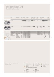
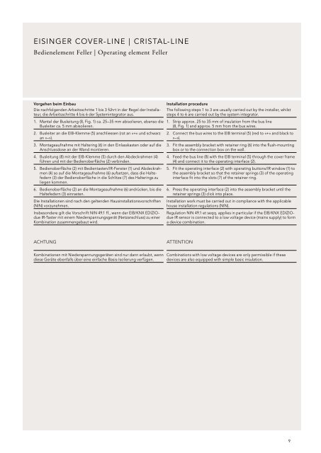
eisingeR COveR-line | CRistal-line<br />
Bedienelement Feller | Operating element Feller<br />
Vorgehen beim Einbau<br />
Die nachfolgenden Arbeitsschritte 1 bis 3 führt in der Regel der Installateur,<br />
die Arbeitsschritte 4 bis 6 der Systemintegrator aus.<br />
1. Mantel der Busleitung (8, Fig. 1) ca. 25–35 mm abisolieren, ebenso die<br />
Busleiter ca. 5 mm abisolieren.<br />
2. Busleiter an die EIB-Klemme (5) anschliessen (rot an «+» und schwarz<br />
an «–»).<br />
3. Montageaufnahme mit Haltering (6) in den Einlasskasten oder auf die<br />
Anschlussdose an der Wand montieren.<br />
4. Busleitung (8) mit der EIB-Klemme (5) durch den Abdeckrahmen (4)<br />
führen und mit der Bedienoberfläche (2) verbinden.<br />
5. Bedienoberfläche (2) mit Bedientasten/IR-Fenster (1) und Abdeckrahmen<br />
(4) so auf die Montageaufnahme (6) aufsetzen, dass die Haltefedern<br />
(3) der Bedienoberfläche in die Schlitze (7) des Halterings zu<br />
liegen kommen.<br />
6. Bedienoberfläche (2) an die Montageaufnahme (6) andrücken, bis die<br />
haltefedern (3) einrasten.<br />
Die Installationen sind nach den geltenden Hausinstallationsvorschriften<br />
(NIN) vorzunehmen.<br />
Insbesondere gilt die Vorschrift NIN 49.1 ff., wenn der EIB/KNX EDIZIOdue<br />
IR-Taster mit einem Niederspannungsgerät (Netzanschluss) zu einer<br />
Kombination zusammengebaut wird.<br />
ACHTUNG<br />
Kombinationen mit Niederspannungsgeräten sind nur dann erlaubt, wenn<br />
diese Geräte ebenfalls über eine einfache Basis-Isolierung verfügen.<br />
Installation procedure<br />
The following steps 1 to 3 are usually carried out by the installer, whilst<br />
steps 4 to 6 are carried out by the system integrator.<br />
1. Strip approx. 25 to 35 mm of insulation from the bus line<br />
(8, Fig. 1) and approx. 5 mm from the bus wires.<br />
2. Connect the bus wires to the EIB terminal (5) (red to «+» and black to<br />
«–»).<br />
3. Fit the assembly bracket with retainer ring (6) into the flush-mounting<br />
box or to the connection box on the wall.<br />
4. Feed the bus line (8) with the EIB terminal (5) through the cover frame<br />
(4) and connect it to the operating interface (2).<br />
5. Fit the operating interface (2) with operating buttons/IR window (1) to<br />
the assembly bracket so that the retainer springs (3) of the operating<br />
interface fit into the slots (7) of the retainer ring.<br />
6. Press the operating interface (2) into the assembly bracket until the<br />
retainer springs (3) click into place.<br />
Installation work must be carried out in compliance with the applicable<br />
house installation regulations (NIN).<br />
Regulation NIN 49.1 et seqq. applies in particular if the EIB/KNX EDIZIOdue<br />
IR sensor is connected to a low voltage device (mains supply) to form<br />
a device combination.<br />
ATTENTION<br />
Combinations with low voltage devices are only permissible if these<br />
devices are also equipped with simple basic insulation.<br />
9