Montageanleitung Trennfunkenstrecken EXFS L 100 ... - EuroVolt
Montageanleitung Trennfunkenstrecken EXFS L 100 ... - EuroVolt
Montageanleitung Trennfunkenstrecken EXFS L 100 ... - EuroVolt
- Keine Tags gefunden...

Erfolgreiche ePaper selbst erstellen
Machen Sie aus Ihren PDF Publikationen ein blätterbares Flipbook mit unserer einzigartigen Google optimierten e-Paper Software.
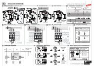
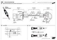
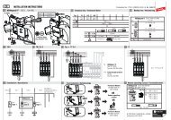
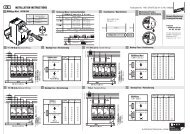
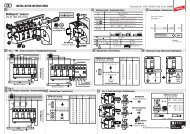
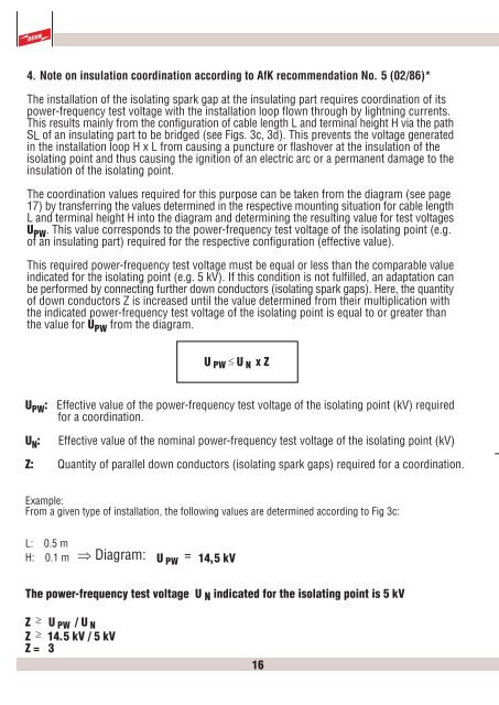
4. Note on insulation coordination according to AfK recommendation No. 5 (02/86)*The installation of the isolating spark gap at the insulating part requires coordination of itspower-frequency test voltage with the installation loop flown through by lightning currents.This results mainly from the configuration of cable length L and terminal height H via the pathSL of an insulating part to be bridged (see Figs. 3c, 3d). This prevents the voltage generatedin the installation loop H x L from causing a puncture or flashover at the insulation of theisolating point and thus causing the ignition of an electric arc or a permanent damage to theinsulation of the isolating point.The coordination values required for this purpose can be taken from the diagram (see page17) by transferring the values determined in the respective mounting situation for cable lengthL and terminal height H into the diagram and determining the resulting value for test voltagesU PW . This value corresponds to the power-frequency test voltage of the isolating point (e.g.of an insulating part) required for the respective configuration (effective value).This required power-frequency test voltage must be equal or less than the comparable valueindicated for the isolating point (e.g. 5 kV). If this condition is not fulfilled, an adaptation canbe performed by connecting further down conductors (isolating spark gaps). Here, the quantityof down conductors Z is increased until the value determined from their multiplication withthe indicated power-frequency test voltage of the isolating point is equal to or greater thanthe value for U PW from the diagram.U PW £ U N x ZU PW : Effective value of the power-frequency test voltage of the isolating point (kV) requiredfor a coordination.U N : Effective value of the nominal power-frequency test voltage of the isolating point (kV)Z: Quantity of parallel down conductors (isolating spark gaps) required for a coordination.Example:From a given type of installation, the following values are determined according to Fig 3c:L: 0.5 mH: 0.1 m Þ Diagram: U PW= 14,5 kVThe power-frequency test voltage U N indicated for the isolating point is 5 kVZ ³ U PW / U NZ ³ 14.5 kV / 5 kVZ = 316