Ditec Traffic C - Traffic CM - DITEC ENTREMATIC
Ditec Traffic C - Traffic CM - DITEC ENTREMATIC
Ditec Traffic C - Traffic CM - DITEC ENTREMATIC
- Keine Tags gefunden...

Sie wollen auch ein ePaper? Erhöhen Sie die Reichweite Ihrer Titel.
YUMPU macht aus Druck-PDFs automatisch weboptimierte ePaper, die Google liebt.
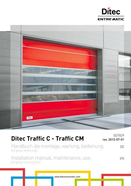
<strong>Ditec</strong> <strong>Traffic</strong> C - <strong>Traffic</strong> <strong>CM</strong>Handbuch die montage, wartung, bedienung.(Original Anleitung)Installation manual, maintenance, use.(Original instructions)0DT829rev. 2013-07-01DEENwww.ditecentrematic.com
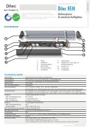
INHALTSVERZEICHNISKap. Inhalt ...........................................................................................................................................S.1. ALLGEMEINE SICHERHEITSHINWEISE ................................................................................... 22. TECHNISCH MERKMALE ........................................................................................................... 33. MECHANISCHE INSTALLATION3.1 Anfängliche Überprüfungen..................................................................................................... 43.2 Befestigung der Seitenpfosten................................................................................................. 43.3 Montage des Querbalkens ...................................................................................................... 43.4 Vorbereitung des Querbalkens ............................................................................................... 43.5 Montage des Torbehangs........................................................................................................ 43.6 Montage der Gegengewichte .................................................................................................. 43.7 Montage des Notstopp-Entriegelungshebels (Extra)............................................................... 43.8 Einbau der Lichtschranken...................................................................................................... 43.9 Einbau der Kontaktleiste.......................................................................................................... 44. ELEKTRISCHE ANSCHLÜSSE4.1 Elektrischer Schaltschrank....................................................................................................... 54.2 Anschlüsse Schaltkasten / Motor / Schutzvorrichtungen......................................................... 54.3 Sicherheits-Lichtschranken...................................................................................................... 55. ELEKTRONISCHE SCHALTTAFEL5.1 49E - anschlüsse..................................................................................................................... 65.2 47E (inverter) - anschlüsse.................................................................................................... 106. einstellungen UND START6.1 Überprüfung der Bewegungsrichtung ................................................................................... 146.2 Einstellung der verdrahteten Kontaktleiste............................................................................ 147. STÖRUNGSSUCHE.................................................................................................................... 158. WARTUNGSPLAN...................................................................................................................... 161. ALLGEMEINE SICHERHEITSHINWEISEDas vorliegende installationshandbuch ist ausschliesslich für das Fachpersonal bestimmt.Montage, elektrische Anschlüsse und Regelungen sind auf der Grundlage der bestehenden Vorschriften nache denRegeln der Technik auszüfuhren. Vor Einbaubeginn sind die Anweisungen sorgfältig durchzulesen. Falcher Einbaukann Gefahr mit sich bringen Das Verpackungsmaterial (Kunststoff, Polystyrol usw.) ist vorschriftsmäßig zu entsorgen. Esist von Kindern fernzuhalten, da es eine Gefahr für si bedeutet.Vor Beginn der Montage ist der einwandfreie Zustand des Produkts zu überprüfen. In explosionsgefährdeten Bereichen darfdas Produkt nicht eingebaut werden: Entzündbare Gase oder Rauch stellen eine ernsthafte Sicherheitsgefährdung dar.Um die vorgeschriebenen Sicherheitsabstände zu schaffen und Quetsch- Scher- Einzieh- und sonstige Gefahrbereichezu vermeiden bzw. abzutrennen, sind vor Montagebeginn die notwendigen baulichen Veränderungen vorzunehmen. Es istsicherzustellen, daß die tregende Struktur die erforderlichen Voraussetzungen an Festigkeit und Stäbilität erfüllt.Der Hesteller des Antriebs haftet nicht, wenn die Torrahmen oder -pfosten, die für den Antrieb vorgesehen sind, nichtordnungsgemäß und fachgerecht erstellen sind; er haftet ebenfalls nicht für Verformungen im Betrieb.Die Sicherheitseinrichtungen (Photozellen, Lichtschranken, Nothalteinrichtungen usw.) sind nach den Regeln der Technik sozu installieren, daß die geltenden Vorschriften und Richtlinien eingehalten sowie Einbauort, Betriebsweise des Antriebssystemsund die Kräfte, die das Tor beim Antrieb aufweist, berücksichtigt werden.Die Sicherheitseinrichtungen dienen dem Schutz vor Quetsch-, Scher-, Einzieh- und sonstigen Gefahrbereichen des Tors nachMontage des Antriebs. Zur Erkennung der Gefahrenbereichen sind die vorgeschiebenen Hinweisschilder anzubringen.Bei jeder Anlage sind die technischen Daten des Torantriebs gut sichtbar anzubringen. Vor dem Netzanschluß ist sicherzustellen,daß die Daten auf dem Typenschild mit denen des Stromversorgungsnetzes übereinstimmen.Netzsetig ist ein Allpoll-Schalter bzw. -Trennschalter mit Abstand der Kontakte in geöffneter Stellung > oder = 3 mmvorzusehen. Es ist sicherzustellen, daß der Elektroanlage die erforderlichen FI-Schalter und Überstromschutzschaltervorgeschaltet sind. Der Torantrieb ist an eine ordnungsgemäße Erdung, die nach den geltenden Sicherheitsvorschriftenausgeführ ist, anzuschließen. Der Hersteller des Antriebs lehnt jede Verantwortung ab, wenn beim Einbau Teile montiert werden,die weder den Sicherheitsanforderungen noch einem ordungsgemäßen Betrieb entsprechen. Bei Reparatur und Austausch sindausschließlich Originalersatzteile <strong>Ditec</strong> Entrematic zu verwenden. Der Einbaubetrieb ist verpflichtet, dem Benutzer alle notwendigenInformationen für Automatik-, Hand- und Notbetrieb des Torantriebs zu liefern und ihm die Betriebanleitung auszuhändigen.OptionszubehörCSafety ConfortTSafety TopAlle Rechte vorbehaltenDie wiedergegebenen Daten wurden mit höchster Sorgfalt zusammengestellt und überprüft. Es kann jedoch keinerleiVerantwortung für eventuelle Fehler, Auslassungen oder Näherungen, die technischen oder graphischen Notwendigkeitenzuzuschreiben sind, übernommen werden.0DT829 2013-07-01- 2 -
3. MECHANISCHE INSTALLATIONSiehe die entsprechenden Zeichnungen für die mechanische Installation auf Seite 22 - 23 (das mittlere Blatt lässtsich herausnehmen)3.1 Anfängliche Überprüfungen (Abb.1)• Die Abmessungen der Öffnung mit den Tormaßen vergleichen. Bei Installation in der lichten Durchgangsbreite dieerforderlichen Toleranzen berücksichtigen. Prüfen, ob mögliche Hindernisse die Montage behindern.• Sicherstellen, dass die Auflageflächen vollkommen eben sind. Gegebenenfalls mit geeigneten Passscheiben ausgleichen.• Die Strukturbeschaffenheit der Wandöffnung überprüfen: die sichere Verankerung mittels Bügel oder Dübel mussgewährleistet sein. Sollte die Konsistenz ungenügend oder zweifelhaft sein, muss eine entsprechende selbsttragendeMetallstruktur angefertigt werden.3.2 Befestigung der Seitenpfosten (Abb.2)• Den gesamten Platzbedarf des Querbalkens (LT) messen und die Position der Seitenpfosten markieren.• Die Abdeckungen der Pfosten entfernen und die Sockeln der Pfosten an den gekennzeichneten Stellen mit Dübeln derGröße M8 befestigen (Abb.4).• Die Seitenpfosten ins Lot bringen und laut Bezug (A) bei Außenbügeln oder laut Bezug (B) bei Befestigung auf derInnenseite der Stütze befestigen. Dübelgröße M8. Die Diagonalen prüfen.Den Seitenpfosten auf Höhe des Gleitbereichs des Gegengewichtes (C) nicht anbohren.3.3 Montage des Querbalkens• Die an den Enden des Querbalkens vormontierten Bolzen M8 entfernen.• Den Querträger mit entsprechendem Hebezeug heben.• Den Querbalken auf den Seitenpfosten auflegen, die Befestigungsbolzen wieder einsetzen und festziehen (Abb.3).• Bei Toren mit PL > 4000 wird empfohlen, den Querbalken in der Mitte zu befestigen (um eine unschöne Verbiegung derKonstruktion zu vermeiden).3.4 Vorbereitung des Querbalkens• Unter Bezugnahme auf die (Abb.5A-5B-5C) das Vorgelegerad des Riemens je nach Position des Torbehangs positionieren.Die Standardposition wird in (Abb.5A) gezeigt.• Sollte das Vorgelegerad des Riemens nicht in der Position wie in “5A” gezeigt gehalten werden können, das Rad durchAusschrauben des Bolzens M8 entfernen und das Vorgelegerad des Riemens in der gewünschten Position neu montieren.Nach der Befestigung prüfen, ob sich das Rad frei dreht. Den Vorgang für jede Halterung wiederholen3.5 Montage des Torbehangs• Den Torbehang in die Seitenpfosten einsetzen und anheben, dabei prüfen, ob die Riemenringe richtig positioniert sind.• Mithilfe der beigepackten Bolzen M8 die Verbindungsmuffe des Torbehangs am Querbalken befestigen (Abb.6).• Den Torbehang vorsichtig ganz herunterlassen. Bei <strong>Ditec</strong> <strong>Traffic</strong> C mit modularem Torbehang: ggf. die Länge des Torbehangsregulieren, indem der Behang um das Kupplungsrohr gewickelt wird.• Die Heberiemen des Torbehangs abrollen. Sicherstellen, dass noch mindestens 2 Umdrehungen auf der Wickeltrommelbleiben. (Abb.9)• Die Riemen durch die bereits entlang des Torbehangs vorbereiteten Riemenringe ziehen. (Abb.7)• Die Riemenenden mithilfe der am 1. Rohr angebrachten Bügeln befestigen. (Abb.7)• Die Rohre mit den Plastikschalen befestigen, damit sie seitlich nicht verrutschen können (Abb.8) am 1. Rohr sind die Schalenbereits befestigt.3.6 Montage der Gegengewichte• Das Gegengewicht mit einem geeigneten Hebezeug (Stapler) anheben.• Die Riemen abrollen und um die Vorgelegescheiben legen. Den Riemen um den oberen Bolzen fädeln und mit derentsprechenden Platte arretieren, dabei das Gegengewicht ca. 200 mm vom oberen Endanschlag entfernt halten. (Abb.9)• Mithilfe der 4 unteren Elemente des Gegengewichts die Feineinstellung der Ausbalancierung durchführen. (Abb.9)3.7 Montage des Notstopp-Entriegelungshebels (Extra)• Der Notstopp-Entriegelungshebel muss in einem Abstand von mindestens 1,8 m zum Boden montiert werden (Abb.10, 11).• Die Antriebslitze in den Zwischenräumen verstauen und mit der Bremse des Getriebemotors verbinden (Abb.12, 13).• Die Funktionstüchtigkeit der Vorrichtung prüfen; bei Betätigen des Hebels muss sich der Torbehang ungehindert heben.• Bei <strong>Ditec</strong> <strong>Traffic</strong> <strong>CM</strong> mit doppeltem Motor sind die Entriegelungen mithilfe der Vorrichtung aus “Abb. 14” verbunden.3.8 Einbau der Lichtschranken• Die Behälter an der Stütze montieren (Abb.15). Für die Anschlüsse die in der Verpackung der Lichtschranken enthalteneBedienungsanleitung verwenden.3.9 Einbau der Kontaktleiste• Den Torbehang auf ca. 1 m Höhe positionieren.• Die Kontaktleiste in die untere Tasche des Torbehangs (Abb.16) einsetzen.• Die Leiste über die gesamte Länge des Torbehangs gleiten lassen und genau mittig zum Torbehangs ausrichten.0DT829 2013-07-01- 4 -
4. ELEKTRISCHE ANSCHLÜSSEDE4.1 Elektrischer Schaltschrank• Die Kabel mit vorverkabelten Klemmleisten in den Behälter einführen und an die Karten anschließen (Abb.17). Kabel inden Kabelkanal einführen und auf dem Motor vorgesehene Steckverbinder anschließen (Abb.18).4.2 Anschlüsse Schaltkasten / Motor / Schutzvorrichtungen• In Schema 19 werden die gelieferten Verkabelungen und ihre Position im Tor angegeben; jede Verkabelung wird durcheine eigene Bezeichnung auf einem Aufkleber kenntlich gemacht.4.3 Sicherheits-Lichtschranken• Die torseitigen Anschlüsse wie in (Abb.19) angegeben vornehmen.• Die Anschlüsse im Schaltkasten gemäß den Schaltplänen durchführen171819A935G/E7825A - CA933A - 7823BA931C - 7824BA935LA451LA934E/L0 1SchwarzBlauOrangeRotRx2Tx20 1SchwarzBlau798279820 1C T0 1SchwarzBlauTx1Rx1SchwarzBlauOrangeRot7825A7823A7824A7824A7823C/D7824C/D7824C/DA935E/F- 5 - 0DT829 2013-07-01
49E5.1 ELEKTRONISCHE SCHALTTAFEL 49E - AnschlüsseEingangCommande Funktion Beschreibung1 2 N.O Automatische Die permanente Schließung des Kontaktes aktiviert die automatische Öffnung.Schließung1 3 N.O Öffnung Bei DIP1=ON wird beim Schließen des Kontaktes eine Öffnung ausgelöst.Schrittbetrieb Bei DIP1=OFF wird beim Schließen des Kontaktes eine Öffnung oder Schließungin folgender Reihenfolge ausgelöst: Öffnet-Stopp-Schließt-Öffnet.Anm.: Ist die automatische Schließung aktiviert, ist der Stopp nicht von Dauer,sondern hat die von TC eingegebene Dauer.1 4 N.O Schließung Die Schließung des Kontakts aktiviert den Schließvorgang.1 6 N.G Umkehrsicherheit Die Öffnung des Sicherheitskontaktes verursacht die Bewegungsumkehr(erneute Öffnung) während der Schließphase.41 8 N.G Umkehrsicherheit Die Öffnung des Sicherheitskontaktes verursacht die Bewegungsumkehr(erneute Öffnung) während der Schließphase.1 9 N.G Stopp Die Öffnung des Sicherheitskontaktes verursacht das Anhalten der Bewegung.1 9 N.O Mit nicht impulsivemBefehlDie permanente Öffnung des Sicherheitskontaktes aktiviert die Funktion mitnicht impulsivem Befehl.Unter dieser Bedingung funktionieren die Öffnungs- (1-3/1-20) und Schließbefehle(1-4) nur, wenn sie gedrückt gehalten werden. Werden sie losgelassen, kommtder Antrieb zum Stillstand. Die eventuell vorhandenen Sicherheiten, der Befehlfür den Schrittbetrieb und die automatische Schließung sind deaktiviert.1 20 N.O Teilöffnung Die aktive Schließung des Kontaktes aktiviert Einen teilweisen Öffnungsvorgangmit der über den Trimmer RP eingestellten Dauer. Bei stillstehendem Antrieb führtder Befehl für eine teilweise Öffnung den Vorgang durch, der entgegengesetztzu dem ist, das dem Stillstand vorausgegangen ist.0 11 N.G EndschalterSchließenDie Öffnung des Endschalterkontaktes stoppt die Schließbewegung.0 12 N.G Endschalter Öffnen Die Öffnung des Endschalterkontaktes stoppt die Öffnungsbewegung.0 17 Nicht verwenden Den Eingang frei lassenFunktion mit nicht impulsivem BefehlFunktion mit impulsivem Befehl17 14 12 11 0 0 0 1 1 2 3 4 6 8 9 20 4117 14 12 11 0 0 0 1 1 2 3 4 6 8 9 20 41AusgängeKarte Ausgang Wert BeschreibungEL07L1 +0 –0 1424 V= / 0,5 A24V= / 50 W(2 A)Stromversorgung des Zubehörs.Ausgang für Stromversorgung der externen Zubehörgeräteeinschließlich Statuslampen.Blinkend (LAMPH).Schaltet sich während des Öffnungs- und Schließvorgangs ein.- LK + 24 V= / 0,5 A Ausgang ist während der Türbewegung aktiv.EL07PW1U W VM3 ~400 V~ / 4 ADreiphasenmotor.Anm.: Wenn die Drehung des Motors nicht der korrektenLaufrichtung entspricht, die Speisephasen U - W umkehren.0DT829 2013-07-01- 6 -
49EDELSMLKCOMEL07L00000000000www.ditec.it41 1IN1FUSEF4EL07PW100000000000LSA<strong>CM</strong>LKJ71394LDVLDR20SOEOPRGU W VRP TCONON- LK +1 2 3 4 5 6OUT111 12 17 IN SA POWERNIO17 14 12 11 0 0 0 1 1 2 3 4 6 8 9 20 41A933A - 7823BRotWeißBraunOrangeSchwarzBlauSchwarzBlauRotOrangeWeißBraunL3 L2 L1SchwarzBlauOrangeRot7825A-CTVom Installateurfertigzustellender AnschlussA935LA935G / EBraunBlauSchwarzBlauOrangeRot0 1RX2TX20 1A451LA934E/L01SOFSOF01SchwarzBlauOrangeRotTSchwarzBlau0 1TX1TRX10 1BlauSchwarzTRotOrangeBlauSchwarz10161079827982A931C - 7824B17 14 12 11 0 0 0 1 1 2 3 4 6 8 9 20 41CVorverkabelterStandardanschlussSchwarzBlauOrangeRotBraunWeißOrangeRotBlauSchwarz7825A-CA935CA935G / EBraunBlauSchwarzBlauOrangeRot0 1RX2TX20 1A451LA934E/L0184101SchwarzBlauOrangeRotCSchwarzBlau0 1TX1CRX10 1BlauSchwarzCRotOrangeBlauSchwarz10161079827982- 7 - 0DT829 2013-07-01
49EREGOLAZIONI EINSTELLUNGEN E SEGNALAZIONIUND ANZEIGENTCTrimmer0 s 30 sBeschreibungZeiteinstellung der automatischen Schließung. Von 0 bis 30 s.Anm.: Nach der Aktivierung des Stoppbefehls und nach dem erneuten Schließen des Kontaktes1-9 schaltet sich die automatische Schließung erst nach einem Befehl für die totale Öffnung, dieteilweise Öffnung oder die Öffnung im Schrittbetrieb ein.RP Einstellung teilweise Öffnung Motor. Von 0 bis 30 s.0 s 30 sFür <strong>Ditec</strong> <strong>Traffic</strong>die Dip-switchwie folgtpositionieren:ON1 2 3 4 5 6Dip-switch Beschreibung OFF ONDIP 1 Funktion Befehl 1-3. Schrittbetrieb. Öffnung.DIP 2DIP 3Verlängerung Zeitautomatische Schließung.3 Sekunden langesVorblinken.Nicht verwenden. 100 %Bei Öffnung deaktiviert.Nur beiDIP 4 Anwendungstypologie. Nicht verwenden. Flexibles Tor.Sowohl bei Öffnung als auchbei Schließung aktiviert.DIP 5 Dynamische Bremse. Deaktiviert. Nicht verwenden.DIP 6 Doppelgeschwindigkeit Deaktiviert. Nicht verwenden.Brücken Beschreibung OFF ONSO Betrieb mitBewegungsumkehr.Bei stillstehendem Antrieb und wenn dieKontakte 41-8 offen sind, ist es möglich,den Öffnungsvorgang zu aktivieren.EO Elektrobremse. Nicht verwenden. Normal.LED Leuchtet BlinktPOWER Stromversorgung vorhanden 24 V=. /SAIN111217Zeigt an, dass mindestens einer derSicherheitskontakte geöffnet ist.( 6 - 8 - 9 )Schaltet sich bei jedem Befehl und bei jederVeränderung an Dip-switch und Drahtbrücke ein.Gibt an, dass der Kontakt desSchließendschalters belegt ist 0-11 ist offen.Gibt an, dass der Kontakt desÖffnungsendschalters belegt ist 0-12 ist offen.Zeigt an, dass der Kontakt des Endschalters0-17 geöffnet ist. (nicht verwenden)Bei stillstehendem Antrieb und wenndie Kontakte 41-8 offen sind, werdenjegliche Vorgänge verhindert.- Zeigt die über die Druckschaltertafel PT4 (wenn vorhanden)aktivierte STOP-Funktion an.- Bei Verwendung der Befehlseinrichtung SOFA1-SOFA2 zeigtsie das Misslingen des Sicherheitstests an (Klemme 41).- Beim Einschalten blinkt die LED und zeigt die Zählung derdurchgeführten Manöver an:Jedes schnelle Blinken = 10000 VorgängeJedes langsame Blinken = 100000 Vorgänge////ONTasteLöst den Öffnungsvorgang aus.Löst den teilweisen Öffnungsvorgangaus.Aktiviert und deaktiviert die STOPP-Funktion.Löst den Schließvorgang aus.LEDAnm.: Die eingeschaltete grüne LED signalisiert das Vorhandensein von24 V= Versorgung.Anm.: Die eingeschaltete rote LED signalisiert die Aktivierung des STOPPs.Die blinkende rote LED signalisiert die Aktivierung der Schutzvorrichtungen.0DT829 2013-07-01- 8 -
49EDEONEL07L00000000000www.ditec.itFUSEF4EL07PW100000000000COM1394LDVLDR20RP TCSOONEOONPRGU W V- LK +1 2 3 4 5 611 12 17 IN SA POWERNIO17 14 12 11 0 0 0 1 1 2 3 4 6 8 9 20 41L3 L2 L1F1F2F3SICHERUNGENID Werte Größe SchaltkreisF1 - F2 - F3 8A - 500V 10.3 x 38 DreiphasenleitungF4 3.15A - 230V 5 x 20 TransformatorEinstellung Endschalter1. Tor bewegen durch drücken der entsprechenden Tasten, undBewegungsrichtung überprüfen und nötigenfalls Bewegungsrichtungdurch Änderung der Phasensequenz korrigieren. Dazu werden 2 Phasenvertauscht.2. Den Torbehang in die Schließstellung bringen.3. Den Torbehang in Position Tor geschlossen bringen und mit einemSchraubenzieher den Nocken "C" soweit drehen, bis der entsprechendeMikroschalter reagiert.4. Mit Öffnungsendschalter analog vorgehen: Torbehang in Position Toroffen bringen und Nocken “A” einstellen.5. Einstellung durch Inbetriebnahme des Antriebs überprüfen undnötigenfalls eine feine Nacheichung vornehmen.CAAC- 9 - 0DT829 2013-07-01
47E5.2 ELEKTRONISCHE SCHALTTAFEL 47E (INVERTER) - AnschlüsseEingangBefehl Funktion Beschreibung1 2 N.O AutomatischeSchließungDie permanente Schließung des Kontaktes aktiviert die automatischeÖffnung.1 3 N.O Öffnung Wird beim Schließen des Kontaktes eine Öffnung ausgelöst.1 4 N.O Schließung Die Schließung des Kontakts aktiviert den Schließvorgang.41 40 N.G Umkehrsicherheit Die Öffnung des Sicherheitskontaktes verursacht die Bewegungsumkehr(erneute Öffnung) während der Schließphase.1 8 N.G Umkehrsicherheit Die Öffnung des Sicherheitskontaktes verursacht die Bewegungsumkehr(erneute Öffnung) während der Schließphase.1 9 N.G Stop Die Öffnung des Sicherheitskontaktes verursacht das Anhalten derBewegung.1 9 N.O Mit nicht impulsivemBefehlDie permanente Öffnung des Sicherheitskontaktes aktiviert die Funktionmit nicht impulsivem Befehl.Unter dieser Bedingung funktionieren die Öffnungs- (1-3/1-20) undSchließbefehle (1-4) nur, wenn sie gedrückt gehalten werden. Werden sielosgelassen, kommt der Antrieb zum Stillstand. Die eventuell vorhandenenSchutzvorrichtungen, der Befehl für den Schrittbetrieb und die automatischeSchließung sind deaktiviert.1 20 N.O Teilöffnung Die aktive Schließung des Kontaktes aktiviert einen teilweisesÖffnungsvorgang mit der über den Trimmer RP eingestellten Dauer.1 11 N.G EndschalterSchließenDie Öffnung des Endschalterkontaktes stoppt die Schließbewegung.1 12 N.G EndschalterVerzögerungDie Öffnung des Endanschlagkontaktes aktiviert die Verlangsamung derÖffnung1 13 N.G Endschalter Öffnen Die Öffnung des Endschalterkontaktes stoppt die Öffnungsbewegung.AusgängeAusgang Wert Beschreibung1 +0 -24 V= / 0,5 AStromversorgung des Zubehörs.Ausgang für Stromversorgung der externen Zubehörgeräte einschließlichStatuslampen.LAMP230 V~ / 50 WBlinkend (LAMP).Schaltet sich während des Öffnungs- und Schließvorgangs ein.CNTAktivierung des ImpulszählersWird bei jedem Schließmanöver aktiviert.-F +F 24 V= / 0,5 AElektrobremse Motor.Ist der Ausgang für die gesamte Dauer der Bewegung sowohl bei der Öffnung alsauch bei der Schließung aktiv.U W VM3 ~230 V~ / 6 A Dreiphasenmotor.0DT829 2013-07-01- 10 -
47ECNT+F -F U V WDE1716LSMLK1LSAB<strong>CM</strong>LKP 2.0IN 11 4 1 I N 1OUT1U24J215ONOFF 1 2 3 4131412T5T3T1T6T4T2GNDL NA933A - 7823BWeißRotBlauSchwarzBraunOrangeP O W E RSOFA1J111 10 9 8 7 6 5 4 3 2 11 11 12 13DL41 40 20 9 8 4 3 2 1 1 0 LAMPF1 F2230 V 50/60 HzTVom Installateurfertigzustellender AnschlussBraunWeißOrangeRotBlauSchwarzSchwarzBlauOrangeRot7825A-CA935LA935G / EBraunBlauSchwarzBlauOrangeRotA451LA934E/L01SOFSOF01SchwarzBlauOrangeRotTSchwarzBlau0 10 1RX2TX1TTX2RX10 10 1Blau 1Schwarz 0TRotOrangeBlauSchwarz181079827982A931C - 7824BCVorverkabelterStandardanschluss1 11 12 1341 40 20 9 8 4 3 2 1 1 0 LAMPSchwarzBlauOrangeRotSchwarzBlauRotOrangeWeißBraun7825A-CA935LA935G / EBraunBlauSchwarzBlauOrangeRotA451LA934E/L01404101SchwarzBlauOrangeRotCSchwarzBlau0 10 1RX2TX1CTX2RX10 10 1BlauSchwarzCRotOrangeBlauSchwarz10181079827982- 11 - 0DT829 2013-07-01
47EEINSTELLUNGEN UND ANZEIGENTrimmerBeschreibungT1 Zeiteinstellung der automatischen Schließung. Von 0 bis 30 s.0 s 30 sT2 Einstellung teilweise Öffnung. Von 0 bis 10 s.0 s 10 sT30 MAXEinstellung der Öffnungsgeschwindigkeit.T40 MAXEinstellung der Schließgeschwindigkeit.T50 MAXEinstellung der Öffnungsverzögerung.T60 MAXEinstellung der Schließverzögerung.Dip-switch Beschreibung OFF ONDIP 1 Aktiviert Trimmer Einstellung Deaktiviert AktiviertDIP 2 Vorblinken bei Öffnung Deaktiviert AktiviertDIP 3 Zukünftiger Gebrauch Nicht verwenden Nicht verwendenDIP 4 Zukünftiger Gebrauch Nicht verwenden Nicht verwendenJ2 Bremse Nicht durchtrennen Bremse 24 VLED Input LeuchtetDL1 (2) Automatisches SchließenDL2 (3) ÖffnenDL3 (4) SchließenDL4 (9) StoppDL5 (20) TeilöffnungDL6 (40) SchließkantensicherheitDL7Stop-TasterDL8 (8) UmkehrsicherheitDL9 (13) Endschalter ÖffnenLED Input LeuchtetDL10 (12) Endschalter VerzögerungDL11 (11) Endschalter SchließenDL12BlinkenDL13BetriebsanzeigeDL14StörungDL15SelbstestDL16BremseDL17ZählerTasteLEDONLöst den Öffnungsvorgang aus.Löst den teilweisen Öffnungsvorgangaus.Aktiviert und deaktiviert die STOPP-Funktion.Löst den Schließvorgang aus.Anm.: Die eingeschaltete grüne LED signalisiert das Vorhandensein von24 V= Versorgung.Anm.: Die eingeschaltete rote LED signalisiert die Aktivierung des STOPPs.Die blinkende rote LED signalisiert die Aktivierung der Schutzvorrichtungen.0DT829 2013-07-01- 12 -
47ECNT+F -F U V WDE1716ON1GNDU24J215ONOFF 1 2 3 4131412T5T3T1T6T4T2LNJ111 10 9 8 7 6 5 4 3 2 1DLF1F21 11 12 1341 40 20 9 8 4 3 2 1 1 0 LAMP230 V 50/60 HzSICHERUNGENID Werte Größe SchaltkreisF1 - F2 12A - 500V 10.3 x 38 EinphasenleitungEinstellung Endschalter1. Verzögerungsrampen auf Null einstellen. (T5 - T6)2. Den Endschalter (C) auf dem Getriebemotor so einstellen, dass das Tor ineiner Entfernung von ca. 200÷300 mm vor dem endgültigen Schließpunktanhält.3. Den Endschalter (A) auf dem Getriebemotor auf max. Öffnungspunkteinstellen.4. Den Verzögerungs-Schalter (B) so einstellen, dass er bei etwa ¾ derÖffnungsstrecke schaltet.5. Die Öffnungsgeschwindigkeit mittels Trimmer (T3) und dieSchließgeschwindigkeit mittels Trimmer (T4) einstellen.6. Die Trimmer der Verzögerungsrampen (T5 Öffnen) und (T6 Schließen) soeinstellen, dass der Behang in den endgültigen Positionen anhält.CBAC300B¾ASTÖRUNGSSUCHEBEFEHL PROBLEM ÜBERPRÜFUNGEin beliebiger Befehl injeder beliebigen Stellungdes TorbehangsÖffnungsbefehlWährend desSchließmanöversTorbehang und Motorbewegen sich nicht:Der Motor bewegt sichschleppend oder erreichtnicht die eingestellteGeschwindigkeit (dieMotorbremse wird nichtausgelöst)Der Motor führt dieBremsrampe nicht ausHINW.: für die allgemeine Diagnostik siehe auch Seite 15• Test der elektronischen Steuerung fehlgeschlagen (grüne LED13 ausgeschaltet und rote LED 14 eingeschaltet)• Überprüfen, ob die Drahtbrücke J2 not durchtrennt wurde• Einstellung des Endschließschalters (C) in einem Abstandzum Boden von ca. 300mm• Einstellung der Bremsrampe mittels Trimmer T6- 13 - 0DT829 2013-07-01
6. ÜBERPRÜFUNG UND START6.1 Uberprüfung der Bewegungsrichtung• Torbehang auf zirka die Hälfte der Höhe bringen.• Tor bewegen durch Drücken der entsprechenden Tasten, und Bewegungsrichtung überprüfen.• Nötigenfalls Bewegungsrichtung durch Änderung der Phasensequenz korrigieren. Dazu werden 2 Phasen vertauscht.6.2 Einstellung der Drahtrippe• Bis zum Eingreifen des Mikroschalters anschrauben, folglich um 1/2 Drehung lösen. Kontakt blockieren (abb. 20).200DT829 2013-07-01- 14 -
7. STÖRUNGSSUCHEDANGERBevor Arbeiten in den elektronischen Apparaturen vorgenommen werden, ist sicherzustellen, dass dieStromzufuhr unterbunden wurde.DEATTENTIONDie folgenden Anweisungen richten sich ausschließlich an qualifiziertes und befugtes Personal. Diespezifischen Gesetze und Normen müssen immer befolgt werden, auch wenn nicht ausdrücklich daraufhingewiesen wird.Für Reparaturen oder Austausch von Bauteilen immer nur <strong>Ditec</strong> Entrematic Originalteile verwenden.BEFEHL PROBLEM ÜBERPRÜFUNGEin beliebiger Befehl injeder beliebigen Stellungdes TorbehangsÖffnungsbefehl beigeschlossenemTorbehangSchließbefehl beigeöffnetem TorbehangAktivierung desStoppbefehls währendeines ManöversAktivierung einerSchutzvorrichtungwährend der SchließungAutomatische Schließungbei geöffnetem TorbehangaktivWährendManöverseinesTorbehang und Motorbewegen sich nichtDer Motor dreht sich in dieverkehrte RichtungDer Motor bewegt sichnichtDer Motor bewegt sichnichtDer Motor bleibt nichtstehenDer Motor kommt mitVerzögerung zumStillstandDie Torbewegung wirdnicht umgekehrtDie Motorbewegungkommt zum Stillstand(das Tor öffnet sich nichtwieder vollständig)Das Tor schließt sichnicht automatisch nachder über TC eingestelltenZeitDer Torbehang macht nichtam Endschalter haltDer Torbehang machtnicht regelmäßig amEndschalter halt• Stromversorgung oder Sicherungen F1, F2, F3• STOPP aktiviert (“Stopp”-LED am Tastenpult leuchtet starr)• Motor an falsche Klemmen angeschlossen u./o. Dip-switch infalscher Position (siehe Seite 8)• Öffnungsendschalter (A) und Schließendschalter (C) sindgleichzeitig aktiv (LED 11 und 12 leuchten)• Wärmeschutzschalter des Motors wurde ausgelöst (LED 11und 12 leuchten)• Eine der Leistungsvorrichtungen ist defekt (elektronischeSteuerung, Motor, Motoranschlusskabel)• Die Position von 2 Phasen der Stromversorgung umkehren• Öffnungsbefehl nicht richtig angeschlossen oder defekt (LEDIN schaltet sich bei Aktivierung des Befehls nicht ein)• Schutzvorrichtung wurde bei geschlossener Drahtbrücke SOausgelöst (LED der Stopptaste blinkt und LED SA leuchtet starr)• Öffnungsendschalter (A) aktiv (LED 12 leuchtet)• Schließbefehl immer aktiviert oder es liegt ein Kurzschlussvor (LED IN immer eingeschaltet)• Schließbefehl nicht richtig angeschlossen oder defekt (LEDIN schaltet sich bei Aktivierung des Befehls nicht ein)• Schutzvorrichtung wurde ausgelöst (LED der Stopptaste blinktund LED SA leuchtet starr)• Schließendschalter (C) aktiv (LED 11 leuchtet)• Öffnungsbefehl immer aktiviert oder es liegt ein Kurzschlussvor (LED IN immer eingeschaltet)• Selbsttest der Schutzvorrichtungen fehlgeschlagen (Stopp-LED am Tastenpult ausgeschaltet und LED SA blinkt)• Stoppbefehl nicht funktionstüchtig oder falsch angeschlossen(Stopp-LED am Tastenpult schaltet sich nicht ein und LED SAblinkt nicht)• Motorbremse abgenutzt oder defekt• Schutzvorrichtung defekt oder falsch angeschlossen (Stopp-LEDam Tastenpult blinkt nicht und LED SA schaltet sich nicht ein)• Eingang 17 geschlossen (LED 17 ausgeschaltet)• Befähigung zur automatischen Schließung (Anschluss 1-2)nicht korrekt ausgeführt• Öffnungsbefehl immer aktiviert oder ein Kurzschluss liegt vor(LED IN immer eingeschaltet)• Selbsttest der Schutzvorrichtungen fehlgeschlagen (Stopp-LED am Tastenpult ausgeschaltet und LED SA blinkt)• Kurzschluss am Kontakt des Endschalters (LED 11 oder LED 12immer ausgeschaltet)• Mechanischer Defekt am Endschalter (LED 11 oder LED 12 immerausgeschaltet)• Abnutzung oder Defekt an der Bremse (LED 11 oder LED 12eingeschaltet)• Dip-Schalter 5 auf OFF• Sicherung F5 durchgebranntHINW.: für die spezifische Diagnostik der Schalttafel mit Inverter 47E siehe auch Seite 13- 15 - 0DT829 2013-07-01
8. WARTUNGSPLAN (alle 6 Monate)Es empfiehlt sich regelmäßig Überprüfungen durch einen qualifizierten und befugten Techniker <strong>Ditec</strong> Entrematic entsprechendden nationalen Vorschriften und den Angaben in den Produktunterlagen vornehmen zu lassen. Die Anzahl der Wartungseingriffesollte in Übereinstimmung mit den nationalen Anforderungen und entsprechend den Angaben in den Produktunterlagenfestgelegt werden.Befestigung / Montage• Die Verbindungsschrauben zwischen Seitenpfosten und oberer Querhalterung anziehen• Die Verankerung des Tors im Durchgang überprüfenAntrieb• Die korrekte Befestigung des Motors prüfen• Die Straffung der Treibkette prüfen• Die Funktionstüchtigkeit der Endschalter und die korrekte Ausrichtung der Nocken prüfen.• Die Abnutzung der Bremsscheibe prüfen. Ggf. die Scheibe tauschen• Die Funktionstüchtigkeit der manuellen Bremsentriegelungsvorrichtung (falls vorgesehen) prüfenBehang-Wickelwelle / Riemen• Die Befestigung der Lagerhalterungen überprüfen• Die Lagerhalterungen schmieren• Die Abnutzung der Riemen des Gegengewichts und des Torbehangs prüfen. Ggf. die Riemen tauschenSicherheitsvorrichtungen• Die Funktionstüchtigkeit der Kontaktleiste prüfen• Den Zustand des Gummiprofils der Sicherheitsleiste (SOF) prüfen• Die Einstellung und den eventuellen Verschleiß des Kabels der elektromechanischen Leiste prüfen• Den Verschleiß des beweglichen Kabels der Leiste prüfen• Die Funktionstüchtigkeit der Lichtschranken prüfen8.1. WartungsplanDie folgende Tabelle zeigt die empfohlenen Intervalle, in Monaten, für den Austausch von Ersatzteilen während dervorbeugenden Wartung.Zyklen / StundeVerschleißanfälligeTeilCode
BedienungshandbuchDEALLGEMEINE SICHERHEITSHINWEISEDas vorliegende Handbuch ist integrierender und wesentlicher Bestandteil des Produkts und muß demselbenVerbraucher übergeben werden. Dieses Dokument muß aufgehoben und möglichen Stellvertretern fürden Gebrauch der Anlage übertragen werden. Die obengenannte Automation ist ein “Roll-als auch einPaketierungsmechanismus” und ist für den Gebrauch für den Sie ausdrücklich hergestellt wurde, bestimmt.Jeder andere Gebrauch wird als Mißbrauch angesehen und ist daher gefährlich. <strong>Ditec</strong> Entrematic lehnt jedeVerhaftung für Schäden, die wegen einem Mißbrauch entstanden sind, ab.GEBRAUCHSMAßNAHMEN• Während der Torbewgung nicht in die nähe des Wirkungsbereichs treten.• Bei Fehlfunktionen oder Störungen den Hauptschalter ausschalten. Die Wartungsarbeiten, sowie die Regelungsund Reparaturarbeiten müssen durch geschultes und dafür berechtigtem Personal durchgeführt werden• Jede Automation ist mit einem “Installations- und Wartungshandbuch” ausgestattet in dem auch dieInstandhaltung enthalten ist, vor allem ist es empfehlenswert, alle Sicherheitsvorrichtungen zu prüfen.DRUCKTASTEN• Totale Öffnung: der Drucktaste bewirkt eine totale Öffnung. Die Einstellung des Endanschlages ergibt sichdurch Endmikroschalter.• Teilöffnung: der öffnungsumfang vird zeitlich durch den Trimmer RP eingestellt.ABNEHMEN UND DEM BENUTZER AUSZUHANDINGEN• STOP: Bei betätigung wird das Tor gestoppt.• Schließung: der Drucktaste bewirkt eine totale Schließung. Die Einstellung des Endanschlages ergibt sichdurch Endmikroschalter.NOTENTRIEGELUNG ZUM MANUELLEN (Öffnen des Tores).Achtung: Bevor der Handgriff zur Notentriegelung gezogen wird.• Wird die Notentriegelung nicht betätigt so funktioniert die Motorbremse im Normalbetreib• Wird die Handentriegelung betätigt, so ist die Bremse vom Motor gelöst.Falls die Notentriegelung aufgrund eines Stromausfalls odereines Schadens betätigt werden muß, gehen Sie wie folgt vor:• Betätigen Sie die Hand-Notentriegelung (fig. 2) zum Lösen der Bremse.• Der Behang kann jetz ungebremst nach oben bewegt werden.• Wir die Notentriegelung nicht mehr betätigt (fig. 3) so ist die Bremse wieder aktiv.Stoppen Sie rechzeitig die Notöffnung, so daß der Behang vor erreichen der oberen Endlage gebremstwird, da ansonstendie Sicherheitsleiste gegen den Querträger prallen kann.<strong>Ditec</strong> S.p.A.Via Mons. Banfi, 321042 Caronno P.lla (VA) - ItalyTel. +39 02 963911 - Fax +39 02 9650314www.ditecentrematic.comInstaller:- 17 - 0DT829 2013-07-01
8. WARTUNGSPLAN (alle 6 Monate)Es empfiehlt sich regelmäßig Überprüfungen durch einen qualifizierten und befugten Techniker <strong>Ditec</strong> Entrematic entsprechendden nationalen Vorschriften und den Angaben in den Produktunterlagen vornehmen zu lassen. Die Anzahl der Wartungseingriffesollte in Übereinstimmung mit den nationalen Anforderungen und entsprechend den Angaben in den Produktunterlagenfestgelegt werden.Befestigung / Montage• Die Verbindungsschrauben zwischen Seitenpfosten und oberer Querhalterung anziehen• Die Verankerung des Tors im Durchgang überprüfenAntrieb• Die korrekte Befestigung des Motors prüfen• Die Straffung der Treibkette prüfen• Die Funktionstüchtigkeit der Endschalter und die korrekte Ausrichtung der Nocken prüfen.• Die Abnutzung der Bremsscheibe prüfen. Ggf. die Scheibe tauschen• Die Funktionstüchtigkeit der manuellen Bremsentriegelungsvorrichtung (falls vorgesehen) prüfenBehang-Wickelwelle / Riemen• Die Befestigung der Lagerhalterungen überprüfen• Die Lagerhalterungen schmieren• Die Abnutzung der Riemen des Gegengewichts und des Torbehangs prüfen. Ggf. die Riemen tauschenSicherheitsvorrichtungen• Die Funktionstüchtigkeit der Kontaktleiste prüfen• Den Zustand des Gummiprofils der Sicherheitsleiste (SOF) prüfen• Die Einstellung und den eventuellen Verschleiß des Kabels der elektromechanischen Leiste prüfen• Den Verschleiß des beweglichen Kabels der Leiste prüfen• Die Funktionstüchtigkeit der Lichtschranken prüfen8.1. WartungsplanDie folgende Tabelle zeigt die empfohlenen Intervalle, in Monaten, für den Austausch von Ersatzteilen während dervorbeugenden Wartung.Zyklen / StundeVerschleißanfälligeTeilCode
HINWEISE ZUM GEBRAUCHDEServiceklasse: 5 (Minimum 5 Betriebsjahre bei 600 Zyklen pro Tag)Verwendung: SEHR INTENSIV (für Zugang zu Industrie- und Gewerbebetrieben mit sehr intensiv Verwendung).• Die Betriebsklasse, die Betriebszeiten und die Anzahl aufeinanderfolgender Zyklen sind Richtwerte. Sie wurden mit Hilfestatistischer Verfahren unter normalen Betriebsbedingungen ermittelt und können im Einzelfall abweichen. Die Wertebeziehen sich auf den Zeitraum, in dem das Produkt funktionsfähig ist, ohne daß außerordentliche Wartungsarbeitenerforderlich sind.• Jede Automatikanlage weist veränderliche Faktoren auf: Reibung, Ausgleichvorgänge sowie Umweltbedingungen könnensowohl die Lebensdauer als auch die Qualität der Funktionweise der Automatikanlage oder einer ihrer Komponenten (wiez.B. die Automatiksysteme) grundlegend ändern. Es ist Aufgabe des Installationstechnikers, für die einzelne Situationentsprechende Sicherheitskoeffizienten vorzusehen.KonformitätserklärungWir, die Unterzeichneten:Entrematic Group ABLodjursgatan 10SE-261 44 LandskronaSchwedenerklären unter unserer Verantwortung, dass die Vorrichtung mit der Bezeichnung/Beschreibung:TRAFFC C - TRAFFIC <strong>CM</strong>Schnellfalttor mit Gegengewichtmit Leistungsstufen wie in der Leistungserklärung und am Produktaufkleber angegeben und mit Elektroantrieb wie imbeigepackten Installationshandbuch angegeben, den folgenden Richtlinien entspricht:2006/42/EC2004/108/E<strong>CM</strong>achinery Directive (MD)ElectroMagnetic Compatibility Directive (EMCD)Folgende harmonisierte europäische Normen kommen zur Anwendung:EN 13241-1 EN 61000-6-2 EN 61000-6-3 EN 60335-1 EN 60204-1Sonstige angewendete Normen oder technische Spezifikationen:EN 60335-2-103Die nachstehende benannte Stelle (für die komplette Anschrift kontaktieren Sie bitte die Entrematic Group AB) hat dieTyp-Prüfbescheinigung für die gegenständliche Vorrichtung ausgestellt:CSI Spa Reg. - N° 0497Bescheinigungsnummer: DE/051/05Der Produktionsprozess gewährleistet die Konformität der Vorrichtung mit der technischen Akte. Der Produktionsprozesswird regelmäßig durch Dritte geprüft.Verantwortlich für die technische Akte ist:Marco Pietro ZiniE-Mail: marco.zini@entrematic.comEntrematic Group ABLodjursgatan 10SE-261 44 LandskronaSchwedenOrt Datum Unterschrift FunktionLandskrona 2013/07/01 Marco Pietro Zini Vorsitzender GeschäftsbereichEntrance Automation- 19 - 0DT829 2013-07-01
0DT829 2013-07-01- 20 -
BAUTEILLISTEDEBezug Beschreibung MengeA Linke Stütze 1B Rechte Stütze 1C Wickelwelle 1D Kontaktleiste 1E Modularer Torbehang 1F Gegengewicht 1G Schaltkreis 1H Schachtel für das Zubehör 1FBAGCDEH- 21 - 0DT829 2013-07-01
ZEICHNUNGEN FÜR DIE MECHANISCHE INSTALLATION25501HTPH HAX TMTRAFFIC C TRAFFIC <strong>CM</strong>SS - SD 170 220G 280 380T 190 200PH ≤ 4500 700 700PH ≤ 6000 750 850XPH ≤ 7000 – 950PH ≤ 8000 – 1100SSPLSDPH > 8000 – 1200GA B C56TRAFFIC CWIND WIND WINDTRAFFIC CTRAFFIC <strong>CM</strong>101213Ø 8 x 20Ø 4,511 14≥ 1,8m1327639Ø 4,5
MECHANICAL INSTALLATION DRAWINGS23X = Y±10mmBAXBHBA1/2HY4LTCCCCCC78 9200XTRAFFIC C 365TRAFFIC <strong>CM</strong> 405X1516CT200 mmCT
ENPacking ListReference Description QuantityA Left column 1B Right column 1C Transom 1D Safety edge 1E Modular curtain 1F Counterweight 1G Control unit 1H Hardware box 1FBAGCDEH0DT829 2013-07-01- 24 -
- 25 - 0DT829 2013-07-01EN
CONTENTSChap.Topic ...................................................................................................................................... Page1. GENERAL SAFETY PRECAUTIONS ........................................................................................ 262. TECHNICAL CHARACTERISTICS ............................................................................................ 273. MECHANICAL INSTALLATION3.1 Initial checks.......................................................................................................................... 283.2 Fixing the uprights.................................................................................................................. 283.3 Assembling the crosspiece ................................................................................................... 283.4 Placing the crosspiece in position.......................................................................................... 283.5 Assembling the curtain........................................................................................................... 283.6 Assembling the counterweights ............................................................................................ 283.7 Assembling the emergency release lever ............................................................................. 283.8 Installing the photocells.......................................................................................................... 283.9 Installing the safety edge ...................................................................................................... 284. Electric connections4.1 Control panel.......................................................................................................................... 294.2 Connecting the control panel / automation............................................................................ 294.3 Safety photocells.................................................................................................................... 295. ELECTRONIC CONTROL PANEL5.1 49E - connections.................................................................................................................. 305.2 47E (inverter) - connections................................................................................................... 346. Adjusting and starting6.1 Check of the movement direction.......................................................................................... 386.2 Cable safety edge adjustments.............................................................................................. 387. TROUBLESHOOTING ............................................................................................................... 398. MAINTENANCE ......................................................................................................................... 401. GENERAL SAFETY PRECAUTIONSThis installation manual is intended for professionally competent personnel only.The installation, the electrical connections and the settings must be completed in conformity with good workmanshipand with the laws in force.Read the instructions carefully before beginning to install the product. Incorrect installation may be a source of danger.Packaging materials (plastics, polystyrene, etc) must not be allowed to litter the environment and must be kept out of thereach of children for whom they may be a source of danger.Before beginning the installation check that the product is in perfect condition.Do not install the product in explosive areas and atmospheres: the presence of flammable gas or fumes represents a seriousthreat to safety.Before installing the door, make all the structural modifications necessary in order to create safety clerance and to guardor isolate all the compression, shearing, trapping and general danger areas.Check that the existing structure has the necessary strength and stability.The safety devices must protect against compression, shearing, trapping and general danger areas of the motorized door.Display the signs required by law to identify danger areas.Each installation must bear a visible indication of the data identifying the motorised door.Before connecting to the mains check that the rating is correct for the destination power requirements.A multipolar isolation switch with minimum contact gaps of 3 mm must be included in the mains supply.Check that upstream of the electrical installation there is an adequate differential switch and a suitable circuit breaker.Ensure that the motorised door has an earth terminal in acwireance with the safety adjustements in force.The manufacturer of the door declines all responsability in cases where components which are incompatible with the safeand correct operation of the product only original spare parts must be used.For repairs or replacements of products only <strong>Ditec</strong> Entrematic original spare parts must be used.The fitter must supply all information corcerning the automatic, the manual and emergency operation of the motorised dooror gate, and must provide the user the device with the operating instructions.Optional accessoryCSafety ConfortTSafety TopAll right reservedAll data and specifications have been drawn up and checked with the greatest care. The manufacturer cannot however takeany responsibility for eventual errors, ommisions or incomplete data due to technical or illustrative purposes.0DT829 2013-07-01- 26 -
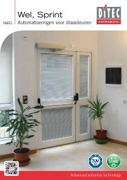
EN43211151292117131520196141618252423227810Ref. Description1 Box2 Gear motor K103 Winding shaft4 Transmission chain5 Counterweight belt drum6 Manual release lever7 Safety edge aluminium profile8 Safety edge rubber profile9 Safety edge connection box10 Safety edge connection cable11 Counterweight belt12 Modular counterweight13 Right-hand column coverRef. Description14 Left-hand column cover15 Right-hand column16 Left-hand column17 Curtain aluminium profiles18 Curtain reinforcing tube19 Control panel20 Photocell LAB421 Curtain lifting belt22 Curtain belt attachment23 Transparent section24 Polyester section25 Safety edge protective pocket2. TECHNICAL CHARACTERISTICSCONTROL PANEL TRIPHASE (49E)Power supply voltage ..........................400 V, 50/60 HzPower input ............................................................. 6 AAuxillary control power voltage.........................24VMotor rating....................................................0,75 KWControl board protection class............................. IP 55Operating temperature............................... - 5 + 50 °CCONTROL PANEL INVERTER (47E)Power supply voltage ......... 230 V monofase 50/60 HzPower input ........................................................... 10 AAuxillary control power voltage.........................24VMotor rating....................................................0,75 KWControl board protection class............................. IP 55Operating temperature............................... - 5 + 50 °C- 27 - 0DT829 2013-07-01
3. MECHANICAL INSTALLATIONSee the relevant drawings of the mechanical installation at page. 22 – 23 (central sheet to be removed).3.1 Initial checks (fig.1)• Check the size of the opening and that it corresponds to the measurements of the door supplied bearing in mind anytolerances needed if installed within the doorway. Check that obstacles do not prevent installation.• Make sure that the mounting surfaces are level and adjust them using suitably sized spacers if necessary.• Check the consistency of the opening structure: it must be securely anchored with brackets or plugs. If consistency is pooror uncertain, a suitable self-supporting metal structure must be provided.3.2 Fixing the uprights (fig.2)• Measure the overall dimensions of the crosspiece (LT) and mark the position of the uprights.• Remove the covers of the uprights and fix the bases according to the marks using M8 size plugs (fig.4).• Plumb the uprights and fix them at the indicated points (A) when using external brackets or (B) when fixing from insidethe column. M8 size plugs. Check the diagonals.Do not drill holes in the upright near the counterweight sliding area (C).3.3 Assembling the crosspiece• Remove the M8 bolts preassembled on the ends of the crosspiece.• Lift the crosspiece using appropriate lifting equipment.• Place the crosspiece on the uprights, reinsert the fixing bolts and tighten them (fig.3).• For doors with PL > 4000 we recommend fastening the crosspiece in the centre (to avoid unsightly bending of theframe).3.4 Placing the crosspiece in position• By referring to (fig.5A-5B-5C), place the belt transmission wheel according to the position of the curtain. The standardinstallation is as shown in (fig.5A).• If the belt transmission wheel does not remain in position “5A”, remove the wheel by loosening the M8 fixing bolt and putthe belt transmission wheel back into the required position. After fixing the wheel, check that it turns smoothly. Repeat thesame procedure for each support.3.5 Assembling the curtain• Insert the curtain in the uprights and lift it. Make sure that the belt rings are positioned correctly.• Using the M8 bolts supplied, fasten the curtain attachment sleeve to the crosspiece (fig.6).• Lower the curtain until it is completely unrolled. For <strong>Ditec</strong> <strong>Traffic</strong> C with a modular curtain: adjust the length of the curtainby rolling it onto the hook-up tubing if necessary.• Unwind the curtain lifting belts and leave at least two belt turns on the winding drum. (fig.9)• Insert the belts in the belt rings placed along the curtain. (fig.7)• Fix the end parts of the belts using the brackets on the 1st tube. (fig.7)• Fix the tubes using the plastic shells to prevent them sliding sideways (fig.8). The shells are already fixed on the 1st tube.3.6 Assembling the counterweights• Lift the counterweight using appropriate lifting equipment (forklift truck).• Unroll the belts and pass them around the transmission pulleys. Wind the belt around the upper pin and fix it using thespecial plate. Place the counterweight approximately 200 mm away from the stroke top end. (fig.9)• Finely adjust the balance using the 4 lower counterweight elements. (fig.9)3.7 Assembling the emergency release lever (optional)• The emergency release lever must be assembled at least 1.8 m off the ground (fig.10, 11).• Place the drive cable in the spaces and connect it to the gearmotor brake (fig.12, 13).• Check that the device is operating correctly; when the lever is operated, the curtain should be free to rise.• For <strong>Ditec</strong> <strong>Traffic</strong> <strong>CM</strong> with twin motors, the release devices are connected by way of the device shown in “figure 14”.3.8 Installing the photocells• Install the containers on the column (fig.15). For connections, follow the instructions in the photocell package.3.9 Installing the safety edge• Place the curtain at a height of approximately 1 m.• Insert the safety edge into the lower pocket of the curtain (fig.16).• Run the edge along the entire length of the curtain and place it in the exact centre of the curtain.0DT829 2013-07-01- 28 -
4. Electric connectionsEN4.1 Control panel• Insert the cables with pre-wired terminal boards in the housing, and connect them to the cards (fig.17). Fit the cables inthe conduit and connect the connectors on the motor (fig.18).4.2 Connecting the control panel / motor / security• Figure 19 shows the layout of the cables supplied, and their position in the door; each cable is identified by a special codeon an adhesive label.4.3 Safety photocells• Wire the device as per the diagram (fig.19).• Make the connections in the control panel, as shown in the diagrams171819A935G/E7825A - CA933A - 7823BA931C - 7824BA935LA451LA934E/L0 1Rx2Tx20 1798279820 10 1Tx1Rx1BlackBlueBlackBlueOrangeRedBlackBlueOrangeRedBlackBlueC T7825A7823A7824A7824A7823C/D7824C/D7824C/DA935E/F- 29 - 0DT829 2013-07-01
49E5.1 QUADRO 49E ELECTRONIC ELETTRONICO CONTROL 49E PANEL - Collegamenti- ConnectionsINPUTSCommand Function Description1 2 N.O Automatic closing Permanently closing the contact enables automatic closing.1 3 N.O Opening With DIP1=ON the closure of the contact activates an opening operation.Step-by-step With DIP1=OFF the closure of the contact activates an opening or closingoperation in the following sequence: open-stop-close-open.Note: if automatic closing is enabled, the stop is not permanent but at atime that is set by the TC.1 4 N.O Closing The closing manoeuvre starts when the contact is closed.1 6 N.C Reversal safetydevice41 8 N.C Reversal safetydeviceOpening the safety contact triggers a reversal of the movement (reopening)during a closing operation.Opening the safety contact triggers a reversal of the movement (reopening)during a closing operation.1 9 N.C Stop Opening the safety contact stops the current operation.1 9 N.O Non-pulse command Permanently opening the safety contact enables the operation by nonpulsecommand.In this state, the opening (1-3/1-20) and closing (1-4) controls function onlyif held in the pressed position, and the automation stops when the controlsare released.All safety switches, the step-by-step control and the automatic closingfunction are disabled.1 20 N.O Partial opening The closing of the contact activates a partial opening operation of theduration set with the RP trimmer.Once the automation stops, the partial opening control performs theopposite operation to the one performed before stoppage.0 11 N.C Closure limit switch The opening of the limit switch contact stops the closure operation.0 12 N.C Opening limit switch The opening of the limit switch contact stops the opening operation.0 17 Do not use Leave the input not connectedOperation by non-pulse commandOperation by pulse command17 14 12 11 0 0 0 1 1 2 3 4 6 8 9 20 4117 14 12 11 0 0 0 1 1 2 3 4 6 8 9 20 41OUTPUTSCard Output Value DescriptionEL07L1 +0 –0 1424 V= / 0,5 A24V= / 50 W(2 A)Accessories power supply.Power supply output for external accessories, includingautomation status lamp.Flashing light (LAMPH).Activated during opening and closing operations.- LK + 24 V= / 0,5 A Output activated during the door running.EL07PW1U W VM3 ~400 V~ / 4 AThree-phase motor.Note: if the direction of rotation of the motor is incorrect for thedesired direction of movement, swap the U - W phases.0DT829 2013-07-01- 30 -
49EENLSMLKCOMEL07L00000000000www.ditec.it41 1IN1FUSEF4EL07PW100000000000LSA<strong>CM</strong>LKJ71394LDVLDR20SOEOPRGU W VRP TCONON- LK +1 2 3 4 5 6OUT111 12 17 IN SA POWERNIO17 14 12 11 0 0 0 1 1 2 3 4 6 8 9 20 41A933A - 7823BRedWhiteBrownOrangeBlackBlueBlackBlueRedOrangeWhiteBrownL3 L2 L1BlackBlueOrangeRed7825A-CTConnection to be completedby installerA935LA935G / EBrownBlueBlackBlueOrangeRed0 1RX2TX20 1A451LA934E/L01SOFSOF01BlackBlueOrangeRedBlackBlueT0 1TX1TRX10 1BlueBlackTRedOrangeBlueBlack10161079827982A931C - 7824B17 14 12 11 0 0 0 1 1 2 3 4 6 8 9 20 41CPrewired standardconnectionBlackBlueOrangeRedBrownWhiteOrangeRedBlueBlack7825A-CA935CA935G / EBrownBlueBlackBlueOrangeRed0 1RX2TX20 1A451LA934E/L0184101BlackBlueOrangeRedBlackBlueC0 1TX1CRX10 1BlueBlackCRedOrangeBlueBlack10161079827982- 31 - 0DT829 2013-07-01
49ESIGNALS AND SETTINGTCTrimmer0 s 30 sDescriptionSetting automatic closing time. From 0 to 30 s.Note: after the activation of the stop command, once contact 1-9 has closed again, theautomatic closing is only activated after a total, partial or step-by-step opening command.RP Motor partial opening adjustment. From 0 to 30 s.0 s 30 s<strong>Ditec</strong> <strong>Traffic</strong>Dip-switchessettingON1 2 3 4 5 6Dip - switch Description OFF ONDIP 1 Control 1-3 function. Step-by-Step OpeningDIP 2Restore automatic closingtime.DIP 3 Preflashing set at 3 s.Do not use 100 %Disabled duringopeningEnabled for bothopening and closingDIP 4 Application type. Do not use Rapid doorDIP 5 Dynamic brake. Disabled Do not useDIP 6 Double speed Disabled Do not useJumpers Description OFF ONSOReversal safety switchfunction.With the automation blocked, if thecontacts 41-8 are open, it is possible toactivate the opening operation.EO Electric brake. Do not use Normal.LED On FlashingPOWER 24 V= power supply. /SAIN111217Indicates that at least one of the safetycontacts is open. ( 6 - 8 - 9 )Activated at every command andadjustment to the dip-switch and jumper.Indicates that the 0-11 limit switchcontact is open.Indicates that the 0-12 limit switchcontact is open.Indicates that the 0-17 limit switchcontact is open. (not used)With the automation blocked, ifthe contacts 41-8 are open, anyoperation is impossible.- Indicates the STOP operation activated by pushbutton panelPT4 (if present).- If the AUTOTEST device is installed, this indicates a safetytest failure (terminal 41).- On power on, the LED flashes to indicate the number ofoperations performed:each rapid flash = 10000 operationseach slow flash = 100000 operations////ONButtonStarts the opening operation.LEDThe green LED on indicates the presence of the 24 V=power supply.Starts the partial opening operation.Starts and stops the STOP operation.Starts the closing operation.the red LED on indicates that the STOP has been activated.the flashing red LED indicates that the safety devices have been activated.0DT829 2013-07-01- 32 -
49EENONEL07L00000000000www.ditec.itFUSEF4EL07PW100000000000COM1394LDVLDR20RP TCSOONEOONPRGU W V- LK +1 2 3 4 5 611 12 17 IN SA POWERNIO17 14 12 11 0 0 0 1 1 2 3 4 6 8 9 20 41L3 L2 L1F1F2F3FUSESID Value Dimension CircuitF1 - F2 - F3 8A - 500V 10.3 x 38 Three phase lineF4 3.15A - 230V 5 x 20 TransformerADJUSTment limit switch1. Activate the door by pressing the appropriate buttons, and check it movesin the correct direction and If necessary, reverse the movement directionby modifying the phase sequence, adjusting the line wires upstream ofthe main switch.2. Carry the curtain in the closed position.3. By means of a screwdriver, turn the “C” cam until the relative micro-switchis triggered.4. Carry out the same procedure for the opening limit switch: bring thecurtain to the open door position, and adjust cam “A”.5. Activate the automation to check the calibration and, if necessary, makea further adjustment.CAAC- 33 - 0DT829 2013-07-01
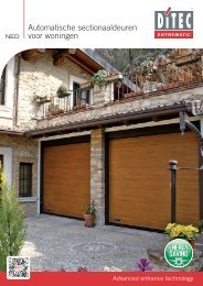
47E5.2 47E (INVERTER) ELECTRONIC CONTROL PANEL - ConnectionsINPUTSCommand Function Description1 2 N.O Automatic closing Permanently closing the contact enables automatic closing.1 3 N.O Opening The closure of the contact activates an opening operation.1 4 N.O Closing The closing manoeuvre starts when the contact is closed.41 40 N.C Reversal safetydevice1 8 N.C Reversal safetydeviceOpening the safety contact triggers a reversal of the movement (reopening)during a closing operation.Opening the safety contact triggers a reversal of the movement (reopening)during a closing operation.1 9 N.C Stop Opening the safety contact stops the current operation.1 9 N.O Non-pulsecommandPermanently opening the safety contact enables the operation by nonpulsecommandIn this state, the opening (1-3/1-20) and closing (1-4) controls function onlyif held in the pressed position, and the automation stops when the controlsare released.All safety switches, the step-by-step control and the automatic closingfunction are disabled.1 20 N.O Partial opening The closing of the contact activates a partial opening operation of theduration set with the RP trimmer.1 11 N.C Closure limit switch The opening of the limit switch contact stops the closure operation.1 12 N.C Limit switch The opening of the limit switch contact activates the slowdown in opening.slowdown1 13 N.C Opening limit switch The opening of the limit switch contact stops the opening operation.OUTPUTSOutput Value Description1 +0 -24 V= / 0,5 AAccessories power supply.Power supply output for external accessories, including automation statuslamp.LAMP230 V~ / 50 WFlashing light (LAMP).Activated during opening and closing operations.CNTCounter activationActivated in each closing motion-F +F 24 V= / 0,5 AElectric motor brake.The output is active for the duration of both the opening and closingoperation.U W VM3 ~230 V~ / 6 A Three-phase motor.0DT829 2013-07-01- 34 -
47ECNT+F -F U V WEN1716LSMLK1LSAB<strong>CM</strong>LKP 2.0IN 11 4 1 I N 1OUT1U24J215ONOFF 1 2 3 4131412T5T3T1T6T4T2GNDL NA933A - 7823BWhiteRedBlueBlackBrownOrangeP O W E RSOFA1J111 10 9 8 7 6 5 4 3 2 11 11 12 13DL41 40 20 9 8 4 3 2 1 1 0 LAMPF1 F2230 V 50/60 HzTConnection to be completedby installerBrownWhiteOrangeRedBlueBlackBlackBlueOrangeRed7825A-CA935LA935G / EBrownBlueBlackBlueOrangeRedA451LA934E/L01SOFSOF01BlackBlueOrangeRedBlackBlueT0 10 1RX2TX1TTX2RX10 10 1BlueBlackTRedOrangeBlueBlack10181079827982A931C - 7824BCPrewired standardconnection1 11 12 1341 40 20 9 8 4 3 2 1 1 0 LAMPBlackBlueOrangeRedBlackBlueRedOrangeWhiteBrown7825A-CA935LA935G / EBrownBlueBlackBlueOrangeRedA451LA934E/L01404101BlackBlueOrangeRedCBlackBlue0 10 1RX2TX1CTX2RX10 10 1BlueBlackCRedOrangeBlueBlack10181079827982- 35 - 0DT829 2013-07-01
47ESIGNALS AND SETTINGTrimmerDescriptionT1 Setting automatic closing time. From 0 to 30 s.0 s 30 sT2 Partial opening adjustment. From 0 to 10 s.0 s 10 sT30 MAXAdjust opening speed.T40 MAXAdjust closing speed.T50 MAXAdjust deceleration in opening.T60 MAXAdjust deceleration in closing. It define the exact closing point.Dip - switch Description OFF ONDIP 1Enable adjustment throughtrimmerDisabled.Enabled.DIP 2 Preflashing opening Disabled. Enabled.DIP 3 Future Use Do not use. Do not use.DIP 4 Future Use Do not use. Do not use.J2 Brake power supply Do not cut. 24 V BrakeLED Input ONDL1 (2) Automatic closingDL2 (3) OpeningDL3 (4) ClosingDL4 (9) StopDL5 (20) Partial openingDL6 (40) Safety edgeDL7Stop push buttonDL8 (8) Closing SafetyDL9 (13) Opening limit switchLED Input ONDL10 (12) Slowing down limit switchDL11 (11) Closing limit switchDL12Flashing lampDL13Run OKDL14FaultDL15AutotestDL16BrakeDL17Cycles counterButtonLEDONStarts the opening operation.The green LED on indicates the presence of the 24 V=power supply.Starts the partial opening operation.Starts and stops the STOP operation.Starts the closing operation.the red LED on indicates that the STOP has been activated.the flashing red LED indicates that the safety devices have been activated.0DT829 2013-07-01- 36 -
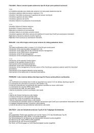
47ECNT+F -F U V WEN1716ON1GNDU24J215ONOFF 1 2 3 4131412T5T3T1T6T4T2LNJ111 10 9 8 7 6 5 4 3 2 1DLF1F21 11 12 1341 40 20 9 8 4 3 2 1 1 0 LAMP230 V 50/60 HzFUSESID Value Dimension CircuitF1 - F2 12A - 500V 10.3 x 38 monophase lineADJUSTment limit switchAdjusting the limit switch1. Set the deceleration ramps to zero. (T5 - T6)2. Calibrate the limit switch (C) on the gearmotor so the door stops approximately200-300mm from the closure point.3. Calibrate the opening limit switch (A) at the opening point.4. Calibrate slowdown limit switch (B) in such a way that it engages atapproximately ¾ of the opening stroke.5. Calibrate the opening speeds using trimmer (T3) and closure (T4).6. Calibrate the opening (T5) and closure (T6) trimmers of the decelerationramps in such a way as to cause stopping in the actual door open and doorclosed positions.CBAC300B¾ATROUBLESHOOTINGCOMMAND TROUBLE VERIFYEvery command, in everycurtain positionThe curtain and the motorsdon’t move• Control unit test was failed(led 13 green OFF, led 14 red ON)Opening CommandDuring the closingmovementThe motor run with slog orit doesn’t reach to the rightspeed (the brake wasn’tactivated)The motors doesn’t madedeceleration ramp• Check that jumper J2 has not been cut• Adjustment of the closing limit switch (C) at 300 mm fromthe floor• Adjustment of the deceleration ramp by means the trimmer T6NB for general diagnostics see also at page. 39- 37 - 0DT829 2013-07-01
6. CHECKING AND STARTING6.1 Check of the movement direction• Move the panel until it reaches half-way with respect to its stroke.• Open and close the door by pressing the relative push-buttons, and check the correct movement direction.• If required, reverse the movement direction by modifying the sequence of the phase and acting on the line cable beforethe main switch.6.2 Cable safety edge adjustments• Screw until micro switch trips, and then loosen a 1/2 turn. Block the contact (fig.20).200DT829 2013-07-01- 38 -
7. TROUBLESHOOTINGENDANGERWARNINGWhen working with electrical or electronic controls, make sure that the power source has been lockedout and tagged according to approved local electrical codes.The following instructions are intended only for qualified personnel, authorized to operate under theowners responsibility. Safety rules and local codes must be applied also when our instructions are notspecifying it in each single operation.For repair or replacement only <strong>Ditec</strong> Entrematic original spare parts must be used.COMMAND TROUBLE VERIFYAny command, in all thecurtain positionOpening command atclosed curtainThe curtain and motor donot moveThe motor turns in theopposite directionThe motor does not move• Mains power failure or fuses F1, F2, F3• The stop is activated (led “Stop” of the keyboard ON)• The motor is connected to wrong terminals and/or Dip-switchis in wrong position (see page 8)• The opening (A) and closing (C) limit switches are activated(led 11 and 12 ON)• Motor with thermal switch activated (led 11 and 12 ON)• One of the power devices is faulty (control unit, motor, motorcabling, etc.)• Reverse the two phases of the mains power supply• The opening command is not correctly connected or it is faulty(led IN does not switch ON).• Safety device activated (led “Stop” flashing on the keyboardand led SA fixed ON) with bridge SO closed.• The opening limit switch (A) is activated• Closure command always activated (led IN always ON).Closure command atopened curtainActivation of the stopduring a door cycleActivation of one safetydevice during closingThe motor does not moveThe motor does not stopThe motor stops withdelayThe motor movement isnot reversed• The closing command is not correctly connected or is faulty(led IN does not switch ON).• Safety device activated (led “Stop” flashing on the keyboardand led SA fixed ON).• The closing limit switch (C) is activated (led 11 fixed in ON).• Opening command always activated (led IN always ON).• Self-test of the safety device failed (led Stop on the keyboardOFF and led SA flashing)• The stop command is faulty or is not correctly connected (ledstop on the keyboard never in ON and led SA not flashing)• The motor brake worn-out or faulty• The safety device is faulty or is not correctly connected (ledStop on the keyboard OFF and led SA never flashing)Door open with automaticclosure activatedDuring operationThe motor movementstops (the door doesn’topen completely)The door does not closeautomatically after closingtime TCThe curtain doesn't stopat the limitswitchThe curtain doesn'tstop regularly at thelimitswitch• Input 17 closed to 0 (led 17 OFF)• The automatic closure enable signal has not been carried outproperly (connection 1-2)• Opening command always activated (led IN always ON).• Self-test of the safety device failed (led Stop on the keyboardOFF and led SA flashing)• The limit switch contact is short-circuited (led 11 or led 12always OFF)• A mechanical fault in the limit switch (led 11 or led 12 always OFF)• The motor brake worn-out or faulty or brake (led 11 or led 12always OFF)• Dip-switch 5 in OFF• Fuse F5 faultNB for inverter control unit 47E see also at page 37.- 39 - 0DT829 2013-07-01
8. MAINTENANCE TO BE CARRIED OUT EVERY 6 MONTHSRegular inspections should be made according to national regulations and product documentation by a <strong>Ditec</strong> Entrematictrained and qualified technician. The number of service occasions should be in accordance with national requirements andproduct documentation.Installation / Fitting• Tighten the fitting screws of the uprights with the crosspiece• Check the anchoring of the door to the door frameMotor• Check the fixing of the motor to the relevant support• Check the tensioning of the transmission chain• Check the limit switches functioning and the good alignment with the cams.• Check the brake disc wearing. If necessary replace the disc• Check the properly manual release lever brake functioning (when applicable)Main Shaft / Belt• Check the good bearing supports fixing• Lubricate the support of the bearings by suitable grease inlet• Check the wear and tear of the counterweight belts and the curtain. Replace the belts if necessarySafety Devices• Check the good safety bar functioning• Check the good conditions of the safety bar rubber profile• Check the adjusting and the eventual wearing of the steel cable of the electromechanical safety edge• Check the wearing of the mobile cable• Check the correct operation of the safety photocells8.1 Maintenance PlanThe table below shows the recommended interval - in months - when to replace parts during preventive maintenance.PartPart numberCycles / hour
USE INSTRUCTIONSENGENERAL SAFETY PRECAUTIONSThis user handbook is an integral and essential part of the product and must be delivered to the users. Keepthis document and pass it on to any future users.This automation is a “vertical-roll door”; it must be used for the specific purpose for which it was designed.Any other use is to be considered inappropriate and so dangerous. <strong>Ditec</strong> Entrematic declines all responsibilityfor damage caused by improper, incorrect or unreasonable use.USE PRECAUTIONS• Do not enter the door action area while the door is moving.• In the event of a fault or malfunctioning, turn off the main switch. The operations of maintenance, adjustmentand repair must be carried out by skilled and authorised staff.• Each automation has its own “Installation and Maintenance handbook”, reporting the periodical maintenanceplan. Please take care to check all the safety devices.BUTTONS• Full opening: the door opens completely. The stroke can be fixed via the end stop microswitch.• Partial opening: the door opens partially, to a point time-regulated by the RP trimmer.• STOP: the door stops immediately.DETACH AND DELIVER TO THE CUSTOMER• Closing: the door closes completely. The stroke can be fixed via the end stop microswitch.MANUAL RELEASE LEVER (for emergency reopening).Warning: before using the manual lever, turn the equipment off, putting the main switch on “0”.• When the lever is released, the brake is regularly working.• Pulling the lever, the brake is unclamped.To raise manually the panel, in case of power lacking or damage, act as follows:• pull the release lever (fig. 2), releasing the brake;• raise the panel on open door position;• leave the lever back (fig. 3), in order to run the brake again.Stop the opening of the panel before the safety edge hits the crosspiece.<strong>Ditec</strong> S.p.A.Via Mons. Banfi, 321042 Caronno P.lla (VA) - ItalyTel. +39 02 963911 - Fax +39 02 9650314www.ditecentrematic.comInstaller:- 41 - 0DT829 2013-07-01
8. MAINTENANCE TO BE CARRIED OUT EVERY 6 MONTHSRegular inspections should be made according to national regulations and product documentation by a <strong>Ditec</strong> Entrematictrained and qualified technician. The number of service occasions should be in accordance with national requirements andproduct documentation.Installation / Fitting• Tighten the fitting screws of the uprights with the crosspiece• Check the anchoring of the door to the door frameMotor• Check the fixing of the motor to the relevant support• Check the tensioning of the transmission chain• Check the limit switches functioning and the good alignment with the cams.• Check the brake disc wearing. If necessary replace the disc• Check the properly manual release lever brake functioning (when applicable)Main Shaft / Belt• Check the good bearing supports fixing• Lubricate the support of the bearings by suitable grease inlet• Check the wear and tear of the counterweight belts and the curtain. Replace the belts if necessarySafety Devices• Check the good safety bar functioning• Check the good conditions of the safety bar rubber profile• Check the adjusting and the eventual wearing of the steel cable of the electromechanical safety edge• Check the wearing of the mobile cable• Check the correct operation of the safety photocells8.1 Maintenance PlanThe table below shows the recommended interval - in months - when to replace parts during preventive maintenance.PartPart numberCycles / hour
APPLICATIONSENUse: 5 (minimum 5 years of working life with 600 cycles a day)Applications: HEAVY DUTY (for industrial and commercial access with heavy duty use).• Service class, running times, and the number of consecutive cycles are to be taken as merely indicative having beenstatistically determined under average operating conditions, and cannot therefore be applied to each individual case.Reference is to the period when the product functions without the need for any extraordinary maintenance.• Independent variables such as friction, balancing and environmental factors may substantially alter the lifespan orperformance characteristics of the automatic access or parts thereof (including the automatic systems). It is the responsibilityof the installer to adopt suitable safety measures for each single installation.DECLARATION OF CONFORMITYWe:Entrematic Group ABLodjursgatan 10SE-261 44 LandskronaSwedendeclare under our sole responsibility that the type of equipment with name / description:TRAFFIC C - TRAFFIC <strong>CM</strong>Folding high speed door with counterweightWith performance levels as declared in the accompanying Declaration of Performance and the product label, and electricaldrive unit as identified in the log book provided with it, is in compliance with the following directives:2006/42/EC2004/108/E<strong>CM</strong>achinery Directive (MD)ElectroMagnetic Compatibility Directive (EMCD)Harmonized European standards which have been applied:EN 13241-1 EN 61000-6-2 EN 61000-6-3 EN 60335-1 EN 60204-1Other standards or technical specifications, which have been applied:EN 60335-2-103EC type examination or certificate issued by a notified or competent body (for full address, please contact Entrematic GroupAB) concerning the equipment:CSI Spa Reg. - N° 0497Certificate Nr.: DE/051/05The manufacturing process ensures the compliance of the equipment with the technical file. The manufacturing process isregularly accessed by 3rd party.Compilation of technical file:Marco Pietro ZiniEntrematic Group ABLodjursgatan 10SE-261 44 LandskronaSwedenE-mail: marco.zini@entrematic.comPlace Date Signature PositionLandskrona 2013-07-01 Marco Pietro Zini President Entrance Automation- 43 - 0DT829 2013-07-01
ISO 9001Cert. n°0957Entrematic Italy S.p.A.Via Mons. Banfi, 3 ▪ 21042 Caronno P.lla (VA) ▪ ItalyTel +39 02 963911 ▪ Fax: +39 02 9650314www.ditecentrematic.com2013-07-01ODT829È presente in: Belgio, Francia, Germania, Portogallo, Spagna, Svezia, Svizzera,Turchia, America Latina, USA, Canada e Cina.Per indirizzi e contatti visitare il nostro sito web www.ditecentrematic.com