Drehfutter - Rerom
Drehfutter - Rerom
Drehfutter - Rerom

Sie wollen auch ein ePaper? Erhöhen Sie die Reichweite Ihrer Titel.
YUMPU macht aus Druck-PDFs automatisch weboptimierte ePaper, die Google liebt.
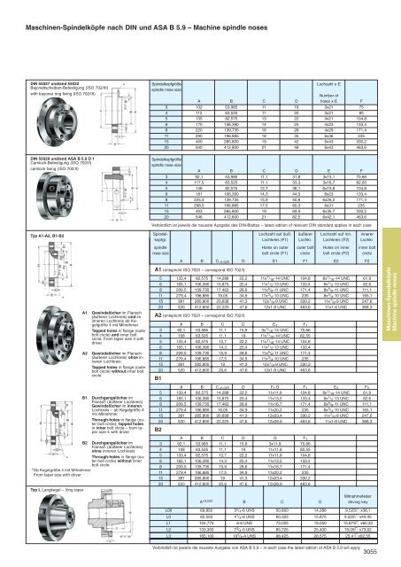
Maschinen-Spindelköpfe nach DIN und ASA B 5.9 – Machine spindle nosesDIN 55027 und/and 55022Bajonettscheiben-Befestigung (ISO 702/III)with bayonet ring fixing (ISO 702/III)*SpindelkopfgrößeLochzahl x Espindle nose sizeNumber ofA B C D holes x E F3 102 53,985 11 16 3x21 754 112 63,525 11 20 3x21 855 135 82,575 13 22 4x21 104,86 170 106,390 14 25 4x23 133,48 220 139,735 16 28 4x29 171,411 290 196,885 18 35 6x36 23515 400 285,800 19 42 6x43 330,220 540 412,800 21 48 6x43 463,6DIN 55029 und/and ASA B 5.9 D 1Camlock-Befestigung (ISO 702/II)camlock fixing (ISO 702/II)Typ A1-A2, B1-B2Spindelkopfgrößespindle nose sizeA B C D E F3 92,1 53,985 11,1 31,8 3x15,1 70,664 117,5 63,525 11,1 33,3 3x16,7 82,555 146 82,575 12,7 38,1 6x19,8 104,86 181 106,390 14,3 44,5 6x23 133,48 225,4 139,735 15,9 50,8 6x26,2 171,411 298,5 196,885 17,5 60,3 6x31 23515 403 285,800 19 69,9 6x35,7 330,220 546 412,800 21 82,5 6x42,1 463,6Verbindlich ist jeweils die neueste Ausgabe des DIN-Blattes – latest edition of relevant DIN standard applies in each caseSpindel- Lochzahl auf äuß. äußerer Lochzahl auf inn. innererkopfgr. Lochkreis (F1) Lochkr. Lochkreis (F2) Lochkr.spindle Holes on outer outer bolt Holes on inner inner boltnose size bolt circle (F1) circle bolt circle (F2) circleA B C –0,025 D E1 F1 E2 F2*A1A2Gewindelöcher im Flansch(äußerer Lochkreis) und iminneren Lochkreis ab Kegelgröße4 mit MitnehmerTapped holes in flange (outerbolt circle) and inner boltcircle. From taper size 4 withdriverGewindelöcher im Flansch(äußerer Lochkreis) ohne innerenLochkreisTapped holes in flange (outerbolt circle) without inner boltcircleA1 (entspricht ISO 702/I – correspond ISO 702/I)5 133,4 82,575 14,288 22,2 11x 7 / 16 -14 UNC 104,8 8x 7 / 16 -14 UNC 61,96 165,1 106,390 15,875 25,4 11x 1 / 2 -13 UNC 133,4 8x 1 / 2 -13 UNC 82,68 209,5 139,735 17,462 28,6 11x 5 / 8 -11 UNC 171,4 8x 5 / 8 -11 UNC 111,111 279,4 196,885 19,05 34,9 11x 3 / 4 -10 UNC 235 8x 3 / 4 -10 UNC 165,115 381 285,800 20,638 41,3 12x 7 / 8 -9 UNC 330,2 11x 7 / 8 -9 UNC 247,620 520 412,800 22,225 47,6 12x1-8 UNC 463,6 11x1-8 UNC 368,3A2 (entspricht ISO 702/I – correspond ISO 702/I)A B C D E 1 F 13 92,1 53,985 11,1 15,9 3x 7 / 16 -14 UNC 70,664 108 63,525 11,1 19 11x 7 / 16 -14 UNC 82,555 133,4 82,575 12,7 22,2 11x 7 / 16 -14 UNC 104,86 165,1 106,390 14,3 25,4 11x 1 / 2 -13 UNC 133,48 209,5 139,735 15,9 28,6 11x 5 / 8 -11 UNC 171,411 279,4 196,885 17,5 34,9 11x 3 / 4 -10 UNC 23515 381 285,800 19 41,3 12x 7 / 8 -9 UNC 330,220 520 412,800 20,6 47,6 12x1-8 UNC 463,6B1Maschinen-SpindelköpfeMachine spindle nosesB1Durchgangslöcher imFlansch (äußerer Lochkreis)Gewindelöcher im innerenLochkreis – ab Kegelgröße 4mit MitnehmerThrough-holes in flange (outerbolt circle), tapped holesin inner bolt circle – from tapersize 4 with driverB2 Durchgangslöcher imFlansch (äußerer Lochkreis)ohne inneren LochkreisThrough-holes in flange (outerbolt circle) without inner*bolt circle* Ab Kegelgröße 4 mit MitnehmerFrom taper size with driverTyp L Langkegel – long taperA B C –0,025 D F 1 G F 1 E 2 F 25 133,4 82,575 14,288 22,2 11x11,9 104,8 8x 7 / 16 -14 UNC 61,96 165,1 106,390 15,875 25,4 11x13,5 133,4 8x 1 / 2 -13 UNC 82,68 209,5 139,735 17,462 28,6 11x16,7 171,4 8x 5 / 8 -11 UNC 111,111 279,4 196,885 19,05 34,9 11x20,2 235 8x 3 / 4 -10 UNC 165,115 381 285,800 20,638 41,3 12x23,4 330,2 11x 7 / 8 -9 UNC 247,620 520 412,800 22,225 47,6 12x26,6 463,6 11x1-8 UNC 368,3B2A B C D G F 13 92,1 53,985 11,1 15,9 3x11,9 70,664 108 63,525 11,1 19 11x11,9 82,555 133,4 82,575 12,7 22,2 11x11,9 104,86 165,1 106,390 14,3 25,4 11x13,5 133,48 209,5 139,735 15,9 28,6 11x16,7 171,411 279,4 196,885 17,5 34,9 11x20,2 23515 381 285,800 19 41,3 12x23,4 330,220 520 412,800 20,6 47,6 12x26,6 463,6MitnahmefederA +0,051 B C D driving keyL00L0L1L2L369,85082,550104,775133,350165,1003 3 / 4 -6 UNS4 1 / 2 -6 UNS6-6 UNS7 3 / 4 -5 UNS10 3 / 8 -4 UNS50,80060,32573,02585,72598,42514,28815,87519,05025,40028,575 9,525 / /x38,19,525 / /x44,4515,875 / /x60,3219,05 / /x73,0225,4 / /x82,55Verbindlich ist jeweils die neueste Ausgabe von ASA B 5.9 – in each case the latest edition of ASA B 5.9 will apply3055