Bedienungsanleitung Telic STD 32 User Manual - Elfa
Bedienungsanleitung Telic STD 32 User Manual - Elfa
Bedienungsanleitung Telic STD 32 User Manual - Elfa

Erfolgreiche ePaper selbst erstellen
Machen Sie aus Ihren PDF Publikationen ein blätterbares Flipbook mit unserer einzigartigen Google optimierten e-Paper Software.
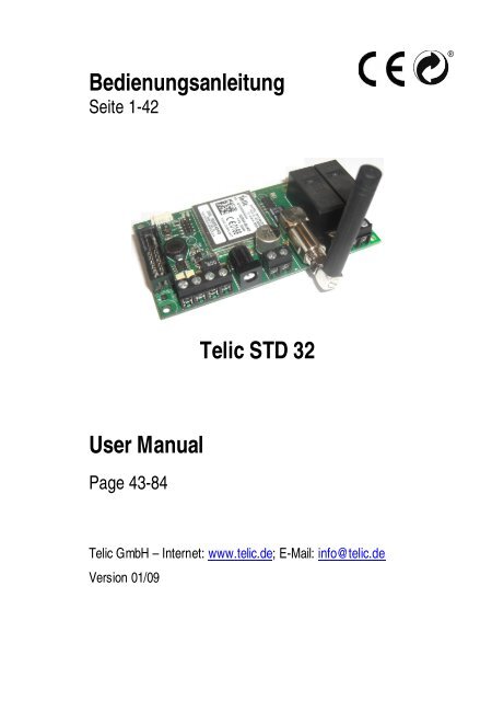
<strong>Bedienungsanleitung</strong><br />
Seite 1-42<br />
<strong>User</strong> <strong>Manual</strong><br />
Page 43-84<br />
<strong>Telic</strong> <strong>STD</strong> <strong>32</strong><br />
<strong>Telic</strong> GmbH – Internet: www.telic.de; E-Mail: info@telic.de<br />
Version 01/09
1 Einleitung ......................................4<br />
1.1 Achtung, bitte lesen .......................6<br />
2 Erklärung technischer Grundlagen..9<br />
2.1 GSM-Netz im Allgemeinen .............9<br />
2.2 GPRS............................................9<br />
2.3 Quadband Frequenzen ................10<br />
2.4 Internet im Allgemeinen................10<br />
2.5 E-Mail via SMTP..........................11<br />
2.6 Web Server .................................12<br />
2.7 Fixed IP.......................................12<br />
3 Betriebsbedingungen...................13<br />
4 Bestimmungsgem. Verwendung...14<br />
5 Einführung...................................15<br />
6 Schnellstart-Anleitung ..................17<br />
6.1 Allgemeine Vorbereitungen ..........17<br />
6.2 Vorbereitungen an der Hardware..19<br />
6.3 Konfiguration per Anruf ................19<br />
6.4 Schnelltest der Konfiguration........21<br />
7 Übersicht der SMS Kommandos...21<br />
7.1 SMS Kommando schicken ...........22<br />
7.2 Erklärung der Kommandos...........24<br />
7.3 Beispiele SMS Kommandos .........27<br />
2
8 E-Mail Funktionen via GPRS ....... 28<br />
8.1 Einrichten der E-Mail Funktion ..... 29<br />
9 Internet-Zugriff auf das <strong>STD</strong><strong>32</strong>..... 33<br />
10 Anbindung der Kamera................ 34<br />
11 Fehlerbehandlung ....................... 35<br />
12 Anschlussbeispiele...................... 36<br />
13 Zubehör ...................................... 40<br />
14 Technische Daten und Hotline ..... 42<br />
3
1 Einleitung<br />
Vielen Dank, dass Sie sich für den Kauf eines <strong>STD</strong><strong>32</strong><br />
Telemetriemoduls aus dem Hause <strong>Telic</strong> entschieden haben!<br />
Das <strong>STD</strong><strong>32</strong> bietet nahezu jedem Nutzer die Möglichkeit, aus<br />
der Ferne Verbraucher ein- und auszuschalten und Alarme<br />
übermittelt zu bekommen. Dabei kann die Übertragung von<br />
Schalt- und Alarmmeldungen per SMS über jedes SMS-fähige<br />
Handy oder über einen Sprachanruf erfolgen.<br />
Mit der neuen Generation des <strong>STD</strong><strong>32</strong> ist es Ihnen ab sofort<br />
zusätzlich möglich, E-Mails als Alarmmeldung zu versenden.<br />
Mit der als Zubehör verfügbaren Digitalkamera können im<br />
Alarmfall sogar Fotos aufgenommen und ebenfalls per E-Mail<br />
verschickt werden.<br />
Der auf dem <strong>STD</strong><strong>32</strong> implementierte Webserver erlaubt darüber<br />
hinaus den direkten Internet-Zugriff per Standard-Webbrowser<br />
(wie z.B. Internet Explorer oder Firefox) vom PC oder von<br />
Ihrem internetfähigen Handy aus. Somit lassen sich sehr<br />
einfach Verbraucher über das Internet von überall aus schalten<br />
und Konfigurationen des <strong>STD</strong><strong>32</strong> verändern.<br />
Wir wünschen Ihnen viel Erfolg und viel Freude bei der<br />
Nutzung Ihres neuen <strong>STD</strong><strong>32</strong>!<br />
Zu dieser Anleitung:<br />
Diese Anleitung beschreibt die Grundfunktionen des<br />
<strong>STD</strong><strong>32</strong>. Eine ausführliche Fassung dieser Anleitung finden<br />
Sie auf der Homepage der <strong>Telic</strong> GmbH unter www.telic.de.<br />
Hier werden auch Funktionserweiterungen und neue<br />
Anwendungen beschrieben, die Ihnen weitere<br />
Einsatzmöglichkeiten mit dem <strong>STD</strong><strong>32</strong> ermöglichen.<br />
4
Die vorliegende Dokumentation soll Ihnen helfen, die<br />
vielfältigen Funktionen des Geräts optimal zu nutzen. Daher<br />
lesen Sie sich diese Anleitung bitte sorgfältig durch.<br />
Wenn Sie in Eile sind und sich mit den Details des Produkts<br />
später vertraut machen möchten, dann lesen Sie bitte zuerst<br />
Kapitel 6 „Schnellstart Anleitung“.<br />
Dort finden Sie alle wichtigen Informationen, um das Gerät<br />
schnell in Betrieb nehmen zu können.<br />
Alle Angaben in dieser Dokumentation sind nach sorgfältiger<br />
Prüfung zusammengestellt worden, gelten jedoch nicht als<br />
Zusicherung von Produkteigenschaften.<br />
Die Weitergabe und Vervielfältigung der zu diesem Produkt<br />
gehörenden Dokumentation und Software und die Verwendung<br />
ihres Inhalts sind nur mit schriftlicher Erlaubnis der <strong>Telic</strong> GmbH<br />
gestattet.<br />
<strong>Telic</strong> behält sich vor, die genannten Daten ohne Ankündigung<br />
zu ändern und übernimmt keine Gewähr für technische<br />
Ungenauigkeiten und/oder Auslassungen.<br />
Sollten Sie trotz sorgfältiger Bearbeitung dieser Anleitung<br />
dennoch einen Fehler finden oder einfach nur Kritik oder<br />
Anregung zu dieser Dokumentation äußern wollen, dann<br />
senden Sie bitte eine E-Mail direkt an<br />
E-Mail: support@<strong>Telic</strong>.de<br />
Oberhaching, den 23. Januar 2009<br />
© 2009 <strong>Telic</strong> GmbH, Oberhaching<br />
5
1.1 Achtung, bitte lesen<br />
Diese <strong>Bedienungsanleitung</strong> enthält wichtige Hinweise zur<br />
Inbetriebnahme und Handhabung des <strong>STD</strong><strong>32</strong>, bitte lesen Sie<br />
diese aufmerksam, bevor Sie das <strong>STD</strong><strong>32</strong> in Betrieb nehmen!<br />
Bei Schäden, die durch die Nichtbeachtung der<br />
<strong>Bedienungsanleitung</strong> entstehen, erlischt der Garantieanspruch!<br />
Für Folgeschäden, die daraus resultieren, übernimmt die Firma<br />
<strong>Telic</strong> keine Haftung.<br />
Bei Sach- oder Personenschäden, die durch unsachgemäße<br />
Handhabung oder Nichtbeachtung der Sicherheitshinweise<br />
verursacht werden, übernimmt die Firma <strong>Telic</strong> keine Haftung.<br />
In solchen Fällen erlischt jeder Garantieanspruch.<br />
Derjenige, der eine Baugruppe durch Erweiterung bzw.<br />
Gehäuseeinbau betriebsbereit macht, gilt nach DIN VDE 0869<br />
als Hersteller und ist verpflichtet, bei Weitergabe des Gerätes<br />
alle Begleitpapiere mitzuliefern und auch seinen Namen und<br />
Anschrift anzugeben. Geräte, die aus Baugruppen selbst<br />
zusammengestellt werden sind sicherheitstechnisch wie ein<br />
industrielles Produkt zu betrachten.<br />
Das <strong>STD</strong><strong>32</strong> ist mit hoch integrierten Bausteinen bestückt.<br />
Diese elektronischen Bauteile sind technologisch bedingt sehr<br />
empfindlich gegen Entladungen statischer Elektrizität.<br />
6<br />
Bitte berühren Sie das <strong>STD</strong><strong>32</strong> daher nur an<br />
den Seitenrändern und vermeiden Sie die<br />
Berührung der Pins von Bauelementen auf<br />
der Platine.
Während des Betriebs des <strong>STD</strong><strong>32</strong> können automatisch GSM-<br />
Kurznachrichten (SMS) verschickt bzw. GPRS Verbindungen<br />
aufgebaut werden, wodurch Ihnen Kosten von Ihrem<br />
Mobilfunknetzbetreiber in Rechnung gestellt werden, ähnlich<br />
der Nutzung Ihres Handys.<br />
Sicherheitshinweise<br />
Beim Umgang mit Produkten, die mit elektrischer<br />
Spannung in Berührung kommen, müssen die<br />
gültigen VDE-Vorschriften beachtet werden,<br />
insbesondere VDE 0100, VDE 0550/0551, VDE<br />
0700, VDE 0711 und VDE 0860.<br />
Alle Verdrahtungsarbeiten dürfen nur im spannungslosen<br />
Zustand ausgeführt werden.<br />
� Spannungsführende Kabel oder Leitungen, mit denen das<br />
Gerät, das Bauteil oder die Baugruppe verbunden ist,<br />
müssen stets auf Isolationsfehler oder Bruchstellen<br />
untersucht werden. Bei Feststellen eines Fehlers in der<br />
Zuleitung muss das Gerät unverzüglich aus dem Betrieb<br />
genommen werden, bis die defekte Leitung ausgewechselt<br />
worden ist.<br />
� Es ist vor der Inbetriebnahme eines Gerätes generell zu<br />
prüfen, ob dieses Gerät oder Baugruppe grundsätzlich für<br />
den Anwendungsfall, für den es verwendet werden soll,<br />
geeignet ist! Im Zweifelsfall sind unbedingt Rückfragen bei<br />
Fachleuten, Sachverständigen oder den Herstellern der<br />
verwendeten Baugruppen notwendig!<br />
� Bitte beachten Sie, dass Bedien- und Anschlussfehler<br />
außerhalb unseres Einflussbereiches liegen.<br />
7
Verständlicherweise können wir für Schäden, die daraus<br />
entstehen keinerlei Haftung übernehmen.<br />
� Vor dem Öffnen eines Gerätes stets den Netzstecker<br />
ziehen oder sicherstellen, dass das Gerät stromlos ist.<br />
� Bauteile, Baugruppen oder Geräte dürfen nur in Betrieb<br />
genommen werden, wenn sie vorher berührungssicher in<br />
ein Gehäuse eingebaut wurden. Während des Einbaus<br />
müssen sie stromlos sein.<br />
� Werkzeuge dürfen an Geräten, Bauteilen oder Baugruppen<br />
nur benutzt werden, wenn sichergestellt ist, dass die Geräte<br />
von der Versorgungsspannung getrennt sind und<br />
elektrische Ladungen, die in den im Gerät befindlichen<br />
Bauteilen gespeichert sind, vorher entladen wurden.<br />
� Bei Einsatz von Bauelementen oder Baugruppen muss<br />
stets auf die strikte Einhaltung, der in der zugehörigen<br />
Beschreibung genannten Kenndaten für elektrische Größen<br />
hingewiesen werden.<br />
� Wenn aus einer vorliegenden Beschreibung für den<br />
nichtgewerblichen Endverbraucher nicht eindeutig<br />
hervorgeht, welche elektrischen Kennwerte für ein Bauteil<br />
oder eine Baugruppe gelten, wie eine externe Beschaltung<br />
durchzuführen ist oder welche externen Bauteile oder<br />
Zusatzgeräte angeschlossen werden dürfen und welche<br />
Anschlusswerte diese externen Komponenten haben<br />
dürfen, so muss stets ein Fachmann um Auskunft ersucht<br />
werden.<br />
� Geräte, die an einer Spannung > 35 Volt betrieben werden,<br />
dürfen nur vom Fachmann angeschlossen werden.<br />
� Die Inbetriebnahme darf grundsätzlich nur erfolgen, wenn<br />
die Schaltung absolut berührungssicher in ein Gehäuse<br />
eingebaut ist.<br />
8
� Sind Messungen am geöffneten Gehäuse unumgänglich, so<br />
muss aus Sicherheitsgründen ein Trenntrafo<br />
zwischengeschaltet werden, oder, wie bereits erwähnt, die<br />
Spannung über ein geeignetes Netzteil, (das den<br />
Sicherheitsbestimmungen entspricht) zugeführt werden.<br />
2 Erklärung technischer Grundlagen<br />
2.1 GSM-Netz im Allgemeinen<br />
Das GSM Netz (Global System for Mobile Communications) ist<br />
ein Standard für volldigitale Mobilfunknetze. GSM wurde mit<br />
dem Ziel geschaffen, ein mobiles Telefonsystem anzubieten,<br />
das Teilnehmern eine europaweite Mobilität erlaubt und mit<br />
ISDN oder herkömmlichen analogen Telefonnetzen kompatible<br />
Sprachdienste anbietet.<br />
GSM wurde ursprünglich für Telefongespräche, für die<br />
Versendung von SMS (Kurznachrichten) und für die<br />
Datenübertragung mit konstanter Datenrate konzipiert. Mit dem<br />
Erfolg des Internets begann jedoch ein Umdenken, die so<br />
genannte „Evolution von GSM“, bei der das GSM Netz komplett<br />
abwärtskompatibel mit Möglichkeiten zur paketorientierten<br />
Datenübertragung (z.B via GPRS) erweitert wurde.<br />
2.2 GPRS<br />
Bei GPRS (General Packet Radio Service) handelt es sich um<br />
einen paketorientierten Übertragungsdienst, der im Bereich des<br />
Mobilfunks eingesetzt und von so gut wie allen<br />
Mobilfunknetzen unterstützt wird.<br />
Hierbei besteht nur virtuell eine dauerhafte Verbindung zur<br />
Gegenstelle. Erst wenn wirklich Daten übertragen werden, wird<br />
der Funkraum besetzt, ansonsten ist er für andere Benutzer<br />
9
frei. Somit wird kein Funkkanal dauerhaft (wie bei GSM<br />
Sprachverbindungen) für einen Benutzer reserviert. Deshalb<br />
sind die GPRS-Abrechnungen hauptsächlich von den<br />
übertragenen Datenmengen abhängig und weniger von der<br />
Verbindungsdauer.<br />
Ist das Gerät im GPRS-Netz eingebucht bekommt es<br />
automatisch eine IP-Adresse zugewiesen und kann damit<br />
einen Datenaustausch mit jedem im Internet erreichbaren<br />
Server durchführen.<br />
Zur Verwendung der GPRS - Schnittstelle muss die eingelegte<br />
SIM - Karte für GPRS freigeschaltet sein. Diese Funktion<br />
können Sie beim Provider Ihres Mobilfunknetzes bestellen.<br />
2.3 Quadband Frequenzen<br />
Wenn ein Gerät „Quadband fähig“ ist, bedeutet dies, dass es<br />
die vier Haupt-GSM –Frequenzen nutzt und somit kompatibel<br />
zu den meisten Netzen weltweit ist.<br />
Diese vier Frequenzbereiche betragen 850 MHz und 1900 MHz<br />
(auf dem amerikanischen Kontinent genutzt) und 900 MHz und<br />
1800 MHz, die in den meisten restlichen Ländern der Welt<br />
verwendet werden (Europa und Asien).<br />
Im Gegensatz zu einem Triband-Telefon, das lediglich die<br />
Netze 900/1800 und 1900 beziehungsweise 850/1800 und<br />
1900 unterstützt, kann ein Quadband Gerät praktisch in jedem<br />
GSM-Netz der Welt verwendet werden.<br />
2.4 Internet im Allgemeinen<br />
Das Internet ist heute ein weltweites Netzwerk bestehend aus<br />
vielen Rechnernetzwerken, durch das weltweit Daten<br />
10
ausgetauscht werden. Es ermöglicht die Nutzung der<br />
Internetdienste wie WWW, E-Mail, FTP oder VoIP (Telefonie).<br />
Im Prinzip kann dabei jeder Rechner weltweit mit jedem<br />
anderen Rechner verbunden werden. Der Datenaustausch<br />
zwischen den einzelnen Internet-Rechnern erfolgt über das<br />
technisch normierte Internetprotokoll (IP).<br />
2.5 E-Mail via SMTP<br />
Das SMTP (Simple Mail Transfer Protocol) ist ein Verfahren<br />
zum Senden von E-Mails im Internet. Die Abwicklung wird für<br />
den Anwender unsichtbar durch ein Mailprogramm<br />
vorgenommen, das in diesem Fall auf dem <strong>STD</strong><strong>32</strong> abläuft und<br />
SMTP unterstützt. Dieses Programm verbindet sich mit einem<br />
SMTP-Server, der die Mail über ggf. weitere SMTP-Server, zur<br />
angegebenen E-Mail Adresse transportiert.<br />
Um diesen Dienst nutzen zu können, muss ein E-Mail Konto<br />
bei einem Mail-Provider (wie z.B. AOL oder Yahoo) vorhanden<br />
sein, und es müssen folgende Einstellungen gemacht werden,<br />
die vom Mail-Provider (wie z.B. AOL oder Yahoo) abhängig<br />
sind:<br />
� Name des SMTP Servers (z.B. smtp.mailprovider.com oder<br />
192.168.234.12)<br />
� Benutzername zum Anmelden am SMTP Server<br />
� Passwort zum Anmelden am SMTP Server<br />
Die von <strong>Telic</strong> getesteten E-Mail Provider finden Sie auf unserer<br />
Webseite www.telic.de.<br />
11
Welche Einstellungen am <strong>STD</strong><strong>32</strong> vorgenommen werden<br />
müssen, um diesen Dienst zu nutzen erfahren Sie unter<br />
Abschnitt 8.<br />
2.6 Web Server<br />
Ein Webserver ist ein Programm, das auf einem Gerät läuft,<br />
dem so genannten Server, um Daten und Dokumente an<br />
Clients (z.B. Standard-Webbrowser wie der Internet Explorer<br />
oder Firefox) zu übertragen. Webserver werden überwiegend<br />
als WWW-Dienst im Internet eingesetzt. Die Daten und<br />
Dokumente können von jedem Computer der mit dem Internet<br />
verbunden ist weltweit abgerufen und angezeigt werden.<br />
Ein solcher Webserver ist auch auf dem <strong>STD</strong><strong>32</strong> implementiert.<br />
Zur Nutzung dieser Funktion müssen Sie einige<br />
Besonderheiten beachten. Näheres hierzu finden Sie unter<br />
Kapitel „9. Internet-Zugriff auf das <strong>STD</strong><strong>32</strong>“.<br />
2.7 Fixed IP<br />
IP-Adressen werden in Computernetzen, die auf dem<br />
Internetprotokoll (IP) basieren, verwendet, um Daten von ihrem<br />
Absender zum vorgesehenen Empfänger transportieren zu<br />
können. Ein Beispiel derartiger Computernetze ist das Internet.<br />
Um einen Webserver ansprechen zu können muss dessen IP-<br />
Adresse bekannt sein, damit z.B. der Webbrowser Daten von<br />
diesem laden und anzeigen kann. Deshalb werden für Server<br />
meist nur feste IP-Adressen verwendet (Fixed IP).<br />
Die bekannteste Notation der heute geläufigen IP-Adressen<br />
besteht aus vier Zahlen, die jeweils zwischen 0 und 255 liegen<br />
12
und mit einem Punkt getrennt werden, beispielsweise<br />
127.0.0.1.<br />
Um den Webserver auf dem <strong>STD</strong><strong>32</strong> nutzen zu können muss<br />
der Provider Ihres Mobilfunknetzes dem Gerät eine feste IP-<br />
Adresse zuweisen und einen Verbindungsaufbau aus dem<br />
Internet zulassen. Diese Funktion ist meist nur auf Anfrage<br />
oder bei speziellen GSM-Netzwerkanbietern erhältlich.<br />
3 Betriebsbedingungen<br />
� Betreiben Sie das <strong>STD</strong><strong>32</strong> nur mit einer Betriebsspannung<br />
zwischen 5-<strong>32</strong>V DC (Gleichstrom) und beachten Sie die<br />
Polarität! (siehe Abb.1). Es ist ein stabilisiertes Netzteil mit<br />
mindestens 1A Ausgangsstrom zu verwenden (wir raten<br />
Ihnen dringend das <strong>Telic</strong> Original-Netzteil zu verwenden).<br />
Verwenden Sie ein Netzgerät als Spannungsquelle, so<br />
muss dies unbedingt den VDE-Vorschriften entsprechen!<br />
� Bei Geräten mit einer Betriebsspannung >35V, die an<br />
einem der Relais angeschlossen sind, darf die Endmontage<br />
nur vom Fachmann unter Einhaltung der VDE-<br />
Bestimmungen vorgenommen werden!<br />
� An der Baugruppe angeschlossene Verbraucher dürfen<br />
eine Anschlussleistung von max. 1000W pro Relais nicht<br />
überschreiten.<br />
� Die maximale Schaltspannung beträgt 250V AC<br />
(Wechselstrom)<br />
� Der durch die Leiterbahnbreite bedingte maximale<br />
Schaltstrom (pro Relais) beträgt 6A.<br />
� Bei der Installation des Gerätes ist auf ausreichenden<br />
Kabelquerschnitt der Anschlussleitungen zu achten.<br />
13
� Die zulässige Umgebungstemperatur darf während des<br />
Betriebs -20°C nicht unter- und 55°C nicht überschreiten.<br />
� Das Gerät ist zum Betrieb in trockenen und sauberen<br />
Räumen bestimmt.<br />
� Schützen Sie das Gerät vor Feuchtigkeit, Spritzwasser und<br />
Hitzeeinwirkung.<br />
� Bei Bildung von Kondenswasser muss eine<br />
Akklimatisierungszeit von bis zu 2 Stunden abgewartet<br />
werden.<br />
� Betreiben Sie das Gerät nicht in einer Umgebung in welcher<br />
brennbare Gase, Dämpfe oder Staub vorhanden sind oder<br />
vorhanden sein könnten.<br />
� Setzen Sie das Gerät keinen starken Vibrationen aus.<br />
� Eine Reparatur des Geräts darf nur vom Fachmann<br />
vorgenommen werden.<br />
� Falls das Gerät repariert werden muss, dürfen<br />
ausschließlich Original-Ersatzteile verwendet werden. Die<br />
Verwendung abweichender Ersatzteile kann zu ernsthaften<br />
Sach- und Personenschäden führen.<br />
� Das Gerät ist von Blumenvasen, Badewannen,<br />
Waschtischen, Flüssigkeiten usw. fernzuhalten.<br />
� Die Betriebslage des Gerätes ist beliebig.<br />
4 Bestimmungsgem. Verwendung<br />
Der bestimmungsgemäße Einsatz des <strong>STD</strong><strong>32</strong> ist das<br />
ferngesteuerte Ein- und Ausschalten von Geräten über das<br />
GSM Netz bzw. das Internet, sowie die Fernabfrage der<br />
Zustände der Eingänge und die Generierung von SMS<br />
Nachrichten bzw. E-Mails nach einer Änderung der Zustände<br />
der Eingänge. Ein anderer Einsatz als der vorgegebene ist<br />
nicht zulässig.<br />
14
5 Einführung<br />
Das <strong>STD</strong><strong>32</strong> ist ein einfach zu installierendes und zu<br />
bedienendes Telemetriemodul.<br />
Mit dem <strong>STD</strong><strong>32</strong> können über ein oder mehrere herkömmliche<br />
Mobiltelefone zwei Relais geschaltet und der Zustand zweier<br />
digitaler Eingänge überwacht werden.<br />
Außer dem <strong>STD</strong><strong>32</strong> benötigen Sie nur noch eine aktivierte SIM-<br />
Karte eines beliebigen Netzbetreibers (z.B.: D1, Vodafone D2,<br />
E-Plus, O2 (Germany)).<br />
Bei Verwendung von Prepaid-SIM-Karten muss sichergestellt<br />
sein, dass das Guthaben immer ausreicht, um auch im<br />
Alarmfall eine Nachricht zu versenden.<br />
Typische Anwendungen sind:<br />
� Schalten von (Garagen-) Türöffnern<br />
� Beleuchtungen und Alarmanlagen sowie die Erzeugung von<br />
Alarmmeldungen (Alarm-SMS bzw. Alarm E-Mail)<br />
� Abfrage von Türsensoren, Bewegungsmeldern,<br />
Füllstandssensoren<br />
� etc<br />
Sie können beispielsweise per Anruf Ihr Garagentor öffnen<br />
oder sich eine Meldung (per SMS oder E-Mail) senden lassen,<br />
wenn Ihre Haus-Alarmanlage auslöst. In Verbindung mit der<br />
<strong>Telic</strong> Kamera können Sie sich auch per E-Mail ein Foto<br />
zuschicken lassen, wenn ein angeschlossener<br />
Bewegungsmelder auslöst.<br />
15
Wie in Abb. 1 dargestellt, verfügt das <strong>STD</strong><strong>32</strong> über fünf<br />
Schraubklemmenpaare. Zwei Paare (In1, In2) sind die<br />
Eingänge zu zwei Optokopplern. Zwei Paare (Relais1, Relais2)<br />
sind die Ausgänge (Schalter) der 2 Relais auf dem <strong>STD</strong><strong>32</strong>.<br />
An der Anschlussbuchse PWR bzw. am fünften<br />
Schraubklemmenpaar wird die Spannungsversorgung des<br />
<strong>STD</strong><strong>32</strong> angeschlossen.<br />
Am Anschluss ANT wird die GSM Antenne eingeschraubt (Typ<br />
FME-Female).<br />
16<br />
Abb. 1<br />
Relais<br />
1<br />
L1<br />
Relais<br />
2<br />
ANT<br />
Relais1/2 IN2 IN1<br />
L2 L3 L4<br />
Status LEDs<br />
<strong>STD</strong><strong>32</strong><br />
PWR<br />
GSM<br />
Modul<br />
P<br />
W<br />
R<br />
IN2<br />
IN1<br />
Kamera GSM<br />
LED LED<br />
System LEDs<br />
K<br />
A<br />
M<br />
E<br />
R<br />
A
LED Anzeigen:<br />
Wenn das Modul im GSM Netz eingebucht ist, blinkt die GSM<br />
LED etwa alle 2 Sekunden einmal kurz auf.<br />
Die Status LEDs signalisieren den Zustand der Ein- und<br />
Ausgänge.<br />
L1 und L2 leuchten falls das entsprechende Relais aktiviert ist.<br />
L3 und L4 signalisieren den Zustand der Optokoppler-Eingänge<br />
IN1 und IN2.<br />
Die Kamera LED leuchtet, solange die Kamera aktiviert ist.<br />
Die System LEDs dienen der Visualisierung von<br />
Systemzuständen und werden weiter unten beschrieben.<br />
Bitte beachten Sie den maximalen Schaltstrom der Relais und<br />
den maximalen Eingangsstrom und -spannung der<br />
Optokoppler! Im Kapitel „3. Betriebsbedingungen“ finden Sie<br />
weitere Information hierzu!<br />
6 Schnellstart-Anleitung<br />
Im folgenden Abschnitt wird Schritt für Schritt darauf<br />
eingegangen, wie Sie, ohne lange Vorbereitungszeit, das<br />
<strong>STD</strong><strong>32</strong> administrieren können.<br />
6.1 Allgemeine Vorbereitungen<br />
Zur Inbetriebnahme des <strong>STD</strong><strong>32</strong> benötigen Sie eine<br />
freigeschaltete SIM Karte eines GSM Netzbetreibers, bei der<br />
die PIN auf „0000“ (vier mal die Null) gesetzt worden ist.<br />
Alternativ hierzu kann auch die PIN „2468“ verwendet werden.<br />
17
Zum Einstellen dieses PIN-Codes benutzen Sie bitte ein<br />
gewöhnliches Mobiltelefon. Das Vorgehen zum Ändern der PIN<br />
können Sie aus der <strong>Bedienungsanleitung</strong> Ihres Mobiltelefons<br />
entnehmen..<br />
Falls Sie eine SIM Karte mit einer anderen PIN als<br />
„0000“ oder „2468“ eingelegt haben, wird das <strong>STD</strong><strong>32</strong><br />
nach dem zweiten Einschalten eine „falsche“ PIN<br />
verwenden, was dazu führt, dass Ihre SIM Karte danach<br />
gesperrt ist.<br />
In einem solchen Fall müssen Sie Ihre SIM Karte mit der<br />
Super-PIN (PUK) wieder freischalten und eine neue PIN<br />
zuweisen. Bitte sehen sie für die Einstellung der PIN, bzw.<br />
für das Rücksetzen einer gesperrten PIN mit der PUK in<br />
der <strong>Bedienungsanleitung</strong> Ihres Mobiltelefons nach.<br />
Selbstverständlich ist es auch möglich eine SIM-Karte ohne<br />
PIN einzusetzen; die Software des <strong>STD</strong><strong>32</strong> erkennt dies und<br />
verhält sich entsprechend.<br />
Als „Administrator-Telefon“ wird im Folgenden das Handy<br />
bezeichnet, welches Sie zum Steuern und Konfigurieren des<br />
<strong>STD</strong><strong>32</strong> über Anrufe verwenden möchten.<br />
Um das <strong>STD</strong><strong>32</strong> administrieren zu können, muss an Ihrem<br />
Administrator Mobiltelefon die „Inkognito“ Funktion deaktiviert<br />
sein, d.h. die Mobiltelefonnummer muss übertragen werden.<br />
Die Einstellung können Sie aus der <strong>Bedienungsanleitung</strong> Ihres<br />
Mobiltelefons entnehmen.<br />
(Zum Test können Sie ein anderes Mobiltelefon anrufen, dort<br />
muss Ihre Telefonnummer oder Ihr Name angezeigt werden)<br />
18
6.2 Vorbereitungen an der Hardware<br />
Vor dem Anlegen der Versorgungsspannung legen Sie bitte die<br />
SIM-Karte in den SIM-Karten-Halter auf der Rückseite des<br />
<strong>STD</strong><strong>32</strong> ein. Verschieben Sie hierfür den Deckel des SIM-<br />
Karten-Halters ein wenig und klappen Sie ihn vorsichtig auf.<br />
Schieben Sie die SIM-Karte in den Deckel, klappen Sie ihn zu<br />
und arretieren Sie ihn durch Verschieben.<br />
Bitte beachten Sie die Orientierung der SIM-Karte,<br />
insbesondere die Lage der abgeschrägten Ecke.<br />
Anschließend schrauben Sie bitte die mitgelieferte GSM-<br />
Antenne in die auf dem <strong>STD</strong><strong>32</strong> dafür vorgesehene Buchse.<br />
Danach stellen Sie die Verbindung zur Versorgungsspannung<br />
(entweder über den Klinkenstecker oder Schraubklemme,<br />
jedoch niemals beide zusammen) her.<br />
Bitte beachten Sie dringend die Polung (s. Abb.1) und ob<br />
Ihnen ein geeignetes Netzteil (s. Betriebsbedingungen) zur<br />
Verfügung steht.<br />
6.3 Konfiguration per Anruf<br />
Nachdem Sie die Versorgungsspannung angelegt haben fängt<br />
die grüne System LED für ca. 5 Sekunden an zu<br />
leuchten(System Start), kurz danach leuchtet die GSM LED<br />
dauerhaft.. Das <strong>STD</strong><strong>32</strong> wird nun automatisch versuchen, sich<br />
in das GSM Netz einzubuchen. Sobald es in das GSM Netz<br />
eingebucht ist, blinkt die GSM-LED etwa einmal alle 2<br />
Sekunden.<br />
Sobald die rote und die grüne System-LED abwechselnd<br />
blinken (das ist das Zeichen, dass das <strong>STD</strong><strong>32</strong> auf eine<br />
19
Konfiguration wartet) ist das <strong>STD</strong><strong>32</strong> betriebsbereit und kann<br />
konfiguriert werden.<br />
Rufen Sie dann mit dem Administrator Mobiltelefon die<br />
Rufnummer der SIM Karte im <strong>STD</strong><strong>32</strong> an. Der Anruf wird<br />
automatisch vom <strong>STD</strong><strong>32</strong> angenommen und wenige Sekunden<br />
danach wieder beendet. Zur Kontrolle werden mittels DTMF-<br />
Sequenzen vier unterschiedliche Signaltöne gesendet! Diese<br />
können Sie bei diesem Anruf auf Ihrem Mobiltelefon hören.<br />
Durch diesen Anruf wird das <strong>STD</strong><strong>32</strong> auf das entsprechende<br />
Mobiltelefon eingestellt, es „merkt“ sich Ihre Rufnummer, die<br />
beim Anruf übertragen wird.<br />
Bitte beachten Sie:<br />
Wenn das <strong>STD</strong><strong>32</strong> wie im Auslieferungszustand ist, so zeigt es<br />
dies durch abwechselndes Blinken der roten und grünen<br />
System LED an. Ab diesem Zeitpunkt haben Sie 3 Minuten<br />
Zeit, das <strong>STD</strong><strong>32</strong> zu administrieren. Nach Ablauf der 3 Minuten<br />
(ohne dazwischen liegenden Konfigurationsanruf) schaltet sich<br />
das <strong>STD</strong><strong>32</strong> selbst ab.<br />
Ein erneutes Anlegen der Versorgungsspannung schaltet das<br />
<strong>STD</strong><strong>32</strong> wieder ein, und es erwartet wieder die Konfiguration<br />
Wird nach einer erfolgreichen Konfiguration das <strong>STD</strong><strong>32</strong> z.B.<br />
durch einen Stromausfall von der Betriebsspannung getrennt,<br />
sendet das <strong>STD</strong><strong>32</strong> bei Wiederkehr der Versorgungsspannung<br />
automatisch eine SMS mit dem Inhalt „START-UP ALARM“ an<br />
die eingestellte Telefonnummer.<br />
20
6.4 Schnelltest der Konfiguration<br />
Um überprüfen zu können ob die Konfiguration vollständig<br />
funktioniert hat, können sie nun anschließend einen Schnelltest<br />
durchführen.<br />
Hierzu rufen Sie bitte nochmals mit dem Administrator-Telefon<br />
die Rufnummer der SIM-Karte im <strong>STD</strong><strong>32</strong> an. Nun sollte<br />
schließlich der Anruf abgewiesen werden und das Relais 1<br />
sollte für eine Sekunde (zu erkennen an der LED L1) schalten.<br />
Nun ist die „Grund-Konfiguration“ abgeschlossen, d.h. alle<br />
zukünftigen Ereignisse werden an das Administrator-<br />
Mobiltelefon gemeldet und das Relais 1 kann per Anruf von<br />
diesem geschaltet werden.<br />
Um die weiteren Funktionen des <strong>STD</strong><strong>32</strong> nutzen zu können,<br />
lesen Sie bitte Kapitel 7 Übersicht SMS Kommandos.<br />
7 Übersicht der SMS Kommandos<br />
Auf Fabrikeinstellungen<br />
zurücksetzen R:<br />
Status anfordern ST?<br />
Start SMS ein/aus S:1. / S:0.<br />
Relais 1 ein O1ON.<br />
Relais 1 aus O1OFF.<br />
Relais 2 ein O2ON.<br />
Relais 2 aus O2OFF.<br />
Schaltdauer Relais 1 O1:xxxxx. (Sekunden)<br />
Schaltdauer Relais 2 O2:xxxxx. (Sekunden)<br />
Pause vor Rückmeldung (Relais 1) A1:xxx. (Sekunden)<br />
21
Pause vor Rückmeldung (Relais 2) A2:xxx. (Sekunden)<br />
Aktivierungsdauer Eingang 1 I1:xxx. (Sekunden)<br />
Aktivierungsdauer Eingang 2 I2:xxx. (Sekunden)<br />
Invertierung Eingang 1 V1:x. (x= 1/0 )<br />
Invertierung Eingang 2 V2:x. (x= 1/0 )<br />
2. Alarmnummer C2:.<br />
3. Alarmnummer C3:.<br />
4. Alarmnummer C4:.<br />
5. Alarmnummer C5:.<br />
Neues Passwort PN:.<br />
Event Text 1 E1:.<br />
Event Text 2 E2:.<br />
Start Up Text PT:.<br />
Neue Clip in die Erweiterte Clip CL:.<br />
Liste aufnehmen<br />
Clip aus der erweiterten Liste<br />
entfernen<br />
7.1 SMS Kommando schicken<br />
22<br />
CD:.<br />
Das <strong>STD</strong><strong>32</strong> kann über eine SMS, die Sie an das <strong>STD</strong><strong>32</strong><br />
schicken, sowohl Schaltvorgänge auslösen als auch individuell<br />
konfiguriert werden.<br />
Das Format einer solchen SMS ist wie folgt:<br />
Um das <strong>STD</strong><strong>32</strong> vor unberechtigtem Zugriff zu schützen,<br />
müssen Konfigurationsbefehle an das Gerät mit einem 4stelligen<br />
Kennwort beginnen (Steuerbefehle, wie das Schalten<br />
eines Ausgangs oder das Abfragen des Status benötigen kein<br />
Kennwort!). Die Werkseinstellungen sehen als Kennwort die<br />
letzten 4 Stellen der IMEI Nummer Ihres <strong>STD</strong><strong>32</strong> vor! Ihre IMEI<br />
finden Sie auf dem GSM-Modul:
Die letzten 4 Ziffern der IMEI sind also das (Standard-)<br />
Kennwort für Ihr Gerät und sollten von Ihnen geheim gehalten<br />
werden. In diesem Beispiel lautet das Kennwort „4244“.<br />
Die IMEI ist nicht änderbar! Sie können jedoch das Kennwort in<br />
sicherheitsrelevanten Fällen auch ändern, bedenken Sie aber,<br />
dass jedes Kommando – auch das Zurücksetzen auf<br />
Werkseinstellungen – die Kenntnis dieses Kennworts<br />
voraussetzt.<br />
Alle Kommandos (außer R: und ST?) müssen mit einem Punkt<br />
abgeschlossen werden!<br />
Sie können auch mehrere Kommandos, die jeweils durch einen<br />
Punkt getrennt sind, auf einmal senden. (siehe Beispiele).<br />
Die Sekundenangaben z.B. bei Kommando „O1:xxxxx.“ können<br />
1-5 Stellen haben. Gültige Werte sind z.B.: 1 (für eine<br />
Sekunde) 90 (für 90 Sekunden) oder 99999 (für 99999<br />
Sekunden), d.h. es werden keine führenden Nullen vor die<br />
Ziffern gestellt (z.B. „O1:110.“ entspricht einer Zeit von 110<br />
Sekunden).<br />
Bitte beachten Sie den Unterschied zwischen der Ziffer 0<br />
und dem Buchstaben O! („O1ON.“ enthält zweimal den<br />
Buchstaben O, „V1:0.“ enthält einmal die Ziffer 0)<br />
23
Ein Konfigurationskommando sieht zum Beispiel<br />
folgendermaßen aus:<br />
7.2 Erklärung der Kommandos<br />
Schalten per SMS<br />
� Nachdem das <strong>STD</strong><strong>32</strong> eine SMS mit dem Inhalt „O1ON.“<br />
(=Output 1 ON) vom eingestellten Mobiltelefon erhalten hat,<br />
schaltet das Relais 1 für eine Sekunde. Bei der SMS<br />
„O2ON.“ schaltet das Relais 2 für eine Sekunde.<br />
� Mit der SMS „ST?“ fordert man eine Antwort-SMS vom<br />
<strong>STD</strong><strong>32</strong> mit dem aktuellen Status der Ein- und Ausgänge an.<br />
Konfigurations-SMS (Achtung, 4-stelliges Kennwort!)<br />
� Die SMS „R:“ setzt das Gerät in den Auslieferungszustand<br />
zurück. Bitte beachten Sie, dass diese SMS von jedem<br />
beliebigen Mobiltelefon verschickt werden kann, solange<br />
das 4-stellige Passwort bekannt ist. Damit können Sie das<br />
24<br />
4-stelliges<br />
Kennwort<br />
Output1<br />
4244 O1:55.<br />
Leerzeichen<br />
55 Sekunden<br />
Punkt
<strong>STD</strong><strong>32</strong> auch weiterhin verwenden, falls das ursprüngliche<br />
Administratortelefon nicht mehr verfügbar ist.<br />
� Mit der SMS „S:x.“ (x = 1 oder 0) kann die Start-SMS<br />
(START-UP ALARM) ein- oder ausgeschaltet werden.<br />
� Mit einer SMS mit dem Inhalt „O1:xxxxx.“ oder „O2:xxxxx.“<br />
(xxxxx = Sekunden) kann man die Schaltzeiten der Relais<br />
konfigurieren. Das <strong>STD</strong><strong>32</strong> behält diese Einstellungen auch<br />
nach dem Trennen von der Versorgungsspannung.<br />
� Falls über eine Konfigurations-SMS die Schaltzeit für ein<br />
Relais auf den Wert 0 gesetzt wurde, schaltet das <strong>STD</strong><strong>32</strong><br />
bei jedem Anruf das entsprechende Relais dauerhaft um.<br />
War das Relais vorher aktiv, ist es danach inaktiv und<br />
umgekehrt.<br />
In diesem Fall schaltet auch eine SMS mit dem Inhalt<br />
„O1ON.“ vom eingestellten Mobiltelefon das Relais 1<br />
dauerhaft ein. Eine SMS mit Inhalt „O1OFF.“ schaltet dann<br />
das Relais 1 wieder dauerhaft aus. Entsprechend verhält<br />
sich das Relais 2 auf SMS Nachrichten mit den Inhalten<br />
„O2ON.“ und „O2OFF.“.<br />
� Mit der SMS „A1:xxx.“ bzw. „A2:xxx.“ (x = Sekunden) kann<br />
man die Verzögerung einstellen, nach der nach einem<br />
Schaltvorgang der Status in der Antwort-SMS verschickt<br />
wird. Dies ist z.B. hilfreich, wenn Sie einen Schaltvorgang<br />
auslösen, und das Ergebnis des Schaltvorganges an einem<br />
Eingang des <strong>STD</strong><strong>32</strong> messen. Somit wird dann der<br />
veränderte Status nach dem Schaltvorgang gemeldet.<br />
� Durch eine SMS mit dem Inhalt „I1:xxx.“ oder „I2:xxx.“ (xxx<br />
= Sekunden) können für beide Eingänge die Zeiten<br />
konfiguriert werden, die die Eingänge aktiviert sein müssen,<br />
bevor das <strong>STD</strong><strong>32</strong> eine Alarm-SMS aussendet („Entprellen“).<br />
25
� Durch eine SMS mit dem Inhalt „V1:x.“ oder „V2:x.“ (x=1<br />
oder 0), können Sie die Reaktion der Eingänge des <strong>STD</strong><strong>32</strong><br />
invertieren. Bei x=1 meldet das <strong>STD</strong><strong>32</strong> einen Event-Alarm,<br />
sobald der Eingang länger als die konfigurierte Zeit nicht<br />
aktiviert ist. Die Defaulteinstellung ist x=0, d.h. das <strong>STD</strong><strong>32</strong><br />
sendet einen Event-Alarm sobald der Eingang länger als die<br />
konfigurierte Zeit aktiviert ist.<br />
Bitte beachten Sie, dass in den folgenden Kommandos die<br />
Klammern „“ nicht Bestandteil des Kommandos sind,<br />
sondern ausschließlich zur besseren Übersicht dienen!<br />
� Sie können bis zu vier weitere Alarmnummern<br />
(=Mobiltelefone) (z.B für Alarmnummer 2: „C2:.“)<br />
definieren, an die auch Start- und Event-SMS versendet<br />
werden. Diese Rufnummern dürfen ebenfalls das Relais 1<br />
per Anruf schalten, können aber keine Konfiguration oder<br />
sonstige Aktionen per SMS ausführen (C2:–C5:).<br />
Wenn die Alarmnummern in internationalem Format<br />
eingegeben werden, müssen sie mit einem ‚+’ beginnen. (z.B.<br />
+491721234567)<br />
� Das Kommando „PN:.“ verändert das<br />
Kennwort. Das Kennwort darf aus 4 beliebigen Zahlen oder<br />
Buchstabenkombinationen bestehen, Sonderzeichen sind<br />
nicht erlaubt. Buchstaben innerhalb des Kennworts sind<br />
immer groß zu schreiben. Im Auslieferungszustand ist das<br />
Kennwort die letzten 4 Ziffern der IMEI, siehe Kapitel „SMS<br />
Kommando“<br />
� Die Texte von Start- und Event-SMS können mit den<br />
Kommandos E1:., E2:. und PT:
text>. geändert werden. Innerhalb der Texte darf kein<br />
Konfigurations-SMS-Kommando verwendet werden, der<br />
abschließende Punkt beendet den Text. Pro Textmeldung<br />
sind maximal 64 Zeichen erlaubt. Jeder einzelne<br />
Texteintrag muss in einer separaten SMS erfolgen.<br />
� Sie können bis zu fünfhundert weitere Rufnummern dazu<br />
autorisieren, das Relais 1 per Anruf zu schalten. Dazu<br />
müssen Sie mit dem Kommando „CL:.“ die<br />
„erweiterte Clip“ Liste anlegen bzw. Rufnummern in diese<br />
CLIP-Liste eintragen. Sie können mit „CD:.“ auch<br />
wieder Rufnummern aus dieser Liste löschen. Sie können<br />
sich jedoch besagte Clip-Liste nicht anzeigen bzw. via SMS<br />
schicken lassen, da sie den Rahmen einer normalen SMS<br />
um ein Vielfaches „sprengen“ würde.<br />
Bitte beachten Sie, dass alle Kommandos, die unter Punkt<br />
„Konfigurations-SMS“ aufgeführt sind zwingend mit dem 4stelligen<br />
Kennwort beginnen müssen.<br />
7.3 Beispiele SMS Kommandos<br />
Bitte beachten Sie, dass für diese Beispiele das 4-stellige<br />
Kennwort 4244 gewählt wurde. Anstatt diesem Kennwort<br />
müssen Sie das 4-stellige Kennwort Ihres <strong>STD</strong><strong>32</strong><br />
verwenden!<br />
Startmeldung aus, Relais 1 an, Relais 2 aus, Aktivierungsdauer<br />
Eingang 1: 5 Sek.:<br />
4244 S:0.O1ON.O2OFF.I1:5.<br />
Schaltdauer von Relais 1 auf 90 Sekunden:<br />
4244 O1:90.<br />
27
Zurücksetzen in den Fabrikzustand:<br />
28<br />
4244 R:<br />
Konfiguration einer zweiten Alarmnummer:<br />
4244 C2:+491721234567.<br />
Löschen einer Alarmnummer<br />
Konfiguration eines neuen Kennworts:<br />
4244 C2:.<br />
4244 PN:AB12.<br />
Neue Nummer in erweiterter Clip Liste:<br />
4244 CL:+491721234567.<br />
Nummer aus erweiterter Clip Liste entfernen:<br />
4244 CD:+491721234567.<br />
8 E-Mail Funktionen via GPRS
Das <strong>STD</strong><strong>32</strong> bietet Ihnen die Möglichkeit, neben einer<br />
Benachrichtigung per SMS auch eine Benachrichtigung per E-<br />
Mail zu erhalten.<br />
8.1 Einrichten der E-Mail Funktion<br />
Wird in einem Parameter ein "." benötigt, wie z.B. in einer<br />
E-Mail Adresse, muss dieser Parameter insgesamt in<br />
Anführungszeichen ("...") gesetzt werden (z.B<br />
"h.muster@aol.com"), da der "." ansonsten als Ende des<br />
Kommandos angesehen werden würde.<br />
Desweiteren beachten Sie bitte, dass Sie für<br />
Konfigurations- SMS unbedingt das 4-stellige Kennwort<br />
am Anfang der SMS mit senden müssen.<br />
Um die E-Mail Funktionalität nutzen zu können müssen<br />
folgende Parameter eingestellt werden.<br />
GPRS-Einstellungen<br />
(um eine Internetverbindung herzustellen)<br />
Name des APN (Access Point Name) APN:.<br />
Benutzername für APN APNUSR:.<br />
Passwort für APN APNPWD:.<br />
� Mit den Kommandos „APN:.“, „APNUSR:.“ und<br />
„APNPWD:.“ bewerkstelligen Sie die<br />
Grundeinstellungen zum Aufbau einer GPRS (Internet)<br />
Verbindung. Diese Angaben erhalten Sie von Ihrem GSM-<br />
Netzprovider.<br />
Beispiel:<br />
29
Der GSM-Netzbetreiber Vodafone hat Ihnen folgende<br />
Angaben gemacht:<br />
APN: web.vodafone.de<br />
<strong>User</strong>: vodafone<br />
Passwort: vodafone<br />
Somit würden Sie folgende SMS senden:<br />
4-stelliges<br />
Kennwort<br />
4244 APN:"web.vodafone.de".APNUSR:vodafone.APNPWD:vodafone.<br />
SMTP-Einstellungen<br />
(um E-Mails versenden zu können)<br />
IP- Adresse des SMTP Servers SMTPIP:.<br />
Port des SMTP Servers SMTPPORT:xxxxx.<br />
Benutzername für SMTP Server SMTPUSR:.<br />
Benutzerpasswort für SMTP Server SMTPPWD:.<br />
� Die Kommandos „SMTPIP:.“, „SMTPPORT:xxxxx.“,<br />
„SMTPUSR:.“ und „SMTPPWD:.“<br />
bewerkstelligen die Einstellungen am SMPT Server. Die<br />
nötigen Inhalte erhalten Sie von ihrem SMTP-Server<br />
Anbieter.<br />
30<br />
Benutzer-<br />
Name<br />
APN Passwort
Beispiel:<br />
Der SMTP-Server Anbieter AOL hat Ihnen folgende<br />
Angaben gemacht:<br />
Servername: smtp.de.aol.com<br />
Serverport: 25<br />
<strong>User</strong>name: Hans.Muster<br />
Passwort: Muster<br />
Somit würden Sie folgende SMS senden:<br />
4-stelliges<br />
Kennwort<br />
IP-Adresse<br />
4244 SMTPIP:"smtp.de.aol.com".SMTPPORT:25.<br />
SMTPUSR: "Hans.Muster". SMTPPWD:Muster.<br />
Benutzername Passwort<br />
Port<br />
31
Spezifische Einstellungen:<br />
Empfänger für E-Mail-Versand<br />
Empfänger E-Mail Adresse TO:.<br />
� Mit dem Kommando „TO:.“ geben Sie die Empfänger<br />
E-Mail Adresse an. Sie können jeweils 5 E-Mail Adressen<br />
eingeben, die jeweils durch ein getrennt werden<br />
müssen. Die max. Länge pro Mailadresse ist 75<br />
Textzeichen. Werksseitig ist hier keine E-Mail Adresse<br />
eingetragen. Wird hier mindestens eine E-Mail Adresse<br />
eingetragen, wird bei Auftreten eines der folgenden Events<br />
eine E-Mail versandt: Start Up, Input1, Input2.<br />
Beispiel:<br />
Sie wollen als Benachrichtigung bei einem Event eine E-Mail<br />
an die Adresse peter_muster@aol.com senden.<br />
Somit würden Sie folgende SMS senden:<br />
4-stelliges<br />
Kennwort<br />
4244 TO:"peter_muster@aol.com".<br />
Falls Sie keine Event E-Mails mehr versenden möchten, dann<br />
löschen Sie mit einem „leeren“ TO Kommando alle E-Mail<br />
Empfänger.<br />
z.B. 4244 TO: "". um die E-Mail Adressen zu löschen.<br />
<strong>32</strong><br />
Empfänger-<br />
E-Mail Adresse
9 Internet-Zugriff auf das <strong>STD</strong><strong>32</strong><br />
Der im <strong>STD</strong><strong>32</strong> implementierte Webserver erlaubt es Ihnen<br />
weltweit mit Hilfe einer Web-Oberfläche im Internet die<br />
Ausgänge zu schalten bzw. Konfigurationen durchzuführen.<br />
Um diese Funktionalität nutzen zu können benötigen Sie<br />
einen besonderen Typ einer SIM-Karte:<br />
Sie benötigt eine fixe IP-Adresse und der Netzbetreiber<br />
muss ein Ansprechen des Gerätes aus dem Internet<br />
zulassen.<br />
Desweiteren müssen die GPRS Einstellungen aus dem<br />
Kapitel 8.1 getätigt werden, sodass sich das <strong>STD</strong><strong>32</strong> in das<br />
Internet einwählen kann.<br />
Fragen Sie diesbezüglich bitte bei Ihrem GSM-Netzprovider<br />
nach.<br />
33
Die Funktionalität des Web-Interfaces ist in unserer Online-<br />
Dokumentation (unter www.telic.de) ausführlich beschrieben<br />
und ist im Auslieferungszustand nicht aktiviert.<br />
10 Anbindung der Kamera<br />
Das <strong>STD</strong><strong>32</strong> bietet die Möglichkeit, mit Hilfe der <strong>Telic</strong> Kamera<br />
einen Gegenstand oder Raum zu überwachen. Von jedem<br />
internetfähigen Computer kann weltweit ein aktuelles Bild<br />
abgerufen werden.(z.B. um sich die Wetterverhältnisse am<br />
Ferienhaus anzuschauen).<br />
Darüber hinaus kann im Alarmfall ein Bild als Anhang an die<br />
voreingestellte E-Mail Adresse gesendet werden, um daraufhin<br />
ggf. weitere Maßnahmen zu veranlassen (z.B. Alarmierung der<br />
Polizei, wenn ein Einbrecher auf dem Bild zu erkennen ist).<br />
Um diese Funktion nutzen zu können, müssen Sie nur die <strong>Telic</strong><br />
Kamera mit dem dafür vorgesehenen Steckverbinder auf dem<br />
<strong>STD</strong><strong>32</strong> verbinden (s. Abb. 1).<br />
Nachdem die Software die Kamera identifiziert hat, können die<br />
Bilder auf dem Webserver angesehen werden bzw. im<br />
Alarmfall werden Sie als Anhang verschickt, es sind also keine<br />
weiteren Konfigurationen mehr nötig.<br />
34
11 Fehlerbehandlung<br />
Weitere Fehlerbehandlungen finden Sie in der<br />
elektronischen <strong>Bedienungsanleitung</strong> unter www.telic.de.<br />
Fehlerbild Mögliche<br />
Ursache<br />
Lösung<br />
GSM-LED bleibt Keine<br />
Netzgerät<br />
dunkel<br />
Versorgungsspannung<br />
anschließen<br />
GSM-LED blinkt Keine SIM Karte Oberfläche der<br />
von Anfang an / kein Kontakt SIM Karten<br />
zyklisch 2 mal zur SIM Karte reinigen<br />
GSM-LED blinkt PIN nicht SIM Karten PIN<br />
von Anfang an<br />
zyklisch 3 mal<br />
„0000“ auf „0000“<br />
setzen<br />
GSM-LED Kein GSM Netz Antenne<br />
dauerhaft an verfügbar/ keine anschließen /<br />
Antenne<br />
Antennenposition<br />
angesteckt ändern<br />
GSM-LED Nicht konfiguriert Konfigurationserlischt<br />
nach ca.<br />
Anruf ausführen<br />
3 Min.<br />
<strong>STD</strong><strong>32</strong> reagiert<br />
nicht auf einen<br />
Konfigurations-<br />
Anruf (hebt nicht<br />
ab)<br />
<strong>STD</strong><strong>32</strong> reagiert<br />
nicht auf eine<br />
Konfigurations-<br />
SMS<br />
Gerät ist bereits<br />
konfiguriert<br />
Falsche IMEI<br />
Nummer in der<br />
SMS / SMS<br />
wurde (noch)<br />
nicht zugestellt<br />
Rücksetzen auf<br />
Auslieferungszust<br />
and.<br />
IMEI – Nummer<br />
prüfen. / SMS<br />
Zustellung kann<br />
etwas dauern<br />
<strong>STD</strong><strong>32</strong> reagiert Das Mobil- Das Mobiltelefon<br />
35
36<br />
nicht auf SMS<br />
oder Anrufe,<br />
obwohl es im<br />
GSM Netz<br />
eingebucht ist<br />
System LEDs<br />
blinken<br />
abwechselnd<br />
telefon überträgt<br />
keine<br />
Telefonnummer<br />
(„Inkognito<br />
Modus“)<br />
Kein Konfigurationsanruf<br />
durchgeführt<br />
12 Anschlussbeispiele<br />
so einstellen,<br />
dass<br />
Telefonnummern<br />
übertragen<br />
werden.<br />
Konfigurationsanruf<br />
durchführen<br />
1. Alarmmeldung bei Verbindung mit Stromversorgung<br />
durch Sensor oder Schaltkontakt<br />
Relais<br />
1<br />
Relais<br />
2<br />
Power up<br />
SMS<br />
ANT<br />
(12V / 1A)<br />
PWR<br />
P<br />
W<br />
R<br />
IN2<br />
IN1
Verbinden Sie das <strong>STD</strong><strong>32</strong> mit einer 12V Stromversorgung,<br />
schon können Sie nach Einbuchung in das GSM-Netz eine<br />
SMS-Meldung auf ihr Mobiltelefon bzw. eine Start-up Event E-<br />
Mail an die vorher eingestellte E-Mail Adresse erhalten<br />
(Schaltung der Stromversorgung z.B. über einen Türkontakt<br />
oder anderen Alarmgeber).<br />
2. Fernschalten von Verbrauchern per Sprachanruf oder<br />
via SMS<br />
=250V / 6A<br />
~<br />
Verbraucher<br />
Anruf/SMS<br />
ANT<br />
<strong>STD</strong><strong>32</strong><br />
(12V / 1A)<br />
PWR<br />
Rufen Sie das betriebsbereite <strong>STD</strong><strong>32</strong> mit Ihrem Mobiltelefon an<br />
oder schicken Sie eine Steuer-SMS, schon können Sie<br />
beliebige Verbraucher bis 250V / 6A schalten (z.B. Heizsystem,<br />
Klimaanlage, Alarmanlage, Garagentor ...)<br />
P<br />
W<br />
R<br />
IN2<br />
IN1<br />
37
3. Sensor-/Alarmmeldung per SMS / E-Mail, sobald ein<br />
Eingang mit 12V versorgt wird<br />
Verbinden Sie einen Eingang des betriebsbereiten <strong>STD</strong><strong>32</strong> mit<br />
einer 12V Spannung, schon erhalten Sie eine Alarm-SMS auf<br />
Ihr Mobiltelefon bzw. eine Alarm-E-Mail an die voreingestellte<br />
E-Mail Adresse (z.B. ausgelöst durch ein bestehendes<br />
Alarmsystem, Infrarot-Melder, Temperatursensor,<br />
Füllstandsmesser, Türkontakt ...)<br />
38<br />
Relais<br />
1<br />
Relais<br />
2<br />
Event-SMS<br />
ANT<br />
<strong>STD</strong><strong>32</strong><br />
(12V / 1A)<br />
PWR<br />
P<br />
W<br />
R<br />
Alarmgeber/Sensor<br />
IN2
4. Fernschalten von Verbrauchern die mit der <strong>STD</strong><strong>32</strong><br />
Spannungsversorgung betrieben werden per Sprachanruf<br />
oder via SMS<br />
Anruf/SMS<br />
ANT<br />
Verbraucher<br />
<strong>STD</strong><strong>32</strong><br />
PWR<br />
(12V / 1A)<br />
Rufen Sie das betriebsbereite <strong>STD</strong><strong>32</strong> mit Ihrem Mobiltelefon an<br />
oder schicken Sie eine Steuer-SMS, schon können Sie einen<br />
Verbraucher, der die angelegte Spannungsversorgung benötigt<br />
schalten<br />
P<br />
W<br />
R<br />
39
13 Zubehör<br />
Die <strong>Telic</strong> GmbH bietet Zubehör für das <strong>STD</strong><strong>32</strong>, das im<br />
Zusammenspiel mit dem <strong>STD</strong><strong>32</strong> eingehend getestet<br />
und freigegeben ist. Daher raten wir von der Nutzung<br />
von anderen Zubehörkomponenten als denen der <strong>Telic</strong><br />
GmbH ab. Der Gewährleistungsanspruch gilt in jedem<br />
Fall nur bei der Nutzung von Original <strong>Telic</strong> Zubehör.<br />
Bitte erkundigen Sie sich hierzu bei Ihrem Lieferanten<br />
oder bei <strong>Telic</strong> GmbH. Zum empfohlenen Zubehör<br />
gehören insbesondere:<br />
Gehäuse <strong>STD</strong><strong>32</strong><br />
-Artikel-Nr. 14003-<br />
Gehäuse mit Öffnungen<br />
für die Anschlüsse<br />
Steckernetzgerät für<br />
<strong>STD</strong><strong>32</strong><br />
-Artikel-Nr. 14001-<br />
Steckernetzgerät für 230V<br />
in kompakter und leichter<br />
Bauweise<br />
40<br />
Stromversorgungskabel für<br />
<strong>STD</strong><strong>32</strong> m. offenen Enden<br />
-Artikel-Nr. 14004-<br />
Anschlusskabel mit passendem<br />
Stecker und offenen Enden
GSM-Magnetfußantenne<br />
-Artikel-Nr. 12001-<br />
FME-Anschluss und<br />
2,5m Kabel<br />
GSM-Dachschraubantenne<br />
- Artikel-Nr. 12006-<br />
FME-Anschluss,<br />
3m Kabel, wasserfest<br />
<strong>Telic</strong> Kamera<br />
- Artikel-Nr. 14005-<br />
Kamera mit Stecker für<br />
<strong>STD</strong><strong>32</strong> und 2,5 m Kabel<br />
(inklusive Infrarot-<br />
Beleuchtung für Aufnahmen<br />
im Dunkeln)<br />
41
14 Technische Daten und Hotline<br />
� GSM: Quad Band EGSM 850/900/1800/1900 MHz<br />
Kompatibel mit ETSI GSM Phase 2+ Standard<br />
� Ausgangsleistung:<br />
Class 4 (2W @ 850/900 MHz)<br />
Class 1 (1W @ 1800/1900 MHz)<br />
� Temperaturbereich: -20°C - +55°C<br />
� Gewicht: ca. 100g<br />
� Abmessungen: 100x53x25 mm (LxBxH)<br />
� Betriebsspannung: 5-<strong>32</strong>V Gleichspannung<br />
� Stromaufnahme in Ruhe: 15 mA, kurzzeitig bis 1A<br />
� Max. Schaltstrom: 6A<br />
Max. Schaltspannung: 250VAC<br />
� Eingangsspannung (digitale Eingänge)<br />
logisch 1 (Schaltschwelle >7V): max. 12V<br />
logisch 0 (Schaltschwelle
<strong>User</strong> <strong>Manual</strong><br />
Page 43-84<br />
<strong>Telic</strong> <strong>STD</strong> <strong>32</strong><br />
<strong>Telic</strong> GmbH – Internet: www.telic.de; E-Mail: info@telic.de<br />
Version 01/09<br />
43
<strong>Manual</strong> …………………………………………<br />
1 Introduction..................................46<br />
1.1 Attention, please read this............48<br />
2 Background Information...............51<br />
2.1 GSM-Network in general..............51<br />
2.2 GPRS..........................................51<br />
2.3 Quadband Frequencies................52<br />
2.4 Internet in general........................52<br />
2.5 E-mail via SMTP..........................52<br />
2.6 Webserver...................................53<br />
2.7 Fixed IP.......................................54<br />
3 Operating conditions....................55<br />
4 Proper Use ..................................56<br />
5 Introduction..................................56<br />
6 Quick start-up..............................59<br />
6.1 General preparations ...................59<br />
6.2 Hardware preparations.................60<br />
6.3 Configuration Call ........................61<br />
6.4 Quick configuration check ............62<br />
7 Table of SMS commands.............62<br />
7.1 Send SMS Commands.................63<br />
7.2 Explanation of the commands ......65<br />
44
7.3 Examples for SMS commands..... 68<br />
8 E-mail functionality via GPRS ...... 69<br />
8.1 Configuration of the e-mail<br />
functionality.......................................... 70<br />
9 Access the <strong>STD</strong><strong>32</strong> from the internet<br />
73<br />
10 Connecting the camera................ 74<br />
11 Trouble Shooting......................... 75<br />
12 Wiring examples.......................... 76<br />
13 Accessories................................. 80<br />
14 Technical data............................. 82<br />
45
1 Introduction<br />
Thank you very much for purchasing our <strong>Telic</strong> <strong>STD</strong><strong>32</strong> telemetry<br />
device!<br />
The <strong>STD</strong><strong>32</strong> offers the user the possibility to remotely switch ON<br />
or OFF electronic devices and to receive alarm messages via<br />
(SMS). You can switch devices either with an SMS or using a<br />
simple voicecall. Alarm messages (SMS) can be received with<br />
any mobile phone supporting SMS functionality.<br />
With the new generation of the <strong>STD</strong><strong>32</strong> you now also have the<br />
possibility to recieve alarm messages via e-mail.<br />
With the help of the digital camera which is available as an<br />
accessory, pictures can be taken and sent via e-mail triggered<br />
by an alarm.<br />
The <strong>STD</strong><strong>32</strong> has an integrated webserver which allows direct<br />
access to the device via the internet and a standard<br />
webbrowser (e.g. Internet Explorer or Firefox) from a computer<br />
or a mobile phone with web functionality. Thus it is very simple<br />
to switch electrical devices remotely and to change the<br />
configuration of the <strong>STD</strong><strong>32</strong> from anywhere.<br />
We wish you success and joy in using your new <strong>STD</strong><strong>32</strong>!<br />
Concerning the user manual:<br />
This manual describes the basic functionality of the<br />
<strong>STD</strong><strong>32</strong>. The more detailed version of this manual can be<br />
found on the webpage of <strong>Telic</strong> GmbH under www.telic.de.<br />
There you will find the description of additional features as<br />
well as new applications where the <strong>STD</strong><strong>32</strong> could be used.<br />
This document is meant to help you use the various functions<br />
of the device in the most optimal way. Therefore we ask you to<br />
please read this manual carefully.<br />
46
If you are in a hurry and want to make yourself familiar with the<br />
details of the product later, then please read chapter 6 “Quck<br />
Start-up” first.<br />
There you will find all necessary information to put the device<br />
into operation.<br />
The information in this document has been gathered after<br />
thorough inspection but they are not be taken as assurance of<br />
end product properties.<br />
The written approval of <strong>Telic</strong> GmbH is mandatory before you<br />
can pass on or reproduce this documentation for this product or<br />
the software or use the content.<br />
<strong>Telic</strong> reserves the right to change the data mentioned here<br />
without prior notice and does not take any responsibility for<br />
technical inaccuracies and/or omissions. This manual has<br />
been thoroughly checked; should you nevertheless find an<br />
error or want to express criticism or make suggestions, please<br />
send an e-mail to<br />
E-mail: support@telic.de<br />
Oberhaching, 23rd. January 2009<br />
© 2009 <strong>Telic</strong> GmbH, Oberhaching, Germany<br />
47
1.1 Attention, please read this<br />
This user manual contains important information for startup and<br />
use of the <strong>STD</strong><strong>32</strong>. Read it carefully before you start working<br />
with the <strong>STD</strong><strong>32</strong>.<br />
The warranty will be null and void should damage occur due to<br />
non-compliance with these instructions for use. We cannot<br />
accept any responsibility for consequential loss.<br />
We cannot be held responsible for material loss or personal<br />
injury that is due to incompetent use or non-compliance with<br />
the safety instructions. The warranty will be null and void in<br />
such circumstances.<br />
The <strong>STD</strong><strong>32</strong> contains highly integrated components which can<br />
be damaged by electrostatic discharge.<br />
48<br />
Therefore only touch the <strong>STD</strong><strong>32</strong> on the edges<br />
and avoid touching the pins of components on the<br />
board.<br />
The one who makes the module operational by adding further<br />
components or putting it into a housing, is seen as<br />
manufacturer according to DIN VDE 0869 and obliged to hand<br />
out all necessary documents with the device and to indicate his<br />
name and address. Devices which are made out of modules<br />
have to be considered as an industrial product from the safety<br />
perspective.
During use of the <strong>STD</strong><strong>32</strong> Short Messages (SMS) as well as<br />
GPRS connections can be generated automatically. Costs will<br />
be incurred by this SMS/GPRS traffic which will be invoiced by<br />
your mobile phone provider similar to the costs charged for<br />
your mobile phone.<br />
Safety Instructions<br />
When using products which are exposed to<br />
electric voltage the valid VDE-regulations have to<br />
be observed. Especially VDE 0100, VDE<br />
0550/0551, VDE 0700, VDE 0711 and VDE 0860<br />
are applicable.<br />
All wiring work has to be done in a voltage free state only.<br />
� All cables and wires which are energized and connected to<br />
the device, the module, or components have to be checked<br />
regularly for any damage to the isolation shielding or<br />
fractures in the cables. If the supply cables are visibly<br />
damaged the device has to be taken out of operation<br />
immediately until the faulty cable has been exchanged.<br />
� Before putting a device into operation, it has to be clarified,<br />
whether this device or module is appropriate for the field of<br />
application. In case of doubt ask a specialists or the<br />
manufacturer of the device.<br />
� Please note that we are not responsible for any errors in<br />
usage or connection. Therefore we cannot accept any<br />
responsibility for consequential loss.<br />
49
� Before opening the device always disconnect the mains<br />
adapter or make sure that the device is disconnected from<br />
the power supply.<br />
� Components, modules or devices have to be built into a<br />
housing before they are put into operation. During<br />
installation they should not be connected to any power<br />
supply .<br />
� You should only use tools on components, modules, or<br />
devices if they are disconnected from the power supply, and<br />
residual electric charge (which may still be stored in some<br />
components inside the device) has been discharged.<br />
� When using components or modules it is necessary to<br />
strictly observe the specification given in the corresponding<br />
description of these components.<br />
� If a description for a private end-customer does not clearly<br />
state which electric data is valid for a component or a<br />
module, how to wire the device, which external<br />
components, or additional devices can be connected or<br />
which parameters these components are allowed to have, a<br />
specialist must be contacted.<br />
� Devices which operate with greater than 35 Volts have to be<br />
connected by a specialist.<br />
� Before putting the device into operation it should be<br />
checked that there is no current leakage on the housing.<br />
� In case that measurements with the opened housing are<br />
necessary, an isolating-transformer has to be integrated for<br />
safety reasons. Alternatively the voltage can be supplied by<br />
an appropriate power supply which complies with the safety<br />
regulations. All wiring work has to be done in a voltage free<br />
state only.<br />
50
2 Background Information<br />
2.1 GSM-Network in general<br />
The GSM Network (Global System for Mobile Communications)<br />
is a standard for all-digital mobile phone networks. GSM has<br />
been created to provide a mobile telephone system offering the<br />
users europewide mobility and voice services compatible with<br />
ISDN or analog services.<br />
Originally GSM has been designed for voice calls, the<br />
tramsmission of text messages (SMS) and the transmission of<br />
data with a constant data speed. With the success of the<br />
internet an evolution of GSM startet. The GSM network was<br />
expanded to offer packet oriented data transmission (e.g. via<br />
GPRS) while keeping all other features and being fully<br />
downwards compatible.<br />
2.2 GPRS<br />
GPRS (General Packet Radio Service) is a packet oriented<br />
transmission service which is used in the mobile networks and<br />
which is supported by almost all network providers.<br />
With GPRS you only have a virtually existing permanent<br />
connection to the other party. Only when you really transmit<br />
data will the channel will be used, otherwise it is free for other<br />
users. This means that no channel will be reserved<br />
permanently for a user (as it is with a GSM voice call).<br />
Therefore the GPRS-bills depend more on the actual data<br />
volume transmitted than on the connect time.<br />
If the device is booked into the GPRS-Net it will automatically<br />
be assigned an IP-Address and can exchange data with any<br />
server accessible via the internet,<br />
51
Before you can use the GPRS-Interface the SIM-Card must be<br />
activated for GPRS. To order this functionality please talk to<br />
your mobile network provider.<br />
2.3 Quadband Frequencies<br />
When a device is “quadband” it means that it uses the four<br />
major GSM frequencies and that it is compatible with most<br />
GSM networks worldwide.<br />
These four frequencies are 850 MHz and 1900 MHz (on the<br />
American continent) and 900 MHz and 1800 MHz, which are<br />
used in almost all other countries worldwide (Europe and Asia).<br />
In contrast to a triband mobile phone which only supports<br />
900/1800 and 1900 or 850/1800 and 1900 a quadband device<br />
can be used in almost every GSM network worldwide.<br />
2.4 Internet in general<br />
The internet is today a worldwide network consiting of many<br />
computer networks to enable the exchange of data. It offers the<br />
use of internet services such as wwww, e-mail, FTP or VoIP<br />
(voice call).<br />
In theory every computer can be connected to any another<br />
computer in the world. The data exchange between the internet<br />
computers is handled with the standardized internet protocol<br />
(IP).<br />
2.5 E-mail via SMTP<br />
SMTP (Simple Mail Transfer Protocol) is a method used to<br />
send e-mails over the internet. The handling will be done by a<br />
mail programme, which is running in this case on the <strong>STD</strong><strong>32</strong><br />
and which supports SMTP. For the user this process is<br />
52
invisible. This programme establishes a connection to a SMTP<br />
server which will transport the e-mail to the given e-mail<br />
address with the help of further SMTP-servers if necessary.<br />
To be able to use this service you must have an e-mail account<br />
with a mail provider (e.g. AOL or Yahoo) and the following<br />
settings have to be made which are different for every mail<br />
provider (e.g. AOL or Yahoo).<br />
� Name of the SMTP Server (e.g. smtp.mailprovider.com or<br />
192.168.234.12)<br />
� <strong>User</strong> name to register to the SMTP Server<br />
� Password to register to the SMTP Server<br />
On our <strong>Telic</strong> website www.telic.de you can find a list of the<br />
approved e-mail providers which we have tested.<br />
To see which settings have to be used on the <strong>STD</strong><strong>32</strong> to be able<br />
to take advantage of this service please read chapter 8.<br />
2.6 Webserver<br />
A webserver is a programme which runs on a device (the so<br />
called server) that sends data and documents to clients<br />
(standard webbrowsers such as Internet Explorer or Firefox).<br />
Webservers are mainly used as www-service in the internet.<br />
The data and documents can be retrieved and read from any<br />
computer connected to the internet worldwide.<br />
Such a webserver has also been implemented on the <strong>STD</strong><strong>32</strong>.<br />
To use this function several particularities have to be observed.<br />
You can find more detailed information in chapter 9.<br />
53
2.7 Fixed IP<br />
IP-Addresses are used in computer networks based on the<br />
internet protocol (IP) to transport data from the sender to the<br />
addressee. The internet is an example of such a computer<br />
network.<br />
To be able to address a webserver the IP-address must be<br />
known in order to allow the webbrowser to download data from<br />
that webserver and show it to the user. Therefore servers<br />
usually always have an IP address which stays the same (fixed<br />
IP address)<br />
The most common notation of the IP addresses used today<br />
consists of four figures, between 0 and 255, which are<br />
separated by a colon, e.g. 127.0.0.1.<br />
To be able to use the webserver on the <strong>STD</strong><strong>32</strong> the mobile<br />
network provider must assign a fixed IP address to the device<br />
and allow it a connection to the internet. This function is<br />
typically available on request only or with special GSM network<br />
providers.<br />
54
3 Operating conditions<br />
� Operate the <strong>STD</strong><strong>32</strong> only with a supply voltage between 5-<br />
<strong>32</strong>V DC and have in mind the polarity! (see picture1) Use a<br />
stabilized power supply with minimum 1A output current.<br />
(we recommend to use only the original <strong>Telic</strong> power supply).<br />
If you use a mains adapter for power supply it has to<br />
conform with the VDE regulations.<br />
� Devices with an operating voltage greater than 35 Volts<br />
which are connected to the relay have to be installed by a<br />
specialist observing the VDE regulations.<br />
� Loads connected to the device are not allowed to exceed<br />
1000 W per relay.<br />
� The maximum voltage is 250 VAC (alternating current)<br />
� The maximum switching power per relay is 6 A (depending<br />
on the width of the PCB tracks)<br />
� When installing the device make sure that the supply cable<br />
has a sufficient diameter<br />
� During operation the temperature has to be between -20°<br />
and 55° Celsius.<br />
� The device is meant for operation in dry and clean rooms<br />
only.<br />
� Protect the device from humidity, spray water and heat.<br />
� In case of condensation allow a period of about 2 hours for<br />
acclimatisation.<br />
� Do not operate the device in areas where inflammable gas,<br />
vapours, or dust are or could be present.<br />
� Do not expose the device to heavy vibrations.<br />
� The unit may only be repaired by a specialist.<br />
55
� Only original parts have to be used when repairing the unit.<br />
The use of differing spare parts can cause serious material<br />
loss or personal injury.<br />
� Keep the device away from flower vases, bath tubs,<br />
washbasins, liquids etc.<br />
� No special operation position of the device has to be<br />
observed.<br />
4 Proper Use<br />
The device is designed for the remote switching of devices via<br />
the GSM network as well as the remote retrieval of status<br />
information of the inputs and the generation of SMS messages<br />
or e-mails after status has changed at the inputs. A different<br />
utilisation of the device other than the one described above is<br />
not allowed.<br />
5 Introduction<br />
The <strong>STD</strong><strong>32</strong> is a telemetry module which is easy to install and<br />
simple to use.<br />
With the <strong>STD</strong><strong>32</strong> you can control two relays and monitor the<br />
status of two digital inputs with one or several common mobile<br />
phones.<br />
Apart from the <strong>STD</strong><strong>32</strong> you only need a valid SIM Card of any<br />
network provider (GSM850 / 900 / 1800 or 1900 MHz)<br />
While using prepaid SIM-cards one shall always keep aware of<br />
the amount of remaining credit left on the card, so that in case<br />
of alarms a message can be sent.<br />
Typical fields of application are<br />
� the opening of (garage) doors<br />
56
� switching on and off light and alarm devices as well as<br />
generating alarm messages (SMS or e-mail)<br />
� the retrieval of information from door sensors,<br />
movement sensors or level sensors<br />
� etc.<br />
You can for example open your garage door with a call or get a<br />
message (viaSMS or e-mail) in case your house alarm system<br />
gets triggered. In connection with the <strong>Telic</strong> camera you can get<br />
a photo via e-mail when a movement sensor connected to the<br />
<strong>STD</strong><strong>32</strong> detects movement.<br />
figure 1<br />
Relay<br />
1<br />
L1<br />
Relay<br />
2<br />
ANT<br />
Relay1/2 IN2 IN1<br />
L2 L3 L4<br />
Status LEDs<br />
<strong>STD</strong><strong>32</strong><br />
PWR<br />
GSM<br />
module<br />
P<br />
W<br />
R<br />
IN2<br />
IN1<br />
CameraGSM<br />
LED LED<br />
System LEDs<br />
C<br />
A<br />
M<br />
E<br />
R<br />
A<br />
57
As described in figure 1 the <strong>STD</strong> <strong>32</strong> has five pairs of screw<br />
terminals. Two pairs (In1, In2) are inputs to two optocouplers.<br />
Two pairs (Relay1, Relay2) are outputs (switches) of the 2<br />
relays of the <strong>STD</strong><strong>32</strong>.<br />
Connect the supply voltage of the <strong>STD</strong><strong>32</strong> on connector PWR or<br />
on the screw terminal pair.<br />
ANT: connect the GSM antenna with FME-female connector<br />
here.<br />
LED indication:<br />
When the engine is booked into the GSM network the GSM<br />
LED flashes once every 2 seconds.<br />
The status LEDs show the status of the inputs and outputs. L1<br />
and L2 are on if the corresponding relay is activated. L3 and L4<br />
signal the status of the optocoupler inputs IN1 and IN2.<br />
The camera LED is on as long as the camera is active.<br />
The system LEDs show the current system status and are<br />
described later on.<br />
Please observe the maximum output voltage of the relays and<br />
the maximum input voltage of the inputs! In chapter 3.<br />
“Operating conditions” you will find further information on this.<br />
58
6 Quick start-up<br />
In the following section it is described step by step what you<br />
have to do to administrate the <strong>STD</strong><strong>32</strong> without long preparation.<br />
6.1 General preparations<br />
You need an activated SIM card of a GSM network provider.<br />
The PIN of this card has to be set to “0000”(4 times zero).<br />
Alternatively you could use the PIN “2468”. To change the PIN<br />
you can use a common mobile phone. The instructions how to<br />
change the PIN are described in the manual of your mobile<br />
phone.<br />
If you use a SIM card with a PIN different from “0000” or<br />
“2468” in the <strong>STD</strong><strong>32</strong>, the <strong>STD</strong><strong>32</strong> will use a “wrong” PIN.<br />
After the second attempt to power up the device your SIM<br />
card will be blocked. In this case you need to use the<br />
“Super-PIN” or “PUK” to assign a new PIN to your card.<br />
Please look into the user guide of your mobile phone.<br />
There you find how to use the PUK to de-block the SIM<br />
card.<br />
Should you wish to use a SIM card which does not require a<br />
PIN, this is also possible and the <strong>STD</strong><strong>32</strong> recognizes this and<br />
will behave accordingly.<br />
In the following we will refer to the “master mobile” as the<br />
mobile telephone which you want to use to switch the outputs<br />
and to configure the <strong>STD</strong><strong>32</strong> via calls.<br />
59
To be able to administer the <strong>STD</strong><strong>32</strong> with your master mobile it<br />
is necessary that the “incognito” or “private call” function of the<br />
mobile is deactivated. This means the master mobile has to<br />
transmit the mobile telephone number with every call. To<br />
change the settings please refer to the user guide of your<br />
mobile telephone.<br />
To test the setting you can call a different mobile phone; there<br />
your phone number or name should be displayed.<br />
6.2 Hardware preparations<br />
Before connecting the supply voltage to the <strong>STD</strong><strong>32</strong> please<br />
insert the SIM card into the SIM card holder on the backside of<br />
the <strong>STD</strong><strong>32</strong>: To open the SIM card holder move it sideways and<br />
flip it open; insert the card (mind the proper orientation of the<br />
card) and close it again. To lock it in place move the top<br />
sideways in the opposite direction.<br />
Now please connect the GSM antenna which is part of the<br />
delivery to the proper antenna connector on the <strong>STD</strong><strong>32</strong> board.<br />
After that connect the power supply (either via the connector<br />
or via the pair of screw terminals, never use both options at<br />
the same time)<br />
Please always observe the polarity (see picture 1) and that<br />
you have a proper power supply. (see chapter 3 “Operating<br />
Conditions”)<br />
60
6.3 Configuration Call<br />
After having connected the power supply the green system<br />
LED will be illuminated for approx. 5 seconds (system start).<br />
Shortly after that the GSM LED will be activated. Now the<br />
<strong>STD</strong><strong>32</strong> will automatically try to connect to the GSM network. As<br />
soon as this is done, the GSM LED will be flashing once every<br />
2 seconds.<br />
As soon as the red and green system LED are toggling the<br />
<strong>STD</strong><strong>32</strong> is ready and waiting for the configuration.<br />
Now call with master mobile the phone number of the SIM card<br />
which is inside the <strong>STD</strong><strong>32</strong>. The <strong>STD</strong><strong>32</strong> will accept the call and<br />
cancel it a few seconds later. During this call, a four digit DTMF<br />
sequence is sent to the caller and you will hear them on your<br />
mobile phone.<br />
With this call the <strong>STD</strong><strong>32</strong> is configured to the master mobile.<br />
Pay attention:<br />
As long as the <strong>STD</strong><strong>32</strong> still has the factory defaults it shows this<br />
by the toggling the red and green system LEDs. From this<br />
moment on you have three minutes to configure the <strong>STD</strong><strong>32</strong><br />
with the configuration call.<br />
After 3 minutes (without configuration call done in between) the<br />
device switches off. If you switch it on again afterwards the<br />
<strong>STD</strong><strong>32</strong> is again expecting the configuration.<br />
In case the <strong>STD</strong><strong>32</strong> will be disconnected from the power supply<br />
after a successful configuration by a power failure it will<br />
automatically send a SMS/E-Mail with the text “START-UP<br />
ALARM” to the preconfigured telephone number as soon as the<br />
power supply is established again.<br />
61
6.4 Quick configuration check<br />
To check whether the configuration was successful you can<br />
now make the following quick configuration check.<br />
Take your master mobile and call the telephone number of the<br />
SIM-Card inside the <strong>STD</strong><strong>32</strong>. This call should be cancelled by<br />
the <strong>STD</strong><strong>32</strong> and the Relay 1 should switch for one second<br />
(watch LED L1 to see the status of the relay).<br />
Now the basic configuration is done which means that all future<br />
events will be sent to the master mobile and that Relay 1 can<br />
be switched from that mobile phone.<br />
To use the additional functions of the <strong>STD</strong><strong>32</strong> please continue<br />
reading chapter 7 “Table of SMS commands”<br />
7 Table of SMS commands<br />
Factory settings R:<br />
Status of I/Os ST?<br />
Start-up alarm SMS on/off S:1. / S:0.<br />
Relay 1 on O1ON.<br />
Relay 1 off O1OFF.<br />
Relay 2 on O2ON.<br />
Relay 2 off O2OFF.<br />
Switching time Relay 1 O1:xxxxx. (seconds)<br />
Switching time Relay 2 O2:xxxxx. (seconds)<br />
Delay before reply (Relay 1) A1:xxx. (seconds)<br />
Delay before reply (Relay 2) A2:xxx. (seconds)<br />
62
Time of activation Input 1 I1:xxx. (seconds)<br />
Time of activation Input 2 I2:xxx. (seconds)<br />
Invert Input 1 V1:x. (x= 1/0 )<br />
Invert Input 2 V2:x. (x= 1/0 )<br />
2nd alarm number C2:.<br />
3rd alarm number C3:.<br />
4th alarm number C4:.<br />
5th alarm number C5:.<br />
new password PN:xxxx.<br />
event text 1 E1:.<br />
event text 2 E2:.<br />
Start-up alarm Text PT:.<br />
add clip to the extended clip list CL:.<br />
remove clip from the extended clip<br />
list<br />
CD:.<br />
7.1 Send SMS Commands<br />
By sending a SMS to the <strong>STD</strong><strong>32</strong> you can switch the outputs or<br />
make individual configuration settings.<br />
Those SMS have the following format which is described<br />
below:<br />
In order to avoid unauthorized usage, every configuration<br />
command to the <strong>STD</strong><strong>32</strong> must start with a 4-digit password.<br />
Control commands (for example: switching an output or status<br />
requests) do not require a password.<br />
63
The factory set password is the last four digits of the IMEI<br />
number of your <strong>STD</strong><strong>32</strong>. You find YOUR IMEI number on the<br />
GSM module of your <strong>STD</strong><strong>32</strong>.<br />
The last four digits of the IMEI being the password for your<br />
device must always be kept a secret. In this example the<br />
keyword is “4244”.<br />
The IMEI cannot be changed! Although the password can be<br />
changed if needed for security purposes, you should keep in<br />
mind that every command – including setting back to factory<br />
settings – requires the knowledge of the password.<br />
All commands (except R: and ST?) must end with a full stop “.”!<br />
All commands can be sent in one SMS; each command has to<br />
be separated from the next by a full stop (see examples).<br />
The parameters for the seconds e.g. command “O1:xxxxx.” can<br />
have 1-5 digits. Valid parameters are e.g. 1 (for 1 second), 90<br />
(for 90 seconds) or 99999 for (99999 seconds). No leading<br />
“zeros” have to be added. Example: “O1:110” stands for 110<br />
seconds.<br />
64
Please observe the difference between the figure ‘0’ and<br />
the letter ‘O’!. (“O1ON.” contains twice the letter O;<br />
“V1:0.” contains once the figure 0)<br />
A configuration command should look like the following<br />
example:<br />
Output1<br />
4-digit keyword<br />
7.2 Explanation of the commands<br />
Switching outputs via SMS<br />
4244 O1:55.<br />
space<br />
55 seconds<br />
full stop<br />
� After the <strong>STD</strong><strong>32</strong> has received a SMS with the text “O1ON.”<br />
(Output 1 ON) from the configured mobile phone, the relay<br />
1 switches for one second. With the SMS “O2ON.” relay 2<br />
switches for one second.<br />
� To get feedback of the actual status of the inputs and<br />
outputs just send a SMS with “ST?”<br />
Configuration-SMS (attention 4-digit keyword required!)<br />
� The SMS “R:” is sets the <strong>STD</strong><strong>32</strong> back to the factory<br />
settings. Please note that this SMS can be sent from any<br />
mobile phone as long as the 4-digit keyword is known. This<br />
65
ensures that the <strong>STD</strong><strong>32</strong> can still be used even if the original<br />
master mobile (phone number) is no longer available.<br />
� You can activate or deactivate the Start-up SMS (START-<br />
UP ALARM) with the SMS “S:x.” (x = 1 or 0).<br />
� A SMS with the text “O1:xxxxx.” or “O2:xxxxx.” (xxxxx =<br />
seconds) configures the switching time of the relays. The<br />
<strong>STD</strong><strong>32</strong> saves these settings so that they are still available<br />
after the supply voltage has been restored.<br />
� If the switching time has been set to 0 by a configuration<br />
SMS the corresponding relay switches permanently at every<br />
call. If the relay has been active before it will afterwards be<br />
inactive and vice versa.<br />
In this case a SMS with the text “O1ON.” from the<br />
configured mobile phone switches the relay 1 permanently<br />
on. A SMS with “O1OFF.” permanently switches off relay 1.<br />
Relay 2 reacts accordingly to SMS messages with “O2ON.”<br />
and “O2OFF.”.<br />
� The SMS “A1:xxx.” or “A2:xxx.” (x = seconds) sets the delay<br />
after which a reply SMS is sent after an output has been<br />
activated. This can be helpful if you want to switch<br />
something on or off and would like to measure the result of<br />
this output control with one of the inputs of the <strong>STD</strong><strong>32</strong>.<br />
Therefore the new status after the switching of the output is<br />
transmitted.<br />
� With a SMS containing the text “I1:xxx.” or “I2:xxx.” (xxx =<br />
seconds) you can configure the time the inputs have to be<br />
activated before the <strong>STD</strong><strong>32</strong> sends out an alarm SMS<br />
� A SMS with the text “V1:x.” or “V2:x.” (x = 1 or 0) can<br />
change the polarity of the inputs. If x=1 an alarm SMS will<br />
be sent in case the input has not been activated for the<br />
66
configured time. The default value is x=0 which means that<br />
the <strong>STD</strong><strong>32</strong> will send an event alarm in case the input has<br />
been activated longer than the configured time<br />
Please note that the brackets ““in the following<br />
commands are not part of the commands but are inlcuded in<br />
order to increase the readibility of the overview!<br />
Four additional alarm numbers (mobile phones) can be defined<br />
using C2: - C5: commands. These numbers are allowed to set<br />
relay 1 by a call and they are informed via SMS in case of<br />
Start-up or events. These numbers are not allowed to send<br />
configuration SMS messages.<br />
If an alarm number is given in international format, the<br />
number must start with ‘+’. (e.g. +491721234567)<br />
� With the “PN:.” command the password<br />
can be changed. The password can include letters and<br />
figures but no special characters are allowed. All letters<br />
have to be in capital. The standard password (factory<br />
setting) is the last 4 digits of the IMEI (see chapter SMS<br />
Commands).<br />
� The texts of the event or start-up SMS can be changed with<br />
the commands “E1:.”, “E2:.” and<br />
“PT:.”. The message length must not exceed<br />
64 characters. Do not use command syntax inside a<br />
message text. The ‘.’ is the terminating character of the<br />
text. Each new text must be sent in a separate SMS.<br />
� You can generate an extended clip list of 500 clip numbers.<br />
The numbers stored in the clip list are allowed to switch<br />
relay 1 with a phone call. Use “CL:” to generate the clip list<br />
and add further phone numbers. With “CD:” you can delete<br />
67
68<br />
a phone number from the list. Be aware that you cannot<br />
read out the clip list (getting SMS messages) because it<br />
could by far exceed the size limitation of SMS texts.<br />
Please note that all commands listed in the section<br />
“Configuration SMS” require the 4-digit keyword at the<br />
beginning.<br />
7.3 Examples for SMS commands<br />
Please note that for these examples the 4-digit keyword<br />
4244 has been chosen. Instead of this keyword you have to<br />
use the 4-digit keyword of your <strong>STD</strong><strong>32</strong>!<br />
Start-up alarm off, relay 1 on, relay 2 off, time of activation of<br />
input 1: 5 sec.:<br />
SMS: 4244 S:0.O1ON.O2OFF.I1:5.<br />
Switching time of relay 1 = 90 seconds:<br />
Reset settings to factory settings:<br />
SMS: 4244 O1:90.<br />
SMS: 4244 R:<br />
Configuration of the second alarm number:<br />
SMS: 4244 C2:+491721234567.<br />
Deleting a alarm number:<br />
SMS: 4244 C2:.
Configuration of a new password:<br />
SMS: 4244 PN:AB12.<br />
Adding a new clip to the extended clip list:<br />
SMS: 4244 CL:491721234567.<br />
Removing the clip from the extended clip list:<br />
SMS: 4244 CD:491721234567.<br />
8 E-mail functionality via GPRS<br />
The <strong>STD</strong><strong>32</strong> offers you the possibility to get messages via SMS<br />
and via e-mail.<br />
69
8.1 Configuration of the e-mail functionality<br />
If you need a full stop "." in a parameter as it is for<br />
example in an e-mail address, the complete parameter has<br />
to be put into inverted commas (“...”) (e.g.<br />
"h.muster@aol.com"), as otherwise the "." would be seen<br />
as the end of the command.<br />
Additionally you have to take care to send the 4-digit<br />
keyword at the beginning of each configuration SMS.<br />
To be able to use the e-mail functionality the following<br />
parameters have to be set.<br />
GPRS settings<br />
(to set up an internet connection)<br />
Name of the APN (Access Point Name) APN:.<br />
<strong>User</strong> name for APN APNUSR:.<br />
Password for APN APNPWD:.<br />
� With the commands “APN:.”, “APNUSR:.” and<br />
“APNPWD:.” you make the basic settings to build up<br />
a GPRS (internet) connection. You need to get the<br />
necessary data from your GSM network provider<br />
Example (Vodafone, Germany):<br />
The GSM network provider Vodafone gives you the<br />
following details:<br />
APN: web.vodafone.de<br />
<strong>User</strong>: vodafone<br />
Password: vodafone<br />
70
Thus you would have to send the following SMS:<br />
4-digit password <strong>User</strong> name<br />
4244 APN:"web.vodafone.de".APNUSR:vodafone.APNPWD:vodafone.<br />
APN Password<br />
SMTP settings<br />
(to send e-mails)<br />
IP- Address of the SMTP Server SMTPIP:.<br />
Port of the SMTP Server SMTPPORT:xxxxx.<br />
<strong>User</strong> name for SMTP Server SMTPUSR:.<br />
<strong>User</strong> password for SMTP Server SMTPPWD:.<br />
� The commands “SMTPIP:.”, “SMTPPORT:xxxxx.”,<br />
“SMTPUSR:.” and “SMTPPWD:.” are<br />
necessary to make the settings on the SMTP server side.<br />
Please contact your SMTP provider regarding the required<br />
data.<br />
Example (AOL, Germany):<br />
The SMTP server provider AOL has given you the<br />
following details:<br />
Server name: smtp.de.aol.com<br />
Server port:25<br />
<strong>User</strong> name: Hans.Muster<br />
Password: Muster<br />
71
Thus you would have to send the following SMS:<br />
4-digit<br />
password<br />
4244 SMTPIP:"smtp.de.aol.com".SMTPPORT:25.<br />
SMTPUSR: "Hans.Muster". SMTPPWD:Muster.<br />
Specific settings:<br />
Recipient for e-mail transmission<br />
Recipient e-mail address TO:.<br />
� With the command “TO:.” you define the recipient email<br />
address. You can list up to 5 e-mail addresses each<br />
separated by a . The max. length per e-mail address is<br />
75 characters. Default status: no e-mail address is entered.<br />
If at least one e-mail address is defined an e-mail<br />
transmission is started at following events: start up, input1,<br />
input 2.<br />
Example:<br />
You want to send an e-mail after an Event to the address<br />
peter_muster@aol.com.<br />
Thus you would have to send the following SMS:<br />
4244 TO:"peter_muster@aol.com".<br />
72<br />
IP-Address<br />
<strong>User</strong> name Password<br />
4-digit<br />
keyword<br />
Recipient-<br />
E-mail address<br />
Port
If you do not want to send further event e-mails please delete<br />
all e-mail recipients by sending an “empty” TO command<br />
e.g. 4244 TO: "". to delete all e-mail addresses<br />
9 Access the <strong>STD</strong><strong>32</strong> from the internet<br />
The webserver implemented in the <strong>STD</strong><strong>32</strong> allows you to set the<br />
outputs of the device and to make configurations from<br />
anywhere in the world with the help of a web interface and the<br />
internet.<br />
To be able to use this functionality you need a special type<br />
of SIM-Card:<br />
You need a fixed IP address and the GSM network provider<br />
has to allow access to that IP and from the internet.<br />
73
Furthermore you have to make the GPRS settings from<br />
chapter 8.1 to allow that the <strong>STD</strong><strong>32</strong> to establish a<br />
connection to the internet.<br />
Please ask your GSM network provider for help.<br />
The functionality of the web interface is described in more<br />
detail in the online documentation which is available at the<br />
www.telic.de website. This functionality is not activated in the<br />
default delivery status.<br />
10 Connecting the camera<br />
The <strong>STD</strong><strong>32</strong> is offers the possibility to monitor an object or a<br />
room with the help of the <strong>Telic</strong> camera optional accessory for<br />
the <strong>STD</strong><strong>32</strong>. You can retrieve an actual picture form the <strong>STD</strong><strong>32</strong><br />
using any computer worldwide that is connected to the<br />
internet(e.g. to check the weather conditions at your holiday<br />
home).<br />
In addition a picture can be sent as an attachment to the<br />
preconfigured e-mail address in the case of an alarm. This<br />
allows you to take further action if necessary (e.g. call the<br />
police if you see a burglar on the photo)<br />
To be able to use this functionality you only have to connect the<br />
<strong>Telic</strong> camera to the respective camera connector on the <strong>STD</strong><strong>32</strong><br />
board (see picture 1).<br />
As soon as the software has automtaically detected and<br />
identified the camera, pictures can be viewed using the web<br />
server or sent as attachments via e-mail in case an alarm is<br />
activated situation. No further configuration is necessary.<br />
74
11 Trouble Shooting<br />
For further trouble shooting please refer to the electronic<br />
user guide on our webpage www.telic.de.<br />
Problem Possible reason Solution<br />
GSM LED stays No supply Connect power<br />
dark<br />
voltage-<br />
supply<br />
GSM LED blinks No SIM card / Insert SIM card<br />
twice cyclically Improper contact properly or<br />
with SIM card carefully clean<br />
contact area of<br />
SIM card<br />
GSM LED blinks PIN is not “0000” Change SIM card’s<br />
thrice cyclically<br />
PIN to “0000”<br />
GSM LED<br />
constantly on<br />
GSM LED dies after<br />
3 minutes<br />
<strong>STD</strong><strong>32</strong> does not<br />
react on<br />
configuration call<br />
(not accepting the<br />
call)<br />
<strong>STD</strong><strong>32</strong> does not<br />
react to a<br />
configuration SMS<br />
No GSM network<br />
available / no<br />
antenna<br />
connected<br />
Connect antenna /<br />
Change antenna<br />
position<br />
No configuration Make configuration<br />
call<br />
Device is already Set back to factory<br />
configured settings<br />
Wrong IMEI<br />
number in the<br />
SMS / SMS not<br />
yet delivered<br />
Check IMEI<br />
number. / Wait<br />
until SMS is<br />
delivered<br />
75
76<br />
Problem Possible reason Solution<br />
<strong>STD</strong><strong>32</strong> does not<br />
react to an SMS, or<br />
call, although<br />
booked to the<br />
network<br />
The mobile phone<br />
does not transmit<br />
the phone number<br />
(“Incognito”)<br />
System LEDs toggle No configuration<br />
call received by<br />
<strong>STD</strong><strong>32</strong><br />
12 Wiring examples<br />
Activate the<br />
transmission of the<br />
phone number in<br />
your mobile phone<br />
Make configuration<br />
call<br />
1. Alarm message when power supply is connected<br />
through sensor or switching contact<br />
Relay<br />
1<br />
Relay<br />
2<br />
Power up<br />
SMS<br />
ANT<br />
<strong>STD</strong><strong>32</strong><br />
(12V / 1A)<br />
PWR<br />
P<br />
W<br />
R<br />
IN2<br />
IN1
Connect the <strong>STD</strong><strong>32</strong> to a 12V power supply and you will receive<br />
a SMS on your mobile phone (or an e-mail to the preconfigured<br />
e-mail address) as soon as the device is booked into the GSM<br />
network. The message type is the Start-up alarm message.<br />
The power supply can be provided e.g. by a door contact or<br />
another alarm sensor.<br />
2. Remote switching of electric devices via voice call or<br />
SMS<br />
=250V / 6A<br />
~<br />
Electric device<br />
Call/SMS<br />
ANT<br />
<strong>STD</strong><strong>32</strong><br />
(12V / 1A)<br />
PWR<br />
P<br />
W<br />
R<br />
IN2<br />
Call the configured <strong>STD</strong><strong>32</strong> with your mobile phone or send a<br />
sms command and you can switch any electric device up to<br />
250V / 6A (e.g. heating system, air condition, alarm system,<br />
garage door etc.).<br />
IN1<br />
77
3. Sensor / alarm message via SMS / e-mail as soon as an<br />
input is supplied with 12V<br />
Connect one input of the configured <strong>STD</strong><strong>32</strong> with 12V power<br />
supply and you will get an alarm SMS to your mobile phone or<br />
an alarm e-mail to the preconfigured e-mail address (e.g.<br />
triggered by an existing alarm system, infrared sensor,<br />
temperature sensor, fluid level sensor, door contact etc.).<br />
78<br />
Relay<br />
1<br />
Relay<br />
2<br />
Event-SMS<br />
ANT<br />
<strong>STD</strong><strong>32</strong><br />
(12V / 1A)<br />
PWR<br />
P<br />
W<br />
R<br />
Alarm sensor
4. Remote switching of electric devices which are<br />
connected to the power supply via voice call or SMS<br />
Call/SMS<br />
ANT<br />
Electric device<br />
<strong>STD</strong><strong>32</strong><br />
PWR<br />
(12V / 1A)<br />
Call the configured <strong>STD</strong><strong>32</strong> with your mobile phone or send a<br />
SMS command and you can switch an electronic device which<br />
uses the connected power supply voltage.<br />
P<br />
W<br />
R<br />
79
13 Accessories<br />
<strong>Telic</strong> GmbH is offering accessory parts for the <strong>STD</strong><strong>32</strong><br />
which have been thoroughly tested to work with the<br />
<strong>STD</strong><strong>32</strong> and which have been approved for the use with<br />
the <strong>STD</strong><strong>32</strong>. Therefore we strongly recommend to use<br />
only accessory parts of <strong>Telic</strong> GmbH. The warranty will<br />
be null and void if you use other than the original <strong>Telic</strong><br />
accessory parts.<br />
Please contact your supplier or <strong>Telic</strong> GmbH regarding<br />
the original accessory parts. The recommended<br />
accessory parts mainly consist of :<br />
Housing for <strong>STD</strong><strong>32</strong><br />
-Part-Number 14003-<br />
Housing with connector<br />
holes<br />
Power supply for <strong>STD</strong><strong>32</strong><br />
Part-Number 14001-<br />
Power supply for 230V<br />
compact and lightweight<br />
version<br />
80<br />
Power cord for <strong>STD</strong><strong>32</strong> m. with<br />
open wires<br />
- Part-Number 14004-<br />
Connection cable with<br />
correct plug and open<br />
ends
GSM-magnetic antenna<br />
- Part-Number 12001-<br />
FME-female connector and<br />
2.5m cable<br />
GSM-roof mount antenna<br />
- Part-Number 12006-<br />
FME-female connector,<br />
3m cable, waterproof<br />
<strong>Telic</strong> Camera<br />
- Part-Number 14005-<br />
Camera with plug for <strong>STD</strong><strong>32</strong><br />
and 2.5 m cable (incl.<br />
infrared-lightt for photos in<br />
dark environment)<br />
81
14 Technical data<br />
� GSM: Quad Band EGSM 850/900/1800/1900 MHz<br />
Compatible with ETSI GSM Phase 2+ Standard<br />
� Output power:<br />
Class 4 (2W @ 850/900 MHz)<br />
Class 1 (1W @ 1800/1900 MHz)<br />
� Temperature range: -20°C - +55°C<br />
� Weight approx. 100 gramme<br />
� Dimensions: 100x53x25 mm (lxwxh)<br />
� Supply voltage: 5-<strong>32</strong>V<br />
� Idle current:15mA, peak up to 1A<br />
� Max. output voltage: 6A<br />
Max. voltage: 250V AC<br />
� Input voltage (digital inputs)<br />
logic 1 (threshhold >7V): 12V<br />
logic 0 (threshhold
<strong>Telic</strong> GmbH im Internet: www.telic.de<br />
Impressum<br />
Diese <strong>Bedienungsanleitung</strong> ist eine Publikation der <strong>Telic</strong> GmbH<br />
Alle Rechte einschließlich Übersetzung vorbehalten.<br />
Reproduktionen jeder Art z.B. Fotokopie, Mikroverfilmung oder<br />
die Erfassung in elektronischen Datenverarbeitungsanlagen,<br />
bedürfen der schriftlichen Genehmigung des Herausgebers.<br />
Nachdruck, auch auszugsweise verboten.<br />
Diese <strong>Bedienungsanleitung</strong> entspricht dem technischen Stand<br />
bei Drucklegung.<br />
Änderung in Technik und Ausstattung vorbehalten.<br />
© Copyright 2009 by <strong>Telic</strong> GmbH – gedruckt in<br />
Deutschland<br />
Imprint<br />
These operating instructions are published by <strong>Telic</strong> GmbH<br />
No reproduction (including translation) is permitted in whole or<br />
part e.g. photocopy, microfilming or storage in electronic data<br />
processing equipment, without the expresswritten consent of<br />
the publisher.<br />
The operating instructions reflect the current technical<br />
specifications at time of print.<br />
We reserve the right to change the technical or physical<br />
specifications.<br />
© Copyright 2009 by <strong>Telic</strong> GmbH – printed in Germany<br />
84