ADK Sensor Kit Shield - TinkerKit Mega Sensor Shield V.2 - Elfa
ADK Sensor Kit Shield - TinkerKit Mega Sensor Shield V.2 - Elfa
ADK Sensor Kit Shield - TinkerKit Mega Sensor Shield V.2 - Elfa

You also want an ePaper? Increase the reach of your titles
YUMPU automatically turns print PDFs into web optimized ePapers that Google loves.
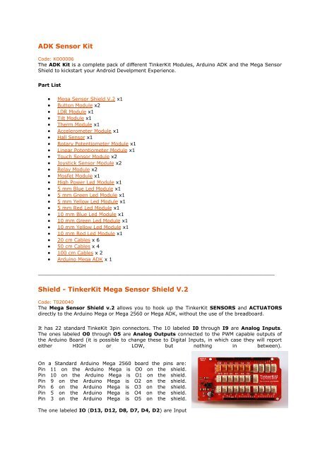
<strong>ADK</strong> <strong>Sensor</strong> <strong>Kit</strong>Code: K000006The <strong>ADK</strong> <strong>Kit</strong> is a complete pack of different Tinker<strong>Kit</strong> Modules, Arduino <strong>ADK</strong> and the <strong>Mega</strong> <strong>Sensor</strong><strong>Shield</strong> to kickstart your Android Develpment Experience.Part List <strong>Mega</strong> <strong>Sensor</strong> <strong>Shield</strong> <strong>V.2</strong> x1 Button Module x2 LDR Module x1 Tilt Module x1 Therm Module x1 Accelerometer Module x1 Hall <strong>Sensor</strong> x1 Rotary Potentiometer Module x1 Linear Potentiometer Module x1 Touch <strong>Sensor</strong> Module x2 Joystick <strong>Sensor</strong> Module x2 Relay Module x2 Mosfet Module x1 High Power Led Module x1 5 mm Blue Led Module x1 5 mm Green Led Module x1 5 mm Yellow Led Module x1 5 mm Red Led Module x1 10 mm Blue Led Module x1 10 mm Green Led Module x1 10 mm Yellow Led Module x1 10 mm Red Led Module x1 20 cm Cables x 6 50 cm Cables x 4 100 cm Cables x 2 Arduino <strong>Mega</strong> <strong>ADK</strong> x 1_____________________________________________________________________________<strong>Shield</strong> - Tinker<strong>Kit</strong> <strong>Mega</strong> <strong>Sensor</strong> <strong>Shield</strong> <strong>V.2</strong>Code: T020040The <strong>Mega</strong> <strong>Sensor</strong> <strong>Shield</strong> v.2 allows you to hook up the Tinker<strong>Kit</strong> SENSORS and ACTUATORSdirectly to the Arduino <strong>Mega</strong> or <strong>Mega</strong> 2560 or <strong>Mega</strong> <strong>ADK</strong>, without the use of the breadboard.It has 22 standard Tinke<strong>Kit</strong> 3pin connectors. The 10 labeled I0 through I9 are Analog Inputs.The ones labeled O0 through O5 are Analog Outputs connected to the PWM capable outputs ofthe Arduino Board (it is possible to change these to Digital Inputs, in which case they will reporteither HIGH or LOW, but nothing in between).On a Standard Arduino <strong>Mega</strong> 2560 board the pins are:Pin 11 on the Arduino <strong>Mega</strong> is O0 on the shield.Pin 10 on the Arduino <strong>Mega</strong> is O1 on the shield.Pin 9 on the Arduino <strong>Mega</strong> is O2 on the shield.Pin 6 on the Arduino <strong>Mega</strong> is O3 on the shield.Pin 5 on the Arduino <strong>Mega</strong> is O4 on the shield.Pin 3 on the Arduino <strong>Mega</strong> is O5 on the shield.The one labeled IO (D13, D12, D8, D7, D4, D2) are Input
Output pins capable of PWM, digitalRead and digitalWrite. They correspond to Digital 13, 12, 8, 7,4, 2.Module description: A green LED signals that the shield is correctly powered.The 4pin TWI socket allows communication to any device supporting the I2C protocol through theWire library on Arduino. 5V and Ground are provided on the socket.4 4pin SERIAL socket allows the board to communicate with other devices that support serialcommunication. 5V and Ground are provided on the socket for your convenience._______________________________________________________________________________The Pushbutton Module is possibly the simplest sensor available. Itdetects when a person or an object presses on its circular cap.Output:This module outputs 5v when the button is pressed and 0vwhen released. Pressing the button closes the circuit. When connectedto an input on the Arduino using the Tinker<strong>Kit</strong> <strong>Shield</strong>, you can expect avalue of 1023 while the button is pressed and 0 when released.Module Description: This module features a 12mm pushbutton , thestandard Tinker<strong>Kit</strong> 3pin connector, a green LED that signals that themodule is correctly powered and a yellow LED that is lit only when thebutton is pressed.This module is a SENSOR. The connector is an OUTPUT which mustbe connected to one of the INPUT connectors on the Tinker<strong>Kit</strong> <strong>Shield</strong>_____________________________________________________________________________LDR (or Light Dependant Resistor, or Photoresistor) is a variable resistor.Light falling on the sensor decreases its resistance.Output: This module outputs 5v when the sensor receives no light (the circuitis open) and 0v when exposed to bright light (the circuit is closed). Whenconnected to an input on the Arduino using the Tinker<strong>Kit</strong> <strong>Shield</strong>, you canexpect to read values from 0 to 1023.Module Description: This module features a Light Dependent Resistor, asignal amplifier, the standard Tinker<strong>Kit</strong> 3pin connector, a green LED thatsignals that the module is correctly powered and a yellow LED whosebrightness changes according to the amount of lightness.This module is a SENSOR. The connector is an OUTPUT which must beconnected to one of the INPUT connectors on the Tinker<strong>Kit</strong> <strong>Shield</strong>.____________________________________________________________________________The Tilt <strong>Sensor</strong> can detect when it is at an angle.
Output: This module contains two contacts and a small metal ball. Whenthe sensor is in its upright position, the ball bridges the two contacts,completing the circuit. When the board is tilted, the ball moves, and thecircuit opens. When upright, the module outputs 5V and when it is tilted, itoutputs 0V. When connected to an input on the Arduino using the Tinker<strong>Kit</strong><strong>Shield</strong>, you can expect to read a value of 1023 when in its upright positionand 0 when it is titled.Module description: this module features a Tilt <strong>Sensor</strong>, a signal amplifier,the standard Tinker<strong>Kit</strong> 3pin connector, a green LED that signals that themodule is correctly powered and a yellow LED that lights up when aconnection is made (the sensor is upright).This module is a SENSOR. The connector is an OUTPUT which must beconnected to one of the INPUT connectors on the Tinker<strong>Kit</strong> <strong>Shield</strong>._____________________________________________________________________________The Thermistor is a resistor whose resistance varies significantly (morethan in standard resistors) with temperature.Output: This module's output approches 5v as the temperature increases.As the temperature decreases, it approaches 0V. When connected to aninput on the Arduino using the Tinker<strong>Kit</strong> <strong>Shield</strong>, expect to read valuesbetween 0 and 1023(NB: any changes in the values will be slow and may not vary a greatdeal).Module Description: This module features a Thermistor, a signalamplifier, the standard Tinker<strong>Kit</strong> 3pin connector, a green LED that signalsthat the module is correctly powered and a yellow LED whose brightness changes according to thetemperature.This module is a SENSOR. The connector is an OUTPUT which must be connected to one of theINPUT connectors on the Tinker<strong>Kit</strong> <strong>Shield</strong>._____________________________________________________________________________An accelerometer is a device that measures acceleration. It is very commonin consumer electronics such as portable electronic devices and video gamecontrollers to detect movement using accelerometers.Output: This module outputs 0V to 5V on one of its two signal pins when itsG-force is changed (e.g. is moved). The value is approximately 2.5V whenthere is 0G on the X or Y axis. When you connect this module to the input onan Arduino using the Tinker<strong>Kit</strong> <strong>Shield</strong>, you can expect to read values between0 to 1023 while moving the module.Module description: On the back of the module you can find two signalamplifier and a green LED that signals that the module is correctly powered. The module is basedon the LIS344AL by ST Microelectronics, and is a three-axis acceremoter. You can get data aboutthe third axis (referred to as Z) by soldering a header to the thru-hole labeled "Z".This module is a SENSOR. The connector is an OUTPUT which must be connected to one of theINPUT connectors on the Tinker<strong>Kit</strong> <strong>Shield</strong>.
_____________________________________________________________________________A Hall sensor creates a voltage related to the magnetic field around the sensor.This can be used to detect distance from a nearby magnet. Hall sensors can alsobe used to detect the magnetic field induced in a wire or coil.Output: This module outputs 5v when a magnetic field (e.g. a human body) isclose to the sensor, and roughly 0v when there is nothing nearby. Whenconnected to an input on the Arduino using the Tinker<strong>Kit</strong> <strong>Shield</strong>, you can seevalues between 0 (no presence) and 1023 (presence detected).Module description: An Hall <strong>Sensor</strong> is mounted on a standard Tinker<strong>Kit</strong> board;on the back of the module you can find a signal amplifier, a green LED thatsignals that the module is correctly powered and a yellow LED whose brightnessdepends on the values output by the module.NB: There are exposed electrical contacts on the sensor surface - be careful to not touch the boardwith metallic objects, you may cause a short.This module is a SENSOR. The connector is an OUTPUT which must be connected to one of theINPUT connectors on the Tinker<strong>Kit</strong> <strong>Shield</strong>.____________________________________________________________________________A Potentiometer is a commonly used variable resistor. Turning the knob,you vary the output voltage between 0 and 5V. This value is sent throughthe middle pin of the pot.Output: This module outputs 5v when turned in one direction, and 0vwhen turned in the opposite way. When connected to an input on theArduino using the Tinker<strong>Kit</strong> <strong>Shield</strong>, you can expect to read values between0 and 1023.Module Description: This module features a 4k7 Ohm linearpotentiometer, a signal amplifier, the standard Tinker<strong>Kit</strong> 3pin connector, agreen LED that signals that the module is correctly powered and a yellowLED whose brightness changes according to the position of thepotentiometer.This module is a SENSOR. The connector is an OUTPUT which must beconnected to one of the INPUT connectors on the Tinker<strong>Kit</strong> <strong>Shield</strong>.____________________________________________________________________________A Linear Potentiometer is a commonly used variable resistor. It canoften be found as a volume controller on radios and TVs. By moving theslider you can vary the output voltage between 0 and 5V. This value is sentthrough the middle pin of the pot.Output: This module outputs 5v when the slider is at one end and 0vwhen moved in the opposite way. When connected to an input on theArduino using the Tinker<strong>Kit</strong> <strong>Shield</strong>, you can expect to read values goingfrom 0 to 1023.Module Description: this module features a 4k7 Ohm linear
potentiometer, a signal amplifier, the standard Tinker<strong>Kit</strong> 3pin connector, a green LED that signalsthat the module is correctly powered and a yellow LED whose brightness changes according to theposition of the potentiometer.This module is a SENSOR. The connector is an OUTPUT which must be connected to one of theINPUT connectors on the Tinker<strong>Kit</strong> <strong>Shield</strong>.____________________________________________________________________________The Touch <strong>Sensor</strong> is sensitive to skin contact.Output: This module normally outputs 0v, but when touched, sends 5v.When connected to an input on the Arduino using the Tinker<strong>Kit</strong> <strong>Shield</strong>,you will see 0 when there is no touch, and 1023 when touched.Module Description: on the back of the module you can find a signalamplifier, a capacitor, a QT 100A single touch controller, a green LEDthat signals that the module is correctly powered and a yellow LEDwhose brightness depends on the values output by the module.Please note this device performs an auto calibration when it is turnedon, so if someone is touching the switch surface when it is turned on it will not work. To reset,cycle power and make sure no one is touching it as you restart.This module is a SENSOR. The connector is an OUTPUT which must be connected to one of theINPUT connectors on the Tinker<strong>Kit</strong> <strong>Shield</strong>.____________________________________________________________________________The Joystick module is similar to analog joysticks found in gamepads. It is made made bymounting two potentiometers at a 90 degrees angle. The potentiometers are connected to a shortstick centered by springs.Output: This module will output roughly 2.5 volts from both outputswhen in its resting position. Moving the stick will cause the outputs tochange from 0v to 5v depending on its direction. If you connect thismodule to an Arduino through the Tinkerkit <strong>Shield</strong>, you can expect toread a value of roughly 512 in its resting position (expect smallvariations due to tiny imprecisions of the springs and mechanism) Whenyou move the joystick you should see the values change from 0 to 1023depending on its position.Module Description: This module features two 4k7 Ohm linearpotentiometers, two standard Tinker<strong>Kit</strong> 3pin connector, two signalamplifiers, a green LED that signals that the module is correctly poweredand two yellow LED whose brightness depends on the values output by the module.This module is a SENSOR. Its connectors are OUTPUTs which must be be connected to two of theINPUT connectors on the Tinker<strong>Kit</strong> <strong>Shield</strong>.____________________________________________________________________________
A relay is an electrically operated switch that allows you to turn on oroff a circuit using voltage and/or current much higher than the Arduinocould handle. There is no connection between the low voltage circuitoperated by Arduino and the high power circuit. The relay protects eachcircuit from each other.Warning: We don't recommend you operate circuits powered at morethan 24V without the supervision of an expert.Input: The relay is a simple mechanical on/off switch. It activates whenthe input reaches 5v and turns off when the input is 0v. You can control itthough the digitalWrite() function on Arduino.The module provides three connections labeled COM, NC and NO. NC stands for "NORMALLYCLOSED". This means that when the relay has no signal (LOW or 0V from an Arduino), theconnected circuit wil be active; conversely, if you apply 5V or pull the pin HIGH, it will turn theconnected circuit off. NO stands for "NORMALLY OPEN", and functions in the opposite way; whenyou apply 5V the circuit turns on, and at 0V the circuit turns off. Relays can replace a manualswitch. Remove the switch and connect its wires toCOM and NO. When the relay is activated thecircuit is closed and current can flow to the device you are controlling.Module Description: this module features an 250v 10A mounted on a 2 module Tinker<strong>Kit</strong> board,one standard Tinker<strong>Kit</strong> 3pin connector, one transistor, a green LED that signals that the module iscorrectly powered and an yellow LED that indicates when the relay is active.This module is an ACTUATOR. The connector is an INPUT which must be connected to one of theOUTPUT connectors on the Tinker<strong>Kit</strong> <strong>Shield</strong>._____________________________________________________________________________This module switches a high current load using a high power transistor.Unlike a mechanical relay, this is capable of high speed switching for usewith PWM.Input: This module lets you control devices operating at a maximun of24VDC with an Arduino pin. To wire the module, connect the power supplyfor your device (max 24 V) to the V+ and GND terminals. Connect thedevice to M+ and M-. Be aware of your circuit's polarity, you coulddamage your components if it is not wired correctly.Module Description: This module features an IRF520 power MOSFETtransistor, a kick-back diode, a standard Tinker<strong>Kit</strong> 3pin connector,a signalamplifier, a green LED that signals that the module is correctly poweredand one yellow LED whose brightness depends on the input signal received by the module.This module is a ACTUATOR. The connector is an INPUT that must be connected to an OUTPUTon the Tinker<strong>Kit</strong> <strong>Shield</strong>.
_____________________________________________________________________________The Power LED is an actuator. Five ultra-bright LEDs can be powered from anArduino pin. Input: Arduino provides a maximum of 40 mA per pin, enoughto light up the five LEDs using the DigitalWrite() and AnalogWrite() functions.Module description: This module features Five AWT801-S LEDs fromSeoul Semi Conductor, the standard Tinker<strong>Kit</strong> 3pin connector and a greenLED that signals that the module is correctly powered and a yellow LED that islit only when the LED is lit. A resistor limits the voltage from the Arduino,protecting the lights.This module is an ACTUATOR. The connector is an INPUT which must beconnected to an OUTPUT connector on the Tinker<strong>Kit</strong> <strong>Shield</strong>._______________________________________________________________________________The LED is possibly the simplest actuator available. It’s a low power light sourceavailable in many colors. It lights up when powered from an Arduino pin.Input: Arduino provides a maximum of 40 mA per pin; this is enough to lightup the LED through the digitalWrite() and analogWrite() functions.Module description: This module features a 5mm Blue Light Emitting Diode,the standard Tinker<strong>Kit</strong> 3pin connector and a green LED that signals that themodule is correctly powered and a tiny yellow LED that shows the currentbrightness of the blue LED. A resistor provides the optimal amount of currentwhen connected to an Arduino.This module is an ACTUATOR therefore the connector is an INPUT that need tobe connected to one of the OUTPUT connectors on the Tinker<strong>Kit</strong> <strong>Shield</strong>.____________________________________________________________________________The LED is possibly the simplest actuator available. It’s a low power lightsource available in many colors. It lights up when powered from an Arduinopin.Input: Arduino provides a maximum of 40 mA per pin; this is enough tolight up the LED through the digitalWrite() and analogWrite() functions.Module description: this module features a 5mm Green Light EmittingDiode, the standard Tinker<strong>Kit</strong> 3pin connector and a green LED that signalsthat the module is correctly powered and a tiny yellow LED that shows thecurrent brightness of the main green LED. A resistor provides the optimalamount of current when connected to an Arduino.This module is an ACTUATOR therefore the connector is an INPUT that needto be connected to one of the OUTPUT connectors on the Tinker<strong>Kit</strong> <strong>Shield</strong>.
_______________________________________________________________________________The LED is possibly the simplest actuator available. It’s a low power light sourceavailable in many colors. It lights up when powered from an Arduino pin.Input: Arduino provides a maximum of 40 mA per pin; this is enough to light upthe LED through the digitalWrite() and analogWrite() functions.Module description: this module features a 5mm Yellow Light Emitting Diode,the standard Tinker<strong>Kit</strong> 3pin connector and a green LED that signals that themodule is correctly powered and a tiny yellow LED that shows the currentbrightness of the yellow LED. A resistor provides the optimal amount of currentwhen connected to an Arduino.This module is an ACTUATOR therefore the connector is an INPUT that need tobe connected to one of the OUTPUT connectors on the Tinker<strong>Kit</strong> <strong>Shield</strong>._______________________________________________________________________________The LED is possibly the simplest actuator available. It’s a low power light sourceavailable in many colors. It lights up when powered from an Arduino pin.Input: Arduino provides a maximum of 40 mA per pin; this is enough to lightup the LED through the digitalWrite() and analogWrite() functions.Module description: This module features a 5mm Red Light Emitting Diode,the standard Tinker<strong>Kit</strong> 3pin connector and a green LED that signals that themodule is correctly powered and a tiny yellow LED that shows the currentbrightness of the red LED. A resistor provides the optimal amount of currentwhen connected to an Arduino. This module is an ACTUATOR therefore theconnector is an INPUT that need to be connected to one of the OUTPUTconnectors on the Tinker<strong>Kit</strong> <strong>Shield</strong>._______________________________________________________________________________The LED is possibly the simplest actuator available. It’s a low power light sourceavailable in many colors. It lights up when powered from an Arduino pin.Input: Arduino provides a maximum of 40 mA per pin; this is enough to light upthe LED through the digitalWrite() and analogWrite() functions.Module description: this module features a 10mm Green Light Emitting Diode,the standard Tinker<strong>Kit</strong> 3pin connector and a green LED that signals that themodule is correctly powered and a tiny yellow LED that shows the currentbrightness of the large green LED. A resistor provides the optimal amount ofcurrent when connected to an Arduino. This module is an ACTUATOR thereforethe connector is an INPUT that need to be connected to one of the OUTPUTconnectors on the Tinker<strong>Kit</strong> <strong>Shield</strong>._____________________________________________________________________________The LED is possibly the simplest actuator available. It’s a low power lightsource available in many colors. It lights up when powered from an Arduinopin.Input: Arduino provides a maximum of 40 mA per pin; this is enough to lightup the LED through the digitalWrite() and analogWrite() functions.
Module description: this module features a 10mm Blue Light Emitting Diode, the standardTinker<strong>Kit</strong> 3pin connector and a green LED that signals that the module is correctly powered and atiny yellow LED that shows the current brightness of the blue LED. A resistor provides the optimalamount of current when connected to an Arduino. This module is an ACTUATOR therefore theconnector is an INPUT that need to be connected to one of the OUTPUT connectors on theTinker<strong>Kit</strong> <strong>Shield</strong>._____________________________________________________________________________The LED is possibly the simplest actuator available. It’s a low power lightsource available in many colors. It lights up when powered from an Arduinopin.Input: Arduino provides a maximum of 40 mA per pin; this is enough to lightup the LED through the digitalWrite() and analogWrite() functions.Module description: this module features a 10mm Yellow Light EmittingDiode, the standard Tinker<strong>Kit</strong> 3pin connector and a green LED that signalsthat the module is correctly powered and a tiny yellow LED that shows thecurrent brightness of the yellow LED. A resistor provides the optimal amountof current when connected to an Arduino.This module is an ACTUATOR therefore the connector is an INPUT that need to be connected toone of the OUTPUT connectors on the Tinker<strong>Kit</strong> <strong>Shield</strong>._____________________________________________________________________________The LED is possibly the simplest actuator available. It’s a low power lightsource available in many colors. It lights up when powered from anArduino pin.Input: Arduino provides a maximum of 40 mA per pin; this is enough tolight up the LED through the digitalWrite() and analogWrite()functions.Module description: This module features a 10mm Red Light EmittingDiode, the standard Tinker<strong>Kit</strong> 3pin connector and a green LED that signalsthat the module is correctly powered and a tiny yellow LED that shows thecurrent brightness of the red LED. A resistor provides the optimal amountof current when connected to an Arduino.This module is an ACTUATOR therefore the connector is an INPUT that need to be connected toone of the OUTPUT connectors on the Tinker<strong>Kit</strong> <strong>Shield</strong>.
_____________________________________________________________________________20 cm long wires for the Tinker<strong>Kit</strong> with a 3 pin jumper on both sides50 cm long wires for the Tinker<strong>Kit</strong> with a 3 pin jumper on both sides.100 cm long wires for the Tinker<strong>Kit</strong> with a 3 pin jumper on both sides_____________________________________________________________________________Arduino <strong>ADK</strong> Rev3Code: A000069The Arduino <strong>ADK</strong> R3 is a microcontroller board based on theATmega2560 (datasheet). It has a USB host interface to connect withAndroid based phones.It is compatible with Android's Accessory Development <strong>Kit</strong> examples. Ithas 54 digital input/output pins (of which 14 can be used as PWMoutputs), 16 analog inputs, 4 UARTs (hardware serial ports), a 16 MHzcrystal oscillator, a USB connection, a power jack, an ICSP header, anda reset button.The <strong>ADK</strong> is based on the <strong>Mega</strong> 2560. Plus it has an USB Host circuit thatenable this board to communicate with USB Devices, and give them
power supply.Additional features coming with the R3 version are:ATmega16U2 instead 8U2 as USB-to-Serial converter.1.0 pinout: added SDA and SCL pins for TWI communication placed near to the AREF pinand two other new pins placed near to the RESET pin, the IOREF that allow the shields toadapt to the voltage provided from the board and the second one is a not connected pin,that is reserved for future purposes.stronger RESET circuit.