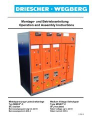
Montage- und Betriebsanleitung Operation and Assembly Instructions
Montage- und Betriebsanleitung Operation and Assembly Instructions
Montage- und Betriebsanleitung Operation and Assembly Instructions

Erfolgreiche ePaper selbst erstellen
Machen Sie aus Ihren PDF Publikationen ein blätterbares Flipbook mit unserer einzigartigen Google optimierten e-Paper Software.
DRIESCHER • WEGBERG<br />
Kuppeln der Auslösewellen des Anti-<br />
Berst-Systems bei Einzelfeldlieferung<br />
LDTM–Schaltfelder mit Anti-Berst-System sind<br />
unterein<strong>and</strong>er mit je einer Kupplung versehen<br />
(Bild 3).<br />
Bei im Werk komplettierten Anlagen ist die<br />
Welle bereits gekuppelt.<br />
Vor Inbetriebnahme der Schaltanlage ist daher darauf<br />
zu achten, dass die Kupplung der Auslösewellen<br />
zweier benachbarter Schaltfelder funktionstüchtig ist.<br />
Achten Sie darauf, daß die Auslösewellen aller<br />
Schaltfelder vor Inbetriebnahme gekuppelt sein<br />
müssen, um die Funktion des Anti-Berst-Systems zu<br />
sichern. Für Schäden <strong>und</strong> Betriebsstörungen, die<br />
sich aus dem Nichtkuppeln der Auslösewellen<br />
ergeben, übernehmen wir keine Haftung!<br />
Nach <strong>Montage</strong> der Schaltanlage Zylinderschraube<br />
des Kuppelteils lösen <strong>und</strong> Kuppelteil nach links in<br />
das benachbarte Schaltfeld schieben (Bild 1).<br />
Kuppelteil über die Auslösewelle bis vor spürbaren<br />
Anschlag schieben, auf Leichtgängigkeit achten,<br />
Zylinderschraube vor der Auslösewelle in Kuppelteil<br />
fest <strong>and</strong>rehen (Bild 2).<br />
Auslösewelle auf Leichtgängigkeit prüfen.<br />
Die Auslösemechanik des Anti-Berst-Systems<br />
wurde im Werk optimal eingestellt. Nehmen Sie daher<br />
keine Veränderungen an der Auslösemechanik<br />
vor, da es ansonsten zu Fehlverhalten oder Nichtansprechen<br />
führen kann.<br />
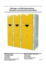
24 LDTM<br />
Coupling of the tripping shafts of the<br />
ABS when supplying single cubicles.<br />
LDTM cubicles with an Anti-Burst-System are interlinked<br />
by one coupling each (Figure 3).<br />
In case of switchgear that have been completed<br />
in the factory the shaft has already<br />
been coupled.<br />
Therefore, before setting the switchgear to work<br />
make sure that the coupling of the tripping shafts in<br />
two adjacent cubicles is in a perfect functional state.<br />
Make sure that the tripping shafts of all cubicles<br />
are coupled before commissioning in order to<br />
guarantee the function of the Anti-Burst-System.<br />
For damages <strong>and</strong> troubles during operation resulting<br />
from the lack of described coupling of the tripping<br />
shafts we assume no responsibility!<br />
After switchgear assembly, loosen the cylindrical<br />
screw at the coupling part <strong>and</strong> move the coupling<br />
part to the left into the adjacent cubicle (Figure 1).<br />
Move the coupling part across the tripping shaft up<br />
to a noticeable stop, pay attention to an easy<br />
movement <strong>and</strong> tighten solidly the cylindrical screw<br />
situated in front of the tripping shaft in the coupling<br />
part (Figure 2).<br />
Check the easy movement of the tripping shaft.<br />
The triggering of the Anti-Burst-System was<br />
optimum adjusted at factory. Never change these<br />
settings, because that could cause failures or a<br />
non-operation.