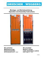
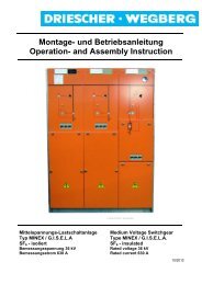
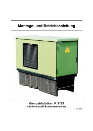
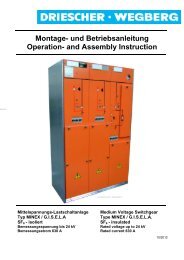
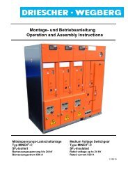
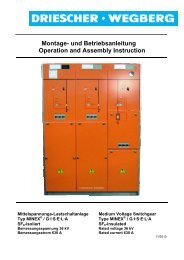
Montage- und Betriebsanleitung Operation and Assembly Instructions
Montage- und Betriebsanleitung Operation and Assembly Instructions
Montage- und Betriebsanleitung Operation and Assembly Instructions

Erfolgreiche ePaper selbst erstellen
Machen Sie aus Ihren PDF Publikationen ein blätterbares Flipbook mit unserer einzigartigen Google optimierten e-Paper Software.
DRIESCHER • WEGBERG<br />
Optionale Ausstattung<br />
Motorantrieb (Option)<br />
Der Motorantrieb übernimmt die Funktion der Schaltkurbel.<br />
Die gr<strong>und</strong>sätzliche mechanische Wirkungsweise<br />
des Schalterantriebes bleibt hiervon unberührt.<br />
Ebenso bestehen die Verriegelungen in gleicher<br />
Art.<br />
Mit Motorantrieben ausgerüstete Lasttrennschalter<br />
sind über eine entsprechende Steuerung (Option)<br />
ein- <strong>und</strong> ausschaltbar.<br />
Der Motorantrieb mit Getriebe ist hinter dem rechten<br />
Seitenholm der Felder angebracht. Er treibt über<br />
einen Kettenradantrieb die Antriebswelle an <strong>und</strong><br />
schaltet den Schalter ein bzw. aus.<br />
Der Schaltwinkel für das EIN- / AUS - Schalten des<br />
Lasttrennschalters ist werksseitig eingestellt.<br />
Der Motorantrieb ist für den Anschluss an Gleichspannung<br />
ausgelegt. Für den Betrieb mit Wechselspannung<br />
muss ein Gleichrichter eingesetzt werden.<br />
Technische Leistungsdaten: Die Motorspannung ist<br />
auf dem Typenschild der Anlage angegeben.<br />
Netzspannung<br />
[V]<br />
Max. Stromaufnahme<br />
[A]<br />
Max. Leistungsaufnahme<br />
[W]<br />
Laufzeit<br />
EIN/AUS<br />
Ca. [s]<br />
34 LDTM<br />
Optional Equipment<br />
Motor mechanism (Option)<br />
The motor mechanism functions as a switch<br />
crank. The basic mechanical function of the switch<br />
mechanism is not influenced by this. Also the<br />
interlockings remain unchanged.<br />
Switch-disconnectors equipped with motor mechanisms<br />
can be switched ON <strong>and</strong> OFF via a<br />
corresponding control device (option).<br />
The motor mechanism with gear is installed behind<br />
the lateral rail at right h<strong>and</strong> side of the cubicles.<br />
It actuates the drive shaft by means of a<br />
chain-wheel drive the drive shaft <strong>and</strong> operates the<br />
switch-disconnector ON/OFF.<br />
The switching angle for the ON/OFF switching of<br />
the switch-disconnector is predetermined in the<br />
factory. The motor mechanism is designed for<br />
direct current supply. For the operation with alternating<br />
current a rectifier has to be used.<br />
Technical data: The motor voltage value is indicated<br />
on the switchgear nameplate.<br />
System<br />
voltage [V]<br />
max<br />
input current<br />
[A]<br />
max.<br />
power input<br />
[W]<br />
cycle time<br />
ON/OFF<br />
approx.<br />
[sec.]<br />
230 AC 0,22 40 10/7 230 AC 0,22 40 10/7<br />
115 AC 0,39 43 11/8 115 AC 0,39 43 11/8<br />
220 DC 0,28 64 11/9 220 DC 0,28 64 11/9<br />
110 DC 0,36 42 12/10 110 DC 0,36 42 12/10<br />
60 DC 0,66 41 11/8 60 DC 0,66 41 11/8<br />
48 DC 0,69 34 13/10 48 DC 0,69 34 13/10<br />
24 DC 1,41 34 13/10 24 DC 1,41 34 13/10<br />
Die elektrischen Betätigungselemente sind dem<br />
Schaltfeld zugeordnet; entweder oberhalb der<br />
Schaltanlage in einem gesonderten Relaiskasten<br />
oder in der Schaltfeldblende.<br />
Den Stromlaufplan zur Steuerung des Motorantriebes<br />
finden Sie in den der Schaltanlage beigefügten<br />
Schaltungsunterlagen.<br />
Bei Anbau <strong>und</strong> Funktionskontrolle des Motorantriebes<br />
steht die Schaltanlage in unserem Werk<br />
auf einer ebenen Fläche.<br />
Es kann vorkommen, dass je nach Bodenbeschaffenheit<br />
vor Ort, die Motorendschalter nicht<br />
mehr richtig positioniert sind.<br />
Beschädigung der Anlage möglich! Aus diesem<br />
Gr<strong>und</strong> ist es erforderlich, vor der ersten Inbetriebnahme<br />
die Positionierung der Endschalter zu<br />
überprüfen.<br />
The electrical operating elements are coordinated<br />
to the cubicle; either above the switchgear in a<br />
separate relay box or in the cubicle cover.<br />
You can find the circuit diagram for the control of<br />
the motor mechanism within the circuit documentation<br />
which is attached to the switchgear.<br />
For installation <strong>and</strong> function test of the motor<br />
mechanism in our factory the switchgear is st<strong>and</strong>ing<br />
on a flat area. Depending on the existing gro<strong>und</strong><br />
conditions at site it could be possible that the motor<br />
limit switches are no longer in the correct position.<br />
Damage of the Switchgear is possible! Therefore<br />
it is necessary to check the position of the limit<br />
switches before 1 st commissioning.