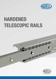
NADELLA – Telescopic-Line LS1002EN
- Keine Tags gefunden...

Sie wollen auch ein ePaper? Erhöhen Sie die Reichweite Ihrer Titel.
YUMPU macht aus Druck-PDFs automatisch weboptimierte ePaper, die Google liebt.
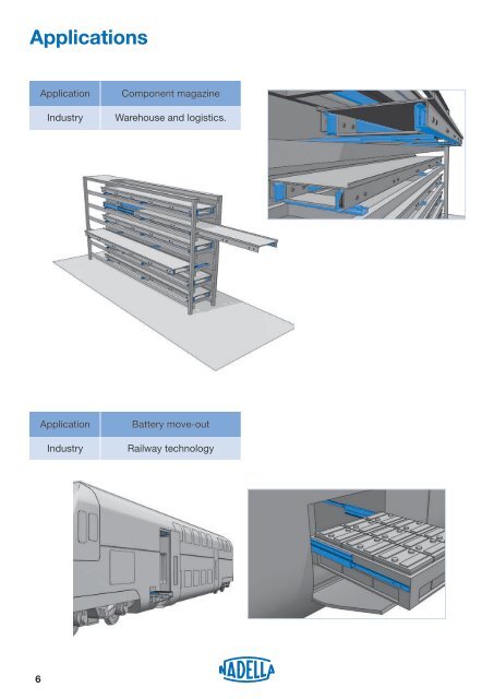
Applications<br />
Application<br />
Industry<br />
Component magazine<br />
Warehouse and logistics.<br />
Application<br />
Industry<br />
Battery move-out<br />
Railway technology<br />
6