CAT-NADNL22EN - Linear Guide Systems
Nadella Linear Guide Systems Catalog
Nadella Linear Guide Systems Catalog

You also want an ePaper? Increase the reach of your titles
YUMPU automatically turns print PDFs into web optimized ePapers that Google loves.
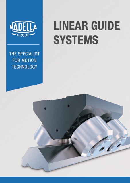
LINEAR GUIDE<br />
SYSTEMS<br />
THE SPECIALIST<br />
FOR MOTION<br />
TECHNOLOGY
THE SPECIALIST FOR MOTION TECHNOLOGY<br />
Nadella Group is an expert system partner for all areas of motion technology,<br />
with specialized manufacturing companies and a worldwide sales network.<br />
Wherever innovative ideas, customized solutions, precision and reliability are required,<br />
developers and design engineers rely on products and solutions from the Nadella Group.<br />
BRANDS AND PRODUCTS OVERVIEW<br />
<strong>Linear</strong> <strong>Guide</strong>s<br />
Telescopic<br />
Rails<br />
<strong>Linear</strong><br />
Modules<br />
<strong>Linear</strong> Axes and<br />
<strong>Systems</strong><br />
Circular<br />
<strong>Systems</strong><br />
Bearings and<br />
Cam Followers<br />
Adjusting<br />
Nuts & Rings<br />
Rod Ends and<br />
Spherical Plain Bearings<br />
Clevises and<br />
Ball/Axial Joints<br />
Precision<br />
Ball Screws<br />
Rolled<br />
Ball Screws<br />
MILESTONES KEY NUMBERS APPLI<strong>CAT</strong>ION SECTORS<br />
1930<br />
NADELLA foundation in France<br />
1958<br />
Founding of NADELLA GMBH in Germany<br />
1963<br />
Founding of NADELLA S.P.A. in Italy<br />
8<br />
1<br />
Group<br />
manufacturing plants<br />
1984<br />
Start of development and sale of Nadella <strong>Linear</strong><br />
2012<br />
New Nadella subsidiaries in China and USA<br />
2014<br />
Acquisition of DURBAL<br />
14<br />
main locations<br />
Italy, Germany, France,<br />
Poland, Spain, United<br />
Kindom, U.S.A.,China<br />
2018<br />
Acquisition of CHIAVETTE UNIFI<strong>CAT</strong>E<br />
2019<br />
Founding of Nadella Motion Technology Changxing Co.<br />
Ltd.<br />
leading the way in the international markets<br />
in over<br />
60<br />
countries<br />
2020<br />
New Nadella subsidiaries in France and Spain<br />
Acquisition of SHUTON and IPIRANGA<br />
2 |<br />
2021<br />
Acquisition of DAMO<br />
2022<br />
Orchestra enters in Nadella Group<br />
for more than<br />
90<br />
years
SUMMARY<br />
PAGE 4<br />
1.0 COMPANY<br />
0<br />
PAGE 8<br />
PAGE 16<br />
PAGE 36<br />
PAGE 46<br />
PAGE 70<br />
PAGE 82<br />
PAGE 102<br />
2.0 PRODUCT OVERVIEW<br />
3.0 HEAVY-LINE<br />
• For high loads and difficult ambient conditions<br />
• Robust guide rollers with tapered roller bearings<br />
• <strong>Guide</strong> rail for fixed and floating bearings<br />
4.0 ROLBLOC<br />
• For extremely high loads and robust applications<br />
• Up to 15 t per carriage<br />
• High compensation for a simple mounting<br />
5.0 V-LINE<br />
• Full and half rail in steel with V profile<br />
• For all applications and loads<br />
• Very extensive design possibilities<br />
6.0 MULTI-MOTION-LINE<br />
• Circular rails based on the profiles of V-Line<br />
• Circular rails, oval circuits and ring circuits<br />
7.0 C-LINE<br />
• <strong>Guide</strong> rollers for fixed and floating bearing constructions<br />
• High speeds and acceleration<br />
• Maintenance-free due to integrated lubrication system<br />
8.0 BASE-LINE<br />
• Starter type line for light and medium loads<br />
• Low and space-saving design<br />
NX<br />
NX<br />
NX<br />
NX<br />
NX<br />
PAGE 122 9.0 FLEXI-LINE 645<br />
• Dimensions according DIN to 645 with flexible configuration<br />
• For light and medium loads<br />
• Ready-to-install<br />
NX<br />
PAGE 128<br />
PAGE 146<br />
10.0 U-LINE<br />
• For light and medium loads<br />
• Compact design of U-Line guides with inside carriage<br />
11.0 TECHNICAL FEATURES<br />
NX<br />
| 3
4 |
PRODUCT<br />
OVERVIEW<br />
1<br />
PAGE 06<br />
PAGE 07<br />
PAGE 08<br />
PAGE 09<br />
PAGE 10<br />
PAGE 11<br />
1.1 HEAVY-LINE<br />
1.2 ROLBLOC<br />
1.3 V-LINE<br />
1.4 MULTI-MOTION-LINE<br />
1.5 C-LINE<br />
1.6 BASE-LINE<br />
PAGE 12 1.7 FLEXI-LINE 645<br />
PAGE 13<br />
1.8 U-LINE<br />
| 5
PRODUCT OVERVIEW 1.1<br />
HEAVY-LINE<br />
For medium-heavy loads<br />
PAGE<br />
<strong>Guide</strong> rails GU ... M, GU ... MT 18<br />
<strong>Guide</strong> rollers RKU 19<br />
<strong>Guide</strong> wheels FKU 20<br />
Floating guide rollers RKUL 21<br />
Lubricator LUBU 22<br />
<strong>Guide</strong> pins SAG 23<br />
For medium-heavy loads / dirty environment<br />
<strong>Guide</strong> GP ... MC / M 24<br />
<strong>Guide</strong> rails GP ... M 25<br />
<strong>Guide</strong> rollers PK 26<br />
<strong>Guide</strong> wheels FK 27<br />
<strong>Guide</strong> rollers GC 28<br />
Cam followers FG / FGU 30<br />
Lubricator LUBP 32<br />
6 |
1.2<br />
ROLBLOC<br />
For medium-heavy loads / dirty environment<br />
PAGE<br />
<strong>Guide</strong> rails GU ... M, GU ... MT 39<br />
Carriages BL 40<br />
Carriages BL ... DS with discharge system 41<br />
Adjustment plates PR 42<br />
Wipers RPT 43<br />
Lubricator LUBL for Rolbloc 43<br />
1.3<br />
V-LINE<br />
For any application<br />
PAGE<br />
<strong>Guide</strong> rails FS ... MT 48<br />
<strong>Guide</strong> rails FS ... M 49<br />
<strong>Guide</strong> rails FSH ... MT, FSX ... MT 50<br />
<strong>Guide</strong> rails FSH ... M, FSX ... M 51<br />
<strong>Guide</strong> rails FSHZ - FSXZ 52<br />
<strong>Guide</strong> rollers FR ... EU 54<br />
<strong>Guide</strong> rollers FR ... EU AS, FR ... EU AZ 55<br />
<strong>Guide</strong> rollers FRN ... EI 56<br />
| 7
PRODUCT OVERVIEW 1.3<br />
V-LINE<br />
For medium-heavy loads<br />
PAGE<br />
<strong>Guide</strong> rollers RKY, RKX 57<br />
<strong>Guide</strong> wheels FKY, FKX 58<br />
Floating guide rollers FRL ... EU 59<br />
Floating guide rollers RKXL, RKYL 60<br />
Spacers for guide rollers FS / FSH 61<br />
Pinion PZ 62<br />
Lubricator LUBY, LUBX, LUBZ 63-64-65<br />
1.4<br />
MULTI-MOTION-LINE<br />
For any application<br />
PAGE<br />
Circular rails FSR ... M 73<br />
Alignment blocks for FSR 74<br />
Oval circuit FSRO 75<br />
Ring circuit FSRQ 76<br />
Carriages with fixed guide rollers T4R 77<br />
Steering carriage T4R ... 78<br />
Lubricator LUBR 79<br />
8 |
1.5<br />
C-LINE<br />
For light-medium loads<br />
PAGE<br />
<strong>Guide</strong> rails NT 84<br />
<strong>Guide</strong> rails LS 84<br />
<strong>Guide</strong> rollers RT 85<br />
<strong>Guide</strong> rollers RTL 86<br />
<strong>Guide</strong> rollers RCS 87<br />
<strong>Guide</strong> rollers RAS 88<br />
Carriages C3 RT, C3 RTL AND C3 RTY 90<br />
Carriages C4 RT, C4 RTL AND C4 RTY 91<br />
Carriages C3 RCS, C3 RAS AND C3 RYS 90<br />
Carriages C5 RT, C5 RTL AND C5 RTY 92<br />
Carriages C6 RT, C6 RTL AND C6 RTY 93<br />
| 9
PRODUCT OVERVIEW 1.6<br />
BASE-LINE<br />
For medium loads and corrosive environment<br />
PAGE<br />
<strong>Guide</strong> rails DC 105<br />
<strong>Guide</strong> rails C 106<br />
<strong>Guide</strong> rollers PFV<br />
107-<br />
108<br />
<strong>Guide</strong> rollers RKO 110<br />
Carriages T4 PFV 111<br />
Wiper NAID 112<br />
Lubricator LUBC 113<br />
For light to medium loads<br />
<strong>Guide</strong> rails FWS 114<br />
<strong>Guide</strong> rails FWH 115<br />
<strong>Guide</strong> rollers FR ... EU 117<br />
<strong>Guide</strong> rollers FR ... EU AS, FR ... EU AZ 117<br />
Floating guide rollers FRL ... EU 118<br />
Carriage T4 FR 119<br />
10 |
FLEXI-LINE 645<br />
For light-medium loads<br />
1.7<br />
PAGE<br />
<strong>Guide</strong> rails FWN 125<br />
Carriage TA4, TB4 126<br />
1.8<br />
U-LINE<br />
For light-medium loads<br />
PAGE<br />
<strong>Guide</strong> rails LM 134<br />
<strong>Guide</strong> rollers RCL, RCP, PFV 135<br />
<strong>Guide</strong> rollers RAL 136<br />
<strong>Guide</strong> rollers GLA 137<br />
Carriage C3 RCL, C3 RAL,C3 RYL 138<br />
Carriage C4 RCL, C4 RAL, C4 RYL 139<br />
Carriage T4 RCL, T4 RCP, T4 PFV + T4 RAL, T4 RY 140<br />
Lubricator LUBM 141<br />
<strong>Guide</strong> rails LML 142<br />
Carriage C3 RCL 16 NX + Carriage C4 RCL 16 NX 143<br />
| 11
12 |
HEAVY-LINE<br />
2<br />
PAGE 14<br />
PAGE 20<br />
PAGE 28<br />
PAGE 31<br />
2.1 SISTEMI GU<br />
For medium-heavy loads<br />
• <strong>Guide</strong> rails GU ... M, GU ... MT<br />
• <strong>Guide</strong> rollers RKU<br />
• <strong>Guide</strong> wheels FKU<br />
• Floating guide rollers RKUL<br />
• Lubricator LUBU<br />
• <strong>Guide</strong> pins SAG<br />
• <strong>Guide</strong> rollers combinations<br />
2.2 GP SYSTEM<br />
For medium-heavy loads / dirty environment<br />
• <strong>Guide</strong> rails GP ... MC<br />
• <strong>Guide</strong> rails GP ... M<br />
• <strong>Guide</strong> rollers PK<br />
• <strong>Guide</strong> wheels FK<br />
• <strong>Guide</strong> rollers GC<br />
• Cam followers FG (needle) and FGU (roller)<br />
• Lubricator LUBP<br />
2.3 GUIDE ROLLERS COMBINATIONS<br />
2.4 MOUNTING EXAMPLES<br />
| 13
HEAVY-LINE – GU SYSTEM<br />
GUIDE RAILS GU ... M, GU ... MT<br />
The longitudinal slot, made with + 0.05 tolerance, permits using reference elements SAG for guide positioning.<br />
90°<br />
± 10'<br />
G<br />
H<br />
c<br />
h<br />
g<br />
H<br />
sm<br />
GU ... MT<br />
D<br />
+ 0.05<br />
b<br />
I1<br />
I<br />
GU ... M<br />
S<br />
L<br />
90° ± 5' 90° ± 5'<br />
90° ± 10'<br />
90° 90°<br />
± ± 5' 10'<br />
G<br />
0.02 AB<br />
G<br />
c<br />
H<br />
g<br />
H<br />
c<br />
h<br />
h<br />
g<br />
+ 0.05<br />
b<br />
A<br />
D<br />
D<br />
b + 0.05 + 0.05<br />
b<br />
0.1 B<br />
I1<br />
I<br />
I1<br />
I<br />
S<br />
B SS<br />
0.02<br />
L<br />
B<br />
L<br />
sm<br />
sm<br />
Type Dimensions (mm) Weight 1)<br />
H<br />
0.02 AB<br />
h S D G<br />
0.02 AB<br />
g b c sm l l 1<br />
(kg/m)<br />
H<br />
± 0.05 c ± 0.05 ± H0.05<br />
h<br />
+ 0.1<br />
c<br />
h<br />
+ 0.05 ± 0.05<br />
GU 28 MT 19 11 28.8 5.5 10 5.7 10 2.5 0.7 x 45° 90 30 1.97<br />
A GU 35 MTb + 0.05 23.9<br />
0.1<br />
15.7<br />
B<br />
35.5<br />
A<br />
6.6b 11<br />
0.1<br />
6.8<br />
B<br />
10 3.8 1 x 45° 90 30 3.35<br />
GU 50 MT 35.5 21 50.8 11 18 11 16 4.3 1 x 45° 90 30 6.89<br />
B S<br />
0.02 B B S<br />
0.02 B<br />
Max. length in single element L = 6000 mm.<br />
Longer rails are made by juxtaposing several elements with ground end.<br />
1) Weight without holes<br />
Type Dimensions (mm) Weight 2)<br />
H h S D G g b c l l 1<br />
(kg/m)<br />
± 0.05 ± 0.05 ± 0.05 + 0.1<br />
+ 0.05 ± 0.05<br />
GU 28 M 18 10 28 5.5 10 5.7 10 2 90 30 1.8<br />
GU 35 M 23 15 35 6.6 11 6.8 10 3.3 90 30 3.2<br />
GU 50 M 34.5 20 50 11 18 11 16 3.8 90 30 6.8<br />
Max. length in single element L = 4020 mm.<br />
Longer rails are made by juxtaposing several elements with ground end.<br />
2) Weight without holes<br />
RAILS FINISHING<br />
• Drawn, induction hardened and sandblasted tracks (MT)<br />
• Drawn, induction hardened and ground (M)<br />
• Induction hardening on raceways only<br />
HOLE LAYOUT<br />
• Holes according to catalogue (SB)<br />
• Finishes to drawing (NZ)<br />
• Without holes (NF)<br />
OPTIONAL FEATURES<br />
• Ground one end: side of the first hole (1R), side of the last hole (2R)<br />
• Ground both ends (RR)<br />
• Chemical nickel-plating (NW)<br />
Example of standard designation: GU 35 MT 4300 SB<br />
14 |
2.1<br />
GUIDE ROLLERS RKU<br />
<strong>Guide</strong> rollers with tapered roller bearings.<br />
Available in stainless<br />
The sides of the race are convex with radius R = 400. NX<br />
steel version.<br />
CONCENTRIC<br />
ECCENTRIC<br />
90˚<br />
M<br />
90˚<br />
SW2<br />
M<br />
SW1<br />
SW2<br />
SW1<br />
SW1<br />
SW1<br />
k=1<br />
P<br />
k=1<br />
P<br />
De<br />
T<br />
De<br />
T<br />
d<br />
d<br />
d1<br />
d1<br />
m<br />
S min.<br />
m<br />
S min.<br />
A<br />
A<br />
L<br />
L<br />
B<br />
I1<br />
B<br />
I1<br />
Type<br />
Dimensions (mm)<br />
concentric eccentric De d 1<br />
1)<br />
d T m S min. P L A B I 1 M SW 1 SW 2 k<br />
RKU 55 RKUR 55 55 21 M20 x 1.5 14.6 19.8 15 13.4 73 35 41 14 28 8 30 1<br />
RKU 65 RKUR 65 65 27 M24 x 1.5 18 20.8 19 15.4 83 37 44 18 35 10 36 1<br />
RKU 75 RKUR 75 75 36 M30 x 1.5 23.7 27 19 21.6 100 45 55 18 44 12 46 1<br />
RKU 95 RKUR 95 95 38 M36 x 1.5 25.5 30 24 24.6 115<br />
RKU 115 RKUR 115 115 42 M36 x 1.5 33.5 34 33 24.6 135<br />
1) Housing bore tolerance: H7<br />
2) Dimensions relating to the stainless-steel rollers (suffix NX)<br />
53<br />
56 2) 62 23 50 14 55 1<br />
60<br />
63 2) 70 32 56 14 55 1<br />
Type Dynamic load (N) Limit loads (N) Life coefficients Torque wrench settings 4) (Nm) Weight (kg)<br />
C w<br />
3)<br />
Radial F r Axial F a X Y<br />
RKU 55 RKUR 55 42000 11900 3900 1 4 80 0.6<br />
RKU 65 RKUR 65 48000 17000 6900 1 3.7 160 0.9<br />
RKU 75 RKUR 75 69000 28500 10200 1 3.4 300 1.6<br />
RKU 95 RKUR 95 134000 29000 12700 1 4.5 450 2.8<br />
RKU 115 RKUR 115 190000 45000 17900 1 4.4 450 4.9<br />
3) Cw basic load for 100 km<br />
4) The torque wrench settings are given for non-lubricated threads; for lubricated threads, multiply figure by 0.8<br />
• Standard seals: material NBR, RS type<br />
• On request, the guide rollers can be supplied with external parts<br />
in stainless steel (suffix NX) and with Viton seals for operating<br />
temperatures up to 120°C (suffix V, not available for RKU 115).<br />
Internal rolling elements in standard bearing steel<br />
• The guide rollers include self-locking washers and hexagonal nut<br />
(DIN 439B) for fitting<br />
• Pressure angle α for load calculation: 45°<br />
| 15
HEAVY-LINE – GU SYSTEM<br />
GUIDE WHEELS FKU<br />
<strong>Guide</strong> wheel with tapered roller bearings.<br />
The sides of the race are convex with radius R = 400.<br />
Available in stainless<br />
steel version.<br />
NX<br />
90˚<br />
d2<br />
De M F<br />
T<br />
d H8<br />
m<br />
A<br />
B +0<br />
- 0.1<br />
Type<br />
Dimensions (mm)<br />
De d T m A B F d 2<br />
2)<br />
M<br />
FKU 55 55 15 14.6 21 35 42 25 2.5 30<br />
FKU 65 65 20 18 22.5 37 45 29 3 35<br />
FKU 75 75 25 23.7 28 45 56 37 4 44<br />
FKU 95 95 28 25.5 32<br />
FKU 115 115 35 33.5 36<br />
1) Dimensions relating to the stainless-steel rollers (suffix NX)<br />
2) To prevent rotation between roller and shaft a pin can be fitted in one of the holes “d2” positioned in the side flange<br />
53<br />
56 1) 64 42 4 49<br />
60<br />
63 1) 72 52 4 59<br />
Type Dynamic load (N) Limit loads (N) Life coefficients Weight (kg)<br />
3)<br />
C w Radial F r Axial F a X Y<br />
FKU 55 42000 11900 3900 1 4 0.5<br />
FKU 65 48000 17000 6900 1 3.7 0.6<br />
FKU 75 69000 28500 10200 1 3.4 1.2<br />
FKU 95 134000 29000 12700 1 4.5 2.3<br />
FKU 115 190000 45000 17900 1 4.4 3.9<br />
3) C w = Basic load for 100 Km<br />
• Viton seals for operating temperatures up to 120°C (suffix V) on<br />
request, not available for FKU 115.<br />
• On request the guide rollers can be supplied with external parts<br />
in stainless steel (suffix NX). Internal rolling elements in standard<br />
bearing steel<br />
• Pressure angle α for load calculation: 45°<br />
• Standard seals: material NBR, RS type<br />
16 |
FLOATING GUIDE ROLLERS RKUL<br />
2.1<br />
Floating guide rollers with tapared roller bearings.<br />
Available in stainless<br />
steel version.<br />
NX<br />
CONCENTRIC<br />
ECCENTRIC<br />
90°<br />
M<br />
SW 2<br />
SW 1<br />
P<br />
k<br />
De<br />
d<br />
d 1<br />
T<br />
m<br />
S min.<br />
A<br />
L<br />
B<br />
C<br />
l 1<br />
Type<br />
concentric eccentric De d 1<br />
1)<br />
d T m 2)<br />
min.<br />
m 2)<br />
max.<br />
Dimensions (mm)<br />
S<br />
min.<br />
P L A B C I 1 M SW 1 SW 2 k<br />
RKUL 55 RKULR 55 55 21 M20 x 1.5 14.6 24 30 15 13.4 83 35 42 51 14 30 8 30 1<br />
RKUL 65 RKULR 65 65 27 M24 x 1.5 18 25.5 31.5 19 15.4 93 37 45 54 18 35 10 36 1<br />
RKUL 75 RKULR 75 75 36 M30 x 1.5 23.7 31 37 19 21.6 110 45 56 65 18 44 12 46 1<br />
RKUL 95 RKULR 95 95 38 M36 x 1.5 25.5 36 43 24 24.6 128<br />
RKUL 115 RKULR 115 115 42 M36 x 1.5 33.5 40 47 33 24.6 148<br />
1) Housing bore tolerance: H7<br />
2) To ensure a safe and proper functioning the dimension m must not be higher then m max.<br />
3) Dimensions for stainless steel (NX) version<br />
53<br />
56 3) 64 75 23 49 14 55 1<br />
60<br />
63 3) 72 83 32 59 14 55 1<br />
Type Dynamic load (N) Limit loads (N) Torque wrench settings 5) (Nm) Weight (kg)<br />
C w<br />
4)<br />
Radial F r<br />
RKUL 55 RKULR 55 42000 3050 80 0.8<br />
RKUL 65 RKULR 65 48000 6850 160 1.1<br />
RKUL 75 RKULR 75 69000 11200 300 1.8<br />
RKUL 95 RKULR 95 134000 13800 450 3.0<br />
RKUL 115 RKULR 115 190000 24000 450 5.1<br />
4) C w = Basic load for 100 km<br />
5) The torque wrench settings are given for non-lubricated threads; for lubricated threads multiply figure by 0.8<br />
• On request the guide rollers can be supplied with external parts<br />
in stainless steel (suffix NX). Internal rolling elements in standard<br />
bearing steel<br />
• Standard seals: material NBR, RS type<br />
• Pressure angle α for load calculation: 45°<br />
• On request guide rollers can be supplied with Viton seals for<br />
operating temperatures up to 120°C (suffix V, not available for RKUL<br />
115)<br />
• The guide rollers include self-locking washers and hexagonal nut<br />
(DIN 439B) for fitting<br />
| 17
HEAVY-LINE – GU SYSTEM<br />
LUBRI<strong>CAT</strong>OR LUBU<br />
X min.<br />
F<br />
M6<br />
DIN 71412<br />
M5<br />
26<br />
10<br />
5<br />
U2<br />
S<br />
(1)<br />
B<br />
m<br />
P<br />
M5 pf.12 (2x)<br />
U1<br />
C<br />
A<br />
(1)<br />
V<br />
(1)<br />
asse rullo<br />
E<br />
piastra di di<br />
montaggio rullo<br />
Type Dimensions (mm) Weight (g) Suggested<br />
combinations<br />
X U1 U2 F m B S 1) C 1) A 1) E V P<br />
LUBU 55 35 12 14 40 19.8 25.5 10 34 20 38 16.5 18.5 65 RKU 55, RKUR 55, FKU 55<br />
LUBU 65 40 14 12 40 20.8 25.5 10 34 20 38 18.5 16.5 65 RKU 65, RKUR 65, FKU 65<br />
LUBU 75 45 19 11 50 27 25.5 10 43 25.4 44 24 16 85 RKU 75, RKUR 75, FKU 75<br />
LUBU 95 55 21 9 60 30 30 16.5 50 24.9 58 31 19 140 RKU 95, RKUR 95, FKU 95<br />
LUBU 115 65 30 0 63 34 30 16.5 50 24.9 58 40 10 140 RKU 115, RKUR 115, FKU 115<br />
1) The dimension of the plastic part refers to the centre of the regulation-slot. Allows a translation of +/- 3 mm<br />
• The lubricator is supplied with the felt already lubricated.<br />
The lubricant has a mineral oil base<br />
• During the mounting fix the aluminium support to the rollers plate,<br />
adjust the height of the plastic part in order to put it in contact<br />
with the raceways and than block it in that position with the M5<br />
screws<br />
OPTIONAL FEATURES<br />
• Felt without lubricant (D)<br />
18 |
GUIDE PINS SAG<br />
D h7<br />
2.1<br />
<strong>Guide</strong> pins for mounting alignment.<br />
L<br />
P<br />
d m6<br />
D h7<br />
L<br />
P<br />
d m6<br />
Pin type <strong>Guide</strong> type Dimensions (mm)<br />
D d 1) P L<br />
SAG 28 GU 28 MT 10 8 10 12.3<br />
SAG 35 GU 35 MT 10 8 10 13.5<br />
SAG 50 GU 50 MT 16 10 11.2 15<br />
1) Housing bore tolerance: H7<br />
GUIDE ROLLER COMBINATIONS (RKU, FKU, RKUL)<br />
l h<br />
<strong>Guide</strong><br />
Roller<br />
Type<br />
I h (mm)<br />
RKU, FKU, RKUL 55 RKU, FKU, RKUL 65 RKU, FKU, RKUL 75 RKU, FKU, RKUL 95 RKU, FKU, RKUL 115<br />
GU 28 MT 33.6 37 – – –<br />
GU 28 M 32.6 36 – – –<br />
GU 35 MT – 41.9 47.6 – –<br />
GU 35 M – 41 46.7 – –<br />
GU 50 MT – – – 61 69<br />
GU 50 M – – – 60 68<br />
| 19
HEAVY-LINE – GP SYSTEM<br />
GUIDE RAIL GP ... M<br />
Rail in steel, rough ground raceways.<br />
D<br />
G<br />
=<br />
BORING LAYOUT SA<br />
=<br />
h<br />
l 1 l l<br />
L<br />
g<br />
2 x 45°<br />
BORING LAYOUT SB<br />
S<br />
e<br />
Type Dimensions (mm) Weight 1)<br />
h<br />
± 0.05<br />
S<br />
± 0.05<br />
D G g e l l 1<br />
GP 2626 M 26 26 9 15 9<br />
2)<br />
120 50 5.3<br />
GP 3232 M 32 32 9 15 9<br />
2)<br />
150 60 8.1<br />
GP 3617 M 36 17 6.5 11 6.8 12.5 120 50 4.8<br />
GP 4321 M 43 21 9 15 9 11.5 150 60 7<br />
GP 5050 M 50 50 18 26 17<br />
2)<br />
180 60 19.6<br />
GP 6222 M 62 22 9 15 9 21 150 60 10.7<br />
GP 7232 M 72 32 13.5 20 13 24 180 70 18.1<br />
GP 8222 M 82 22 13.5 20 13 20 180 70 14.2<br />
1) Weight without holes<br />
2) For boring layout A only<br />
Max. length in single element L = 3000 mm.(M)<br />
Longer rails are made by juxtaposing several elements with ground end.<br />
(kg/m)<br />
RAILS FINISHING<br />
• Material: induction hardened steel<br />
• Induction hardened on four sides<br />
• Surface finished by tangential grinding (M)<br />
HOLE LAYOUT<br />
• Holes according to catalogue (SA or SB)<br />
• Finishes to drawing (NZ)<br />
• Without holes (NF)<br />
OPTIONAL FEATURES<br />
• Ground one end: side of the first hole (1R), side of the last hole (2R)<br />
• Ground both ends (RR)<br />
• Chemical nickel plating (NW)<br />
Example of standard designation: GP 6222 M 4320 SA, GP 6222 M 4300 SB<br />
20 |
GUIDE GP ... M<br />
2.2<br />
Rail in steel, ground raceways.<br />
D<br />
G<br />
⊥<br />
0.02 A 0.02<br />
=<br />
BORING LAYOUT A<br />
=<br />
h<br />
l 1<br />
l<br />
l<br />
L<br />
g<br />
1 x 45°<br />
A<br />
BORING LAYOUT B<br />
S<br />
e<br />
0.02<br />
Type Dimensions (mm) Weight 1)<br />
h<br />
± 0.05<br />
S<br />
± 0.05<br />
D G g e l l 1<br />
GP 2525 M 25 25 9 15 8.5<br />
2)<br />
120 50 4.9<br />
GP 3131 M 31 31 9 15 8.5<br />
2)<br />
150 60 7.5<br />
GP 3516 M 35 16 6.5 11 6.8 12 120 50 4.4<br />
GP 4220 M 42 20 9 15 9 11 150 60 6.5<br />
GP 6121 M 61 21 9 15 9 20.5 150 60 10<br />
GP 7131 M 71 31 13.5 20 12.5 23.5 180 70 17.3<br />
GP 8121 M 81 21 13.5 20 13 19.5 180 70 13.4<br />
Maximum length with NW treatment on request<br />
1) Weight without holes<br />
2) For boring layout A only<br />
Max. length in single element L = 4020 mm.<br />
Longer rails are made by juxtaposing several elements with ground end.<br />
(kg/m)<br />
RAILS FINISHING<br />
• Material: C60 or C45<br />
• Induction hardened on four sides<br />
• Surface finished by tangential grinding (M)<br />
HOLE LAYOUT<br />
• Holes according to catalogue (SA or SB)<br />
• Finishes to drawing (NZ)<br />
• Without holes (NF)<br />
OPTIONAL FEATURES<br />
• Ground one end: side of the first hole (1R), side of the last hole (2R)<br />
• Ground both ends (RR)<br />
• Chemical nickel plating (NW)<br />
Example of standard designation: GP 6121 M 2070 SA, GP6121 M 2070 SB<br />
| 21
HEAVY-LINE – GP SYSTEM<br />
GUIDE ROLLERS PK<br />
<strong>Guide</strong> roller with tapered roller bearings.<br />
Available in stainless<br />
steel version.<br />
NX<br />
CONCENTRIC<br />
ECCENTRIC<br />
R<br />
R<br />
C<br />
C<br />
P<br />
P<br />
M<br />
De<br />
d<br />
m S min. S min.<br />
SW 2<br />
B I 1<br />
M<br />
SW 1 SW 1<br />
k=1 k=1<br />
SW 1 SW 1<br />
d 1 d 1<br />
De<br />
d<br />
m<br />
SW 2<br />
B I 1<br />
A<br />
A<br />
L<br />
L<br />
Type<br />
Dimensions (mm)<br />
concentric eccentric D e d 1<br />
1)<br />
d m S min. P L A B C R I 1 M SW 1 SW 2 k<br />
PK 52 C PKR 52 C 52 21 M20 x 1.5 19.8 15 13.4 73 35 41 29 800 14 28 8 30 1<br />
PK 62 C PKR 62 C 62 27 M24 x 1.5 20.8 19 15.4 83 37 44 29 800 18 35 10 36 1<br />
PK 72 C PKR 72 C 72 36 M30 x 1.5 27 19 21.6 100 45 55 33 1200 18 44 12 46 1<br />
PK 90 C PKR 90 C 90 38 M36 x 1.5 30 24 24.6 115<br />
PK 110 C PKR 110 C 110 42 M36 x 1.5 34 33 24.6 135<br />
1) Housing bore tolerance: H7<br />
2) Dimensions relating to the stainless-steel rollers (suffix NX)<br />
Type<br />
Dynamic load (N)<br />
C w<br />
3)<br />
Limit loads (N)<br />
Radial F r<br />
53<br />
56 2) 62 45 1200 23 50 14 55 1<br />
60<br />
63 2) 70 48 1200 32 56 14 55 1<br />
Torque wrench<br />
settings 4) (Nm)<br />
PK 52 C PKR 52 C 42000 11900 80 0.6<br />
PK 62 C PKR 62 C 48000 22100 160 0.9<br />
PK 72 C PKR 72 C 69000 31300 300 1.6<br />
PK 90 C PKR 90 C 134000 43800 450 2.8<br />
PK 110 C PKR 110 C 190000 55600 450 4.9<br />
3) C w = basic load for 100 km<br />
4) The torque wrench settings are given for non-lubricated threads; for lubricated threads, multiply figure by 0.8<br />
Weight<br />
(kg)<br />
• On request, the guide rollers can be supplied with external parts<br />
in stainless steel (suffix NX) and with Viton seals for operating<br />
temperatures up to 120°C (suffix V, not available for dimension PK<br />
110 C). Internal rolling elements in standard bearing steel<br />
• The guide rollers are complete with self-locking washers and<br />
hexagonal nut (DIN 439B) for fitting<br />
• Standard seals: material NBR, RS type<br />
22 |
GUIDE WHEELS FK<br />
2.2<br />
<strong>Guide</strong> wheel with tapered roller bearings.<br />
Available in stainless<br />
steel version.<br />
NX<br />
R<br />
d2<br />
De M F<br />
d H8<br />
C<br />
A<br />
B +0<br />
- 0.1<br />
Type<br />
Dimensions (mm)<br />
D e d A B C R F d 2 M<br />
FK 52 C 52 15 35 42 29 800 25 2.5 30<br />
FK 62 C 62 20 37 45 29 800 29 3 35<br />
FK 72 C 72 25 45 56 33 1200 37 4 44<br />
FK 90 C 90 28<br />
FK 110 C 110 35<br />
1) Dimensions relating to the stainless-steel rollers (suffix NX)<br />
53<br />
56 1) 64 45 1200 42 4 49<br />
60<br />
63 1) 72 48 1200 52 4 59<br />
Type Dynamic load (N) Limit loads (N) Weight<br />
C<br />
2) w Radial F r<br />
(kg)<br />
FK 52 C 42000 11900 0.5<br />
FK 62 C 48000 22100 0.6<br />
FK 72 C 69000 31300 1.2<br />
FK 90 C 134000 43800 2.3<br />
FK 110 C 190000 55600 3.9<br />
2) C w = basic load for 100 km<br />
• On request, the guide rollers can be supplied with external parts<br />
in stainless steel (suffix NX) and with Viton seals for operating<br />
temperatures up to 120°C (suffix V, not available for dimension FK<br />
110 C). Internal rolling elements in standard bearing steel<br />
• To prevent rotation between roller and shaft a pin can be fitted in<br />
one of the holes “d2” positioned in the side flange<br />
• Standard seals: material NBR, RS type<br />
| 23
HEAVY-LINE – GP SYSTEM<br />
CAM FOLLOWERS GC..SW<br />
Cam followers with full complement<br />
of rollers with external diameter<br />
from 16 mm to 90 mm.<br />
Available in stainless<br />
steel version.<br />
NX<br />
R p<br />
C P<br />
B<br />
r<br />
3<br />
d 1<br />
2<br />
D<br />
d A<br />
W<br />
C 1<br />
G 1<br />
B 1<br />
B 2<br />
L<br />
GC..SW<br />
Designation 1)<br />
∅ outer D4<br />
d 2) 1<br />
mm B GC S.. SW mm<br />
M 1<br />
L<br />
mm<br />
1<br />
W<br />
B 1<br />
mm<br />
G<br />
Hole Foro 1 starting 1 a partire from D=22 da D=22 mm mm<br />
Hole Foro 2 starting 2 a partire from D=30 da D=30 mm mm<br />
B 2<br />
mm<br />
Threading G<br />
mm<br />
G 1<br />
mm<br />
NA<br />
P<br />
DIRECTION FOR ADJUSTMENT<br />
OF THE EXCENTER<br />
16 16 6 28,2 12,2 16,5 M6x1 8 11 0,6 13,3 0,3 500<br />
19 19 8 32,2 12,2 20,5 M8x1.25 10 11 0,6 15,3 0,3 500<br />
22 22 10 36,2 13,2 23,5 M10x1.25 12 12 0,6 18,2 0,3 600<br />
24 24 10 36,2 13,2 23,5 M10x1.25 12 12 0,6 18,2 0,3 600<br />
26 26 10 36,2 13,2 23,5 M10x1.25 12 12 0,6 20,8 0,3 600<br />
28 28 10 36,2 13,2 23,5 M10x1.25 12 12 0,6 20,8 0,3 600<br />
30 30 12 40,2 15,2 25,5 M12x1.5 13 14 0,6 24,8 6 0,6 700<br />
32 32 12 40,2 15,2 25,5 M12x1.5 13 14 0,6 24,8 6 0,6 700<br />
35 35 16 52,2 19,6 33 M16x1.5 17 18 0,8 28,8 8 0,6 800<br />
40 40 18 58,1 21,6 37 M18x1.5 19 20 0,8 33,8 8 1 1000<br />
47 47 20 66,1 25,6 41 M20x1.5 21 24 0,8 38,7 9 1 1200<br />
52 52 20 66,1 25,6 41 M20x1.5 21 24 0,8 38,7 9 1 1200<br />
62 62 24 80,1 30,6 50 M24x1.5 25 29 0,8 52 11 1 1500<br />
72 72 24 80,1 30,6 50 M24x1.5 25 29 0,8 52 11 1 1500<br />
80 80 30 100 37 63,5 M30x1.5 32 35 1 68 15 1 1700<br />
85 85 9) 30 100 37 63,5 M30x1.5 32 35 1 68 15 1 1700<br />
90 90 30 100 37 63,5 M30x1.5 32 35 1 68 15 1 1700<br />
1) Cam follower with stud designation<br />
GC..SW Concentric cam follower with stud optimised profile outer ring<br />
GCL..SW Concentric cam follower with stud cylindrical outer ring (product available on request)<br />
GCR.. Cam follower with stud with eccentric collar<br />
No suffix Without seal<br />
Suffix ..EE With plastic seal, ex. GC40EESW<br />
Suffix ..EEM With metal seal, ex. GC40EEMSW<br />
2) Hole diameter for assembly of concentric cam follower without stud: d 1 H7<br />
3) Convex radius in the central part to contact pressure calculation<br />
C<br />
mm<br />
C 1<br />
mm<br />
d A<br />
mm<br />
B 3<br />
mm<br />
r<br />
mm<br />
R p<br />
3)<br />
mm<br />
24 |
HEAVY-LINE – GP SYSTEM<br />
CAM FOLLOWERS GC..SW<br />
2.2<br />
Cam followers with full complement<br />
of rollers with external diameter from<br />
16 mm to 90 mm.<br />
Available in stainless<br />
steel version.<br />
NX<br />
k<br />
B e<br />
P e<br />
d e<br />
4 B e<br />
P e<br />
k<br />
d e<br />
M<br />
from GCR16SW to GCR52SW<br />
da GCR16SW a GCR52SW<br />
from GCR62SW to GCR90SW<br />
da GCR62SW a GCR90SW<br />
W<br />
mm<br />
P 7)<br />
mm<br />
d<br />
4) 5) e<br />
mm<br />
Eccentric bearing Load coefficients (N) 6) Greasing speed<br />
k 5)<br />
mm<br />
M 5)<br />
mm<br />
B 5) e<br />
mm<br />
P 8) e<br />
mm<br />
Din.<br />
C 10) w1<br />
Din.<br />
C 11) w2<br />
Din.<br />
F r<br />
Stat.<br />
For.<br />
limit<br />
with grease (min -1 )<br />
Weight of<br />
nut and<br />
washers<br />
Kg<br />
Clamping<br />
torque Nm<br />
4 6,4 9 0,5 8 5,6 4900 4000 1200 2300 5000 0,024 3 16<br />
4 8 11 0,5 10 6,4 5600 4800 2900 5400 4100 0,039 8 19<br />
4 10 14 1 11 7,9 6900 6200 5300 9400 3400 0,057 20 22<br />
4 10 14 1 11 7,9 7600 7000 5300 9800 3400 0,072 20 24<br />
4 10 14 1 11 7,9 8600 8100 5300 9800 3000 0,08 20 26<br />
4 10 14 1 11 7,9 9200 8900 5300 9800 3000 0,088 20 28<br />
6 12 16 1 11 9,5 13000 12800 7900 15000 2600 0,118 26 30<br />
6 12 16 1 11 9,5 13000 13000 7900 15000 2600 0,126 26 32<br />
10 16 21 1,5 14 12,2 18000 18500 14000 23000 2100 0,22 64 35<br />
12 18 24 1,5 16 13,4 22000 23600 19000 34000 1800 0,321 90 40<br />
14 20 27 2 17,5 14,4 27000 30300 22000 35000 1500 0,5 120 47<br />
14 20 27 2 17,5 14,4 33000 38200 22000 40000 1500 0,568 120 52<br />
12 24 36 3 44 18 17,5 42000 51300 31000 58000 1200 1,035 220 62<br />
12 24 36 3 44 18 17,5 46000 58800 31000 58000 1200 1,278 220 72<br />
14 30 42 3 50 27 20,6 58000 76500 50000 93000 900 2,074 450 80<br />
14 30 42 3 50 27 20,6 61000 81900 50000 93000 900 2,235 450 85<br />
14 30 42 3 50 27 20,6 63000 86100 50000 93000 900 2,435 450 90<br />
4) Hole diameter for assembly of the eccentric cam follower without stud: d e H7<br />
5) Dimensions of the eccentric bearing.<br />
6) Fr and For load for cam follower without stud, with no eccentric collar.<br />
7) The GC concentric cam followers with stud are supplied with two clamping nuts.<br />
8) GCR eccentric cam followers with stud are supplied with eccentric bearing already fitted, clamping nut, cogged washer and support surface washer.<br />
9) Product available on request<br />
10) Cw₁: Calculation coefficient for service life with 1 million rpm base<br />
11) Cw2: Calculation coefficient for the duration with base 100 km<br />
∅ outer D<br />
mm<br />
| 25
HEAVY-LINE – GP SYSTEM<br />
CAM FOLLOWERS FG NEEDLE AND FGU ROLLER<br />
FG series without seals<br />
FG … EEM series with metal shields<br />
FGU<br />
FGU ... MM series: with metal shields<br />
B<br />
A<br />
r<br />
B<br />
A<br />
r<br />
r 1<br />
D 1<br />
De<br />
Di<br />
r 1<br />
Di D 1 De<br />
R<br />
R<br />
26 |
2.2<br />
Type<br />
Dimensions (mm)<br />
D e D i A B max. D 1 M min. 1) r min. r 1 min. R<br />
FG 6 19 SW 19 6 11 12 8.5 12 0.3 0.3 160<br />
FG 10 30 SW 30 10 14 15 13.8 19.5 0.6 0.3 250<br />
FG 12 32 SW 32 12 14 15 16 21.5 0.6 0.3 250<br />
FG 15 35 SW 35 15 18 19 18.7 24 0.6 0.3 320<br />
FG 17 40 SW 40 17 20 21 22 28 0.6 0.3 400<br />
FG 20 47 SW 47 20 24 25 25.7 32.5 1 0.3 500<br />
FG 25 52 SW 52 25 24 25 30.5 37 1 0.3 500<br />
FG 30 62 SW 62 30 28 29 35.2 44 1 0.3 640<br />
FG 35 72 SW 72 35 28 29 41 50 1 0.6 640<br />
FG 40 80 SW 80 40 30 32 46.7 56 1 0.6 800<br />
FG 50 90 SW 90 50 30 32 59.1 69 1 0.6 800<br />
FGU 55 100 100 55 34 36 64 75.8 1.5 0.6 800<br />
FGU 60 110 110 60 34 36 69.5 81.5 1.5 0.6 800<br />
FGU 65 120 120 65 40 42 74.5 86.7 1.5 0.6 900<br />
FGU 75 130 130 75 40 42 84 97 1.5 0.6 900<br />
1) Minimum abutment diameter recommended in case of heavy axial load or vibration<br />
Type Dynamic load 2) (N) Limit loads 3) (N) Speed limit grease lubrication 4) r.p.m.<br />
C<br />
5) w1 C<br />
6) w2 Dyn. F Sta. Fo min-1<br />
FG 6 19 SW 5600 4800 4050 6700 7600<br />
FG 10 30 SW 13000 12800 8500 15500 4800<br />
FG 12 32 SW 12000 12000 8300 16200 4200<br />
FG 15 35 SW 17000 17500 12200 25600 3750<br />
FG 17 40 SW 22000 23600 14200 31000 3150<br />
FG 20 47 SW 27000 30300 21400 44500 2700<br />
FG 25 52 SW 29000 33600 23600 48000 2330<br />
FG 30 62 SW 38000 46400 38000 73000 2050<br />
FG 35 72 SW 43000 54900 49000 90000 1800<br />
FG 40 80 SW 52000 68600 66000 123000 1620<br />
FG 50 90 SW 49000 66900 74000 123000 1300<br />
FGU 55 100 72000 101500 53400 109000 1900<br />
FGU 60 110 90000 130600 64000 129000 1770<br />
FGU 65 120 110000 163800 89000 174000 1650<br />
FGU 75 130 110000 167800 97000 185000 1480<br />
2) These capacities are to be used for all types when the convex outer ring rotates directly on a cam.<br />
They take account of the repetitive loads on the follower and consequent deformation of the outer ring<br />
3) The load shown is limited by the strength of the outer ring when mounted in a housing<br />
4) With oil lubrication of followers without seals FG, FGL types, these speeds can be increased by 30% for continuous rotation or up to 50% for intermittent rotation<br />
5) C w1 : Coefficient to calculate the basic rating life based on one million revolutions<br />
6) C w2 : Coefficient to calculate the basic rating life based on 100 km<br />
| 27
HEAVY-LINE – GP SYSTEM<br />
LUBRI<strong>CAT</strong>OR LUBP<br />
2.2<br />
Lubrication unit for GP rails<br />
X min.<br />
F<br />
26<br />
M6<br />
10<br />
DIN 71412 5<br />
M5<br />
(1)<br />
B<br />
m<br />
M5 pf.12 12 (2x) (2x)<br />
U1 U2<br />
S<br />
C<br />
P<br />
V<br />
(1)<br />
roller asse axis rullo<br />
E<br />
mounting<br />
piastra di<br />
rollers-plate<br />
montaggio rullo<br />
Type Dimensions (mm) Weight (g) Suggested<br />
combinations<br />
X U1 U2 F m B S 1) C 1) E V P<br />
LUBP 52 33.5 12 14 40 19.8 25.5 10 32.5 38 16.5 18.5 65 PK 52 C, PKR 52 C, FK 52 C<br />
LUBP 62 38.5 14 12 40 20.8 25.5 10 32.5 38 18.5 16.5 65 PK 62 C, PKR 62 C, FK 62 C<br />
LUBP 72 43.5 19 11 50 27 25.5 10 40 44 24 16 85 PK 72 C, PKR 72 C, FK 72C<br />
LUBP 90 52.5 21 9 60 30 30 16.5 43.5 58 31 19 140 PK 90 C, PKR 90 C, FK 90 C<br />
LUBP 110 62.5 30 0 63 34 30 16.5 43.5 58 40 10 140 PK 110 C, PKR 110 C, FK 110 C<br />
1) The dimension of the plastic part refers to the centre of the regulation slot. The regulation slot allows a translation of +/- 3 mm<br />
• The lubricator is supplied with the felt already lubricated.<br />
The lubricant has a mineral oil base<br />
• During the mounting fix the aluminium support to the rollers plate,<br />
adjust the height of the plastic part in order to put it in contact with<br />
the raceways and then block it in that position with the M5 screws<br />
OPTIONAL FEATURES<br />
• Felt without lubricant (D)<br />
28 |
GUIDE ROLLERS COMBINATIONS<br />
2.3<br />
LAYOUT 1<br />
HOLE PATTERN A AND B<br />
LAYOUT 2<br />
ONLY HOLE PATTERN B<br />
Layout 1 GC PK / FK<br />
19 22 24 26 28 30 32 35 40 47 52 62 52 62 72 90 110<br />
GP 2626 MC / GP 2525 M • • • • • • • • •<br />
GP 3232 MC / GP 3131 M • • • • •<br />
GP 3617 MC / GP 3516 M • • • • • • •<br />
GP 4321 MC / GP 4220 M • • •<br />
GP 5050 MC • • •<br />
GP 6222 MC / GP 6121 M • •<br />
GP 7232 MC / GP7131 M • • • • •<br />
GP 8222 MC / GP 8121 M • •<br />
GP 12050 MC • •<br />
Layout 1<br />
FG / FGU<br />
6 19 10 30 12 32 15 35 17 40 20 47 25 52 30 62 35 72 40 80 50 90 55 100 65 120 75 130<br />
GP 2626 MC / GP 2525 M • • • • •<br />
GP 3232 MC / GP 3131 M • • • • • •<br />
GP 3617 MC / GP 3516 M • • •<br />
GP 4321 MC / GP 4220 M • • •<br />
GP 5050 MC • • •<br />
GP 6222 MC / GP 6121 M • •<br />
GP 7232 MC / GP 7131 M • • • • • •<br />
GP 8222 MC / GP 8121 M • •<br />
GP 12050 MC • • •<br />
Layout 2 GC PK / FK<br />
19 22 24 26 28 30 32 35 40 47 52 62 52 62 72 90 110<br />
GP 3617 MC / GP 3516 M • • • • • • •<br />
GP 4321 MC / GP 4220 M • • •<br />
GP 6222 MC / GP 6121 M • • • • • • •<br />
GP 7232 MC / GP 7131 M • • • • • •<br />
GP 8222 MC / GP8121 M • • •<br />
GP 12050 MC • •<br />
Layout 2<br />
FG / FGU<br />
6 19 10 30 12 32 15 35 17 40 20 47 25 52 30 62 35 72 40 80 50 90 55 100 60 110 65 120 75 130<br />
GP 3617 MC / GP 3516 M • • •<br />
GP 4321 MC / GP 4220 M • • •<br />
GP 6222 MC / GP 6121 M • • • • • •<br />
GP 7232 MC / GP 7131 M • • • • • • • •<br />
GP 8222 MC / GP 8121 M • • • •<br />
GP 12050 MC • • • •<br />
In the tables above the suggested combinations. Other combinations are possible but guide rollers must not run over the mounting holes.<br />
| 29
HEAVY-LINE<br />
MOUNTING EXAMPLES<br />
<strong>Guide</strong> rails type GU 35 MT and rollers type RKU 75 operated on light-alloy structure.<br />
30 |
2.4<br />
MARBLE MACHINERY Heavy-Line systems GU and GP.<br />
| 31
32 |
ROLBLOC<br />
3<br />
PAGE 34<br />
PAGE 35<br />
PAGE 40<br />
PAGE 41<br />
3.1 ROLBLOC SYSTEM<br />
3.2 ROLBLOC<br />
For medium-heavy loads / dirty environment<br />
• <strong>Guide</strong> rails GU ... M, GU ... MT<br />
• Carriages BL<br />
• Carriages BL ... DS with discharge system<br />
• Adjustment plates PR<br />
• Wipers RPT<br />
• Lubricator LUBL<br />
3.3 GUIDE / CARRIAGE COMBINATIONS<br />
3.4 MOUNTING EXAMPLES<br />
| 33
3.1<br />
ROLBLOC<br />
ROLBLOC SYSTEM<br />
KEY BENEFITS<br />
• For heavy loads and dirty environment<br />
• Up to 15 t per carriage<br />
• High compensation for a simple mounting<br />
• <strong>Guide</strong> rails with different surface treatment<br />
• <strong>Guide</strong> rollers in stainless steel version<br />
NX<br />
The carriages based on Rolbloc’s system are recommended for applications with heavy loads, high frequency of work and aggressive<br />
environment (dust, abrasive). For the profiled guide rollers, the contact beween the rollers and the rail takes place on the ground raceways,<br />
which are inclined in respect of the rotation axis of the guide roller. Due to this inclination angle in the contact area there is a dragging<br />
proportional to the dimension of the contact area and to the value of the inclination angle. In the Rolbloc system the rotation axes of the<br />
roller guides are parallel to the raceways of the rail, with the following pure rolling. The pure rolling reduces the superficial stress and the<br />
effects of the dust between the surfaces.<br />
CARRIAGE BL2 .., BL4 ..<br />
Rolbloc carriages BL2 ... and BL4 ... are composed by a body in<br />
burnished steel on which are mounted two or four roller guides<br />
equipped with tapered rollers (similar to flat roller guides type PK...C).<br />
The final part of the code (that can be 52, 75 or 115) shows the<br />
external diameter of the roller guides.<br />
HOW IT WORKS<br />
The carriage is realized with a special design that provides a gap<br />
between carriage body and rail.<br />
Constant load<br />
Carico<br />
costante<br />
ROLBLOC BL2..DS WITH DISCHARGE SYSTEM<br />
Rolbloc carriages BL2 ... DS have a special block profile with a profiled<br />
surface close at the rail GU...M or MT. The space S is set so that during<br />
normal operation there is no contact between the block and the rail<br />
and the carriage moves on its rollers. When the load goes over the<br />
normal value the deflection of the rollers reduces the space S since<br />
there is direct contact between the rail and the block. In this way the<br />
system is protected versus extremely and or uncontrolled loads. When<br />
the extra load is removed the system returns in its normal position<br />
thanks to the rollers’ elasticity.<br />
Rolbloc in DS version is a simple and effective solution in the following<br />
applications:<br />
When a heavy load is applied, the rollers are free to flex until the<br />
carriage body leans on the guide, discharging on it all the load that<br />
otherwise would break the rollers. After removing the load the carriage<br />
is again able to move regularly on the rail.<br />
Rollers elastic<br />
deflection<br />
Deformazione<br />
elastica dei<br />
rulli<br />
GAP S<br />
S<br />
Increasing load<br />
Incremento<br />
di carico<br />
• <strong>Systems</strong> that have to be blocked in a position. The blocking system,<br />
i.e. a hydraulic cylinder or a bolt used as tie beam, can push directly<br />
the carriage against the rail without component damage risk.<br />
• <strong>Systems</strong> where high stiffness support is required in a static operation.<br />
When the block is pushed in contact with the rail the system<br />
stiffness increases and stability is given versus deformation and<br />
vibrations<br />
Reducing GAP<br />
Riduzione<br />
di S<br />
Max. load<br />
Max.<br />
sovraccarico<br />
• <strong>Systems</strong> that have to stand shocks and extra load that could compromise<br />
the roller resistance. This allows to select the component<br />
size on the normal load during the operation and not on the pickforce.<br />
No GAP<br />
Annullamento di S<br />
34 |
GUIDE RAILS GU ... M, GU ... MT 3.2<br />
Rail in steel, ground raceways.<br />
90°<br />
G<br />
H<br />
h<br />
g<br />
GU 62 MT<br />
GU 80 MT<br />
sm<br />
GU 62 M<br />
GU 80 M<br />
S<br />
l 1<br />
l<br />
L<br />
D<br />
90°<br />
90° 90°<br />
± 10'<br />
G<br />
0.02<br />
AB<br />
G<br />
90° ±5’<br />
0.02<br />
AB<br />
H<br />
hH<br />
H<br />
g<br />
c<br />
h<br />
h<br />
g<br />
H<br />
h<br />
sm<br />
sm<br />
+ 0.05<br />
l 1<br />
S<br />
B<br />
S<br />
S<br />
A<br />
b<br />
90° ± 5'<br />
D<br />
D<br />
A<br />
l<br />
0.02 I1<br />
I<br />
B L<br />
B<br />
S<br />
0.02<br />
L<br />
B<br />
Type Dimensions (mm) Weight 2)<br />
90°<br />
H h S D G g sm l l 1<br />
(kg/m)<br />
0.02 AB<br />
0.02 AB<br />
± 0.05 0.02 ± 0.05 AB ± 0.05 + 0.1<br />
GU 62 MT 43.5 32.5H<br />
63.5 11<br />
c<br />
18 11 2 x 45° 120 30 11.80<br />
H<br />
H h<br />
GU 80 MT 56.7 41.5h<br />
81.5 13.5 20 13 2 x 45° h120 30 20.30<br />
A<br />
b + 0.05 Max. length in single element L = 6000 mm.<br />
Longer rails are made by juxtaposing 0.1 B several elements with ground end.<br />
A<br />
A<br />
1) Weight without holes<br />
B<br />
S<br />
B S<br />
0.02 B<br />
B<br />
B<br />
S<br />
0.02 B<br />
Type Dimensions (mm) Weight 2)<br />
H<br />
h<br />
S<br />
D<br />
G g l l 1<br />
(kg/m)<br />
± 0.05 ± 0.05 ± 0.05 + 0.1<br />
GU 62 M 42 31 62 11 18 11 120 30 10.9<br />
GU 80 M 55.2 40 80 13.5 20 13 120 30 20<br />
Max. length in single element L = 4020 mm.<br />
Longer rails are made by juxtaposing several elements with ground end.<br />
2) Weight without holes<br />
90° ±5’<br />
RAILS FINISHING<br />
• Drawn, induction hardened and sandblasted tracks (MT)<br />
• Drawn, induction hardened and ground (M)<br />
• Induction hardening on raceways only<br />
• Holes according to catalogue (SB)<br />
• Finishes to drawing (NZ)<br />
• Without holes (NF)<br />
OPTIONAL FEATURES<br />
• Ground one end: side of the first hole (1R), side of the last hole (2R)<br />
• Ground both ends (RR)<br />
• Chemical nickel-plating (NW)<br />
Example of standard designation: GU 62 MT 4300 SB<br />
| 35
ROLBLOC<br />
CARRIAGES BL<br />
Carriage with burnished body.<br />
Available in stainless<br />
steel version.<br />
NX<br />
RADIAL<br />
Direction Direzione<br />
RADIALE<br />
u<br />
C<br />
e<br />
A<br />
B<br />
m<br />
P<br />
V<br />
f<br />
Q<br />
Z<br />
BL 2 ... two guide rollers block<br />
P 1<br />
P 2<br />
T<br />
Direzione AXIAL<br />
ASSIALE Direction<br />
C<br />
u e e<br />
Q<br />
Z<br />
BL 4 ... four guide rollers block<br />
Type Dimensions (mm) Weight<br />
A B 1) C P P 1 P 2 V m e u f Q T Z (kg)<br />
BL 252 136 90 56 54 14 16 M4 x 7 70 40 8 M8 12 43 47 2.4<br />
BL 452 136 90 112 54 14 16 M4 x 7 70 48 8 M8 12 43 47 4.8<br />
BL 275 170 125 76 56 15 40 M5 x 8 85 56 10 M12 17.1 71.5 70 6.5<br />
BL 475 170 125 152 56 15 40 M5 x 8 85 66 10 M12 17.1 71.5 70 13<br />
BL 2115 243 170 125 80 15 70 M5 x 10 120 95 15 M14 22 99.8 93 21.6<br />
BL 4115 243 170 250 80 15 70 M5 x 10 120 110 15 M14 22 99.8 93 43.2<br />
1) Tolerance +/- 0.05 for all dimensions<br />
Type Dynamic load (N) Limit loads (N) Life coefficients<br />
2)<br />
C w<br />
3)<br />
Radial F r<br />
4)<br />
Axial F a X Y<br />
BL 252 59000 16800 8400 1 1<br />
BL 452 118000 33600 16800 1 1<br />
BL 275 99000 44200 22100 1 1<br />
BL 475 198000 88400 44200 1 1<br />
BL 2115 275000 78600 39300 1 1<br />
BL 4115 550000 157200 78600 1 1<br />
2) C w basic load for 100 km, load perpendicular to the roller side fixing surface<br />
3) Loads perpendicular to the roller side fixing surface<br />
4) Loads parallel to the roller side fixing surface<br />
• On request, the guide rollers can be supplied in stainless steel<br />
(suffix NX) and with Viton seals for operating temperatures up to<br />
120°C (suffix V, not available for dimension BL ... 115). Internal<br />
rolling elements in standard bearing steel<br />
• Pressure angle α for loads checking calculation: 45°<br />
• Standard seals: material NBR, RS type<br />
NEW<br />
Carriages BL 2215 and BL 2280 can be supplied on request, for limit radial loads up to 540000 N.<br />
36 |
3.2<br />
CARRIAGES BL ... DS WITH DISCHARGE SYSTEM<br />
Available in stainless<br />
steel version.<br />
NX<br />
RADIAL<br />
direction<br />
A<br />
B<br />
m<br />
P<br />
C<br />
u e e u<br />
<br />
D<br />
P2<br />
P1<br />
Q1<br />
T<br />
Q2<br />
AXIAL<br />
direction<br />
s<br />
Type Dimensions (mm) Weight<br />
(kg)<br />
A B C P P1 P2 V m e u f Q1 Q2 T<br />
BL 252 DS 136 90 112 54 14 16 M4 x 7 70 48 8 M8 16 12 43 4.8<br />
BL 275 DS 170 125 152 56 15 40 M5 x 8 85 66 10 M12 20 15 71.5 13<br />
Type<br />
Dynamic load (N) Limit loads (N) Life coefficients<br />
C w<br />
1)<br />
Radial F r<br />
2)<br />
Axial F a<br />
3)<br />
X Y<br />
BL 252 DS 59000 16800 8400 1 1<br />
BL 275 DS 99000 44200 22100 1 1<br />
1) C w basic load for 100 km, load perpendicular to the roller side fixing surface<br />
2) Loads perpendicular to the roller side fixing surface<br />
3) Loads parallel to the roller side fixing surface<br />
• On request, the guide rollers can be supplied in stainless steel<br />
(suffix NX) and with Viton seals for operating temperatures up to<br />
120°C (suffix V, not available for dimension BL ... 115). Internal rolling<br />
elements in standard bearing steel<br />
• Pressure angle α (for loads checking calculation): 45°<br />
• Standard seals: material NBR, RS type<br />
| 37
ROLBLOC<br />
ADJUSTMENT PLATES PR<br />
Adjustment plates for BL carriages.<br />
Vite setting di<br />
regolazione screw<br />
A typical example of Rolbloc system assembly, with opposing<br />
parallel guides is shown. For optimal assembly, it is recommended<br />
to use adjustment plates PR on one side<br />
Plate PR PR<br />
Type Dimensions (mm) Weight (kg) Combination<br />
with ROLBLOC carriages<br />
L W A<br />
PR 252 76 88 13.5 0.5 BL 252<br />
PR 452 132 88 13.5 1 BL 452, BL 252 DS<br />
PR 275 96 123 13.5 1 BL 275<br />
PR 475 172 123 13.5 1.9 BL 475, BL 275 DS<br />
PR 2115 145 168 17 2.9 BL 2115<br />
PR 4115 270 168 17 5.7 BL 4115<br />
The adjusting plates allow to easily set the proper preload during the mounting<br />
on the machine by acting on the dimension Ih.<br />
The two steel plates are placed between the carriage Rolbloc and the mounting<br />
surface. Setting is done by the setting screw before the final tightening of the<br />
screws used to mount the Rolbloc.<br />
Dimension W of the plates is 2 mm lower than Rolbloc central body.<br />
Use the Rolbloc side as a reference for the positioning.<br />
When the plates are set in the mid position (thickness A) they can be shifted 10<br />
mm from the block centreline. The allowed dislpacement can be reduced with<br />
setting to zero for the minimum or maximum regulation. Consider 10 mm of<br />
space beyond the plate length on each side (20 mm over the block length) to<br />
use the full thickness setting capability +/- 0,7 mm.<br />
38 |
WIPERS RPT<br />
3.2<br />
Material: Plastic (polyzene), color: green<br />
L<br />
P<br />
5<br />
K<br />
H<br />
Type Dimensions (mm) Combination<br />
L H K P<br />
RPT 52 85 70.75 4 ± 1.5 9.8 BL 252, BL 452<br />
RPT 75 120 99.25 4 ± 2 11 BL 275, BL 475<br />
RPT 115 165 135.55 5 ± 2 11 BL 2115, BL 4115<br />
LUBL LUBRI<strong>CAT</strong>ION SYSTEM FOR ROLBLOC<br />
Material:<br />
Plastic (polyzene), color: green and aluminum<br />
Screw ISO<br />
M3x12 (x2)<br />
Screw ISO 4762<br />
M4x20 (3x)<br />
Compression spring<br />
ROLBLOC<br />
Straight greaser<br />
Wiper<br />
Plate for lubricator<br />
Felt for lubrication (2x)<br />
GU62MT/GU62M<br />
Type Dimensions (mm) Combination<br />
L H K<br />
LUBL 52 85 72 4 ± 1.5 BL 252, BL 452<br />
LUBL 75 120 105.5 4 ± 1.5 BL 275, BL 475<br />
LUBL 115 165 135.5 4 ± 1.5 BL 2115, BL 4115<br />
| 39
3.3<br />
ROLBLOC<br />
GUIDE / CARRIAGE COMBINATIONS<br />
l h<br />
<strong>Guide</strong><br />
Carriage<br />
Type<br />
I h (mm)<br />
BL 252 / DS BL 452 BL 275 / DS BL 475 BL 2115 BL 4115<br />
GU 62 MT 86.5 86.5 115 115 – –<br />
GU 62 M 85 85 113.5 113.5 – –<br />
GU 80 MT – – – – 156.5 156.5<br />
GU 80 M – – – – 155 155<br />
40 |
MOUNTING EXAMPLE<br />
3.4<br />
Palletising equipment<br />
Rolbloc<br />
V-Line<br />
Multi-Motion-Line<br />
| 41
42 |
V-LINE<br />
4<br />
PAGE 44<br />
PAGE 62<br />
PAGE 64<br />
4.1 SISTEMI V-LINE / FS<br />
For medium-heavy loads<br />
• <strong>Guide</strong> rails FS ... MT<br />
• <strong>Guide</strong> rails FS ... M<br />
• <strong>Guide</strong> rails FSH ... MT, FSX ... MT<br />
• <strong>Guide</strong> rails FSH ... M, FSX ... M<br />
• <strong>Guide</strong> rails FSHZ - FSXZ<br />
• <strong>Guide</strong> rollers FR ... EU<br />
• <strong>Guide</strong> rollers FR ... EU AS, FR ... EU AZ<br />
• <strong>Guide</strong> rollers FRN ... EI<br />
• <strong>Guide</strong> rollers RKY ..., RKX ...<br />
• <strong>Guide</strong> wheels FKY ..., FKX ...<br />
• Floating guide rollers FRL ... EU<br />
• Floating guide rollers RKXL, RKYL<br />
• Spacers for FS e FSH<br />
• Pinion PZ..<br />
• Lubricator LUBZ..<br />
• Lubricator LUBY for FS guide rollers up to size 40<br />
• Lubricator LUBY, LUBX for FS guide rollers up to size 52 and higher<br />
4.2 GUIDE ROLLERS COMBINATION<br />
4.3 MOUNTING EXAMPLES<br />
| 43
V-LINE – FS SYSTEM<br />
GUIDE RAILS FS ... MT<br />
Rail in steel with sandblasted raceways.<br />
c<br />
80°<br />
=<br />
D<br />
from FS 19 MT<br />
up to FS 62 MT<br />
=<br />
d<br />
H<br />
h<br />
l 1<br />
l<br />
L<br />
l<br />
FS 72 MT<br />
a<br />
S<br />
e<br />
Type Dimensions (mm) Weight 2)<br />
H<br />
± 0.1<br />
h<br />
± 0.1<br />
S<br />
± 0.1<br />
d 1)<br />
+ 0.05<br />
D c 1) e a l l 1<br />
FS 19 MT 22.2 21 5.3 4 6.5 15 – – 90 30 0.8<br />
FS 22 MT 28.8 27 5.8 5 6.5 15 – – 90 30 1.1<br />
FS 32 MT 43.8 42 6.8 6 6.5 15 – – 90 30 2.1<br />
FS 35 MT 48.8 47 8.8 6 9 20 – – 90 30 3.0<br />
FS 40 MT 64.5 62 8.8 6 9 20 – – 90 30 4.1<br />
FS 47 MT 80.15 77.2 11 6 11.5 20 – – 90 30 6.3<br />
FS 52 MT 91.35 88.2 13 8 13.5 20 – – 90 30 8.5<br />
FS 62 MT 106 103 15.7 8 13.5 20 – – 90 30 11.7<br />
FS 72 MT 124.6 121 19 10 17.5 30 30.5 60 90 30 16.9<br />
1) Standard layout without pin holes (pin holes only on request)<br />
2) Weight without holes<br />
Max. length in single element L = 6000 mm.<br />
Longer rails are made by juxtaposing several elements with ground end.<br />
(kg/m)<br />
RAILS FINISHING<br />
• Drawn, induction hardened and sandblasted tracks (MT)<br />
• Induction hardening on raceways only<br />
HOLE LAYOUT<br />
• Holes according to catalogue (SB)<br />
• Finishes to drawing (NZ)<br />
• Without holes (NF)<br />
OPTIONAL FEATURES<br />
• Ground one end: side of the first hole (1R), side of the last hole (2R)<br />
• Ground both ends (RR)<br />
• Chemical nickel-plating (NW)<br />
• Pin holes 1) (DP).<br />
Example of standard designation: FS 52 MT 5280 SB<br />
44 |
GUIDE FS ... M<br />
4.1<br />
Rail in steel with ground raceways.<br />
Available in stainless<br />
steel version.<br />
NX<br />
c<br />
80°<br />
=<br />
D<br />
from FS 19 M up to<br />
FS 62 M<br />
=<br />
d<br />
// 0.02 A<br />
H<br />
h<br />
l 1<br />
l<br />
L<br />
l<br />
FS 72 M<br />
S<br />
A<br />
a<br />
e<br />
Type Dimensions (mm) Weight 3)<br />
H<br />
± 0.05<br />
h<br />
± 0.1<br />
S<br />
± 0.05<br />
d 2)<br />
+ 0.05<br />
D c 2) e a l l 1<br />
FS 19 M 20.95 20 4.5 4 6.5 15 – – 90 30 0.6<br />
FS 22 M 1) 27.86 26 5 5 6.5 15 – – 90 30 0.9<br />
FS 32 M 42.86 41 6 6 6.5 15 – – 90 30 1.8<br />
FS 35 M 1) 47.86 46 8 6 9 20 – – 90 30 2.6<br />
FS 40 M 63.58 61 8 6 9 20 – – 90 30 3.7<br />
FS 47 M 1) 78.58 76 10 6 11.5 20 – – 90 30 5.6<br />
FS 52 M 89.78 87 12 8 13.5 20 – – 90 30 7.7<br />
FS 62 M 104.76 102 15 8 13.5 20 – – 90 30 11.2<br />
FS 72 M 122.98 120 18 10 17.5 30 30 60 90 30 15.8<br />
Max. length in single element L = 4020 mm.<br />
Longer rails are made by juxtaposing several elements with ground end.<br />
(kg/m)<br />
1) Size 22, 35 e 47 available in stainless steel (NX)<br />
2) Standard layout without pin holes (pin holes only on request)<br />
3) Weight without holes<br />
RAILS FINISHING<br />
• Drawn, induction hardened and ground profile (M)<br />
• Induction hardening on raceways only<br />
HOLE LAYOUT<br />
• Holes according to catalogue (SB)<br />
• Finishes to drawing (NZ)<br />
• Without holes (NF)<br />
OPTIONAL FEATURES<br />
• Stainless steel (NX) 1)<br />
• Ground one end: side of the first hole (1R), side of the last hole (2R)<br />
• Ground both ends (RR)<br />
• Chemical nickel-plating (NW)<br />
• Pin holes 2) (DP).<br />
Example of standard designation: FS 40 M 2760 SB<br />
| 45
V-LINE – FS SYSTEM<br />
GUIDE RAILS FSH ... MT, FSX ... MT<br />
Rail in steel with sandblasted raceways.<br />
FSH 80°<br />
FSX 90°<br />
c<br />
H<br />
h<br />
D<br />
d<br />
e<br />
S<br />
Sm<br />
l 1 l l<br />
L<br />
Type Dimensions (mm) Weight 2)<br />
H<br />
± 0.1<br />
h<br />
± 0.1<br />
S<br />
± 0.1<br />
Sm d 1)<br />
+ 0.05<br />
D c 1) e l l 1<br />
FSH 22 MT 23.9 23 5.8 0.9 x 45° 5 6.5 15 9 90 30 1.0<br />
FSH 32 MT 29.9 29 6.8 1.4 x 45° 6 6.5 15 11 90 30 1.5<br />
FSH 40 MT 37.2 36 8.8 1.4 x 45° 6 9 20 16 90 30 2.4<br />
FSH 52 MT 40.75 39.2 13 2 x 45° 8 13.5 20 17 90 30 3.7<br />
FSH 62 MT 50.75 49.2 16 2 x 45° 8 13.5 20 17 90 30 5.7<br />
FSH 72 MT 60.85 59.2 19 2 x 45° 10 17.5 30 20 90 30 8.2<br />
FSX 90 MT 62.85 61 26.5 1.5 x 45° 10 13.5 30 22 90 30 11.6<br />
1) Standard layout without pin holes (pin holes only on request)<br />
2) Weight without holes<br />
Max. length in single element L = 6000 mm.<br />
Longer rails are made by juxtaposing several elements with ground end.<br />
(kg/m)<br />
RAILS FINISHING<br />
• Drawn, induction hardened and sandblasted tracks (MT)<br />
• Induction hardening on raceways and base only<br />
HOLE LAYOUT<br />
• Holes according to catalogue (SB)<br />
• Finishes to drawing (NZ)<br />
• Without holes (NF)<br />
OPTIONAL FEATURES<br />
• Ground one end: side of the first hole (1R), side of the last hole (2R)<br />
• Ground both ends (RR)<br />
• Chemical nickel-plating (NW)<br />
• Pin holes 1) (DP).<br />
Example of standard designation: FSH 52 MT 5280 SB<br />
46 |
GUIDE FSH ... M, FSX ... M<br />
4.1<br />
Rail in steel with ground raceways.<br />
FSH 80°<br />
FSX 90°<br />
c<br />
AB<br />
0.02<br />
H<br />
h<br />
D<br />
d<br />
e<br />
A<br />
Sm<br />
B<br />
l 1 l l<br />
S<br />
L<br />
Type Dimensions (mm) Weight 2)<br />
H<br />
± 0.05<br />
h<br />
± 0.1<br />
S<br />
± 0.05<br />
Sm d 1)<br />
+ 0.05<br />
D c 1) e l l 1<br />
FSH 19 M 18.98 18.5 4.5 0.5 x 45° 4 6.5 15 8 90 30 0.6<br />
FSH 22 M 22.93 22 5 0.2 x 45° 5 6.5 15 9 90 30 0.8<br />
FSH 32 M 28.93 28 6 0.5 x 45° 6 6.5 15 11 90 30 1.2<br />
FSH 40 M 36.29 35 8 0.5 x 45° 6 9 20 16 90 30 2.1<br />
FSH 52 M 39.39 38 12 1 x 45° 8 13.5 20 17 90 30 3.4<br />
FSH 62 M 49.38 48 15 1 x 45° 8 13.5 20 17 90 30 5.2<br />
FSH 72 M 59.49 58 18 1 x 45° 10 17.5 30 20 90 30 7.6<br />
FSX 90 M 61.79 60 26 0.5 x 45° 10 13.5 30 22 90 30 11<br />
1) Standard layout without pin holes (pin holes only on request)<br />
2) Weight without holes<br />
Max. length in single element L = 4020 mm.<br />
Longer rails are made by juxtaposing several elements with ground end.<br />
(kg/m)<br />
RAILS FINISHING<br />
• Drawn, induction hardened and ground profile (M)<br />
• Induction hardening on raceways and base only<br />
HOLE LAYOUT<br />
• Holes according to catalogue (SB)<br />
• Finishes to drawing (NZ)<br />
• Without holes (NF)<br />
OPTIONAL FEATURES<br />
• Ground one end: side of the first hole (1R), side of the last hole (2R)<br />
• Ground both ends (RR)<br />
• Chemical nickel-plating (NW)<br />
• Pin holes 1) (DP).<br />
Example of standard designation: FSH 40 M 2760 SB<br />
| 47
GUIDE FSHZ FSXZ<br />
Steel guides with integrated rack<br />
Type H h S Sm x 45° Module Step p D e l l1 p1 Push 2) (N) Weight 1) ( kg/m )<br />
FSHZ 52 MT 40.75 39.2 13 2 m 1.5 4.712 13.5 17 90 30 27.64 1100 3.6<br />
FSHZ 72 MT 60.85 59.2 19 2 m 2 6.283 17.5 20 90 30 26.86 2100 8<br />
FSXZ 90 MT 62.85 61 26.5 1.5 m 3 9.425 13.5 22 90 30 25.29 4400 11<br />
Maximum length of single element L = 3000 mm.<br />
Longer rails are made by juxtaposing several elements with ground end.<br />
1) Weight without holes<br />
2) Calculated thrust with lubricated rack coupled with a Z20 pinion to achieve a long service life.<br />
Apply a safety factor according to the type of application.<br />
FINISHING ..MT<br />
• Drawn induction hardened on raceway and sand blaster<br />
• Standard rack type: straight, cut and hardened Quality 10<br />
ON REQUEST<br />
• Ground rail ..M<br />
• Induction hardened and ground rack<br />
• Angle rack - special rack on request<br />
HOLE LAYOUT:<br />
• Holes accordingly to catalogue (SB)<br />
• Finished to drawing (NZ)<br />
• Without holes (NF)<br />
Example of standard designation: FSXZ90MT 2300 SB<br />
48 |
NOTES<br />
| 49
V-LINE / FS SYSTEM<br />
GUIDE ROLLERS FR ... EU<br />
<strong>Guide</strong> roller with ball bearings.<br />
The sides of the race are slightly convex.<br />
Available in stainless<br />
steel version.<br />
NX<br />
CONCENTRIC<br />
80°<br />
M<br />
ECCENTRIC<br />
SW 2<br />
d 1<br />
k<br />
P<br />
SW 3 SW 1<br />
De<br />
d<br />
T<br />
m<br />
S min.<br />
A<br />
L<br />
B<br />
l 1<br />
Type<br />
Dimensions (mm)<br />
concentric eccentric De d 1<br />
2)<br />
d T m S min. P L A B I 1 M SW 1 SW 2 SW 3 k<br />
FR 22 EU 1) 3) FRR 22 EU 1) 3) 22 9 M6 x 1 7.7 9.4 9 6.5 36.8 15 18 8 14 4 10 2,5 0.5<br />
FR 32 EU 1) FRR 32 EU 1) 32 14 M10 x 1.25 11.8 12.6 12 8.5 48.9 20.2 22.9 11 20 4 17 4 1<br />
FR 40 EU 1) FRR 40 EU 1) 40 16 M12 x 1.5 14.6 15.5 12 10.4 58.5 25 29.5 11 22 5 19 5 1<br />
FR 52 EU FRR 52 EU 52 21 M16 x 1.5 19.1 19.8 15 11.4 69.5 32 36.5 14 28 6 24 6 1.5<br />
FR 62 EU FRR 62 EU 62 27 M20 x 1.5 22.1 20.8 18.5 12.4 80 33.6 39 17.5 35 8 30 8 2<br />
1) FR/R 22, 32, 40 are available in stainless steel (NX)<br />
2) Housing bore tolerance: H7<br />
3) FR/R 22 EUNX: VAC for high vacuum applications on request<br />
Type<br />
Dynamic load<br />
(N)<br />
Limit loads<br />
(N)<br />
Life coefficients<br />
C w<br />
4)<br />
Radial F r Axial F a X Y<br />
Torque wrench<br />
settings 5) (Nm)<br />
FR 22 EU FRR 22 EU 2900 1400 420 1 2 5 45<br />
FR 32 EU FRR 32 EU 5800 2000 800 1 1.9 20 125<br />
FR 40 EU FRR 40 EU 8500 3650 1400 1 1.9 26 230<br />
FR 52 EU FRR 52 EU 11700 8500 3000 1 1.9 64 510<br />
FR 62 EU FRR 62 EU 13900 11000 3500 1 1.9 120 765<br />
4) Cw basic load for 100 km<br />
5) The torque wrench settings are given for non-lubricated threads; for lubricated threads, multiply figure by 0.8<br />
Weight<br />
(g)<br />
• The guide rollers are complete with self-locking washers and<br />
hexagonal nut (DIN 439B) for fitting<br />
• Pressure angle α for load calculation: 40°<br />
• Standard: NBR seals RS type<br />
50 |
4.1<br />
GUIDE ROLLERS FR ... EU AS, FR ... EU AZ<br />
Gide rollers with ball bearings.<br />
Available in stainless<br />
steel version.<br />
NX<br />
AS<br />
CONCENTRIC<br />
80°<br />
SW<br />
ECCENTRIC<br />
k<br />
d 1<br />
Q<br />
De<br />
T<br />
d<br />
d1<br />
M<br />
s<br />
m<br />
l 1<br />
A<br />
l<br />
m<br />
o<br />
L<br />
B<br />
AZ<br />
80°<br />
SW<br />
G<br />
k<br />
m<br />
o<br />
De<br />
T<br />
m<br />
d<br />
l 1<br />
d 1<br />
M<br />
h<br />
A<br />
l<br />
lg<br />
L<br />
B<br />
Type<br />
Dimensions (mm)<br />
concentric eccentric De d 1<br />
2)<br />
d 3) T m L A B l 1 l h M SW G o Q Ig 4) s k<br />
FR 22 EU AS 1) 7) FRR 22 EU AS 1) 7) 22 6 M 5 7.7 9.4 21.8 15 19.8 2 1.9 – 14 10 – 4.5 10 – 0 0.5<br />
FR 32 EU AS 1) FRR 32 EU AS 1) 32 9 M 6 11.8 12.6 28.1 20.2 25.6 2.5 2.5 – 20 17 – 6 15 – 1.5 5) 0.5<br />
FR 40 EU AS 1) FRR 40 EU AS 1) 40 11 M 8 14.6 15.5 33.5 25 31 2.5 3 – 22 22 – 6.5 20 – 2 5) 1<br />
FR 52 EU AS FRR 52 EU AS 52 16 M10 19.1 19.8 43.2 32 40 3.2 3.8 – 28 27 – 8 24 – 2.5 5) 1.5<br />
FR 62 EU AS FRR 62 EU AS 62 19 M12 22.1 20.8 46 33.6 41.8 4.2 4 – 35 30 – 9 26 – 2.5 6) 1.5<br />
FR 22 EU AZ 1) FRR 22 EU AZ 1) 22 6 5.1 7.7 9.4 23.9 15 21.9 2 1.9 5 14 11 18.9 4 – 13 – 0.5<br />
FR 32 EU AZ 1) FRR 32 EU AZ 1) 32 9 8.1 11.8 12.6 31.4 20.2 28.9 2.5 2.5 6.2 20 17 24.9 5 – 17 – 0.5<br />
FR 40 EU AZ 1) FRR 40 EU AZ 1) 40 11 10.1 14.6 15.5 38 25 35.5 2.5 3 7.5 22 22 30.5 5 – 26 – 0.8<br />
FR 52 EU AZ FRR 52 EU AZ 52 16 14.1 19.1 19.8 49.5 32 46.3 3.2 3.8 10.5 28 27 39.3 5.5 – 27 – 1.5<br />
FR 62 EU AZ FRR 62 EU AZ 62 19 16.1 22.1 20.8 54.5 33.6 50.3 4.2 4 12.7 35 32 42.3 6.5 – 30 – 1.5<br />
1) FR / R 22, 32, 40 AS and AZ are available in stainless steel (NX)<br />
2) Housing bore tolerance: H7<br />
3) Safety threads SPIRALOCK<br />
4) AZ: minimum length of the thread engaged<br />
steel = 1 x d; cast iron = 1.25 x d; aluminium = 2 x d<br />
AS: screws length: min. = d + o + s; max. = m + 4 + o + s<br />
5) <strong>Guide</strong> roller with washers DIN 134 without screw DIN 7984 or DIN 912<br />
6) <strong>Guide</strong> roller with washers DIN 125 without screw DIN 7984 or DIN 912<br />
7) FR/R 22 EUNX: VAC for high vacuum applications on request<br />
<strong>Guide</strong> roller size<br />
Dynamic load<br />
(N)<br />
Limit loads<br />
(N)<br />
Life coefficients<br />
C w<br />
8)<br />
Radial F r Axial F a X Y<br />
Weight AS<br />
(g)<br />
Weight AZ<br />
(g)<br />
22 2900 470 210 1 2 33 31 M5 x 30<br />
32 5800 1590 710 1 1.9 95 93 M8 x 40<br />
On request for AZ<br />
screw DIN 7984<br />
40 8500 2120 940 1 1.9 173 173 M10 x 50<br />
52 11700 5830 2560 1 1.9 374 365 M14 x 60<br />
62 13900 9200 3500 1 1.9 582 587 M16 x 65<br />
8) C w basic load for 100 km<br />
• NBR seals RS type<br />
• Pressure angle α for load calculation: 40°<br />
| 51
V-LINE / FS SYSTEM<br />
GUIDE ROLLERS FRN ... EI<br />
<strong>Guide</strong> roller with needle roller bearings.<br />
The sides of the race are slightly convex.<br />
Available in stainless<br />
steel version.<br />
NX<br />
CONCENTRIC<br />
80°<br />
M<br />
ECCENTRIC<br />
SW 2<br />
P<br />
SW 1<br />
SW 1<br />
k<br />
De<br />
T<br />
m<br />
L<br />
S min.<br />
d<br />
d 1<br />
A<br />
B l 1<br />
Type<br />
Dimensions (mm)<br />
concentric eccentric De d 1<br />
2)<br />
d T m S min. P L A B I 1 M SW 1 SW 2 k<br />
FRN 19 EI 1) FRNR 19 EI 1) 19 7 M5 x 0.8 7 8.8 6.5 4.2 34 17 18 5.5 14<br />
3)<br />
8 0.5<br />
FRN 22 EI 1) FRNR 22 EI 1) 22 9 M6 x 1 7.7 9.4 9 6.5 39 18.2 20 8 16.5<br />
3)<br />
10 0.5<br />
FRN 32 EI 1) FRNR 32 EI 1) 32 14 M10 x 1.25 11.8 12.6 12 10.4 52 24.2 26 11 25 4 16 1<br />
FRN 40 EI 3) FRNR 40 EI 3) 40 16 M12 x 1.5 14.6 15.5 12 11.4 60 29.4 31 11 32 8 19 1<br />
1) Lubrication hole only on head side<br />
2) Housing bore tolerance: H7. Lubrication hole also on stud side<br />
3) Relubrication hole at the roller and stud side<br />
For size 19 and 22: screw driver slot on the head and hexagonal socket at the threaded end of the stud<br />
Type<br />
Dynamic load<br />
(N)<br />
Limit loads<br />
(N)<br />
Torque wrench<br />
settings 5) (Nm)<br />
Weight<br />
(g)<br />
C wr<br />
4)<br />
C wa<br />
4)<br />
Radial F r Axial F a<br />
FRN 19 EI FRNR 19 EI 1800 600 490 270 1.8 35<br />
FRN 22 EI FRNR 22 EI 3280 800 590 290 3 53<br />
FRN 32 EI FRNR 32 EI 5600 2100 2030 950 20 160<br />
FRN 40 EI FRNR 40 EI 12300 2600 2800 1350 26 290<br />
4) C w basic load for 100 km<br />
5) The torque wrench settings are given for non-lubricated threads; for lubricated threads, multiply figure by 0.8<br />
• On request, the guide rollers can be supplied with external parts<br />
in stainless steel (suffix NX). Internal rolling elements in standard<br />
bearing steel<br />
• The guide rollers are complete with self-locking washers and<br />
hexagonal nut (DIN 439B) for fitting<br />
• Pressure angle α for load calculation: 40°<br />
• Standard Viton seals to fit temperature up to 120°C<br />
52 |
GUIDE ROLLERS RKY ..., RKX ...<br />
4.1<br />
<strong>Guide</strong> rollers with tapered roller bearings.<br />
The sides of the race are convex with radius R = 400.<br />
Available in stainless<br />
steel version.<br />
NX<br />
CONCENTRIC<br />
RKX ... 90°<br />
RKY ... 80°<br />
ECCENTRIC<br />
SW 2<br />
B I 1<br />
P<br />
M<br />
k = 1<br />
SW 1<br />
SW 1<br />
d 1<br />
De<br />
d<br />
T<br />
m<br />
S min.<br />
A<br />
L<br />
Type<br />
Dimensions (mm)<br />
concentric eccentric De d<br />
1) 1 d T m S min. P L A B I 1 M SW 1 SW 2 k<br />
RKY 52 RKYR 52 52 21 M20 x 1.5 19.1 19.8 15 13.4 73 35 41 14 28 8 30 1<br />
RKY 62 RKYR 62 62 27 M24 x 1.5 22.1 20.8 19 15.4 83 37 44 18 35 10 36 1<br />
RKY 72 RKYR 72 72 36 M30 x 1.5 25.5 27 19 21.6 100 45 55 18 44 12 46 1<br />
RKX 90 C RKXR 90 C 90 38 M36 x 1.5 32.5 30 24 24.6 115<br />
53<br />
56 2) 62 23 50 14 55 1<br />
RKX 110 C RKXR 110 C 110 42 M36 x 1.5 39.5 34 33 24.6 135<br />
1) Housing bore tolerance: H7<br />
2) Dimensions relating to the stainless-steel rollers (suffix NX)<br />
Type<br />
Dynamic load<br />
(N)<br />
Limit loads<br />
(N)<br />
Life coefficients<br />
60<br />
63 2) 70 32 56 14 55 1<br />
Torque wrench<br />
settings 4) (Nm)<br />
3)<br />
C w Radial F r Axial F r X Y<br />
RKY 52 RKYR 52 41000 11900 4800 1 3.7 80 0.6<br />
RKY 62 RKYR 62 46000 19000 8300 1 3.5 160 0.9<br />
RKY 72 RKYR 72 66000 30000 12300 1 3.2 300 1.6<br />
RKX 90 C RKXR 90 C 130000 41000 15300 1 3.8 450 2.8<br />
RKX 110 C RKXR 110 C 185000 55000 20900 1 3.9 450 4.9<br />
3) C w basic load for 100 km<br />
4) The torque wrench settings are given for non-lubricated threads; for lubricated threads, multiply figure by 0.8<br />
Weight<br />
(kg)<br />
• Standard seals: material NBR, RS type<br />
• On request, the guide rollers can be supplied with external parts<br />
in stainless steel (suffix NX) and with Viton seals for operating<br />
temperatures up to 120°C (suffix V), not available for dimension<br />
RKX (R) 110 C. Internal rolling elements in standard bearing steel<br />
• The guide rollers are complete with self-locking washers and<br />
hexagonal nut (DIN 439B) for fitting<br />
• Pressure angle α for load calculation: guide rollers RKY 40° – guide<br />
rollers RKX 45°<br />
| 53
V-LINE / FS SYSTEM<br />
GUIDE WHEELS FKY ..., FKX ...<br />
<strong>Guide</strong> wheel with tapered roller bearings.<br />
The sides of the race are convex.<br />
Available in stainless<br />
steel version.<br />
NX<br />
FKX ... 90°<br />
FKY ... 80°<br />
d2<br />
De<br />
M<br />
F<br />
d H8<br />
T<br />
m<br />
A<br />
B + 0<br />
- 0.1<br />
Type Dimensions (mm) Weight<br />
(kg)<br />
De d T m A B F d 2 M<br />
FKY 52 C 52 15 19.1 21 35 42 25 2.5 30 0.5<br />
FKY 62 C 62 20 22.1 22.5 37 45 29 3 35 0.6<br />
FKY 72 C 72 25 25.5 28 45 56 37 4 44 1.2<br />
FKX 90 C 90 28 32.5 32<br />
FKX 110 C 110 35 39.5 36<br />
1) Dimensions relating to the stainless-steel rollers (suffix NX)<br />
53<br />
56 1) 64 42 4 49 2.3<br />
60<br />
63 1) 72 52 4 59 3.9<br />
Type<br />
Dynamic load<br />
(N)<br />
Limit loads<br />
(N)<br />
Life coefficients<br />
C w<br />
2)<br />
Radial F r Axial F a X Y<br />
FKY 52 C 41000 11900 4800 1 3.7<br />
FKY 62 C 46000 19000 8300 1 3.5<br />
FKY 72 C 66000 30000 12300 1 3.2<br />
FKX 90 C 130000 41000 15300 1 3.8<br />
FKX 110 C 185000 55000 20900 1 3.9<br />
2) C w basic load for 100 km<br />
• On request, the guide rollers can be supplied with external parts<br />
in stainless steel (suffix NX) and with Viton seals for operating<br />
temperatures up to 120°C (suffix V), not available for dimension<br />
FKX 110 C. Internal rolling elements in standard bearing steel<br />
• To prevent rotation between roller and shaft a pin can be fitted in<br />
one of the holes “d2” positioned in the side flange<br />
• Pressure angle α for load calculation: guide rollers FKY 40°<br />
– guide rollers FKX 45°<br />
• Standard seals: material NBR, RS type<br />
54 |
FLOATING GUIDE ROLLERS FRL ... EU<br />
4.1<br />
Floating guide rollers with ball bearings.<br />
The race ways are slightly convex.<br />
Available in stainless<br />
steel version.<br />
NX<br />
CONCENTRIC<br />
ECCENTRIC<br />
Type<br />
concentric eccentric De d<br />
2) 1 d T S<br />
min.<br />
Dimensions (mm)<br />
P L A B l 1 M m<br />
min. 3)<br />
m SW 1 SW 2 SW 3 k<br />
max. 3)<br />
FRL 22 EU 1) FRLR 22 EU 1) 22 9 M6 x 1.0 7.7 9 6.5 39.3 15 20.5 8 14 9 13 4 10 3 0.8<br />
FRL 32 EU 1) FRLR 32 EU 1) 32 14 M10 x 1.25 11.8 12 8.5 52.2 20.2 26.2 11 20 12.1 16.1 4 17 4 1<br />
FRL 40 EU 1) FRLR 40 EU 1) 40 16 M12 x 1.5 14.6 12 10.4 61.4 25 32.4 11 22 14.9 19.9 5 19 5 1<br />
FRL 52 EU FRLR 52 EU 52 21 M16 x 1.5 19.1 15 11.4 74 32 41 14 28 19 25 6 24 6 1.5<br />
FRL 62 EU FRLR 62 EU 62 27 M20 x 1.5 22.1 18.5 12.4 83.6 33.6 42.6 17.5 35 19.8 25.8 8 30 8 2<br />
1) Available in stainless steel (NX) version<br />
2) Housing bore tolerance: H7<br />
3) To ensure a safe and proper functioning the dimension m must not be higher than m max.<br />
Type<br />
Dynamic load<br />
(N)<br />
Limit loads<br />
(N)<br />
Limit loads Inox<br />
version NX (N)<br />
Torque wrench<br />
settings 5) (Nm)<br />
Weight 6)<br />
(g)<br />
C<br />
4) w Radial F r Radial F r<br />
FRL 22 EU FRLR 22 EU 2900 1050 900 3 46<br />
FRL 32 EU FRLR 32 EU 5800 1700 1500 20 127<br />
FRL 40 EU FRLR 40 EU 8500 3000 2700 26 233<br />
FRL 52 EU FRLR 52 EU 11700 7600 – 64 520<br />
FRL 62 EU FRLR 62 EU 13900 11000 – 120 776<br />
4) C w = Basic load for 100 km<br />
5) The torque wrench settings are given for non-lubricated threads; for lubricated threads multiply figure by 0.8<br />
6) Weight without fittings<br />
• Standard seals: material NBR, RS type<br />
• <strong>Guide</strong> rollers include self-locking washers and hexagonal nut<br />
(DIN 439B)<br />
• Pressure angle α for load calculation: 40°.<br />
| 55
V-LINE / FS SYSTEM<br />
FLOATING GUIDE ROLLERS RKXL, RKYL<br />
Floating guide rollers with tapered roller bearings<br />
for FS.<br />
Available in stainless<br />
steel version.<br />
NX<br />
CONCENTRIC<br />
RKXL ... 90°<br />
RKYL ... 80°<br />
M<br />
SW 2<br />
SW 1<br />
ECCENTRIC<br />
k<br />
P<br />
De<br />
d R<br />
d 1<br />
T<br />
m<br />
S min.<br />
A<br />
L<br />
B<br />
C<br />
l 1<br />
Type<br />
concentric eccentric De d<br />
1) 1 d T m<br />
min. 2)<br />
m<br />
max. 2)<br />
S<br />
min.<br />
Dimensions (mm)<br />
R P L A B C l 1 M SW 1 SW 2 k<br />
RKYL 52 RKYLR 52 52 21 M20 x 1.5 19.1 24 30 15 15 13.4 83 35 42 51 14 30 8 30 1<br />
RKYL 62 RKYLR 62 62 27 M24 x 1.5 22.1 25.5 31.5 19 20 15.4 93 37 45 54 18 35 10 36 1<br />
RKYL 72 RKYLR 72 72 36 M30 x 1.5 25.5 31 37 19 25 21.6 110 45 56 65 18 44 12 46 1<br />
RKXL 90 RKXLR 90 90 38 M36 x 1.5 32.5 36 43 24 28 24.6 128 53<br />
56 3) 64 75 23 49 14 55 1<br />
RKXL 110 RKXLR 110 110 42 M36 x 1.5 39.5 40 47 33 35 24.6 148 60<br />
63 3) 72 83 32 59 14 55 1<br />
1) Housing bore tolerance: H7<br />
2) To ensure a safe and proper functioning the dimension m must not be higher than m max.<br />
3) Dimensions for stainless steel (NX) version<br />
Type Dynamic load (N) Limit loads (N) Torque wrench settings 5) (Nm) Weight<br />
4)<br />
C w Radial F r<br />
(g)<br />
RKYL 52 RKYLR 52 41000 3050 80 630<br />
RKYL 62 RKYLR 62 46000 6850 160 950<br />
RKYL 72 RKYLR 72 66000 11200 300 1680<br />
RKXL 90 RKXLR 90 130000 13800 450 2900<br />
RKXL 110 RKXLR 110 185000 24000 450 5000<br />
4) C w = Basic load for 100 km<br />
5) The torque wrench settings are given for non-lubricated threads; for lubricated threads multiply figure by 0.8<br />
• On request, the guide rollers can be supplied with viton seals for<br />
operating temperatures up to 120°C (suffix V), not available for<br />
RKXL 110<br />
• Internal rolling elements in standard bearing steel<br />
• Standard seals: material NBR, RS type<br />
• Pressure angle α for load calculation: 40°<br />
56 |
SPACERS FOR FS AND FSH<br />
4.1<br />
Ø L<br />
H<br />
Ø D<br />
Type Dimensions (mm) Suggested<br />
combinations<br />
Ø L Ø D H<br />
DIST FS 19 12 6.5 10 FS 19, FSH 19<br />
DIST FS 22 15 6.5 10 FS 22, FSH 22, FSR 22<br />
DIST FS 32 30 6.5 15 FS 32<br />
DIST FS 35 35 8.5 15 FS 35, FSR 35<br />
DIST FS 40 50 8.5 15 FS 40<br />
DIST FS 47 60 10.5 20 FS 47, FSR 47<br />
DIST FS 52 65 12.5 20 FS 52<br />
DIST FS 62 80 12.5 20 FS 62<br />
DIST FS 72 35 16.5 20 FS 72, FSH 72<br />
DIST FSH 32 20 6.5 15 FSH 32<br />
DIST FSH 40 25 8.5 15 FSH 40<br />
DIST FSH 52 25 12.5 20 FSH 52<br />
DIST FSH 62 25 12.5 20 FSH 62<br />
DIST FSX 90 43 12.5 30 FSX 90<br />
• The spacers, mounted between the guide and the supporting<br />
structure, guarantee adequate distance for the sliding of the rollers<br />
• The spacers DIST are designed for guides FS and FSH of V-Line and<br />
guides FSR of Multi-Motion-Line<br />
• Delivery without screws<br />
FINISHING<br />
• Anodized aluminium<br />
OPTIONAL FEATURES<br />
• Steel<br />
| 57
GUIDE FSHZ FSXZ<br />
PINION PZ..<br />
Pinion Pignone<br />
h<br />
H<br />
De<br />
Dp<br />
Ø A<br />
Ø B<br />
Type Z m De Dp h H A H7 B Weight (Kg)<br />
PZ20M15HD Material: C45 20 m 1.5 33 30 17 30 8 25 0.13<br />
PZ20M20HD Milled teeth 20 m 2 44 40 20 35 10 30 0.26<br />
PZ20M30HD Induction hardened 20 m 3 66 60 30 50 14 45 0.84<br />
Straight teeth | Pressure angle 20° | Other gear type available on request<br />
58 |
4.1<br />
GUIDE FSHZ FSXZ<br />
LUBRI<strong>CAT</strong>ION WHEEL LUBZ..<br />
b<br />
l1<br />
De<br />
Dp<br />
dc<br />
d1<br />
SW<br />
L<br />
Type Z m De Dp b dc d1 L l1 SW Weight (Kg)<br />
LUBZ15D<br />
24 m 1.5 39 36 15 M6 M10 60.2 34 17 0.07<br />
Material: open cell<br />
LUBZ20D 17 m 2 38 34 20 M6 M10 61 30 17 0.08<br />
poliuretane foam<br />
LUBZ30D 17 m 3 57 51 30 M6 M10 71 30 17 0.11<br />
| 59
V-LINE – FS SYSTEM<br />
LUBRI<strong>CAT</strong>OR LUBY<br />
FOR FS GUIDE ROLLERS UP TO SIZE 40<br />
rullo guide di<br />
roller<br />
guida<br />
X min<br />
B<br />
C<br />
U<br />
A<br />
80°<br />
Vf (3)<br />
Vr (4)<br />
F<br />
m<br />
mounting piastra di<br />
plate montaggio rullo<br />
P<br />
Type Dimensions (mm) Weight<br />
X U B F m A C P Vf 1) Vr 2) (g)<br />
Suggested<br />
combinations<br />
LUBY 19 15 1.5 25 15.6 8.8 2.5 19 32.5 M3 x 12 M4 10 FR ... 19 ...<br />
LUBY 22 16.5 3 25 16.8 9.4 3.3 22 32.5 M3 x 12 M4 10 FR ... 22 ...<br />
LUBY 32 21.5 8 25 23.2 12.6 4.2 30 32.5 M3 x 12 M4 15 FR ... 32 ...<br />
LUBY 40 27.5 10.5 30 28.5 15.5 5.4 35 41 M4 x 16 M5 30 FR ... 40 ...<br />
1) The screws Vf for the frontal mounting are included in the packaging. Arrange two thread holes for dimension Vf in the mounting rollers plate<br />
2) The screws for the mounting on the nut side of the roller are not included in the packaging. Arrange on the mounting rollers plate the holes in order<br />
to insert the screws Vr<br />
• The lubricator is supplied with the felt already lubricated. The<br />
lubricant has a mineral oil base<br />
• At the mounting, insert the screws inside the rollers plate, without<br />
tightening them, adjust the height of the plastic part in order to put<br />
it in contact with the raceways and then block it<br />
OPTIONAL FEATURES<br />
• Felt without lubricant (D)<br />
60 |
4.1<br />
FOR FS GUIDE ROLLERS SIZE 52 AND HIGHER<br />
LUBRI<strong>CAT</strong>OR LUBY, LUBX<br />
asse roller rullo axis<br />
mounting piastra di plate montaggio<br />
for roller guide<br />
rullo<br />
Type Dimensions (mm) Weight<br />
X U1 U2 F m B S 1) C 1) A 1) E V P (g)<br />
LUBY 52 33.5 12 14 40 19.8 25.5 10 34 24.5 38 16.5 18.5 65<br />
LUBY 62 38.5 14 12 40 20.8 25.5 10 34 24.5 38 18.5 16.5 65<br />
Suggested<br />
combinations<br />
RKY 52, RKYR 52, FKY 52,<br />
FR 52 EU, FRR 52, EU ... AS / AZ<br />
RKY 62, RKYR 62, FKY 62,<br />
FR 62 EU, FRR 62, EU ... AS / AZ<br />
LUBY 72 43.5 19 11 50 27 25.5 10 40 29 44 24 16 85 RKY 72, RKYR 72, FKY 72<br />
LUBX 90 52.5 21 9 60 27 30 16.5 45.5 33.5 58 31 19 140 RKX 90 C, RKXR 90 C, FKX 90 C<br />
LUBX 110 62.5 30 0 63 34 30 16.5 45.5 33.5 58 40 10 140<br />
1) The dimension of the plastic part refers to the centre of the regulation slot. The regulation slot allows a translation of +/- 3 mm<br />
RKX 110 C, RKXR 110 C,<br />
FKX 110 C<br />
• The lubricator is supplied with the felt already lubricated. The<br />
lubricant has a mineral oil base<br />
• During the mounting fix the aluminium support to the rollers plate,<br />
adjust the height of the plastic part in order to put it in contact with<br />
the raceways and than block it in that position with the M5 screws<br />
OPTIONAL FEATURES<br />
• Felt without lubricant (D)<br />
| 61
V-LINE – FS SYSTEM<br />
GUIDE ROLLERS COMBINATION<br />
<strong>Guide</strong> rollers FR ... EU, FR ... EU AS, FR ... EU AZ, FRN ... EI, RKY, RKX, FKY, FRL ... EU, RKXL, RKYL.<br />
FS<br />
ly<br />
FS ... MT<br />
I y (mm)<br />
<strong>Guide</strong> roller size<br />
19 ... 22 ... 32 ... 40 ... 52 ... 62 ... 72 ...<br />
FS 19 MT 36.2 37.6<br />
FS 22 MT 44.2<br />
FS 32 MT 67.4<br />
FS 35 MT 72.4 78 1)<br />
FS 40 MT 88.1 1) 93.7<br />
FS 47 MT 109.3 1) 118.3<br />
FS 52 MT 129.5 135.5 1)<br />
FS 62 MT 144.2 150.2<br />
FS 72 MT 168.8 1) 175.6<br />
1) Possible combination<br />
FS ... M<br />
I y (mm)<br />
<strong>Guide</strong> roller size<br />
19 ... 22 ... 32 ... 40 ... 52 ... 62 ... 72 ...<br />
FS 19 M 35 36.4<br />
FS 22 M 41.9 43.3<br />
FS 32 M 66.5<br />
FS 35 M 71.5 77 2)<br />
FS 40 M 87.2 92.8<br />
FS 47 M 107.8 2) 116.8<br />
FS 52 M 128 134 2)<br />
FS 62 M 143 149<br />
FS 72 M 167.2 2) 174<br />
2) Possible combination<br />
62 |
4.2<br />
FSH / FSX<br />
lh<br />
FSH ... MT, FSX ... MT<br />
I h (mm)<br />
<strong>Guide</strong> roller size<br />
19 ... 22 ... 32 ... 40 ... 52 ... 62 ... 72 ... 90 ... 110 ...<br />
FSH 22 MT 30.9 31.6<br />
FSH 32 MT 41.7<br />
FSH 40 MT 49 3) 51.8<br />
FSH 52 MT 55.4 3) 59.9<br />
FSH 62 MT 69.9 3) 72.9<br />
FSH 72 MT 83 3) 86.4<br />
FSX 90 MT 95.3 102.3<br />
3) Possible combination<br />
FSH ... M, FSX ... M<br />
I h (mm)<br />
<strong>Guide</strong> roller size<br />
19 ... 22 ... 32 ... 40 ... 52 ... 62 ... 72 ... 90 ... 110 ...<br />
FSH 19 M 26 26.7<br />
FSH 22 M 29.9 4) 30.6<br />
FSH 32 M 40.7<br />
FSH 40 M 48 4) 50.9<br />
FSH 52 M 54 4) 58.5<br />
FSH 62 M 68.5 4) 71.5<br />
FSH 72 M 81.6 4) 85<br />
FSX 90 M 94.3 101.3<br />
4) Possible combination<br />
| 63
V-LINE – FS SYSTEM<br />
MOUNTING EXAMPLES<br />
Waterjet cutting machine<br />
V-Line<br />
64 |
4.3<br />
Portable loader for steel sheet<br />
V-Line<br />
Heavy-Line<br />
| 65
66 |
5<br />
MULTI-MOTION-LINE<br />
PAGE 68<br />
PAGE 69<br />
PAGE 76<br />
5.1 CIRCULAR SYSTEMS<br />
5.2 FSR SYSTEM<br />
• Circular rails FSR ... M<br />
• Alignment blocks for FSR<br />
• Oval circuit FSRO<br />
• Ring circuit FSRQ<br />
• Carriages with fixed guide rollers T4R ...<br />
• Steering carriage T4R ...<br />
• Lubrication system LUBR.. for circular systems<br />
5.3 MOUNTING EXAMPLES<br />
| 67
5.1<br />
MULTI-MOTION-LINE<br />
CIRCULAR SYSTEMS<br />
KEY BENEFITS<br />
• Circular rails based on the profiles of V-Line (FS guides)<br />
• Circular rails, oval circuits and ring circuits<br />
• Rolled vertical guides for oversized radii<br />
• Protection against corrosion by special surface treatment<br />
NX<br />
NADELLA proposes several circular rails based on the FS family of profiles. The rails can be used as an entire circumference, or single<br />
sectors, or joined together with straight pieces of rail in order to obtain oval or ring circuits.<br />
GUIDE<br />
Sector<br />
Generic<br />
circuit<br />
Ring<br />
circuit<br />
Oval<br />
circuit<br />
The rails are steel, induction hardened on the raceways, with the same<br />
section dimensions as straight FS ... M rails. In the circuits the rails<br />
are joined together with alignment blocks that allow easy precise<br />
mounting. All the pieces of the circuit are supplied appropriately<br />
marked in order to avoid mistakes during joining. For protection<br />
against corrosion NADELLA proposes nickel plating (option NW) for<br />
both straight and circular pieces. On request, guides can be supplied<br />
in stainless steel (NX option). In addition to the standard dimensions in<br />
the table it is possible to realize rings with different sections or radii in<br />
order to satisfy specific demands.<br />
GUIDE ROLLERS<br />
Any guide rollers of the FS family of products can be used in<br />
combination with the circular rails.<br />
CARRIAGE<br />
Carriages for circular rails can be realized with guide rollers in fixed<br />
position or mounted on steering arms.<br />
CARRIAGES WITH GUIDE ROLLERS IN FIXED<br />
POSITIONS<br />
You can set up the distance between the centres of the guide rollers<br />
of a carriage with fixed guide rollers in order to obtain clearance-free<br />
running both on the straight and on the circular stretch of a circuit.<br />
The resulting carriage, normally a simple table with four holes for the<br />
housing of the guide rollers, will be simple and compact; there are<br />
however, some contraindications:<br />
depends on the dimensions of the rail, of the roller guides and<br />
of the carriage. Because of this clearance it is not possible to<br />
have an accurate positioning of the carriage during the passage<br />
between straight and circular stretch and therefore, in fast<br />
application, there will be vibration, noise and overload of the<br />
roller guides.<br />
• This kind of carriages, with fixed guide rollers, can be used<br />
only for a single specific radius throughout the circuit. To use a<br />
carriage with fixed guide roller positions you can’t have circular<br />
stretches with different radii.<br />
To define the design for holes of the fixed rollers please contact the<br />
NADELLA Technical Service.<br />
STEERING CARRIAGES<br />
The contraindications for the carriage with guide rollers in fixed<br />
positions can be resolved by using the steering carriage. <strong>Guide</strong> rollers<br />
are mounted in pairs on steering arms that are free to rotate in order<br />
to always be transversal to the rail in every point of the circuit. The<br />
carriage won’t have clearance at any point in the circuit improving<br />
transition area accuracy and reduce running noise. The studs of the<br />
steering carriage are fitted with needle bearings and seals for lubricant<br />
retention and protection. The tightening of the stud is obtained by the<br />
full tightening of the nut, and guarantees the best locking.<br />
• In the passage from the straight stretch to the circular one (and<br />
vice versa), when two guide rollers are engaged on the straight<br />
portion and two on the circular one, there will be clearance<br />
between the carriage and the rail. The extent of the clearance<br />
68 |
CIRCULAR RAILS FSR ... M 5.2<br />
Circular rail in steel.<br />
Available in stainless<br />
steel version.<br />
NX<br />
Foro Pin hole spina<br />
Dettaglio Detail A A (see (vedere following pagina page) seguente)<br />
Foro Fixing di hole fissaggio<br />
D<br />
d<br />
I<br />
A<br />
f<br />
80°<br />
R2<br />
R1<br />
h<br />
H<br />
R3<br />
S<br />
Type Dimensions (mm) n° fixing<br />
A I f d H7 D R1 1) R2 1) R3 1) h H S<br />
holes / 360°<br />
FSR 22 M 075 22.5° 45° 45° 5 6.5 88 75 62 26 27.86 5 8 4<br />
FSR 22 M 125 15° 30° 25° 5 6.5 138 125 112 26 27.86 5 12 8<br />
FSR 22 M 175 15° 30° 25° 5 6.5 188 175 162 26 27.86 5 12 8<br />
FSR 35 M 225 11.25° 22.5° 7.5° 8 9 248 225 202 46 47.86 8 16 8<br />
FSR 35 M 300 11.25° 22.5° 7.5° 8 9 323 300 277 46 47.86 8 16 8<br />
FSR 47 M 400 9° 18° 18° 10 11.5 438 400 362 76 78.58 10 20 8<br />
FSR 47 M 500 9° 18° 18° 10 11.5 538 500 462 76 78.58 10 20 8<br />
1) R1, R2, R3 are radius<br />
n° pin<br />
holes / 360°<br />
RAILS FINISHING<br />
• Steel<br />
• Induction hardened on the raceways<br />
HOLE LAYOUT<br />
• Holes according to catalogue (SB)<br />
• Finishes to drawing (NZ)<br />
OPTIONAL FEATURES<br />
• Stainless steel (NX)<br />
• Nickel plating (NW)<br />
• Spacers for rails FS and FSH<br />
Example of standard designation: FSR 35 M 225 180<br />
Circular rail sector FSR 35 M, radius R2 225 mm, sector angle 180°<br />
| 69
H<br />
MULTI-MOTION-LINE – FSR SYSTEM<br />
ALIGNMENT BLOCKS FOR FSR<br />
Taglio Joint cut di giunto between tra the tratto curve curvo and the e tratto straight rettilineo piece alignment block<br />
Detail<br />
Dettaglio<br />
A:<br />
A:<br />
drilling on the joint<br />
foratura di giunzione<br />
G<br />
t<br />
Linea Theoretical teorica line di of giunto joint<br />
50 90<br />
e<br />
C<br />
B<br />
Taglio Joint cut di giuntura (displaced of 1.6 mm<br />
(spostato from the theoretical di 1,6 mm line rispetto of joint) alla linea teorica del giunto)<br />
G D<br />
e<br />
a<br />
b<br />
51.6 90<br />
Type Dimensions (mm) Suggested combinations<br />
C B e G D a b t<br />
FSR 22 M 075 12 34 7.5 M4 6.5 7.6 18.6 5.8 FR 22 EU, FRN 22 EI<br />
FSR 22 M 125 12 34 7.5 M4 6.5 7.6 18.6 5.8 FR 22 EU, FRN 22 EI<br />
FSR 22 M 175 12 34 7.5 M4 6.5 7.6 18.6 5.8 FR 22 EU, FRN 22 EI<br />
FSR 35 M 225 18 38 20 M6 9 10.6 19.6 8 FR 32 EU, FRN 32 EI, FR 40 EU, FRN 40 EI<br />
FSR 35 M 300 18 38 20 M6 9 10.6 19.6 8 FR 32 EU, FRN 32 EI, FR 40 EU, FRN 40 EI<br />
FSR 47 M 400 18 58 43 M6 11.5 8.6 18.1 9 FR 40 EU, FRN 40 EI, FR 52 EU, RKY 52<br />
FSR 47 M 500 18 58 43 M6 11.5 8.6 18.1 9 FR 40 EU, FRN 40 EI, FR 52 EU, RKY 52<br />
The joint cut is displaced of 1.6 mm from the theoretical line of joint.<br />
The alignment block allows an easy mounting of the joint.<br />
SPACERS FOR FSR<br />
Spacers DIST FS can be used to mount the rails FSR<br />
(spacers for rails FS and FSH). See page 61<br />
Ø L<br />
Ø D<br />
70 |
OVAL CIRCUIT FSRO 5.2<br />
Oval circuit composed of linear and circular pieces of rail.<br />
Available in stainless<br />
steel version.<br />
NX<br />
Foro<br />
pin<br />
spina<br />
hole<br />
d<br />
L 1<br />
(Lmax. (L.max in a single un unico piece spezzone 4020 mm) 4020 mm)<br />
80°<br />
f<br />
D<br />
2<br />
h<br />
H<br />
R<br />
S<br />
K<br />
W<br />
50 90 90 90 90 50<br />
K<br />
= =<br />
I<br />
A<br />
D<br />
2<br />
Type<br />
Dimensions (mm)<br />
A I f Radius R D d H7 S h H<br />
FSRO 22 M 075 ... 22.5° 45° 45° 75 6.5 5 5 26 27.86<br />
FSRO 22 M 125 ... 15° 30° 25° 125 6.5 5 5 26 27.86<br />
FSRO 22 M 175 ... 15° 30° 25° 175 6.5 5 5 26 27.86<br />
FSRO 35 M 225 ... 11.25° 22.5° 7.5° 225 9 8 8 46 47.86<br />
FSRO 35 M 300 ... 11.25° 22.5° 7.5° 300 9 8 8 46 47.86<br />
FSRO 47M 400 ... 9° 18° 18° 400 11.5 10 10 76 78.58<br />
FSRO 47M 500 ... 9° 18° 18° 500 11.5 10 10 76 78.58<br />
The oval circuit is composed by: two sectors of circular rails (180°<br />
with center in K) and two straight pieces of rails. The circuit is supplied<br />
complete of alignment blocks (with the proper screws), and all the<br />
pieces are marked in order to obtain the correct sequence during the<br />
mounting.<br />
1 The length of the straight pieces is higher than the distance<br />
between the centers K (1.6 mm x 2) in order to cover the thickness of<br />
rail lost during the cutting of the circular sectors.<br />
STANDARD HOLE LAYOUT (SB) FOR THE STRAIGHT<br />
RAILS<br />
• First and last hole of 50 mm, starting from the centers K<br />
• Hole pitch 90 mm<br />
• Central hole 2 only if the last hole pitch W is ≥ 120 mm<br />
• The W pitch can not be less than 60 mm<br />
RAILS FINISHING<br />
• Circular rail FSR ... M<br />
• <strong>Guide</strong> rail FS ... M<br />
• Aligment blocks for FSR<br />
HOLE LAYOUT<br />
• Standard holes according to catalogue (SB)<br />
• Finishes to drawing (NZ)<br />
OPTIONAL FEATURES<br />
• Stainless steel (NX)<br />
• Nickel plating (NW)<br />
Example of standard designation: FSRO 35 M 225 2000 SB<br />
Oval circuit, size 35, radius 225 mm, distance between the centers K equal to 2000<br />
mm 1 , standard holes.<br />
| 71
MULTI-MOTION-LINE – FSR SYSTEM<br />
RING CIRCUIT FSRQ<br />
Ring circuit composed of linear and circular pieces of rail.<br />
Available in stainless<br />
steel version.<br />
NX<br />
Foro spina<br />
hole<br />
d<br />
X 1<br />
(Lmax. (Lmax. in un in unico a single spezzone piece 4020 mm)<br />
80°<br />
f<br />
D<br />
2<br />
h<br />
H<br />
R<br />
2<br />
= =<br />
50 50<br />
Wy<br />
Y 1<br />
(Lmax. in in un a single unico<br />
spezzone piece 4020 4020 mm) mm)<br />
K<br />
K<br />
2<br />
S<br />
K<br />
Wx<br />
K<br />
50 90 90 90 90 50<br />
= =<br />
I<br />
A<br />
D<br />
2<br />
Type<br />
Dimensions (mm)<br />
A I f Radius R D d H7 S h H<br />
FSRQ22 M 075 ... 22.5° 45° 45° 75 6.5 5 5 26 27.86<br />
FSRQ22 M 125 ... 15° 30° 25° 125 6.5 5 5 26 27.86<br />
FSRQ22 M 175 ... 15° 30° 25° 175 6.5 5 5 26 27.86<br />
FSRQ35 M 225 ... 11.25° 22.5° 7.5° 225 9 8 8 46 47.86<br />
FSRQ35 M 300 ... 11.25° 22.5° 7.5° 300 9 8 8 46 47.86<br />
FSRQ47 M 400 ... 9° 18° 18° 400 11.5 10 10 76 78.58<br />
FSRQ47 M 500 ... 9° 18° 18° 500 11.5 10 10 76 78.58<br />
The ring circuit is composed by: four sectors of circular rails (90° with<br />
center in K) and four straight pieces of rails. The circuit is supplied<br />
complete of alignment blocks (with the proper screws), and all the<br />
pieces are marked in order to obtain the correct sequence during the<br />
mounting.<br />
1 The length of the straight pieces is higher than the distance<br />
between the centers K (1.6 mm x 2) in order to cover the thickness of<br />
rail lost during the cutting of the circular sectors<br />
STANDARD HOLE LAYOUT (SB) FOR THE STRAIGHT<br />
RAILS<br />
• First and last hole at 50 mm, starting from the centers K<br />
• Hole pitch 90 mm<br />
• Central hole 2 only if the last hole pitch<br />
(Wx in horizontal and Wy in vertical) is ≥ 120 mm<br />
(Wx in horizontal and Wy in vertical) cannot be < 60 mm<br />
RAILS FINISHING<br />
• Circular rail FSR ... M<br />
• <strong>Guide</strong> rail FS ... M<br />
• Aligment blocks for FSR<br />
HOLE LAYOUT<br />
• Standard holes according to catalogue (SB)<br />
• Finishes to drawing (NZ)<br />
OPTIONAL FEATURES<br />
• Stainless steel (NX)<br />
• Nickel plating (NW)<br />
Example of standard designation: FSRQ 35 M 225 2000 1000 / SB<br />
Ring circuit, size 35, radius 225 mm, horizontal distance between the centers K<br />
equal to 2000 mm 1 , vertical distance between the centers K equal to 1000 mm<br />
1 , standard holes.<br />
72 |
R<br />
5.2<br />
CARRIAGES WITH FIXED GUIDE ROLLERS T4R ...<br />
Available in stainless<br />
steel version.<br />
NX<br />
H1<br />
Z<br />
L<br />
e<br />
lx<br />
De<br />
G<br />
H<br />
B<br />
e<br />
ly<br />
H2<br />
ls lr<br />
Type Dimensions (mm) Weight<br />
De R L B e G Ix Is Ir Iy H H1 H2 Z (kg)<br />
Suggested<br />
combinations<br />
T4R 075 FR 22 EU 22 75 70 70 54 M5 40 14.3 15.3 43.3 31.5 29 19.6 38 0.40 FSR ... 22 M 075<br />
T4R 125 FR 22 EU 22 125 70 70 54 M5 40 16.3 17.3 43.3 31.5 29 19.6 38 0.40 FSR ... 22 M 125<br />
T4R 175 FR 22 EU 22 175 70 70 54 M5 40 17.2 18.2 43.3 31.5 29 19.6 38 0.40 FSR ... 22 M 175<br />
T4R 225 FR 32 EU 32 225 110 110 90 M8 70 28.8 30.8 71.5 44 40 27.4 51 1.22 FSR ... 35 M 225<br />
T4R 225 FR 40 EU 40 225 120 120 100 M8 75 30.5 32.5 77 49 45 29.5 60 1.90 FSR ... 35 M 225<br />
T4R 300 FR 32 EU 32 300 110 110 90 M8 70 30 32 71.5 44 40 27.4 51 1.22 FSR ... 35 M 300<br />
T4R 300 FR 40 EU 40 300 120 120 100 M8 75 31.9 33.9 77 49 45 29.5 60 1.90 FSR ... 35 M 300<br />
T4R 400 FR 40 EU 40 400 150 150 126 M10 104 44.4 46.4 107.8 50 45 29.5 60 2.5 FSR ... 47 M 400<br />
T4R 400 FR 52 EU 52 400 180 180 156 M10 110 46 49 116.8 59 54 34.2 71 4.7 FSR ... 47 M 400<br />
T4R 400 RKY 52 52 400 180 180 156 M10 110 46 49 116.8 59 54 34.2 76 5.1 FSR ... 47 M 400<br />
T4R 500 FR 40 EU 40 500 150 150 126 M10 104 45.7 47.7 107.8 50 45 29.5 60 2.5 FSR ... 47 M 500<br />
T4R 500 FR 52 EU 52 500 180 180 156 M10 110 47.4 50.4 116.8 59 54 34.2 71 4.7 FSR ... 47 M 500<br />
T4R 500 RKY 52 52 500 180 180 156 M10 110 47.4 50.4 116.8 59 54 34.2 76 5.1 FSR ... 47 M 500<br />
OPTIONAL FEATURES<br />
• Available with stainless steel guide rollers (NX)<br />
• Carriages are complete with guide rollers<br />
| 73
MULTI-MOTION-LINE – FSR SYSTEM<br />
STEERING CARRIAGE T4R ...<br />
Steering carriage for FSR ... M circular rails<br />
H2<br />
H<br />
Z<br />
H1<br />
E<br />
De<br />
l Y<br />
A<br />
e y<br />
B<br />
G<br />
l x<br />
e x<br />
L<br />
Type Dimensions (mm) Weight<br />
De L B e x e y I x I y H H1 H2 G A E Z (kg)<br />
T4R 22 FR 22 EU<br />
T4R 22 FRN 22 EI<br />
T4R 35 FR 32 EU<br />
T4R 35 FRN 32 EI<br />
T4R 35 FR 40 EU<br />
T4R 35 FRN 40 EI<br />
T4R 47 FR 40 EU<br />
T4R 47 FRN 40 EI<br />
T4R 47 FR 52 EU<br />
T4R 47 RKY 52<br />
22 80 62 68 50 50 43.3 45.5 43 12 M5 65.3 27<br />
32 140 112 120 90 96 71.5 59.9 55.9 13 M8 103.5 42<br />
40 140 112 120 90 96 77 62.8 58.8 13 M8 117 42<br />
40 180 160 150 130 120 107.8 74.3 69.3 19 M10 147.8 56<br />
52 180 160 150 130 120 116.8 78.6 73.6 19 M10 168.8 56<br />
51.6<br />
53.6<br />
66.2<br />
69.3<br />
72.8<br />
74.3<br />
83.3<br />
84.8<br />
90.3<br />
94.8<br />
0.5<br />
1.1<br />
1.6<br />
2.4<br />
3.3<br />
Suggested<br />
combinations<br />
FSR 22 M,<br />
FS 22 M<br />
FSR 35 M,<br />
FS 35 M<br />
FSR 35 M,<br />
FS 35 M<br />
FSR 47 M,<br />
FS 47 M<br />
FSR 47 M,<br />
FS 47 M<br />
74 |
5.2<br />
LUBRI<strong>CAT</strong>OR SYSTEM FOR CIRCULAR RAILS<br />
LUBR<br />
Fixing hole<br />
for ISO 4762 M5<br />
Profile FS ... M<br />
DIST FS<br />
Carriage<br />
T4R...FR...EU<br />
Type<br />
To couple<br />
with<br />
Dimensions (mm)<br />
De L L1 A B C I I x H H 1 H 2 H 3<br />
LUBR 22 FSR22M + FR22EU+DISTFS22 22 92 70 70 48 78.3 87.8 50 10 12.5 18 3.9 0.2<br />
LUBR 35<br />
LUBR 47<br />
FSR35M + FR32EU+ DISTFS35 32 160 130 88 48 96.5 106 100 15 19 26 5.6 0.4<br />
FSR35M + FR40EU+ DISTFS35 40 160 130 94 48 102 111.6 100 15 19 26 5.6 0.4<br />
FSR47M + FR40EU+ DISTFS47 40 202 170 110 48 117.8 127.3 120 20 25 33 7.5 0.7<br />
FSR47M + FR52EU+ DISTFS47 52 202 170 119 48 126.8 136.3 120 20 25 33 7.5 0.7<br />
FSR47M + RKY52+ DISTFS47 52 202 170 119 48 126.8 136.3 120 20 25 33 7.5 0.7<br />
Weight<br />
(kg)<br />
1) The lubricator is supplied with felt already soaked in oil. Lubricant<br />
based on mineral oil.<br />
OPTIONAL FEATURES<br />
• Felt without lubricant (D)<br />
2) During assembly, use the aluminum body of the lubricant to adjust<br />
the distance between the felt and the rollers until they are in contact<br />
with each other. Then secure the body with the M5 screws.<br />
| 75
MOUNTING EXAMPLE<br />
5.3<br />
Assembly line<br />
Multi-Motion-Line<br />
76 |
NOTES<br />
| 77
78 |
C-LINE<br />
6<br />
PAGE 80<br />
PAGE 84<br />
6.1 PRODUCT DESCRIPTION<br />
6.2 SYSTEM NT / LS<br />
• For light-medium loads<br />
• <strong>Guide</strong> rails NT<br />
• <strong>Guide</strong> rails LS<br />
• <strong>Guide</strong> rollers RT<br />
• <strong>Guide</strong> rollers RTL<br />
• <strong>Guide</strong> rollers RCS<br />
• <strong>Guide</strong> rollers RAS<br />
• Carriages C3 RT, C3 RTL, C3 RTY<br />
• Carriages C3 RCS, C3 RAS, C3 RYS<br />
• Carriages C4 RT, C4 RTL, C4 RTY<br />
• Carriages C5 RT, C5 RTL, C5 RTY<br />
• Carriages C6 RT, C6 RTL, C6 RTY<br />
| 79
C-LINE<br />
PRODUCT DESCRIPTION<br />
KEY BENEFITS<br />
• High balance of mounting surface errors and misalignment<br />
• <strong>Guide</strong> rollers for fixed and floating bearing constructions<br />
• Easy smooth running<br />
• High speeds up to 8 m/s<br />
• Integrated lubricating system<br />
With the new C-Line family, NADELLA aims to offer a complete product line: the NT guides, available in 2 sizes and the LS guide, available<br />
in one size; the guide rollers, also available in floating version cursors with 3, 4, 5 and 6 rollers already available in stock. The cold<br />
drawn rails have a C shape and the internal raceways are induction hardened. The guide rollers slide inside the rails, in this way, they are<br />
protected from any accidental impacts.<br />
The guides are zinc-plated as standard and can also be supplied nickel-plated for more aggressive environments.<br />
The use of floating guide rollers, coupled with “fixed” rollers, allows<br />
to obtain a self-aligning system, able to balance possible axial or<br />
transversal misalignment errors between two parallel guides.<br />
NADELLA has the advantage of using a single driving profile for both<br />
types of rollers. The C-line is available in three sizes and the guide<br />
rollers can be both centred and eccentric to allow adjustment of the<br />
play.<br />
ESSENTIAL TECHNICAL FEATURES<br />
• Steel rail, drawn, induction hardened<br />
• Zinc-plated rail, alternatively with nickel-plated surface<br />
• Rollers for fixed and floating bearing constructions<br />
• High balance of mounting surface errors and misalignment<br />
• High performance and rugged<br />
• Rollers lubricated for life<br />
• Dust resistant<br />
• Easy fitting<br />
• Easy smooth running<br />
• High speeds up to 8 m/s (depending on roller size and application)<br />
• Acceleration up to 20 m/s²<br />
• Working temperatures up to 80°C possible<br />
• Pitch of rail borings standard or according to customer drawings<br />
• Integrated lubricating system at the front sides of the carriage<br />
CARRIAGE CONFIGURATION: CARRIAGES WITH<br />
CENTRAL BLOCK IN STEEL RT, RTL, RTY AND<br />
ANODISED ALUMINIUM RCS, RAS, RYS.<br />
The load capacity of the carriage shown in the following paragraphs<br />
refer to the following mounting configuration, where the guide rollers<br />
dashed lines represent the concentric guide rollers ( ), while the<br />
eccentric rollers which allow the adjustment of the play, do not<br />
exhibit hatch ( ).<br />
The position of the eccentric rollers on the RT, RTL, RTY carriages is<br />
highlighted by a round marker (o)<br />
CARRIAGE WITH 3 ROLLERS<br />
Type C3 …<br />
CARRIAGE WITH 4 ROLLERS<br />
Type C4 … A<br />
Type C4 … B<br />
CARRIAGE WITH 5 ROLLERS<br />
Type C5 …<br />
CARRIAGE WITH 6 ROLLERS<br />
Type C6...A<br />
Type C6...B<br />
80 |
5<br />
4<br />
3<br />
2<br />
1<br />
D<br />
6.1<br />
MAXIMUM LOAD CAPACITY OF SINGLE CARRIAGE<br />
<br />
<br />
<br />
DYNAMIC LOAD CAPACITY OF SINGLE CARRIAGE<br />
The tables below show the dynamic load capacity that allows a nominal<br />
life of 100 km.<br />
C<br />
The nominal life of the carriage can be calculated using the following<br />
formula:<br />
<br />
<br />
<br />
L 10 = (Ci / Pi) 3 x 100 km<br />
Where Ci and Pi are: the allowed dynamic loads (Ci) and the external<br />
loads (Pi) acting on the carriage in a particular direction of load (i).<br />
B<br />
5<br />
The load capacity charts must be considered when loads act exclusively<br />
in a single load direction (only along the Y axis or only along the Z<br />
axis). In case of combined loads the maximum load allowed will have<br />
lower values.<br />
The tables below show the values of maximum loads applicable on a<br />
single carriage in relation to the axis system shown.<br />
CARRIAGE WITH 3, 4, 5 AND 6 WHEELS TYPE RT, RTL AND RTY<br />
<strong>Guide</strong> Carriage Fy 1)<br />
NT 28<br />
NT 43<br />
4<br />
C3 RT 28 88<br />
C4 RT 28 115 A<br />
C4 RT 28 115 B<br />
C5 RT 28 140<br />
C6 RT 28 170 A<br />
C6 RT 28 170 B<br />
C3 RT 43 134<br />
C4 RT 43 175 A<br />
C4 RT 43 175 B<br />
C5 RT 43 215 A<br />
C6 RT 43 258 A<br />
C6 RT 43 258 B<br />
(N)<br />
2180<br />
1635<br />
1635<br />
2725<br />
2453<br />
2453<br />
5360<br />
4020<br />
4020<br />
6700<br />
6030<br />
6030<br />
Fz 2)<br />
(N)<br />
640<br />
960<br />
960<br />
1280<br />
1440<br />
1440<br />
1570<br />
2198<br />
2198<br />
3140<br />
3297<br />
3297<br />
Mx 3)<br />
(Nm)<br />
6<br />
9<br />
9<br />
12<br />
13<br />
13<br />
21<br />
31<br />
31<br />
42<br />
47<br />
47<br />
My 2)<br />
(Nm)<br />
16<br />
37<br />
37<br />
42<br />
55<br />
55<br />
61<br />
119<br />
119<br />
149<br />
179<br />
179<br />
1) Fy directed to load the concentric wheels, valid for carriages type<br />
RT, RTL and RTY<br />
2) For carriages type RTY the load is reduced by 50%;<br />
load equal to ZERO for carriages type RTL<br />
3) Mx equal to ZERO on carriage type RTL and RTY<br />
4) Mz valid for carriages type RT, RTL and RTY<br />
CARRIAGE WITH 3 ROLLERS TYPE RCS, RAS AND RYS<br />
<strong>Guide</strong> Carriage Fy 5)<br />
(N)<br />
Fz 6)<br />
(N)<br />
Progettato da Controllato da Approvato da Data<br />
Data<br />
AL 05/07/2022<br />
3<br />
Mx 7)<br />
(Nm)<br />
My 6)<br />
(Nm)<br />
Mz 4)<br />
(Nm)<br />
Mzl<br />
27<br />
57<br />
113<br />
85<br />
85<br />
170<br />
105<br />
204<br />
407<br />
306<br />
306<br />
611<br />
2<br />
Mzr<br />
27<br />
113<br />
57<br />
85<br />
170<br />
85<br />
105<br />
407<br />
204<br />
306<br />
611<br />
306<br />
Mz 8)<br />
(Nm)<br />
LS 63 C3 RCS 63 226 13000 4400 81 264 390<br />
5) Fy directed to load the concentric wheels, valid for carriage type<br />
RCS, RAS and RYS<br />
6) For carriages type RYS the load is reduced by 50%; load equal to<br />
ZERO for carriages type RAS<br />
7) Mx equal to ZERO on carriages type RAS and RYS<br />
8) Mz valid for carriages type RCS, RAS and RYS<br />
CARRIAGE WITH 3, 4, 5 AND 6 WHEELS TYPE RT, RTL AND RTY<br />
<strong>Guide</strong> Carriage Cy 9)<br />
Sistema di riferimento<br />
NT 28<br />
NT 43<br />
C3 RT 28 88<br />
C4 RT 28 115 A<br />
Edizione Foglio<br />
C4 RT 28 115 B<br />
1 / 1<br />
C5 RT 281<br />
140<br />
C6 RT 28 170 A<br />
C6 RT 28 170 B<br />
C3 RT 43 134<br />
C4 RT 43 175 A<br />
C4 RT 43 175 B<br />
C5 RT 43 215 A<br />
C6 RT 43 258 A<br />
C6 RT 43 258 B<br />
A<br />
(N)<br />
4960<br />
3720<br />
3720<br />
7440<br />
5580<br />
5580<br />
12080<br />
9060<br />
9060<br />
18120<br />
13590<br />
13590<br />
Cz 10)<br />
(N)<br />
1240<br />
1804<br />
1804<br />
2367<br />
2705<br />
2705<br />
3295<br />
4667<br />
4667<br />
6681<br />
7001<br />
7001<br />
CMx 11)<br />
(Nm)<br />
11<br />
16<br />
16<br />
22<br />
24<br />
24<br />
44<br />
66<br />
66<br />
88<br />
99<br />
99<br />
CMy 10)<br />
(Nm)<br />
30<br />
69<br />
69<br />
78<br />
103<br />
103<br />
130<br />
278<br />
278<br />
316<br />
418<br />
418<br />
9) Cy directed to load the concentric wheels, valid for cursor type<br />
RT, RTL and RTY.<br />
10) For carriages type RTY the load is reduced by 50%;<br />
load equal to ZERO for carriages type RTL<br />
11) CMx equal to ZERO for carriage type RTL and RTY.<br />
12) CMz valid for carriage type RT, RTL and RTY.<br />
CARRIAGE WITH 3 WHEELS TYPE RCS, RAS AND RTY<br />
<strong>Guide</strong> Carriage Cy 13)<br />
(N)<br />
Cz 14)<br />
(N)<br />
CMx 15)<br />
(Nm)<br />
CMy 14)<br />
(Nm)<br />
CMz 12)<br />
(Nm)<br />
Mzl<br />
62<br />
129<br />
258<br />
193<br />
193<br />
387<br />
236<br />
459<br />
918<br />
689<br />
689<br />
1377<br />
CMz 16)<br />
(Nm)<br />
Mzl<br />
Mzr<br />
62<br />
258<br />
129<br />
193<br />
387<br />
193<br />
236<br />
918<br />
459<br />
689<br />
1377<br />
689<br />
Mzr<br />
LS 63 C3 RCS 63 226 28400 6700 124 403 852 852<br />
13) Cy directed to load the concentric wheels, valid for cursor type<br />
RCS, RAS and RYS<br />
14) For carriages type RYS the load is reduced by 50%; load equal to<br />
ZERO for carriages type RAS<br />
15) CMx equal to ZERO for carriage type RAS and RYS<br />
16) CMz valid for carriage type RCS and RAS and RYS<br />
| 81
C-LINE<br />
PRODUCT DESCRIPTION<br />
6<br />
5<br />
4<br />
3<br />
2<br />
1<br />
D<br />
D<br />
SELF-ALIGNING SYSTEM<br />
The combined use of “fixed” rollers type RT and RCS with floating<br />
rollers type RTL and RAS allows to obtain a selfaligning system, in<br />
fact, floating rollers, where the bearing can slide axially on the stud, C<br />
allow to recover any alignment error due to an inaccurate mounting<br />
or deformations.<br />
α<br />
C<br />
<br />
B<br />
B<br />
...RYS/...RTY <br />
<br />
A<br />
6<br />
Progettato da Controllato da Approvato da Data<br />
Data<br />
MAXIMUM MISALIGNMENT ALLOWED BY ALIGNING CARRIAGES<br />
RAS, RTL, RYS<br />
5<br />
AND RTY<br />
4<br />
3<br />
2<br />
AL 11/07/2022<br />
Assieme cassetto inclinato<br />
Edizione<br />
1<br />
Foglio<br />
1 / 1<br />
A<br />
<strong>Guide</strong> Carriage α max. S<br />
(mm)<br />
H nominal<br />
(mm)<br />
NT 28 C ... RTL 28 ... 1° –0.5 / +1 23.9<br />
6<br />
HORIZONTAL MISALIGNMENT DX<br />
In case of horizontal misalignment Dx between mounting surfaces, you<br />
can use on one side NT (LS) guides with carriages type RT(RCS) and,<br />
on the opposite parallel side, NT (LS) guides with floating carriages<br />
type RTL (RAS) that allow an axial misalignment Dx and RTL allow an<br />
axial misalignment<br />
5<br />
Dx.<br />
4<br />
3<br />
2<br />
1<br />
NT 43 C ... RTY 43 . 1° –0.5/ +1 37<br />
LS 63 C ... RAS 63 ... 1° –1 / +3 50.5<br />
NT 28 C ... RTY 28 ... 1° – 23.9<br />
NT 43 C ... RTY 43 ... 1° – 37<br />
LS 63 C ... RYS 63 ... 1° – 50.5<br />
D<br />
Floating carriages can support radial forces only; the axial load,<br />
transverse to the running direction, will have to be supported entirely<br />
6<br />
5<br />
by the “fixed” carriage type RT (RCS).<br />
<br />
D<br />
4<br />
6<br />
3<br />
5<br />
2<br />
4<br />
1<br />
3<br />
2<br />
C<br />
D<br />
C<br />
D<br />
D<br />
±α<br />
±<br />
<br />
<br />
B<br />
B<br />
<br />
C<br />
...RAS/...RTL<br />
C<br />
C<br />
A<br />
VERTICAL MISALIGNEMENT DY<br />
Progettato da Controllato da Approvato da Data<br />
Data<br />
AL 11/07/2022<br />
Edizione<br />
In the case of vertical misalignment Dy between the guides,<br />
Assieme cassetto<br />
you<br />
flottante<br />
must<br />
6<br />
5<br />
4<br />
3<br />
2<br />
1<br />
allow rotation of both carriages; for this reason carriages type RTY<br />
B<br />
(RYS) are equipped with “fixed” rollers RT (RCS), in contact with a<br />
sliding track, and eccentric floating rollers (RASR and RTL) in contact<br />
with the opposite raceway. On the parallel guide, a carriage with only<br />
floating rollers type RTL (RAS) must be mounted.<br />
Foglio<br />
1 / 1<br />
A<br />
B<br />
B<br />
The maximum value of D y depends on the distance between the guides<br />
A<br />
and must not exceed the maximum angle a. provided for the carriage<br />
equals to α = 1°.<br />
6<br />
5<br />
A<br />
4<br />
6<br />
Progettato da Controllato da Approvato da<br />
A<br />
Data<br />
Progettato da Controllato da Approvato da Data<br />
AL<br />
AL 08/07/2022<br />
5<br />
Edizione<br />
Assieme 4 disallineamento angolo<br />
Foglio<br />
3 1 / 1<br />
2<br />
3<br />
2<br />
1<br />
The axial load capacity of carriages RTY (RYS) is halved compared to<br />
the carriages RT (RCS) of the same size.<br />
82 |
SCREW FOR RAILS WITH COUNTERSUNK HOLES<br />
<strong>Guide</strong>s with countersunk have to be fixed with ISO 10642 screws<br />
(class 10.9).<br />
6.1<br />
SUGGESTION FOR CORRECT MOUNTING<br />
The support on which the guide is mounted needs to have holes with<br />
chamfer in order to allow a correct tightening of the countersunk screws.<br />
The minimum chamfer values are shown in the table above both for A<br />
and B holes type.<br />
<strong>Guide</strong><br />
5<br />
Screw diameter<br />
d<br />
NT 28 M5 x 0.8 12 5<br />
NT 43 M8 x 1.25 16 15<br />
LS 63 M10 x 1.5 20 40<br />
4<br />
SCREW FOR RAILS WITH COUNTER BORE HOLES<br />
<strong>Guide</strong>s with counter bore holes come with complete set of lower rod<br />
cylindrical head (class 10.9).<br />
L<br />
3<br />
Torque wrench<br />
settings (Nm)<br />
2<br />
<strong>Guide</strong><br />
1<br />
D<br />
Hole type A Chamfer<br />
(mm)<br />
NT 28 1.5 1<br />
NT 43 2 1.5<br />
LS 63 1.2 1.5<br />
Hole type B Chamfer<br />
(mm)<br />
C<br />
<br />
<br />
B<br />
<strong>Guide</strong><br />
Screw diameter<br />
d<br />
K Dk<br />
Controllato<br />
L<br />
Data<br />
Torque wrench<br />
A<br />
settings (Nm)<br />
Progettato da da Approvato da Data<br />
AL 08/07/2022<br />
Edizione Foglio<br />
NT 28 M5 x 0.8 1.5 9 12 3.5<br />
5<br />
4<br />
Assieme foro A<br />
2<br />
NT 43 M8 x 1.25 1.5 13 16 10<br />
LS 63 M8 x 1.25 1.5 13 20 10<br />
3<br />
1<br />
1 / 1<br />
| 83
C-LINE<br />
GUIDE RAILS NT / LS<br />
Steel rails hardened with internal raceways.<br />
HOLE 5 PATTERN 4 SA: BORING LAY-OUT 3 FOR LOWER 2 ROD CYLINDRICAL 1 HEAD WITH TORX BN20697<br />
5<br />
NT 28<br />
LS NT 28 43<br />
LS 43<br />
4<br />
LS 63<br />
LS 63<br />
H<br />
<br />
g<br />
6<br />
3<br />
G<br />
D<br />
B<br />
5<br />
G<br />
LS 28<br />
LS 43 H2<br />
<br />
<br />
LS 63<br />
2<br />
<br />
H<br />
H1<br />
g<br />
4H2<br />
<br />
1<br />
<br />
G<br />
D<br />
B<br />
D<br />
3<br />
D<br />
C<br />
B<br />
G<br />
H2<br />
H1<br />
2<br />
D<br />
H2<br />
6<br />
1<br />
5<br />
4<br />
3<br />
5<br />
DH<br />
g <br />
4<br />
C<br />
3<br />
D<br />
B<br />
H<br />
Data<br />
g<br />
Progettato da Controllato da Approvato da Data<br />
<br />
AL 05/07/2022<br />
<br />
H1 + 1<br />
l1 - 2<br />
<br />
Edizione Foglio<br />
Guida28_A<br />
1 / 1<br />
2<br />
1<br />
C A<br />
D<br />
B<br />
H1 + 1<br />
+ 1<br />
l1<br />
C<br />
- 2<br />
L - 4<br />
l<br />
D<br />
C<br />
l<br />
+ 1<br />
L - 2<br />
<br />
<br />
<br />
G<br />
HOLE PATTERN SB: BORING 1<br />
FOR COUNTERSUNK SCREWS ACCORDING G TO EN ISO G 1<br />
1<br />
10642.<br />
G 1<br />
LS 28<br />
LS 63 B<br />
NT 28<br />
LS 28<br />
LS 63<br />
LS 43<br />
<br />
NT 43<br />
LS 43<br />
g g B<br />
B 1 1<br />
D 1<br />
g 1 D g B<br />
1<br />
D 1<br />
1<br />
D 1<br />
<br />
5<br />
4<br />
A<br />
<br />
Data<br />
Progettato da Controllato da Approvato da Data<br />
AL 05/07/2022<br />
<br />
Edizione<br />
LS63<br />
3<br />
2<br />
1<br />
Foglio<br />
1 / 1<br />
A<br />
<br />
Data<br />
Progettato da Controllato da Approvato da Data<br />
AL 05/07/2022<br />
A<br />
<br />
Type<br />
Edizione Foglio<br />
Guida28_B<br />
1 / 1<br />
6<br />
5<br />
4<br />
Dimensions 3 (mm) A<br />
2<br />
1<br />
Moment of<br />
B H H1 H2 D G g D 1 G 1 g 1 I I1 L max.<br />
6<br />
5<br />
1)<br />
inertia (cm 4 )<br />
J x J y<br />
4<br />
Weight<br />
(kg/m)<br />
Pro<br />
AL<br />
3<br />
NT 28 28 12.25 8.5 5.5 6 11 1.5 6 11.5 2.75 80 40 4000 0.17 1.45 1.18<br />
NT 43 43 21 14.5 10 9,5 15 1.5 9.5 18 4.25 80 40 4000 1.28 8.6 2.75<br />
LS 63 63 28 19.25 11.25 9 15 4.5 11 21 5.5 80 40 4000 4.5 38.9 6.22<br />
1) Longer rails will be fitted with finish-machined joints<br />
RAIL DESIGN STANDARD<br />
• Drawn, induction hardened raceways<br />
• Surface zinc-plated (MT ... GZ)<br />
FIXING HOLES<br />
• Hole pattern according to catalogue (SA or SB)<br />
• Hole pattern according to drawing (NZ)<br />
• Without holes (NF)<br />
SURFACE OPTIONS<br />
• Chemically nickel-plated (NW)<br />
• Uncoated, blasted<br />
Example standard with A type hole pattern: NT 43 MT 2480 SAGZ,<br />
LS 63 MT 2480 SAGZ<br />
Screws BN20697 (10.9) are included in delivery.<br />
Example standard with B type hole patttern: NT 43 MT 2480 SBGZ,<br />
LS 63 MT 2480 SBGZ<br />
84 |
s<br />
V<br />
<br />
GUIDE ROLLERS RT 6.2<br />
<strong>Guide</strong> rollers with single row ball bearing for NT rail.<br />
6<br />
CONCENTRIC<br />
CONCENTRIC (RT)<br />
5<br />
4<br />
3<br />
ECCENTRIC<br />
ECCENTRIC (RTR)<br />
2<br />
1<br />
D<br />
<br />
D<br />
<br />
<br />
C<br />
k<br />
C<br />
B<br />
<br />
A<br />
B<br />
<br />
A<br />
TABELLA<br />
Colonna 1 Colonna 2 Colonna 3 Colonna 4 Colonna 5 Colonna 6 Colonna 7 Colonna 8 Colonna 9 Colonna 10 Colonna 11 Colonna 12 Colonna 13 Colonna 14<br />
CONCENTRICHE ECCENTRICHE De R d m P L A V s k SW l<br />
Type Dimensions (mm) Weight<br />
concentric eccentric De d 1) m P L A V s I k SW (g)<br />
RT28 RTR28 18 25 10 5.7 3.8 13.8 7 8 M5 0.6 13 7<br />
RT43 RTR43 35 25 12 8 4.5 18.8 11 8 M6 0.8 15 12<br />
Progettato da Controllato da Approvato da Data<br />
Data<br />
RT 28 RTR 28 18 10 5,7 3,8 13,8 7 AL 8 M5 7 0,6 13 22 05/07/2022 NT 28<br />
RT 43 RTR 43 35 12 8 4,5 19 11 8 M6 12 0,8 15 76 NT 43<br />
1) Tolerance of mounting hole: H7<br />
6<br />
5<br />
4<br />
3<br />
2<br />
RT<br />
Edizione<br />
1<br />
<strong>Guide</strong><br />
Foglio<br />
1 / 1<br />
A<br />
Type<br />
Dynamic load<br />
(N)<br />
Limit loads<br />
(N)<br />
Life coefficients<br />
concentric eccentric C w<br />
2)<br />
Radial F r Axial F a X Y<br />
Torque wrench<br />
settings 3) (Nm)<br />
RT 28 RTR 28 2480 1090 320 1 2,7 20 20<br />
RT 43 RTR 43 6040 2680 785 1 2,2 65 65<br />
2) Cw = load for lifetime of 100 km<br />
3) The tightening torques apply to non-lubricated threads; for lubricated threads the values have to be multiplied by 0.8<br />
Weight<br />
(g)<br />
• Screws type (10.9); the use of self-locking safety washers is recommended<br />
• Contact angle α for the load calculation: 55°<br />
• Standard seals type Z<br />
| 85
s<br />
V<br />
<br />
<br />
C-LINE<br />
GUIDE ROLLERS RTL<br />
<strong>Guide</strong> floating rollers with single row ball bearing for NT rail.<br />
6<br />
CONCENTRIC<br />
CONCENTRIC (RTL)<br />
5<br />
4<br />
3<br />
ECCENTRIC<br />
2<br />
ECCENTRIC (RTLR)<br />
1<br />
D<br />
<br />
D<br />
<br />
<br />
C<br />
k<br />
C<br />
B<br />
<br />
A<br />
<br />
B<br />
<br />
Colonna Colonna<br />
Colonna 3<br />
1 2<br />
Colonna 4 Colonna 5 Colonna 6 Colonna 7 Colonna 8 Colonna 9 Colonna 10 Colonna 11 Colonna 12 Colonna 13 Colonna 14 Colonna 15 Colonna 16<br />
CONCEN ECCEN<br />
TRICHE TRICHE<br />
De R d m P L A V s k SW l l1 d1<br />
RTL28 RTLR28 18 25 10 5.7 3.8 13.3 7 8 M5 0.6 13 7 0.7 7<br />
RTL43 RTLR43 35 25 12 8 4.5 19 11 8 M6 0.8 15 12 0.5 10<br />
Progettato da Controllato da Approvato da Data<br />
Data<br />
A concentric eccentric De d m P L A V s l k SW la d1 A<br />
AL 05/07/2022<br />
Type Dimensions (mm) <strong>Guide</strong><br />
RTL 28 RTLR 28 18 10 5,7 3,8 13,8 7 8 M5 7 0,6 13 0,7 7 NT 28<br />
1 / 1<br />
RTL 43 RTLR 43 35 12 8 4,5 19 11 8 M6 12 0,8 15 0,5 12 NT 43<br />
6<br />
1) Tolerance of mounting hole: H7<br />
5<br />
4<br />
3<br />
2<br />
RTL<br />
Edizione<br />
1<br />
Foglio<br />
Type<br />
Dynamic load<br />
(N)<br />
Limit loads<br />
(N)<br />
Torque wrench<br />
settings 3)<br />
(Nm)<br />
Weight<br />
(g)<br />
concentric eccentric C w<br />
3)<br />
Radial F r<br />
RTL 28 RTLR 28 2480 1090 8 20<br />
RTL 43 RTLR 43 6040 2680 15 65<br />
2) Cw = load for lifetime of 100 km<br />
3) The tightening torques apply to non-lubricated threads; for lubricated threads the values have to be<br />
multiplied by 0.8<br />
• Screws type (10.9); the use of self-locking safety washers is recommended<br />
• Contact angle α for the load calculation: 55°<br />
• Standard seals type Z<br />
86 |
GUIDE ROLLERS RCS 6.2<br />
<strong>Guide</strong> rollers with single row ball bearing for LS rail.<br />
CONCENTRIC<br />
R<br />
ECCENTRIC<br />
SW 2<br />
P<br />
SW 1<br />
d 1<br />
l 1<br />
M<br />
k<br />
De<br />
d<br />
m<br />
S min.<br />
A<br />
B<br />
L<br />
Type Dimensions (mm) <strong>Guide</strong><br />
concentric eccentric De R d<br />
1) 1 d m S<br />
min.<br />
P L A B l 1 M SW 1 SW 2 k<br />
RCS 63 RCSR 63 50 7 16 M16 x 1.5 12.75 5.25 9.2 39.5 17 22.25 6.25 24 6 24 1 LS 63<br />
1) Tolerance of mounting hole: H7<br />
Type<br />
Dynamic load<br />
(N)<br />
Limit loads<br />
(N)<br />
Life coefficients<br />
concentric eccentric C w<br />
2)<br />
Radial F r Axial F a X Y<br />
Torque wrench<br />
settings 3) (Nm)<br />
RCS 63 RCSR 63 14200 6500 2200 1 2.8 64 255<br />
2) Cw = load for lifetime of 100 km<br />
3) The tightening torques apply to non-lubricated threads; for lubricated threads the values have to be multiplied by 0.8<br />
Weight<br />
(g)<br />
• <strong>Guide</strong> rollers will be supplied with washers and nuts (DIN 439B)<br />
• Contact angle α for the load calculation: 55°<br />
• Standard seals type RS.<br />
| 87
C-LINE<br />
FLOATING GUIDE ROLLERS RAS<br />
<strong>Guide</strong> floating rollers with single row ball bearing for LS rail.<br />
CONCENTRIC<br />
R<br />
ECCENTRIC<br />
SW 2<br />
P<br />
SW 1<br />
d 1<br />
M<br />
k<br />
De<br />
d<br />
m<br />
S min.<br />
A<br />
L<br />
B<br />
l 1<br />
Type Dimensions (mm) <strong>Guide</strong><br />
concentric eccentric De R d<br />
1) 1 d m<br />
min. 2)<br />
m<br />
max. 2)<br />
S<br />
min.<br />
P L A B l 1 M SW 1 SW 2 k<br />
RAS 63 RASR 63 50 7 16 M16 x 1.5 11.75 15.75 5.5 9.2 40 17 22.5 6.5 24 6 24 1 LS 63<br />
1) Tolerance of mounting hole: H7<br />
2) Maximum displacement of dimension m to ensure proper guide roller function and safety<br />
Type<br />
Dynamic load<br />
(N)<br />
Limit loads<br />
(N)<br />
Torque wrench<br />
settings 4) (Nm)<br />
Weight<br />
(g)<br />
concentric eccentric C w<br />
3)<br />
Radial F r<br />
RAS 63 RASR 63 14200 6500 64 255<br />
3) Cw = load for lifetime of 100 km<br />
4) The tightening torques apply to non-lubricated threads; for lubricated threads the values have to be multiplied by 0.8<br />
• <strong>Guide</strong> rollers will be supplied with washers and nuts (DIN 439B)<br />
• Contact angle α for the load calculation: 55°<br />
• Standard seals type RS<br />
88 |
CARRIAGE CONFIGURATION<br />
6.2<br />
The carriages have an oxidised steel body, a lubrication system that allows to keep the raceways always lubricated and plastic<br />
protections that keep the dust away form the contact between rollers and rails in order to guarantee a longer life.<br />
Concentric and eccentric rollers are used in order to have an easy way to set the preload.<br />
The possibility to select fixed and/or floating rollers allows to compensate misalignments during the mounting phase.<br />
Black oxidised steel<br />
body<br />
Lubrication felt<br />
Lubrication<br />
nipple<br />
Plastic protection band<br />
against dust<br />
Rails with countersunk or<br />
counterbore hole pattern<br />
Plastic raceway scraper<br />
Concentric fixed or floating rollers<br />
with 2Z protection<br />
Eccentric fixed or floating rollers<br />
with 2Z protection<br />
| 89
CARRIAGES C3 RT, C3 RTL AND C3 RTY<br />
Steel carriages with 3 rollers for NT rail.<br />
D<br />
6<br />
<br />
5<br />
4<br />
3<br />
2<br />
1<br />
D<br />
<br />
<br />
<br />
<br />
C<br />
C<br />
<br />
B<br />
<br />
<br />
G<br />
B<br />
<br />
<br />
SHORT CARRIAGE<br />
Type<br />
A<br />
Dimensions (mm) Weight<br />
Data<br />
H H 1 H 2 k B b L L 1 l x l y c e G (kg)<br />
C3<br />
C3 RT 28 88 23,9 15,4 9,7 0,45 24,9 12,45 88 113 52 0,9 78 35 M5 0.15 NT 28<br />
C3 RT 43 134 37 22,5 14,5 0,5 40 20 134 161 114 0,9 114 55 M8 0.50 NT 43<br />
• The markings show the contact points with the running surface of the rails<br />
• Dimension also apply to C3 RTL and C3 RTY<br />
6<br />
5<br />
4<br />
Progettato da Controllato da Approvato da Data<br />
3<br />
2<br />
<strong>Guide</strong><br />
AL 05/07/2022<br />
Edizione<br />
1<br />
Foglio<br />
1 / 1<br />
A<br />
CARRIAGES C3 RCS, C3 RAS AND C3 RYS<br />
Anodised aluminium carriages with 3 rollers for LS rail.<br />
SHORT CARRIAGE<br />
Type Dimensions (mm) Weight<br />
H H 1 H 2 k B b L L 1 I x l y c G (kg)<br />
C3 RCS 63 226 50,5 31,25 18,5 1,5 60 13 186 226 120 1 168 M8 (4x) 1.2 LS 63<br />
• The markings show the contact points with the running surface of the rails<br />
• Dimension also apply to C3 RAS and C3 RSY<br />
<strong>Guide</strong><br />
90 |
6.2<br />
CARRIAGES C4 RT, C4 RTL AND C4 RTY<br />
C-LINE<br />
Steel carriages with 4 rollers for NT rail.<br />
C4 ... A<br />
C4 ... B<br />
D<br />
6<br />
5<br />
4<br />
<br />
Standard roller combinations<br />
The markings show the contact points with the running surface of the rails<br />
3<br />
2<br />
1<br />
D<br />
<br />
<br />
<br />
C<br />
C<br />
<br />
<br />
B<br />
<br />
B<br />
<br />
<br />
<br />
Type<br />
A<br />
C4 RT 28 115 A<br />
C4 RT 28 115 B<br />
C4 RT 43 175 A<br />
C4 RT 43 175 B<br />
6<br />
Dimensions (mm)<br />
Weight<br />
Progettato da Controllato da Approvato da Data<br />
Data<br />
H H 1 H 2 k B b L L₁ lx ly c e G (kg)<br />
AL 05/07/2022<br />
23,9 15,4 9,7 0,45 24,9 12,45 115 140 78 0,9 - 50 M5 0,229 Edizione NT 28<br />
Foglio<br />
5<br />
4<br />
3<br />
2<br />
1<br />
37 22,5 14,5 0,5 40 20 175 202 123 0,9 - 80 M8 0,832 NT 43<br />
C4<br />
1 / 1<br />
A<br />
<strong>Guide</strong><br />
• The markings show the contact points with the running surface of the rails<br />
• Dimension also apply to C4 RTL and C4 RTY<br />
| 91
CARRIAGES C5 RT, C5 RTL AND C5 RTY<br />
Steel carriages with 5 rollers for NT rail.<br />
C5 ... A<br />
8<br />
C5 ... B<br />
7<br />
6<br />
5<br />
4<br />
3<br />
2<br />
1<br />
F<br />
<br />
Standard roller combinations<br />
The markings show the contact points with the running surface of the rails<br />
E<br />
<br />
<br />
<br />
<br />
<br />
D<br />
<br />
<br />
<br />
C<br />
<br />
<br />
<br />
Type Dimensions (mm) Weight <strong>Guide</strong><br />
H H 1 H 2 k B b L L₁ lx ly c e G (kg)<br />
C5 RT 28 140 23,9 15,4 9,7 0,45 24,9 12,45 140 165 104 0,9 - 25 M5 0.25 NT 28<br />
C5 RT 43 215 37 22,5 14,5 0,5 40 20 215 242,2 164 0,9 - 40 M8 0.66 NT 43<br />
B<br />
Progettato da Controllato da Approvato da Data<br />
Data<br />
AL 05/07/2022<br />
A<br />
8<br />
• The markings 7show the contact points 6 with the running surface 5 of the rails<br />
• Dimension also apply to C5 RTL and C5 RTY<br />
4<br />
3<br />
2<br />
C5<br />
Edizione<br />
1<br />
Foglio<br />
1 / 1<br />
92 |
6.2<br />
CARRIAGES C6 RT, C6 RTL AND C6 RTY<br />
C-LINE<br />
Steel carriages with 6 rollers for NT rail.<br />
C5 ... A<br />
C5 ... B<br />
8<br />
7<br />
6<br />
5<br />
4<br />
3<br />
2<br />
1<br />
F<br />
F<br />
E<br />
<br />
Standard roller combinations<br />
The markings show the contact points with the running surface of the rails<br />
E<br />
<br />
<br />
<br />
<br />
D<br />
D<br />
C<br />
<br />
<br />
<br />
C<br />
<br />
<br />
<br />
B<br />
B<br />
A<br />
Type Dimensions (mm) Weight<br />
H H 1 H 2 k B b L L₁ lx ly c e G (kg)<br />
C6 RT 28 170 A<br />
C6 RT 28 170 B<br />
C6 RT 43 258 A<br />
C6<br />
8<br />
RT 43 258 B<br />
7<br />
23,9 15,4 9,7 0,45 24,9 12,45 170 195 130 0,9 - 50 M5 0,332 NT 28<br />
Edizione Foglio<br />
C6<br />
37 22,5 14,5 0,5 40 20 258 285 205 0,9 - 80 M8 1,215 1 NT / 1 43<br />
6<br />
5<br />
4<br />
3<br />
Progettato da Controllato da Approvato da Data<br />
Data<br />
AL 05/07/2022<br />
2<br />
1<br />
<strong>Guide</strong><br />
A<br />
• The markings show the contact points with the running surface of the rails<br />
• Dimension also apply to C6 RTL and C6 RTY<br />
| 93
94 |
BASE-LINE<br />
7<br />
PAGE 96<br />
PAGE 97<br />
PAGE 106<br />
PAGE 112<br />
PAGE 113<br />
7.1 PRODUCT DESCRIPTION – DC-, C-SYSTEM<br />
7.2 DC-, C-SYSTEM<br />
For medium loads<br />
• <strong>Guide</strong> rails DC<br />
• <strong>Guide</strong> rails C<br />
• <strong>Guide</strong> rollers PFV with “gothic arch” profile<br />
• <strong>Guide</strong> rollers PFV<br />
• <strong>Guide</strong> rollers RKO<br />
• Carriages T4 PFV<br />
• Wiper NAID<br />
• Lubricator LUBC<br />
7.3 FWS, FWH SYSTEM<br />
For medium loads<br />
• <strong>Guide</strong> rails FWS<br />
• <strong>Guide</strong> rails FWH<br />
• <strong>Guide</strong> rollers FR ... EU<br />
• <strong>Guide</strong> rollers FR ... EU AS, FR ... EU AZ<br />
• Floating guide rollers FRL ... EU<br />
• Carriage T4FR<br />
7.4 GUIDE ROLLERS COMBINATION<br />
7.5 MOUNTING EXAMPLES<br />
| 95
7.1<br />
PRODUCT DESCRIPTION – DC-, C-SYSTEM<br />
BASE-LINE<br />
KEY BENEFITS<br />
• For light and medium loads<br />
• Low and space-saving design<br />
• <strong>Guide</strong> rails with stainless steel shafts<br />
• Carriage with stainless guide rollers<br />
NX<br />
DC system is based on rails, guide rollers and carriages that provide a complete guiding system. Rails and rollers can be used as single<br />
elements. In most cases the application is based on standard carriages.<br />
The load capacities are tabulated with reference to the axis system<br />
shown in the sketch below:<br />
My<br />
Y<br />
Mx<br />
Mz<br />
Z<br />
X<br />
Rails Carriage Cy<br />
(N)<br />
DC 10.54<br />
DC 16.80<br />
DC 18.65<br />
DC 25.95<br />
T4 PFV 25 10 80<br />
T4 PFV 25 10 120<br />
T4 PFV 35 16 165<br />
T4 PFV 35 16 250<br />
T4 PFV 35 18 150<br />
T4 PFV 35 18 250<br />
T4 PFV 50 25 220<br />
T4 PFV 50 25 300<br />
3700<br />
3700<br />
9000<br />
9000<br />
9000<br />
9000<br />
17500<br />
17500<br />
Cz<br />
(N)<br />
1200<br />
1200<br />
2950<br />
2950<br />
2950<br />
2950<br />
6100<br />
6100<br />
CMx<br />
(Nm)<br />
32<br />
32<br />
115<br />
115<br />
95<br />
95<br />
290<br />
290<br />
CMy<br />
(Nm)<br />
27<br />
51<br />
185<br />
310<br />
165<br />
315<br />
500<br />
750<br />
CMz<br />
(Nm)<br />
84<br />
158<br />
570<br />
950<br />
510<br />
970<br />
1400<br />
2150<br />
MAXIMUM LOADS ON SINGLE CARRIAGE<br />
The following table shows the maximum loads that can be applied on<br />
a single carriage.<br />
Rails Carriage Fy<br />
(N)<br />
DC 10.54<br />
DC 16.80<br />
DC 18.65<br />
DC 25.95<br />
T4 PFV 25 10 80<br />
T4 PFV 25 10 120<br />
T4 PFV 35 16 165<br />
T4 PFV 35 16 250<br />
T4 PFV 35 18 150<br />
T4 PFV 35 18 250<br />
T4 PFV 50 25 220<br />
T4 PFV 50 25 300<br />
1590<br />
1590<br />
3000<br />
3000<br />
3000<br />
3000<br />
7890<br />
7890<br />
Fz<br />
(N)<br />
800<br />
800<br />
1400<br />
1400<br />
1400<br />
1400<br />
3900<br />
3900<br />
Mx<br />
(Nm)<br />
22<br />
22<br />
58<br />
58<br />
47<br />
47<br />
180<br />
180<br />
My<br />
(Nm)<br />
18<br />
33<br />
92<br />
155<br />
83<br />
155<br />
320<br />
480<br />
Mz<br />
(Nm)<br />
35<br />
67<br />
198<br />
333<br />
178<br />
336<br />
640<br />
950<br />
The maximum loads are based on the stud and bearing strengths and<br />
on a maximum contact pressure, between rail and roller, of 1250 N/<br />
mm². The loads in the table are considered as acting singularly. For<br />
applications with many loads acting at the same time the loads must<br />
be reduced.<br />
BASIC DYNAMIC LOADS OF SINGLE CARRIAGE<br />
The following table shows the nominal loads that correspond to a<br />
nominal life of the bearing at 100 km.<br />
The nominal lifetime of the carriage can be estimated from the<br />
standard bearing formula<br />
L 10 = (Ci / Pi) 3 x 100 km<br />
Ci is the basic dynamic load capacity in a specific direction i and Pi is<br />
the external load applied in the same specific direction.<br />
CALCULATION EXAMPLE:<br />
CARRIAGE LOADED WITH AN EXTERNAL LOAD F<br />
Carriage T4 PFV 50 25 220<br />
F = 2000 N<br />
Y<br />
The external load F acts in the z-axis direction:<br />
Pz = F = 2000 N<br />
X<br />
Y<br />
In the table of the “maximum loads” you find that the load capacity<br />
Fz for carriage T4 PFV 50 25 220 is equal to 3900 N, so the system<br />
is validated against breakage. To estimate the system lifetime we<br />
proceed as follows: from the table of the “basic dynamic loads” we<br />
see that Cz, for the carriage T4 PFV 50 25 220, is equal to 6100 N.<br />
The nominal lifetime will be:<br />
IMPORTANT REMARK<br />
L 10 = (6100 / 2000) 3 x 100 = 2837 km<br />
• In order to reach the calculated lifetime it is important to<br />
lubricate the rails.<br />
• For load configurations with many loads and moments acting<br />
at the same time in different directions, please refer to the<br />
calculation examples you can find at the end of the catalogue<br />
or contact our technical department.<br />
F<br />
Z<br />
96 |
7.2<br />
BASE-LINE – DC-, C-SYSTEMS<br />
GUIDE RAILS DC<br />
Rail composed by an aluminium body and two shafts in steel, with two raceways.<br />
Available in stainless<br />
steel version.<br />
NX<br />
DC....S<br />
A<br />
g<br />
DC....S<br />
D<br />
DC 16.80<br />
DC 18.65<br />
DC 10.54<br />
H<br />
A<br />
g<br />
E<br />
l 1<br />
DC....D<br />
l<br />
L<br />
D<br />
H<br />
E<br />
I B<br />
B<br />
F<br />
l 1<br />
DC....D<br />
l<br />
G<br />
L<br />
D<br />
DC 25.95<br />
H 1<br />
d B<br />
L<br />
I B<br />
B<br />
F<br />
l 1<br />
l<br />
G<br />
D<br />
H 1<br />
d B<br />
L<br />
10 21 10<br />
8<br />
l 1<br />
l<br />
Type Dimensions (mm) Moments of<br />
inertia 2) (cm 4 )<br />
Weight<br />
(kg/m)<br />
d B I B B H H 1 A E D G g F l l 1 J x J y<br />
DC 10.54 S 1) 10 54 57 19.5 13 25 10.5 6.5 – – – 150 30 2.16 20.5 3.15<br />
DC 10.54 D 1) 10 54 57 19.5 13 25 10.5 4.4 8 4.2 36 150 30 2.16 20.5 3.15<br />
DC 16.80 S 1) 16 80 86 25.5 14.5 18 9.5 8.5 – – – 150 30 9.6 85 7.1<br />
DC 16.80 D 1) 16 80 86 25.5 14.5 18 9.5 6.5 11 6.3 54 150 30 9.6 85 7.1<br />
DC 18.65 S 18 65 70.5 24 13 16 9.5 8.5 – – – 150 30 6.1 34.7 7<br />
DC 18.65 D 18 65 70.5 24 13 16 9.5 6.5 11 6.3 36 150 30 6.1 34.7 7<br />
DC 25.95 S 1) 25 95 101 33 18 19 13 10.5 – – – 150 30 21.8 142.2 13.5<br />
DC 25.95 D 1) 25 95 101 33 18 19 13 6.5 11 6.3 58 150 30 21.8 142.2 13.53<br />
Max. length in single element L = 6000 mm.<br />
Longer rails are supplied in sections with ground butt joints and, on request, with pin connection<br />
1) Available with stainless steel shafts<br />
2) Inertia value based on equivalent aluminium yield 70000 N/mm 2<br />
HOLE LAYOUT<br />
• Holes according to catalogue (S or D)<br />
• Finishes to drawing (NZ)<br />
• Without holes (NF)<br />
OPTIONAL FEATURES<br />
• Ground one end: side of the first hole (1R), side of the last hole (2R)<br />
• Ground both ends (RR)<br />
• Stainless steel shafts (NX)<br />
• Chromium plated shafts (CH)<br />
• Pin based shaft connection (G)<br />
Example of standard designation: DC 2595 S 2010 NX.<br />
| 97
BASE-LINE – DC-, C-SYSTEMS<br />
GUIDE RAILS C<br />
Rail composed by an aluminium body and one shaft in steel, with a single raceway.<br />
Available in stainless<br />
steel version.<br />
NX<br />
H<br />
l 1<br />
B 1<br />
d B<br />
H 1<br />
l<br />
G<br />
g<br />
F<br />
D<br />
B<br />
L<br />
Type Dimensions (mm) Moments of inertia 2)<br />
(cm 4 )<br />
Weight<br />
(kg/m)<br />
d B B B 1 H H 1 D G g F l l 1 J x J y<br />
C 10 1) 10 16.9 15.4 14.5 8 4.4 8 4.2 6.5 100 30 0.4 0.3 1.1<br />
C 18 18 24 21.3 22 11 6.5 11 6.3 7.8 150 50 1.7 1.1 2.8<br />
C 22 22 28 25 26.5 13.5 6.5 11 6.3 9 160 50 3.5 2 4.1<br />
C 30 1) 30 36 32.5 36 19 9 15 8.3 11.5 180 60 11.1 5.6 7.6<br />
Max. length in single element L = 6000 mm.<br />
Longer rails are supplied in sections with ground butt joints and, on request, with pin connection<br />
1) Available with stainless steel shafts<br />
2) Inertia value based on equivalent aluminium yield 70000 N/mm 2<br />
HOLE LAYOUT<br />
• Holes according to catalogue (SB)<br />
• Finishes to drawing (NZ)<br />
• Without holes (NF)<br />
OPTIONAL FEATURES<br />
• Ground one end: side of the first hole (1R), side of the last hole (2R)<br />
• Ground both ends (RR)<br />
• Stainless steel shafts (NX)<br />
• Chromium plated shafts (CH)<br />
• Pin based shaft connection (G)<br />
Example of standard designation: C 10 2060 SB.<br />
98 |
7.2<br />
GUIDE ROLLERS PFV WITH “GOTHIC ARCH” PROFILE<br />
<strong>Guide</strong> roller with “gothic arch” profile,<br />
based on ball bearings.<br />
Available in stainless<br />
steel version.<br />
NX<br />
CONCENTRIC<br />
ECCENTRIC<br />
P<br />
P<br />
M<br />
SW 2<br />
d B<br />
d 1<br />
M<br />
T<br />
SW 2<br />
d B<br />
d 1<br />
T<br />
k<br />
k<br />
De<br />
De<br />
L1<br />
L1<br />
m<br />
S min.<br />
m<br />
S min.<br />
A<br />
A<br />
L<br />
L<br />
SW 1<br />
SW 1<br />
l 1<br />
SW 1<br />
SW 1<br />
l 1<br />
B<br />
B<br />
Type Dimensions (mm) Recommended<br />
concentric eccentric De d B d<br />
2) 1 d T m S<br />
min.<br />
P L A B I 1 M SW 1 SW 2 k pairings<br />
PFV 25.10 1) PFVR 25.10 1) 25 10 8 M8 x 1.25 15.5 7.5 11 9 34.8 12 14.8 10 12 4 13 0.75 C 10, DC 10.54<br />
PFV 35.16 1) PFVR 35.16 1) 35 16 10 M10 x 1.25 23 12 12 10.7 45.3 18 22.3 11 15 4 17 0.75 DC 16.80<br />
PFV 35.18 1) PFVR 35.18 1) 35 18 10 M10 x 1.25 24 12 12 10.7 45.3 18 22.3 11 15 4 17 0.75 C 18, DC 18.65<br />
PFV 43.22 1) PFVR 43.22 1) 43 22 12 M12 x 1.5 29 14 13 12.5 52 23 27 12 18 5 19 1 C 22<br />
PFV 50.25 1) PFVR 50.25 1) 50 25 14 M14 x 1.5 34 16.5 14 13.5 59 26 31 13 20 6 22 1 DC 25.95<br />
PFV 60.30 PFVR 60.30 60 30 16 M16 x 1.5 41 19.5 17 14 69.5 31 36.5 16 30 8 24 1 C 30<br />
1) Available in stainless steel (suffix NX)<br />
2) Housing bore tolerance: H7<br />
Type<br />
Dynamic load<br />
(N)<br />
Limit loads<br />
(N)<br />
Life coefficients<br />
concentric eccentric C w<br />
3)<br />
Radial F r Axial F a X Y<br />
Torque wrench<br />
settings 4) (Nm)<br />
PFV 25.10 PFVR 25.10 1850 1080 200 1 4.4 8 42<br />
PFV 35.16 PFVR 35.16 4550 1500 350 1 4.4 20 115<br />
PFV 35.18 PFVR 35.18 4550 1500 350 1 4.4 20 113<br />
PFV 43.22 PFVR 43.22 7600 3150 750 1 4 26 210<br />
PFV 50.25 PFVR 50.25 8800 4240 940 1 4 44 335<br />
PFV 60.30 PFVR 60.30 15700 5360 1350 1 4.3 64 570<br />
3) Cw basic load for 100 km<br />
4) The torque wrench settings are given for non-lubricated threads; for lubricated threads, multiply figure by 0.8<br />
Weight<br />
(g)<br />
• The guide rollers are complete with self-locking washers and<br />
hexagonal nut (DIN 439B) for fitting<br />
• Pressure angle α for load calculation: 60°<br />
• NBR seals, RS type.<br />
| 99
GUIDE ROLLERS PFV<br />
<strong>Guide</strong> roller based on ball bearings.<br />
CONCENTRIC<br />
ECCENTRIC<br />
120°<br />
P<br />
M<br />
SW 2<br />
SW 1<br />
Y =<br />
Y<br />
SW 1<br />
k<br />
De<br />
d<br />
d 1<br />
T<br />
m<br />
L<br />
S min.<br />
d B<br />
1.73<br />
+ T<br />
A<br />
B<br />
l 1<br />
Type<br />
concentric eccentric De d B d<br />
1) 1 d T m S<br />
min.<br />
Dimensions (mm)<br />
P L A B I 1 M SW 1 SW 2 k<br />
PFV 25 PFVR 25 25 da 6 a 18 8 M8 x 1.25 9.7 7.5 11 9 34.8 12 14.8 10 12 4 13 0.75<br />
PFV 35 PFVR 35 35 da 14 a 25 10 M10 x 1.25 13.6 12 12 10.7 45.3 18 22.3 11 15 4 17 0.75<br />
PFV 43 PFVR 43 43 da 18 a 30 12 M12 x 1.5 16.3 14 13 12.5 52 23 27 12 18 5 19 1<br />
PFV 50 PFVR 50 50 da 20 a 35 14 M14 x 1.5 19.6 16.5 14 13.5 59 26 31 13 20 6 22 1<br />
PFV 60 PFVR 60 60 da 22 a 40 16 M16 x 1.5 23.7 19.5 17 14 69.5 31 36.5 16 30 8 24 1<br />
Type Dynamic load 4) (N) Limit loads 3)<br />
(N)<br />
Life coefficients<br />
concentric eccentric C w Radial<br />
F r<br />
Axial F a X Y<br />
Torque wrench<br />
settings 2) (Nm)<br />
PFV 25 PFVR 25 1850 1080 200 1 4.4 8 42<br />
PFV 35 PFVR 35 4550 1500 350 14 4.4 20 115<br />
PFV 43 PFVR 43 7600 1500 350 1 4 26 210<br />
PFV 50 PFVR 50 8800 4240 940 1 4 44 335<br />
PFV 60 PFVR 60 15700 5360 1350 1 4.3 64 570<br />
1) Housing bore tolerance: H7<br />
2) The torque wrench settings are given for non-lubricated threads; for lubricated threads, multiply figure by 0.8<br />
3) To avoid wear of the guide, do not exceed 25% of the limit load indicated in the table<br />
4) C w basic load for 100 km<br />
5) The guide rollers are complete with self-locking washers and hexagonal nut (DIN 439B) for fitting<br />
6) Pressure angle α for load calculation: 60°<br />
7) NBR seals, RS type<br />
Weight<br />
(g)<br />
100 |
NOTE<br />
| 101
BASE-LINE – DC, C SYSTEMS<br />
GUIDE ROLLERS RKO<br />
<strong>Guide</strong> rollers with tapered roller bearings,<br />
with “gothic arch” profile.<br />
CONCENTRIC<br />
ECCENTRIC<br />
d (h7)<br />
d (h7)<br />
SW 2<br />
SW 2<br />
P<br />
P<br />
De<br />
De<br />
m<br />
L<br />
M<br />
S mmin.<br />
L<br />
M<br />
S min.<br />
SW 1<br />
d<br />
SWT<br />
1<br />
d<br />
SW 1 T<br />
SW 1<br />
k=1 k=1<br />
A A<br />
B B<br />
I 1<br />
I 1<br />
d1<br />
d1<br />
Type<br />
Dimensions (mm)<br />
concentric eccentric De d-h7 d<br />
1) 1 d T m S min. P L A B I 1 M SW 1 SW 2 k Recommended pairings<br />
RKO 55.20 RKOR 55.20 55 20 21 M20 x 1.5 32.9 19.8 15 13.4 73 35 41 14 28 8 30 1 Albero Ø20<br />
RKO 55.25 RKOR 55.25 55 25 21 M20 x 1.5 34.3 19.8 15 13.4 73 35 41 14 28 8 30 1 DC 25.95<br />
RKO 62.30 RKOR 62.30 62 30 21 M20 x 1.5 39.6 19.8 15 13.4 73 35 41 14 28 8 30 1 C30<br />
RKO 80.40 RKOR 80.40 79 40 36 M30 x 1.5 50.7 27 19 19.6 100 45 55 18 44 12 46 1 Albero Ø40<br />
1) Housing bore tolerance: H7<br />
Type<br />
Dynamic load<br />
(N)<br />
Limit loads<br />
(N)<br />
Life coefficients<br />
concentric eccentric C w<br />
2)<br />
Radial F r Axial F a X Y<br />
Torque wrench<br />
settings 3) (Nm)<br />
RKO 55.20 RKOR 55.20 42000 11900 4000 1 3.3 80 0.6<br />
RKO 55.25 RKOR 55.25 42000 11900 4000 1 3.4 80 0.6<br />
RKO 62.30 RKOR 62.30 44000 11900 4000 1 3.7 80 0.7<br />
RKO 80.40 RKOR 80.40 68000 31000 10000 1 3.2 300 1.6<br />
2) C w basic load for 100 km<br />
3) Torque wrench settings are given for non-lubricated threads; for lubricated threads, multiply figure by 0.8<br />
Weight<br />
(kg)<br />
• Standard seals: material NBR, type RS<br />
• On request, the guide rollers can be supplied with Viton seals for<br />
operating temperatures up to 120°C (suffix V)<br />
• The guide rollers are complete with self-locking washers and<br />
hexagonal nut for fitting<br />
• Pressure angle α for load calculation: 65°<br />
102 |
CARRIAGES T4 PFV<br />
7.2<br />
Carriages with anodised aluminium body<br />
with four guide rollers type PFV with<br />
“gothic arch” profile.<br />
Available in stainless<br />
steel version.<br />
NX<br />
L<br />
H<br />
B<br />
=<br />
=<br />
b<br />
=<br />
b<br />
=<br />
H 2<br />
I y<br />
G<br />
I x<br />
H 1<br />
Type Dimensions (mm) Weight<br />
L B I x I y H H 1 H 2 G b (kg)<br />
Recommended<br />
pairings<br />
T4 PFV 25 10 80 1) 80 120 45 85 41 28 20.5 M8 15 0.69 DC 10.54<br />
T4 PFV 25 10 120 1) 120 120 85 85 41 28 20.5 M8 15 0.96 DC 10.54<br />
T4 PFV 35 16 165 1) 165 165 126 126 50.5 36 24 M8 15 2.1 DC 16.80<br />
T4 PFV 35 16 250 1) 250 165 211 126 50.5 36 24 M8 15 3.1 DC 16.80<br />
T4 PFV 35 18 150 1) 150 150 113 113 49 36 24 M8 15 1.8 DC 18.65<br />
T4 PFV 35 18 250 1) 250 150 213 113 49 36 24 M8 15 2.8 DC 18.65<br />
T4 PFV 50 25 220 1) 220 220 163 163 63.5 45.5 29 M10 20 5 DC 25.95<br />
T4 PFV 50 25 300 1) 300 220 243 163 63.5 45.5 29 M10 20 6.4 DC 25.95<br />
1) Available with stainless steel guide rollers (NX)<br />
• Carriages are complete with guide rollers<br />
• Pressure angle α for load calculation: 60°<br />
| 103
BASE-LINE – DC, C SYSTEM<br />
WIPER NAID<br />
G<br />
E<br />
B<br />
d B<br />
A<br />
C<br />
S<br />
Type Dimensions (mm) Suggested<br />
combinations<br />
d B E C A B G S<br />
NAID 010 10 13 17.5 13.5 6.5 3.5 3 C 10<br />
NAID 016 16 20 26.5 20.5 10 4.5 3 DC 16.80<br />
NAID 018 18 20 26.5 20.5 10 4.5 3 C 18, DC 18.65<br />
NAID 022 22 24 30.0 24.0 14 4.5 3 C 22<br />
NAID 025 25 28 37.5 30.5 18 4.5 3 DC 25.95<br />
NAID 030 30 32 45.5 37.5 20 5.5 3 C 30<br />
104 |
LUBRI<strong>CAT</strong>OR LUBC<br />
7.2<br />
guide roller<br />
mounting plate<br />
Type Dimensions (mm) Weight<br />
X U B F m d B A C P Vf 1) Vr 2) (g)<br />
Suggested<br />
combinations<br />
LUBC 25.10 18 4.5 25 13 7.5 10 3 22 32.5 M3 x 12 M4 10 PFV 25.10<br />
LUBC 35.16 23 9.5 25 22 12 16 5.5 32 32.5 M3 x 12 M4 15 PFV 35.16<br />
LUBC 35.18 23 9.5 25 22 12 18 6.5 32 32.5 M3 x 12 M4 15 PFV 35.18<br />
LUBC 43.22 29 12 30 25.5 14 22 22 35 41 M4 x 12 M5 30 PFV 43.22<br />
LUBC 50.25 32.5 15.5 30 30.5 16.5 25 9 45 41 M4 x 12 M5 35 PFV 50.25<br />
LUBC 60.30 37.5 20.5 30 36.5 19.5 30 11 50 41 M4 x 12 M5 40 PFV 60.30<br />
1) The screws Vf for the frontal mounting are included in the packaging. Arrange two thread holes for dimension Vf in the mounting rollers plate<br />
2) The screw for the mounting on the nut side of the roller are not included in the packaging. Arrange on the mounting rollers plate the holes in order to insert the screws Vr<br />
• The lubricator is supplied with the felt already lubricated. The<br />
lubricant has a mineral oil base<br />
• At the mounting, insert the screws inside the rollers plate, without<br />
tightening them, adjust the height of the plastic part in order to put<br />
it in contact with the raceways and then block it<br />
OPTIONAL FEATURES<br />
• Felt without lubricant (D)<br />
| 105
BASE-LINE – FWS, FWH SYSTEM<br />
GUIDE RAILS FWS<br />
Rail composed by an aluminium body<br />
and two shafts in steel, with two raceways.<br />
Available in stainless<br />
steel version.<br />
NX<br />
Type<br />
Dimensions (mm)<br />
Reductions<br />
d B a M g E b m c l l 1<br />
G D t<br />
FWS 22 6 34 M5 16 36 20 14 10 120 30 10 5.5 5.5<br />
FWS 32 8 42 M6 20 45 25 17 12 120 30 11 6.5 6.5<br />
FWS 40 10 54 M8 24 57 30 19 14 150 30 15 9 9<br />
FWS 52 12 66 M10 32 69 36 24 18 150 30 18 11 11<br />
Max. length in single element L = 4500 mm.<br />
Longer rails are supplied in sections with ground butt joints and, on request, with pin connection<br />
Type Screw distance max. Moments of inertia 1) Weight<br />
for 2 screw channels<br />
for additional holes (NZ)<br />
(kg/m)<br />
Distance<br />
(mm)<br />
Torque wrench<br />
settings (Nm)<br />
Distance<br />
(mm)<br />
J x<br />
(cm 4 )<br />
J y<br />
(cm 4 )<br />
FWS 22 190 2 220 2.07 6.01 2.0<br />
FWS 32 210 5 240 5.10 14.56 3.3<br />
FWS 40 250 15 280 11.01 35.26 5<br />
FWS 52 250 23 280 22.85 74.12 7.2<br />
1) Inertia value based on equivalent aluminium yield 70000 N/mm² including shafts<br />
HOLE LAYOUT<br />
• Holes according to catalogue (SB)<br />
• Finishes to drawing (NZ)<br />
• Without holes (NF)<br />
OPTIONAL FEATURES<br />
• Ground one end: side of the first hole (1R), side of the last hole (2R)<br />
• Ground both ends (RR)<br />
• Stainless steel shafts (NX)<br />
• Chromium plated shafts (CH)<br />
• Pin based shaft connection (G)<br />
Example of standard designation: FW S32 / 1500 NF<br />
106 |
GUIDE FWH<br />
7.3<br />
Rail composed by an aluminium body and<br />
one shaft in steel, with a single raceway.<br />
Available in stainless<br />
steel version.<br />
NX<br />
Type<br />
Dimensions (mm)<br />
Reductions<br />
d B a M g E b m c l l 1<br />
G D t<br />
FWH 22 6 17 M5 8 18 20 14 10 120 30 8 4.5 4.5<br />
FWH 32 8 21 M6 10 22.5 25 17 12 120 30 10 5.5 5.5<br />
FWH 40 10 27 M8 12 28.5 30 19 14 150 30 11 6.5 6.5<br />
FWH 52 12 33 M10 16 34.5 36 24 18 150 30 15 9 9<br />
Max. length in single element L = 4500 mm.<br />
Longer rails are supplied in sections with ground butt joints and, on request, with pin connection<br />
Type Screw distance max. Moments of inertia 1) Weight<br />
for 1 screw channels<br />
for additional holes<br />
(kg/m)<br />
Distance<br />
(mm)<br />
Torque wrench<br />
settings (Nm)<br />
Distance<br />
(mm)<br />
J x<br />
(cm 4 )<br />
J y<br />
(cm 4 )<br />
FWH 22 70 2 120 1.02 0.83 1<br />
FWH 32 60 5 130 2.55 2.05 1.6<br />
FWH 40 97 15 150 5.71 4.75 2.5<br />
FWH 52 120 23 150 10.12 11.85 3.6<br />
1) Inertia value based on equivalent aluminium yield 70000 N/mm² including shafts<br />
HOLE LAYOUT<br />
• Holes according to catalogue (SB)<br />
• Finishes to drawing (NZ)<br />
• Without holes (NF)<br />
OPTIONAL FEATURES<br />
• Ground one end: side of the first hole (1R), side of the last hole (2R)<br />
• Ground both ends (RR)<br />
• Stainless steel shafts (NX)<br />
• Chromium plated shafts (CH)<br />
• Pin based shaft connection (G)<br />
Example of standard designation: FWH 32 / 1500 NF<br />
| 107
BASE-LINE – FWS, FWH SYSTEM<br />
GUIDE ROLLERS FR ... EU<br />
<strong>Guide</strong> roller with ball bearings.<br />
The sides of the race are slightly convex.<br />
Available in stainless<br />
steel version.<br />
NX<br />
CONCENTRIC<br />
80°<br />
M<br />
ECCENTRIC<br />
SW 2<br />
d 1<br />
k<br />
P<br />
SW 3 SW 1<br />
De<br />
d<br />
T<br />
m<br />
S min.<br />
A<br />
L<br />
B<br />
l 1<br />
Type<br />
Dimensions (mm)<br />
concentric eccentric De d 1<br />
3)<br />
d T m S min. P L A B I 1 M SW 1 SW 2 SW 3 k<br />
FR 22 EU 1) 2) FRR 22 EU 1) 2) 22 9 M6 x 1 7.7 9.4 9 6.5 36.8 15 18 8 14 4 10 2,5 0.5<br />
FR 32 EU 1) FRR 32 EU 1) 32 14 M10 x 1.25 11.8 12.6 12 8.5 48.9 20.2 22.9 11 20 4 17 4 1<br />
FR 40 EU 1) FRR 40 EU 1) 40 16 M12 x 1.5 14.6 15.5 12 10.4 58.5 25 29.5 11 22 5 19 5 1<br />
FR 52 EU FRR 52 EU 52 21 M16 x 1.5 19.1 19.8 15 11.4 69.5 32 36.5 14 28 6 24 6 1.5<br />
1) FR/R 22, 32, 40 are available in stainless steel (NX)<br />
2) FR/R 22 EUNX: VAC for high vacuum applications on request<br />
3) Housing bore tolerance: H7<br />
Type<br />
Dynamic load<br />
(N)<br />
Limit loads<br />
(N)<br />
Life coefficients<br />
concentric eccentric C w<br />
4)<br />
Radial F r Axial F a X Y<br />
Torque wrench<br />
settings 5) (Nm)<br />
FR 22 EU FRR 22 EU 2900 1400 420 1 2 5 45<br />
FR 32 EU FRR 32 EU 5800 2000 800 1 1.9 20 125<br />
FR 40 EU FRR 40 EU 8500 3650 1400 1 1.9 26 230<br />
FR 52 EU FRR 52 EU 11700 8500 3000 1 1.9 64 510<br />
4) C w basic load for 100 km<br />
5) The torque wrench settings are given for non-lubricated threads; for lubricated threads, multiply figure by 0.8<br />
Weight<br />
(g)<br />
• The guide rollers are complete with self-locking washers and<br />
hexagonal nut (DIN 439B) for fitting<br />
• Pressure angle α for load calculation: 40°<br />
• NBR seals RS type<br />
108 |
7.3<br />
GUIDE ROLLERS FR ... EU AS, FR ... EU AZ<br />
Floating guide rollers with ball bearings.<br />
Available in stainless<br />
steel version.<br />
NX<br />
AS<br />
80°<br />
CONCENTRIC<br />
SW<br />
80°<br />
80°<br />
SW<br />
SW<br />
ECCENTRIC<br />
k<br />
k<br />
k<br />
d 1<br />
Q<br />
De<br />
T<br />
d 1<br />
Q<br />
De<br />
d<br />
d1<br />
T<br />
M<br />
d 1<br />
Q<br />
De<br />
T<br />
d<br />
d1<br />
M<br />
d<br />
d1<br />
M<br />
s<br />
sm<br />
l 1<br />
s<br />
m<br />
A<br />
l 1<br />
l m<br />
l 1<br />
A<br />
l<br />
A<br />
l<br />
m<br />
o<br />
m<br />
o<br />
L<br />
m<br />
o<br />
L<br />
B<br />
L<br />
B<br />
B<br />
AZ<br />
80°<br />
SW<br />
80°<br />
G<br />
80°<br />
SW<br />
G<br />
SW<br />
G<br />
k<br />
k<br />
k<br />
m<br />
o<br />
De<br />
T<br />
m<br />
o<br />
m<br />
De<br />
d<br />
d 1<br />
T<br />
ml 1 o<br />
M<br />
De<br />
h m<br />
d<br />
d 1<br />
M<br />
T<br />
A l 1 l<br />
m<br />
h<br />
d<br />
d 1<br />
l 1 A<br />
M<br />
l<br />
h<br />
A<br />
l<br />
Type<br />
lg<br />
lg L<br />
B<br />
Dimensions (mm)<br />
concentric eccentric De d 1<br />
2)<br />
d 3) T m L A B l 1 l h M SW G o Q Ig 4) s k<br />
FR 22 EU AS 1) FRR 22 EU AS 1) 22 6 M5 7.7 9.4 21.8 15 19.8 2 1.9 – 14 10 – 4.5 10 – – 0.5<br />
FR 32 EU AS 1) FRR 32 EU AS 1) 32 9 M6 11.8 12.6 28.1 20.2 25.6 2.5 2.5 – 20 17 – 6 15 – 1.5 5) 0.5<br />
FR 40 EU AS 1) FRR 40 EU AS 1) 40 11 M8 14.6 15.5 33.5 25 31 2.5 3 – 22 22 – 6.5 20 – 2 5) 1<br />
FR 52 EU AS FRR 52 EU AS 52 16 M10 19.1 19.8 43.2 32 40 3.2 3.8 – 28 27 – 8 24 – 2.5 5) 1.5<br />
FR 22 EU AZ 1) FRR 22 EU AZ 1) 22 6 5.1 7.7 9.4 23.9 15 21.9 2 1.9 5 14 11 18.9 4 – 13 – 0.5<br />
FR 32 EU AZ 1) FRR 32 EU AZ 1) 32 9 8.1 11.8 12.6 31.4 20.2 28.9 2.5 2.5 6.2 20 17 24.9 5 – 17 – 0.5<br />
FR 40 EU AZ 1) FRR 40 EU AZ 1) 40 11 10.1 14.6 15.5 38 25 35.5 2.5 3 7.5 22 22 30.5 5 – 26 – 0.8<br />
FR 52 EU AZ FRR 52 EU AZ 52 16 14.1 19.1 19.8 49.5 32 46.3 3.2 3.8 10.5 28 27 39.3 5.5 – 27 – 1.5<br />
1) FR / R 22, 32, 40 AS and AZ are available in stainless steel (NX)<br />
2) Housing bore tolerance: H7<br />
3) Safety threads SPIRALOCK<br />
lg<br />
L<br />
L<br />
B<br />
4) AZ: minimum length of the thread engaged<br />
steel = 1 x d; cast iron = 1.25 x d; aluminium = 2 x d<br />
5) <strong>Guide</strong> roller with washers DIN 134 without screw DIN 7984 or DIN 912<br />
6) <strong>Guide</strong> roller with washers DIN 125 without screw DIN 7984 or DIN 912<br />
B<br />
Type Dynamic load (N) Limit loads (N) Life coefficients Weight AS<br />
C<br />
7) w Radial F r Axial F a X Y (g)<br />
Weight AZ<br />
(g)<br />
22 2900 470 210 1 2 33 31 M5 x 30<br />
32 5800 1590 710 1 1.9 95 93 M8 x 40<br />
40 8500 2120 940 1 1.9 173 173 M10 x 50<br />
52 11700 5830 2560 1 1.9 374 365 M14 x 60<br />
7) C w basic load for 100 km<br />
On request<br />
for AZ screw DIN 7984<br />
• NBR seals RS type • Pressure angle α for load calculation: 40°<br />
| 109
BASE-LINE – FWS, FWH SYSTEM<br />
FLOATING GUIDE ROLLERS FRL ... EU<br />
Floating guide rollers with ball bearings.<br />
The race ways are slightly convex.<br />
Available in stainless<br />
steel version.<br />
NX<br />
CONCENTRIC<br />
ECCENTRIC<br />
Type<br />
Dimensions (mm)<br />
concentric eccentric De d 1<br />
2)<br />
d T m min.<br />
3)<br />
m max.<br />
3)<br />
S min. P L A B l 1 M SW 1 SW 2 SW 3 k<br />
FRL 22 EU 1) FRLR 22 EU 1) 22 9 M6 x 1 7.7 9 13 9 6.5 39.3 15 20.5 8 14 4 10 3 0.8<br />
FRL 32 EU 1) FRLR 32 EU 1) 32 14 M10 x 1.25 11.8 12.1 16.1 12 8.5 52.2 20.2 26.2 11 20 4 17 4 1<br />
FRL 40 EU 1) FRLR 40 EU 1) 40 16 M12 x 1.5 14.6 14.9 19.9 12 10.4 61.4 25 32.4 11 22 5 19 5 1<br />
FRL 52 EU FRLR 52 EU 52 21 M16 x 1.5 19.1 19 25 15 11.4 74 32 41 14 28 6 24 6 1.5<br />
FRL 62 EU FRLR 62 EU 62 27 M20 x 1.5 22.1 19.8 25.8 18.5 12.4 83.6 33.6 42.6 17.5 35 8 30 8 2<br />
1) Dimensions for stainless steel (NX) version<br />
2) Housing bore tolerance: H7<br />
3) To ensure a safe and proper functioning the dimension m must not be higher than m max.<br />
Type<br />
Dynamic load<br />
(N)<br />
Limit loads<br />
(N)<br />
Limit load Inox version<br />
(N) NX<br />
Torque wrench<br />
settings 5) (Nm)<br />
Weight 6)<br />
(g)<br />
concentric eccentric C w<br />
4)<br />
Radial F r Axial F a<br />
FRL 22 EU FRLR 22 EU 2900 1050 900 3 46<br />
FRL 32 EU FRLR 32 EU 5800 1700 1500 20 127<br />
FRL 40 EU FRLR 40 EU 8500 3000 2700 26 233<br />
FRL 52 EU FRLR 52 EU 11700 7600 – 64 520<br />
FRL 62 EU FRLR 62 EU 13900 11000 – 120 776<br />
4) C w = Basic load for 100 Km<br />
5) The torque wrench settings are given for non-lubricated threads; for lubricated threads multiply figure by 0.8<br />
6) Weight without fittings<br />
• Standard seals: material NBR, RS type<br />
• <strong>Guide</strong> rollers include self-locking washers and hexagonal nut (DIN 439B)<br />
• Pressure angle α for load calculation: 40°<br />
110 |
CARRIAGE T4 FR<br />
7.3<br />
Carriages with anodised aluminium body with four guide rollers type FR ... for FWS rails.<br />
= = = =<br />
H<br />
H<br />
H1<br />
b<br />
b<br />
= =<br />
B<br />
= =<br />
b b<br />
G<br />
G<br />
I y<br />
I y<br />
H 1<br />
I x<br />
I<br />
H<br />
x<br />
2<br />
L<br />
H 2<br />
L<br />
Type Dimensions (mm) Weight<br />
L B I x I y H H 1 H 2 G b (kg)<br />
Suggested<br />
combinations<br />
T4 FR 22 90 90 90 59 58.7 42.4 28.4 19 M6 15 0.6 FWS 22<br />
T4 FR 22 150 150 90 119 58.7 42.4 28.4 19 M6 15 0.9 FWS 22<br />
T4 FR 32 120 120 120 78 78 58.6 41.6 29 M8 15 1.5 FWS 32<br />
T4 FR 32 180 180 120 138 78 58.6 41.6 29 M8 15 2.1 FWS 32<br />
T4 FR 40 150 150 150 99 98.8 63.5 44.5 29 M8 15 2.6 FWS 40<br />
T4 FR 40 220 220 150 169 98.8 63.5 44.5 29 M8 15 3.4 FWS 40<br />
T4 FR 52 190 190 190 123 123 82.8 58.8 39 M10 20 5.4 FWS 52<br />
T4 FR 52 260 260 190 203 123 82.8 58.8 39 M10 20 6.8 FWS 52<br />
| 111
7.4<br />
BASE-LINE – FWS, FWH SYSTEM<br />
GUIDE ROLLERS COMBINATION<br />
I y<br />
I h<br />
Y<br />
Type<br />
Roller type FR / FRR ... EU, FR / FRR ... EU AS, FR / FRR ... EU AZ, FRL / FRLR ... EU<br />
<strong>Guide</strong> Rollers Y I y I h<br />
FWS 22 FWH 22 12.4 58.8 29.4<br />
FWS 32 FWH 32 18 78 39<br />
FWS 40 FWH 40 22.4 98.8 49.4<br />
FWS 52 FWH 52 28.4 122.8 61.4<br />
112 |
MOUNTING EXAMPLES<br />
7.5<br />
Glue dispensing<br />
machine<br />
Oxy cutting machine<br />
Base-Line C and DC<br />
| 113
114 |
FLEXI-LINE 645<br />
8<br />
PAGE 116<br />
PAGE 117<br />
PAGE 119<br />
8.1 PRODUCT DESCRIPTION<br />
8.2 FWN SYSTEM<br />
For light-medium loads<br />
• <strong>Guide</strong> rails FWN<br />
• Carriage TA4<br />
• Carriage TB4<br />
8.3 MOUNTING EXAMPLE<br />
| 115
8.1<br />
FLEXI-LINE 645<br />
PRODUCT DESCRIPTION<br />
KEY BENEFITS<br />
• Dimensions according to DIN 645 with flexible configuration<br />
• For light and medium loads<br />
• Ready-to-install<br />
NX<br />
Aluminium guide rails FWN as well as carriages TA4 and TB4 are the components of this line. In addition to the standard dimensions that<br />
are DIN 645 compatible, the guide system can be adapted to customers’ requirements. Bore holes and threads on the guide rails can be<br />
made in any distance required, the carriages may have over-lengths and a special hole pattern.<br />
Compared to linear guides made of steel these guide rails and<br />
carriages weigh up to 45 % less and stand out due to their excellent<br />
running performance which minimises the driving power and<br />
reduces significantly the cost for motors and controls.<br />
With eccentric bolts the guide rollers of the carriages are kept free<br />
from play. However the user also has the possibility to change the<br />
settings, for example in case of vibrations, and to apply an individual<br />
preload on the guide system. On both sides of the carriages end<br />
plates with oil-soaked felt seals can be mounted to ensure lowwear<br />
operation.<br />
The following graph applies to the loads indicated in the tables:<br />
My<br />
Y<br />
Mx<br />
X<br />
DYNAMIC LOAD OF THE INDIVIDUAL CARRIAGE<br />
The table below shows the load corresponding to the nominal working<br />
life of 100 km. The nominal working life of the carriage can be<br />
determined by the standard bearing formula.<br />
L 10 = (Ci / Pi) 3 x 100 km<br />
Ci is the carrying capacity in a specific direction and Pi is the load<br />
applied in the same direction.<br />
Carriage<br />
TA4 GLA 17.06<br />
TB4 GLA 17.06<br />
TA4 GLA 19.06<br />
TB4 GLA 19.06<br />
Cy<br />
(N)<br />
Cz<br />
(N)<br />
CMx<br />
(Nm)<br />
CMy<br />
(Nm)<br />
CMz<br />
(Nm)<br />
2596 1445 13 46 84<br />
4920 2700 30 100 180<br />
Mz<br />
Z<br />
IMPORTANT REMARK<br />
• Values are calculated on the basis of lubricated rails.<br />
• For combined loads please proceed as indicated in the<br />
calculation examples at the end of the catalogue. In case of<br />
questions our application engineers will be pleased to assist<br />
you.<br />
MAXIMUM LOAD ON INDIVIDUAL CARRIAGES<br />
The table below shows the maximum load that can be applied to<br />
an individual carriage.<br />
Carriage<br />
TA4 GLA 17.06<br />
TB4 GLA 17.06<br />
TA4 GLA 19.06<br />
TB4 GLA 19.06<br />
Fy<br />
(N)<br />
Fz<br />
(N)<br />
Mx<br />
(Nm)<br />
My<br />
(Nm)<br />
Mz<br />
(Nm)<br />
600 400 5 15 20<br />
1700 960 19 33 70<br />
116 |
dB<br />
t<br />
8.2<br />
FLEXI-LINE 645 – FWN SYSTEM<br />
GUIDE RAILS FWN<br />
Rail composed by an aluminium body<br />
and two shafts in steel, with two raceways.<br />
Dimensions according to DIN 645.<br />
Available in stainless<br />
steel version.<br />
NX<br />
D<br />
BORING LAYOUT A<br />
X<br />
d<br />
b<br />
l 1<br />
l<br />
m<br />
L<br />
BORING LAYOUT B<br />
E<br />
g<br />
G<br />
l 1<br />
l<br />
Type Dimensions (mm) Weight<br />
(kg/m)<br />
d B E X D d G g m t b l 1 l<br />
FWN 20 6 20 18 10 5.5 M6 12 13.5 7 19.5 30 60 1.3<br />
FWN 25 6 23 21 11 6.6 M6 12 18.0 8.5 25.5 30 60 1.8<br />
Max. length in single element L = 5800 mm. Longer rails are supplied in sections with ground butt joints and, on request, with pin connection<br />
HOLE LAYOUT<br />
• Holes according to DIN (A or B)<br />
• Finishes to drawing (NZ)<br />
• Without holes (NF)<br />
OPTIONAL FEATURES<br />
• Ground one end: side of the first hole (1R), side of the last hole (2R)<br />
• Ground both ends (RR)<br />
• Stainless steel shafts (NX)<br />
• Chromium plated shafts (CH)<br />
• Pin based shaft connection (G)<br />
Example of standard designation: FWN 20 / 1000 A<br />
| 117
FLEXI-LINE 645 – FWN SYSTEM<br />
CARRIAGE TA4 AND TB4<br />
Carriages with anodised aluminium body<br />
with four guide rollers type GLA for FWN rails.<br />
Dimensions according to DIN 645.<br />
L<br />
H<br />
H 1<br />
g<br />
TB4 (V)<br />
TA4 (V)<br />
B<br />
e y<br />
G<br />
e x<br />
Type Dimensions (mm) Weight<br />
B G H H 1 L e x e y g (kg)<br />
V<br />
Suggested<br />
combinations<br />
TA4 GLA 17.06 63 M6 30 26 92 40 53 12 0.3 M6 FWN 20<br />
TA4 GLA 19.06 70 M8 36 31 104 45 57 16 0.4 M8 FWN 25<br />
TB4 GLA 17.06 63 M6 30 26 92 40 53 17 0.25 M5 FWN 20<br />
TB4 GLA 19.06 70 M8 36 31 104 45 57 23,5 0.35 M6 FWN 25<br />
Longer carriages on request<br />
MAX. LOAD ON A SINGLE CARRIAGE<br />
Carriage F y (N) F z (N) M x (Nm) M y (Nm) M z (Nm)<br />
TA4 GLA 17.06 600 400 5 15 20<br />
TA4 GLA 19.06 1700 960 19 33 70<br />
TB4 GLA 17.06 600 400 5 15 20<br />
TB4 GLA 19.06 1700 960 19 33 70<br />
OPTIONAL FEATURES<br />
• Available with felts for lubrication, non lubricated (UU).<br />
On request the felts can be supplied lubricated<br />
M z<br />
F z<br />
M x<br />
M y<br />
F y<br />
118 |
8.3<br />
FLEXI-LINE 645<br />
MOUNTING EXAMPLE<br />
Medical equipment<br />
Flexi-Line<br />
| 119
120 |
U-LINE<br />
9<br />
PAGE 122<br />
PAGE 126<br />
PAGE 134<br />
PAGE 136<br />
9.1 PRODUCT DESCRIPTION<br />
• LM system<br />
• Auto-aligning system<br />
• LML system<br />
9.2 LM SYSTEM<br />
For light-medium loads<br />
• <strong>Guide</strong> rails LM<br />
• <strong>Guide</strong> rollers RCL, RCP, PFV<br />
• <strong>Guide</strong> rollers RAL<br />
• <strong>Guide</strong> wheels GLA<br />
• Carriage C3 RCL, C3 RAL, C3 RYL<br />
• Carriage C4 RCL, C4 RAL, C4 RYL<br />
• Carriage T4 RCL, T4 RCP, T4 PFV, T4 RAL, T4 RYL<br />
• Lubricator LUBM<br />
9.3 LML SYSTEM<br />
For light-medium loads<br />
• <strong>Guide</strong> rails LML<br />
• Carriage C3 RCL 16 NX<br />
• Carriage C4 RCL 16 NX<br />
9.4 MOUNTING EXAMPLE<br />
| 121
U-LINE – PRODUCT DESCRIPTION<br />
LM SYSTEM<br />
KEY BENEFITS<br />
• For light and medium loads<br />
• Compact design of U-Line guides with inside carriage<br />
• <strong>Guide</strong> rails with stainless steel shafts<br />
• Carriages with stainless guide rollers<br />
NX<br />
LM system is based on rail, guide rollers and carriages to provide a complete guiding system. <strong>Guide</strong> rails and rollers can be used<br />
as single elements. In most cases the application is based on standard carriages and cursors.<br />
Referring to the axis system below, the load capacities are<br />
tabulated as follows:<br />
BASIC DYNAMIC LOAD OF SINGLE CARRIAGE<br />
The following table shows the nominal load that corresponds to a<br />
nominal life of the bearing at 100 km.<br />
The nominal carriage life can be estimated from the standard bearing<br />
formula.<br />
L 10 = (Ci / Pi) 3 x 100 km<br />
Ci and Pi are the basic capacity and load applied for a specifi c direction.<br />
MAX. LOAD ON SINGLE CARRIAGE<br />
The following table shows the maximum load that can be applied on<br />
a single carriage.<br />
<strong>Guide</strong> Carriage Fy<br />
(N)<br />
LM 30<br />
C3 RCL 17 06 065<br />
C4 RCL 17 06 085<br />
LM 40 C3 RCL 24 06 085<br />
C4 RCL 24 06 114<br />
LM 65<br />
C3 RCL 35 10 115<br />
C4 RCL 35 10 152<br />
1000 1)<br />
1000<br />
1810 1)<br />
1810<br />
4160 1)<br />
4160<br />
Fz<br />
(N)<br />
300<br />
600<br />
520<br />
1040<br />
1200<br />
2400<br />
Mx<br />
(Nm)<br />
3.3<br />
6.4<br />
7.6<br />
15<br />
26<br />
50<br />
My<br />
(Nm)<br />
5.8<br />
10<br />
15<br />
25<br />
45<br />
75<br />
Mz<br />
(Nm)<br />
10<br />
20<br />
26<br />
52<br />
78<br />
155<br />
LM 90 C4 RCL 35 10 180 4160 2400 75 95 200<br />
LM 120 T4 RCL 35 10 150<br />
T4 RCL 35 10 220<br />
T4 RCP 42 10 150<br />
T4 RCP 42 10 220<br />
LM 180 T4 PFV 43 22 180<br />
T4 PFV 43 22 280<br />
4160<br />
4160<br />
5250<br />
5250<br />
6300<br />
6300<br />
2400<br />
2400<br />
3030<br />
3030<br />
3120<br />
3120<br />
1) Fy directed to load the two concentric guide rollers<br />
110<br />
110<br />
140<br />
140<br />
185<br />
185<br />
120<br />
200<br />
150<br />
250<br />
200<br />
350<br />
200<br />
350<br />
260<br />
440<br />
400<br />
715<br />
<strong>Guide</strong> Carriage Cy<br />
(N)<br />
LM 30<br />
C3 RCL 17 06 065<br />
C4 RCL 17 06 085<br />
LM 40 C3 RCL 24 06 085<br />
C4 RCL 24 06 114<br />
LM 65<br />
C3 RCL 35 10 115<br />
C4 RCL 35 10 152<br />
2800 2)<br />
2800<br />
7200 2)<br />
7200<br />
15800 2)<br />
15800<br />
Cz<br />
(N)<br />
550<br />
1100<br />
1700<br />
3400<br />
3350<br />
6700<br />
CMx<br />
(Nm)<br />
6<br />
12<br />
24<br />
48<br />
70<br />
140<br />
CMy<br />
(Nm)<br />
11<br />
19<br />
50<br />
83<br />
125<br />
210<br />
CMz<br />
(Nm)<br />
28<br />
56<br />
105<br />
210<br />
300<br />
600<br />
LM 90 C4 RCL 35 10 180 15800 6700 220 250 700<br />
LM 120 T4 RCL 35 10 150<br />
T4 RCL 35 10 220<br />
T4 RCP 42 10 150<br />
T4 RCP 42 10 220<br />
LM 180 T4 PFV 43 22 180<br />
T4 PFV 43 22 280<br />
15800<br />
15800<br />
24000<br />
24000<br />
15190<br />
15190<br />
6700<br />
6700<br />
11000<br />
11000<br />
5300<br />
5300<br />
2) Cy directed to load the two concentric guide rollers<br />
300<br />
300<br />
500<br />
500<br />
320<br />
320<br />
330<br />
560<br />
530<br />
900<br />
335<br />
600<br />
780<br />
1335<br />
1190<br />
2030<br />
965<br />
1725<br />
The maximum load is based on the guide roller data (stud and bearing<br />
strength) and on maximum contact pressure between rail and roller<br />
of 1250 N/mm². Loading is considered to be acting in a single plane<br />
or axis only.<br />
122 |
9.1<br />
CALCULATION EXAMPLE:<br />
FOUR CARRIAGES C3 RCL 35 10 115 PLATFORM<br />
The common configuration is shown in the here following sketch:<br />
Y<br />
X<br />
F<br />
Z<br />
The platform moves along the two guide rails and has a load of “F”<br />
acting at 100 mm and 50 mm from the carriage centre.<br />
Data: guide LM 65 and carriages C3 RCL 35 10 115<br />
I X = 400 mm<br />
F = 6000 N<br />
Z F = 50 mm<br />
I Z = 300 mm<br />
X F = 100 mm<br />
In this configuration the load on the most heavily loaded carriage is Py<br />
and can be calculated using the following formula:<br />
P =<br />
F<br />
+<br />
F · X F<br />
+<br />
F · Z F<br />
= 2750 N<br />
4 2 · I X 2 · I Z<br />
The load Fy shown in the “max. loads” table is 4160N (carriages<br />
mounted with eccentric roller on top), so that the system is protected<br />
against breakage.<br />
To estimate the system life we proceed as follows:<br />
from the nominal life table Cy = 15800 N<br />
L 10 = (15800 / 2750) 3 x 100 = 18900 km<br />
IMPORTANT REMARK<br />
To reach this value it is important to lubricate the rail, otherwise<br />
fretting corrosion between rail and roller can reduce the expected<br />
life.<br />
| 123
U-LINE – PRODUCT DESCRIPTION<br />
AUTO-ALIGNING SYSTEM<br />
Auto-aligning systems are assembled with guide rollers RAL type on LM system carriages tables. The guide rollers RAL type allows axial<br />
displacement of the roller on the pin. An “O” ring retains the roller in position during the mounting. Auto-aligning systems compensate<br />
for opposite rail misalignment errors. They are useful for mounting inaccurately aligned structures or those structures subject to flexure.<br />
CARRIAGES C3 RAL, C4 RAL, T4 RAL<br />
Is used to compensate for Dx misalignment between opposite rails.<br />
The table or carriage with all guide rollers RAL / RALR type can be<br />
moved back and forth axially in the direction of the rail. Type RAL<br />
provides radial support only. Axial load, transverse to the direction of<br />
travel, is reacted by carriage type RCL on the opposite rail.<br />
CARRIAGES C3 RYL, C4 RYL, T4 RYL<br />
Rail misalignment Dy requires the ability for both carriages to rotate.<br />
The table or carriage RYL type, with guide rollers RCL / RCP in contact<br />
with a steel shaft of the LM rail and guide rollers RALR type in contact<br />
with the opposite shaft, allows carriage rotation ensuring at the same<br />
time the transverse direction control. The maximum Dy value is dependent<br />
on the distance between the rails and the tabulated maximum<br />
angle ‘α’ for that carriage.<br />
NOTE: RYL carriage axial load capability is lower than the same size<br />
RCL / RCP carriage.<br />
RYL<br />
RAL<br />
MAX TRANSVERSE MOVING ALLOWED BY AUTO-ALIGNING TABLES AND CARRIAGES<br />
Rail Carriage code 1) α max. (°) S max. (mm) H nominal (mm)<br />
LM 30<br />
LM 40<br />
LM 65<br />
LM 90<br />
LM 120<br />
C3 RAL 17 06 065<br />
C3 RYL 17 06 065<br />
C3 RAL 24 06 085<br />
C3 RYL 24 06 085<br />
C3 RAL 35 10 115<br />
C3 RYL 35 10 115<br />
–<br />
–<br />
T4 RAL 35 10 150<br />
T4 RYL 35 10 150<br />
T4 RAL 42 10 150<br />
T4 RYL 42 10 150<br />
C4 RAL 17 06 085<br />
C4 RYL 17 06 085<br />
C4 RAL 24 06 114<br />
C4 RYL 24 06 114<br />
C4 RAL 35 10 152<br />
C4 RYL 35 10 152<br />
C4 RAL 35 10 180<br />
C4 RYL 35 10 180<br />
T4 RAL 35 10 220<br />
T4 RYL 35 10 220<br />
T4 RAL 42 10 220<br />
T4 RYL 42 10 220<br />
1<br />
1<br />
1<br />
1<br />
1<br />
1<br />
1<br />
1<br />
0.3<br />
0.3<br />
0.75<br />
0.75<br />
1) See chapter „carriages“ for table and carriage dimensions<br />
Variations of dimension H exceeding ± s can compromise bearing axial moving and decrease the roller limit load, Fr<br />
0.8<br />
–<br />
1<br />
–<br />
1<br />
–<br />
1<br />
–<br />
1<br />
–<br />
1.5<br />
–<br />
27.5<br />
27.5<br />
35.7<br />
35.7<br />
58.0<br />
58.0<br />
60.5<br />
60.5<br />
58.5<br />
58.5<br />
65.5<br />
65.5<br />
124 |
LML SYSTEM<br />
9.1<br />
Aluminium guide rails LML as well as RCL guide rollers with a plastic-coated outer ring are the components of this line. LML can be used<br />
whenever extremely compact dimensions, simple linear motion and an economic solution are required. LML system is suitable for manual<br />
and low precision movements, for safety doors, for the adjustment of cameras and sensors and many other products. Applications can be<br />
found amongst others in mechanical engineering, medical and food engineering or object monitoring.<br />
MATERIALS, SURFACES, RUNNING<br />
CHARACTERISTICS<br />
The guide rail, made of extruded aluminium, has a hard anodised<br />
surface. This grey-coloured protective coating ensures a<br />
significant protection against wear and corrosion. In addition, it has good<br />
tribological characteristics. The guide rollers are made of<br />
corrosionresistant bearing steel and their outer rings are<br />
coated with a special polyamide material. This material combination<br />
contributes to a further improvement of the already known good running<br />
characteristics of NADELLA roller guides and makes possible an<br />
absolutely low-noise linear motion without any stick-slip.<br />
In contrast to steel to steel combinations, the plastic coating of<br />
the guide rollers is slightly flexible and allows higher production<br />
tolerances and thus a cost-efficient production.<br />
LOAD RATING AND WORKING LIFE<br />
The carrying capacity of the system is determined by the surface<br />
pressure between the plastic coating and the aluminium guide rail.<br />
The working life is not calculated.<br />
The following graph applies to the loads indicated in the tables:<br />
MAXIMUM LOAD ON INDIVIDUAL CARRIAGES<br />
The table below shows the maximum static load that can be<br />
applied to an individual carriage for up to 100 hours without leading to<br />
permanent deformation of the outer rings. For short stress (< 2 s) and<br />
under dynamic load the values can be doubled.<br />
Carriage<br />
Fy<br />
(N)<br />
Fz<br />
(N)<br />
OPTION SLIDING GUIDE<br />
For mostly static applications such as adjusting devices or for noncritical<br />
linear movements a suitable polyamide slide with incorporated<br />
lubricant is available.<br />
Please contact our application engineers.<br />
Mx<br />
(Ncm)<br />
My<br />
(Ncm)<br />
Mz<br />
(Ncm)<br />
C3 RCL 16 NX 150 2) 30 12.5 60 150<br />
C4 RCL 16 NX 150 60 25 95 300<br />
2) Fy with effect on the two concentric rollers<br />
Y<br />
Mx<br />
X<br />
My<br />
Mz<br />
Z<br />
| 125
U-LINE – LM SYSTEM<br />
GUIDE RAILS LM<br />
Rail composed by an aluminium body<br />
and two shafts in steel, with two<br />
internal raceways.<br />
Available in stainless<br />
steel version.<br />
NX<br />
LM 30<br />
LM 40 / LM 65<br />
Hole layout for LM 30, LM 40, LM 65<br />
LM 90<br />
LM 120<br />
Hole layout for LM 90, LM 120<br />
LM 180<br />
<strong>Guide</strong> rail<br />
LM 30, LM 40, LM 65<br />
LM 90, LM 120<br />
LM 120<br />
Hole layout<br />
<strong>Linear</strong><br />
Chevron<br />
No holes<br />
Type Dimensions (mm) Moments of<br />
inertia 3) (cm 4 )<br />
Weight<br />
(kg/m)<br />
L max. 4)<br />
(mm)<br />
d B I B B H H 1 H 2 M D G g a e P I l 1 J x J y<br />
LM 30 1) 6 21.5 32 15.5 10.5 6 11 4.5 9.5 2.5 – 16 – 80 40 0.5 3 1.1 6000<br />
LM 40 1) 6 29 42 20 14 8 14 4.5 8 4 – 21 – 100 50 1.2 8.8 1.5 6000<br />
LM 65 1) 10 42.5 65 32 23.5 13.5 22 6.5 11 6 – 32.5 – 100 50 8.8 54.9 4.1 6000<br />
LM 90 1) 10 65 90 35 26 20 29 9 15 0.5 38 26 – 100 50 16.4 160.2 4.7 6000<br />
LM 120 1) 10 92 120 33.5 24 14 23.5 6.5 11 6 40 40 – 100 50 14.8 311.6 6 6000<br />
LM 180 22 120 180 45 32 22.5 26.5 10 2) 20.1 2) 6 136 – 12.5 – – 53.3 1096.6 13.1 6000<br />
1) Available with stainless steel shafts (suffix NX)<br />
2) Slot for nut DIN 508<br />
3) Inertia value based on equivalent aluminium yield 70000 N/mm² complete with guide rod<br />
4) Longer rails are supplied in sections with ground butt joints and, on request, with pin connection<br />
HOLE LAYOUT<br />
• Holes according to catalogue (SB)<br />
• Finishes to drawing (NZ)<br />
• Without holes (NF)<br />
OPTIONAL FEATURES<br />
• Ground one end: side of the first hole (1R), side of the last hole (2R)<br />
• Ground both ends (RR)<br />
• Chromium plated shafts (CH)<br />
• Stainless steel shafts (NX)<br />
• Pin based shaft connection (G)<br />
Example of standard designation: LM 40 1720 NF<br />
126 |
GUIDE ROLLERS RCL, RCP, PFV<br />
9.2<br />
PFV: <strong>Guide</strong> roller with gothic arch profile,<br />
based on ball bearing.<br />
RCL / RCP: <strong>Guide</strong> roller with gothic arch profile,<br />
based on angular contact ball bearing.<br />
Available in stainless<br />
steel version.<br />
NX<br />
RCL / RCP<br />
CONCENTRIC<br />
M<br />
M<br />
SW 2<br />
SW 1<br />
SW 2<br />
SW 1<br />
CONCENTRIC<br />
SW 2<br />
SW 2<br />
SW 1<br />
SW 1<br />
De De<br />
d d<br />
De De<br />
d d<br />
m mS min. S min.<br />
m mS min. S min.<br />
L L<br />
L L<br />
d B<br />
d<br />
d<br />
B<br />
B<br />
d B<br />
P P<br />
ECCENTRIC<br />
P P<br />
SW 1<br />
SW 1<br />
k k<br />
SW k<br />
1<br />
Y<br />
Y SW k<br />
Y<br />
Y<br />
1<br />
d 1<br />
d 1<br />
d 1<br />
d 1<br />
A A<br />
A A<br />
B B l 1<br />
l 1 B B l 1<br />
l 1<br />
Type Dimensions (mm) Recommended<br />
ECCENTRIC<br />
concentric eccentric De d B d 1<br />
2)<br />
conc.<br />
d 1<br />
2)<br />
ecc.<br />
PFV<br />
d Y m S<br />
min.<br />
P L A B l 1 M SW 1 SW 2 k<br />
RCL 17.06 1) RCLR 17.06 1) 17 6 5 6.5 M5 x 0.8 10.5 6 6 3.7 21 7 11 5.2 9 2.5 8 0.25 LM 30<br />
RCL 24.06 1) RCLR 24.06 1) 24 6 8 11 M8 x 1.25 14 7.7 7 5.6 28.2 11 14.7 6.5 14 4 13 0.5 LM 40<br />
RCL 35.10 1) RCLR 35.10 1) 35 10 10 10 M10 x 1.25 20.65 10.5 14 7 43 15.9 20.5 13 18 5 17 0.75 LM 65<br />
RCP 42.10 RCPR 42.10 42 10 17 17 M12 x 1.25 24 12.5 12 9.5 50 19 24.5 11 25 6 19 0.75 LM 120<br />
PFV 43.22 1) PFVR 43.22 1) 43 22 12 12 M12 x 1.5 29 14 13 12.5 52 23 27 12 18 5 19 1 LM 180<br />
1) Available in stainless steel (suffix NX)<br />
2) Housing bore tolerance: H7<br />
Type<br />
Dynamic load<br />
(N)<br />
Limit loads<br />
(N)<br />
Life coefficients<br />
concentric eccentric C w<br />
3)<br />
Radial F r Axial F a X Y<br />
Torque wrench<br />
settings 4) (Nm)<br />
RCL 17.06 RCLR 17.06 1400 530 150 1 3.28 3 20<br />
RCL 24.06 RCLR 24.06 3600 1600 460 1 2.52 8 40<br />
RCL 35.10 RCLR 35.10 7800 2400 650 1 2.93 20 130<br />
RCP 42.10 RCPR 42.10 12000 4300 1100 1 2.73 24 185<br />
PFV 43.22 PFVR 43.22 7600 3150 750 1 4 26 205<br />
3) C w basic load for 100 km<br />
4) The torque wrench settings are given for non-lubricated threads; for lubricated threads, multiply figure by 0.8<br />
M<br />
M<br />
pairings<br />
Weight<br />
(g)<br />
• The guide rollers are complete with self-locking washers and<br />
hexagonal nut (DIN 439B) for fitting<br />
• Pressure angle α for load calculation: 60°<br />
• Standard shields ZZ type for RCL and RCP;<br />
NBR seals type RS for PFV<br />
| 127
U-LINE – LM SYSTEM<br />
GUIDE ROLLERS RAL<br />
Floating guide rollers with “gothic arch” profile, with a double row of balls with oblique contact.<br />
Available in stainless<br />
steel version.<br />
NX<br />
CONCENTRIC<br />
ECCENTRIC<br />
P<br />
X<br />
De<br />
SW 2<br />
SW 1<br />
d<br />
SW 1<br />
(size 35 and 42 only)<br />
l<br />
k<br />
d B<br />
d Y<br />
M<br />
1<br />
l 1<br />
m<br />
S min<br />
A<br />
L<br />
(size 35 and 42 only)<br />
B<br />
Type Dimensions (mm) Suggested<br />
combinations<br />
concentric eccentric De d B d 1<br />
2)<br />
d 1<br />
2)<br />
d Y m<br />
m<br />
S<br />
P L A B l 1 M SW 1 SW 2 k<br />
conc.<br />
ecc.<br />
min. 3) max. 3)<br />
min.<br />
RAL 17.06 1) RALR 17.06 1) 17 6 5 6.5 M5 x 0.8 10.5 6 7.6 6 3.7 20.5 7 10.5 5.2 9 2.5 8 0.25 LM 30<br />
RAL 24.06 1) RALR 24.06 1) 24 6 8 11 M8 x 1.25 14 7.7 9.7 7 5.6 27.5 11 14 6.5 14 4 13 0.5 LM 40<br />
RAL 35.10 1) RALR 35.10 1) 35 10 10 10 M10 x 1.25 20.65 10.5 12.5 14 7 43 15.9 20.5 13 18 5 17 0.75 LM 65<br />
RAL 42.10 RALR 42.10 42 10 17 17 M12 x 1.25 24 12.5 15.5 12 9.5 49 19 23.5 11 25 6 19 0.75 LM 120<br />
1) Available in stainless steel (suffix NX), seals in nitrile rubber type RS<br />
2) Housing bore tolerance: H7<br />
3) To ensure a safe and proper functioning the dimension m must not be higher than m max<br />
Type<br />
Dynamic load<br />
(N)<br />
Limit load<br />
(N)<br />
Torque wrench<br />
settings 5) (Nm)<br />
Weight<br />
(g)<br />
concentric eccentric C w<br />
4)<br />
Radial F r<br />
RAL 17.06 RALR 17.06 1400 450 3 20<br />
RAL 24.06 RALR 24.06 3600 1400 8 40<br />
RAL 35.10 RALR 35.10 7800 2100 20 130<br />
RAL 42.10 RALR 42.10 12000 3400 24 185<br />
4) C w basic load for 100 km<br />
5) The torque wrench settings are given for non-lubricated threads; for lubricated threads, multiply figure by 0.8<br />
• The guide rollers are complete with self-locking washers and<br />
hexagonal nut for fitting<br />
• Standard shields ZZ type<br />
128 |
<strong>Guide</strong> wheel with double row of balls<br />
with oblique contact, with “gothic arch”. NX<br />
GUIDE WHEELS GLA 9.2<br />
Available in stainless<br />
steel version.<br />
B<br />
A<br />
d B<br />
(1)<br />
Y<br />
De<br />
Di<br />
Type<br />
Dimensions (mm)<br />
De d B D i<br />
2)<br />
Y A B<br />
GLA 17.06 1) 17 6 5 10.5 7 8<br />
GLA 24.06 1) 24 6 8 14 11 11<br />
GLA 35.10 1) 35 10 12 20.65 15.9 15.9<br />
GLA 35.12 35 12 12 21.75 15.9 15.9<br />
GLA 42.10 42 10 12 24 19 19<br />
GLA 47.10 47 10 15 26.65 19 19<br />
GLA 52.16 52 16 20 31.5 20.6 22.6<br />
1) Available in stainless steel (suffix NX)<br />
2) Tolerance of diameter Di: +0 / –0.008 mm<br />
Type<br />
Dynamic load<br />
(N)<br />
Limit loads<br />
(N)<br />
Life coefficients<br />
C w<br />
3)<br />
Radial C or Axial C oa X Y<br />
GLA 17.06 1400 840 200 1 3.28 10<br />
GLA 24.06 3600 2300 600 1 2.52 20<br />
GLA 35.10 7800 4600 1200 1 2.93 80<br />
GLA 35.12 7800 4600 1200 1 2.93 80<br />
GLA 42.10 12000 6900 2100 1 2.73 100<br />
GLA 47.10 14000 7900 2500 1 2.61 170<br />
GLA 52.16 19000 10500 3300 1 2.73 230<br />
3) C w basic load for 100 km<br />
• Pressure angle α for load calculation: 60°<br />
• Standard shields ZZ type (GLA 52.16 with RS seals type)<br />
Weight<br />
(g)<br />
| 129
U-LINE – LM SYSTEM<br />
CARRIAGE C3 RCL, C3 RAL, C3 RYL<br />
Carriage with body in anodised aluminium with 3 guide rollers.<br />
Available in stainless<br />
steel version.<br />
NX<br />
G<br />
e<br />
G<br />
H 1<br />
u<br />
g<br />
B<br />
l y<br />
b<br />
k<br />
c<br />
l x<br />
L<br />
H<br />
H 2<br />
Type Dimensions (mm) Weight Recommended<br />
L B I x I y H H 1 H 2 G g b c u e k (kg) pairings<br />
C3 RCL 17 06 065 65 32 40 0.5 27.5 17 11 M4 6 4 6 5.5 24 0.5 0.1 LM 30<br />
C3 RCL 24 06 085 85 42 58 1 35.7 21.7 14 M5 8 6 6 7 35 1 0.2 LM 40<br />
C3 RCL 35 10 115 115 65 75 1.2 58 34.5 24 M6 10 10 10 14 60 1.5 0.8 LM 65<br />
• Dimensions in the table are correct also for carriages C3 RAL, C3 RYL<br />
• Available with stainless steel guide rollers (suffix NX)<br />
130 |
9.2<br />
CARRIAGE C4 RCL, C4 RAL, C4 RYL<br />
Carriage with body in anodised aluminium with 4 guide rollers.<br />
Available in stainless<br />
steel version.<br />
NX<br />
G<br />
e<br />
G<br />
H 1<br />
u<br />
g<br />
B<br />
l y<br />
b<br />
k<br />
c<br />
l x<br />
H 2<br />
L<br />
H<br />
Type Dimensions (mm) Weight Recommended<br />
L B I x I y H H 1 H 2 G g b c u e k (kg) pairings<br />
C4 RCL 17 06 085 85 32 60 0.5 27.5 17 11 M4 6 4 6 5.5 44 0.5 0.15 LM 30<br />
C4 RCL 24 06 114 114 42 87 1 35.7 21.7 14 M5 8 6 6 7 60 1 0.25 LM 40<br />
C4 RCL 35 10 152 152 65 112.5 1.2 58 34.5 24 M6 10 10 10 14 90 1.5 1 LM 65<br />
C4 RCL 35 10 180 180 90 135 23.7 60.5 34.5 24 M6 10 10 10 14 120 2 1.5 LM 90<br />
• Dimensions in the table are correct also for carriages C4 RAL and C4 RYL<br />
• Available with stainless steel guide rollers (suffix NX)<br />
| 131
U-LINE – LM SYSTEM<br />
CARRIAGE T4 RCL, T4 RCP, T4 PFV, T4 RAL, T4 RYL<br />
Carriages with anodised aluminium body with four<br />
guide rollers with “gothic arch” profile.<br />
T4 RCL<br />
T4 RCP<br />
T4 PFV<br />
B<br />
b<br />
b<br />
L<br />
H<br />
G<br />
H 2<br />
l y<br />
l x<br />
H 1<br />
=<br />
=<br />
= =<br />
Type Dimensions (mm) Weight Recommended<br />
L B I x I y H H 1 H 2 G b (kg) pairings<br />
T4 RCL 35 10 150 150 120 99 50.7 58.5 34.5 24 M8 10 1.6 LM 120<br />
T4 RCL 35 10 220 220 120 169 50.7 58.5 34.5 24 M8 10 2.2 LM 120<br />
T4 RCP 42 10 150 150 120 99 44 65.5 41.5 29 M8 15 2 LM 120<br />
T4 RCP 42 10 220 220 120 169 44 65.5 41.5 29 M8 15 2.7 LM 120<br />
T4 PFV 43 22 180 180 180 127 62 74 42 28 M10 20 3.1 LM 180<br />
T4 PFV 43 22 280 280 180 227 62 74 42 28 M10 20 4.5 LM 180<br />
• Dimensions valid also for T4 RAL and T4 RYL<br />
132 |
LUBRI<strong>CAT</strong>OR LUBM<br />
9.2<br />
H<br />
C<br />
G<br />
L<br />
S<br />
asse di symmetry simmetria axis della of the guida rail<br />
A<br />
E<br />
D<br />
B<br />
S<br />
U<br />
LUBM.. CS<br />
LUBM.. CD<br />
LUBM.. CS<br />
LUBM.. CD<br />
Type Dimensions (mm) Recommended<br />
A B U E T H C G 1) S L<br />
C3 RCL<br />
L<br />
C4 RCL<br />
LUBM 030 9.5 16 8 30 15 6.5 20.5 M2.5 9 83 103 LM 30<br />
LUBM 040 CD / CS 13.7 21.5 10 40 19 7 27 M3 9 103 132 LM 40<br />
LUBM 065 CD / CS 20.5 30 15 63 30 13 44.5 M4 9 133 170 LM 65<br />
1) One lubricator for packaging. Countersunk head screws for the mounting are already in the packaging<br />
pairings<br />
• The lubricator is supplied with the felt already lubricated.<br />
The lubricant has a mineral oil base<br />
• The lubricator can be mounted on carriages RCL, RAL and RYL<br />
OPTIONAL FEATURES<br />
• Felt without lubricant (D)<br />
| 133
U-LINE – LM SYSTEM<br />
GUIDE RAILS LML<br />
Rail totally in aluminium with two internal raceways.<br />
H<br />
G H 2<br />
H 1<br />
g<br />
D<br />
B<br />
l 1<br />
l<br />
L<br />
Type Dimensions (mm) Moments of<br />
inertia (cm)<br />
Weight<br />
(kg/m)<br />
L max.<br />
(mm)<br />
B H H 1 H 2 D G g I I 1 J x J y<br />
LML 20 20 10.3 6.8 3.8 4.5 9.5 2.5 80 40 0.068 0.427 0.235 2800<br />
Surface hard anodised<br />
HOLE LAYOUT<br />
• Holes according to catalogue (SB)<br />
• Holes according to drawing (NZ)<br />
• Without holes (NF)<br />
Example standard rail: LML 20 1200 SB<br />
134 |
CARRIAGE C3 RCL 16 NX<br />
9.3<br />
Carriages with 3 anti-corrosion rollers<br />
covered in plastic for guides LML 20.<br />
Available in stainless<br />
steel version.<br />
NX<br />
G<br />
e<br />
H1<br />
ly<br />
B<br />
b<br />
lx<br />
L<br />
H<br />
H2<br />
Type Dimensions (mm) Weight<br />
(g)<br />
L B I x I y H H 1 H 2 G b e<br />
C3 RCL 16 NX 58 18 40 0.8 16.5 9.75 5 M4 4 24 33<br />
CARRIAGE C4 RCL 16 NX<br />
Carriages with 4 anti-corrosion rollers<br />
covered in plastic for guides LML 20.<br />
Available in stainless<br />
steel version.<br />
NX<br />
G<br />
e<br />
ly<br />
B<br />
b<br />
L<br />
Type Dimensions (mm) Weight<br />
L B I x I y H H 1 H 2 G b e (g)<br />
C4 RCL 16 NX 78 18 60 0.8 16.5 9.75 5 M4 4 44 44<br />
lx<br />
| 135
9.4<br />
U-LINE<br />
MOUNTING EXAMPLE<br />
Protective doors on machine tool<br />
U-Line<br />
136 |
NOTES<br />
| 137
138 |
10<br />
TECHNICAL FEATURES<br />
PAGE 140<br />
PAGE 148<br />
PAGE 149<br />
PAGE 151<br />
10.1 NADELLA LINEAR SYSTEMS<br />
• <strong>Guide</strong>s<br />
• Aluminium guides<br />
• <strong>Guide</strong> rollers<br />
• Lubrication<br />
• Assembly instructions<br />
• Calculation procedure<br />
• Examples of calculation<br />
10.2 GUIDE RAIL ORDER CODE<br />
10.3 PRODUCT INDEX<br />
10.4 SUFFIX INDEX<br />
| 139
TECHNICAL FEATURES<br />
NADELLA LINEAR SYSTEMS<br />
With this line of products, NADELLA confirms the aim to provide manufacturing solutions tailored to the user’s needs in order to achieve<br />
simple automation at a low cost. The process under way of transferring production automation and relevant handling onto increasingly<br />
heavier and cumbersome units has prompted us to seek original and flexible components for the different commodity sectors.<br />
We have accumulated sound working experience in the following sectors:<br />
• Marble-working machinery<br />
• Foundry machinery<br />
• Metal sheet working machinery<br />
• Special lifting machines<br />
• Pick up<br />
• Automatic warehouses<br />
• Textile machines<br />
• Machine tool protections and utilities<br />
• Oxygen cutting machines<br />
Our Technical Department works with Customers and recommends<br />
the best component choice by making the calculations needed to<br />
determine the best life.<br />
GUIDES<br />
LENGTH<br />
The maximum length of each single guide component is shown on the<br />
dimensional tables. The standard lengths of the rails are determined<br />
by adding the product of the fixing hole centre distance and the number<br />
of holes to twice the end dimension (see dimensional tables).<br />
Length ≥ 150<br />
< 420<br />
Length<br />
tolerance<br />
≥ 420<br />
< 1050<br />
≥ 1050<br />
< 2040<br />
≥ 2040<br />
< 4020<br />
≥ 4020<br />
± 0,5 ± 0,8 ± 1,2 ± 2 ± 2,5<br />
JOINTS<br />
For strokes of greater length, the guide components can be joined<br />
after grinding the end faces (suffix R or RR). To maintain the hole<br />
centre distance tolerance, when ordering always specify the number<br />
of individual rails making one continuous length. Please specify in the<br />
order when rails have to be matched. The junctions are marked (letters<br />
and numbers) to avoid a mix-up of different rails.<br />
FIXING HOLES<br />
The guides are available with standard holes, as shown in dimensional<br />
tables, with special hole layout or without holes (see order code<br />
referencing) Standard tolerance for hole position is ± 0,25 mm.<br />
STEEL GUIDES<br />
GENERAL<br />
Steel rails are made of bearing steel to give best stability and<br />
durability. Raceways are induction hardened to achieve 58 HRC<br />
hardness minimum. The rail core remains soft to allow easy<br />
machining. Rails can be provided with different finishes to meet<br />
specific application requirements.<br />
• <strong>Guide</strong> rails MT type: Profile is produced by cold drawing process,<br />
raceways are induction hardened and sandblasted to improve<br />
surface strength and finish.<br />
• <strong>Guide</strong> rails M type: Profile is usually produced by cold drawing<br />
process, induction hardened on raceways and ground to improve<br />
surface finish and profile geometry and to remove the partially<br />
decarburised surface (0.1 mm max. on cold drawn rails ... MT).<br />
Ground rails have to be used when there are high loads, heavy<br />
duty cycles or when there is a high accuracy requirement.<br />
• <strong>Guide</strong> rails MC type (flat rail GP ... MC only): MC rails are inductionhardened<br />
on every side and finished by-a-rough grinding.<br />
OPTIONS<br />
Corrosion protection<br />
For use in oxidising environments or in the presence of corrosive<br />
agents, the guides are available with chemical nickel-plating<br />
protective anticorrosion treatment (suffix NW). This treatment features<br />
substantial mechanical characteristics together with a resistance to<br />
salty mist corrosion superior to that of hard chrome. On request many<br />
rails are available in stainless-steel version (suffix NX) . On request<br />
can be supplied rails with different surface treatment, as chrome<br />
plating and phosphating. Rails LS are supplied with a standard surface<br />
treatment of zinc plating (suffix GZ). A wide range of stainless steel<br />
rails is available (suffix NX).<br />
CIRCULAR RAIL<br />
On request circular rails can be provided. Circular rails can be used<br />
as an alternative to rotating devices or as junction between straight<br />
rails.<br />
TECHNICAL FEATURES<br />
Standard rail straightness (for non-mounted rails) is 0.5 mm/m max.<br />
Higher accuracy can be supplied on request.<br />
A<br />
0,5 A B<br />
TEMPERATURE<br />
Standard operating temperature range is –20°C up to 150°C. In<br />
lower or higher temperature applications please contact NADELLA<br />
Technical Service. Special care is required if guide rollers are<br />
operating at maximum temperature.<br />
B<br />
Junction<br />
The standard boring layout is designed to fit most common application<br />
requirements, but connection strength has to be evaluated on the<br />
application case.<br />
140 |
10.1<br />
ALUMINUM GUIDES<br />
GENERAL<br />
Made by joining an aluminium alloy support element and hardened<br />
steel rods that form the sliding surfaces. The best features of the two<br />
materials and relevant working technologies are combined to give<br />
the lightness of the alloy and the hardness and surface finish of the<br />
rods. <strong>Guide</strong>s of this type can be used for structural functions; they<br />
have a high moment of inertia that enables them to be used in many<br />
applications as carrying structures. Aluminium extruded profiles are<br />
stabilised and anodised. Sliding rods are induction hardened and<br />
ground.<br />
OPTIONS<br />
Corrosion protection<br />
For use in oxidising environments or in the presence of<br />
corrosive agents, the guides of this series can feature<br />
stainless-steel bars (suffix NX).<br />
Chromium-plated rods<br />
Optionally chromium-plated rods are available (suffix CH); the<br />
thickness of the chromium plating is 10 ± 5 μm with hardness ≥ 800<br />
HV. Please check option availability in dimensional tables.<br />
JOINTS<br />
In case rail made by multiple C-DC or LM rails the most efficient joint<br />
can be realized with the insertion of a dowel pin inside the rods. This<br />
solution allows for simple assembly at the site and maintains<br />
alignment under load.<br />
TEMPERATURE<br />
Standard operating temperature range is –20°C up to 70°C. Applications<br />
with frequent temperature variation should be avoided. For<br />
operating conditions outside the given range please contact NADELLA<br />
Technical Service.<br />
GUIDE ROLLERS<br />
GENERAL<br />
NADELLA provide a wide range of guide rollers to be able to meet<br />
different technical and economic requirements. All guide rollers are<br />
produced in concentric and eccentric versions to allow backlash<br />
adjustment during assembly on final equipment. Eccentric rollers are<br />
identified by additional R in the code.<br />
The sides of the races of the guide roller are slightly convex. Besides<br />
reducing rolling friction, this also permits offsetting slight guide<br />
flexing or small assembly alignment errors.<br />
<strong>Guide</strong> rollers are fitted with seals or shields for bearing protection and<br />
lubricant retention as described in dimensional tables.<br />
<strong>Guide</strong> rollers based on needle or tapered roller bearings (FRN ... EI,RK<br />
...,PK ...) are recommended for critical applications with heavy axial<br />
loads and / or shock loading. <strong>Guide</strong> rollers based on ball bearings (FR<br />
... EU, PFV, RCL) are more suitable for lighter loads or high dynamic<br />
systems.<br />
The carriages based on Rolbloc’s system are recommended for<br />
applications with heavy loads, high frequency of work and aggressive<br />
environment (dust, abrasive).<br />
When mounting guide rails opposite to each other with connected carriages,<br />
as shown in the next sketch, a high level of parallelism between<br />
the guide rails is required when axially rigid rollers are used. To avoid<br />
operating problems it is recommended to use axially rigid fixed rollers<br />
on one carriage e.g. FR ... EU / FRR … EU and axially movable rollers<br />
on the other carriage e.g. FRL ... EU / FRLR ... EU. Movable rollers allow<br />
a little misalignment between the opposite mounted guide rails.<br />
For rails FWS/FWN the joint can be realised by protruding the rods of<br />
one rail in order to engage them in the profile of the next rail. There<br />
will be a small gap between the aluminium profiles. The steel shafts<br />
are joined without gap.<br />
FR..EU<br />
FS / FR..EU<br />
FS<br />
F<br />
FS<br />
FS / FRL..EU<br />
FRL..EU<br />
l y<br />
l y<br />
FRR..EU<br />
FRLR..EU<br />
Another solution is to use one profiled guide rail e.g. FS and on the<br />
opposite side a flat rail e.g. GP in connection with rollers GC or PK.<br />
TECHNICAL FEATURES<br />
Standard rails’ straightness (for non mounted rails) is 0.5 mm/m<br />
maximum. Higher accuracy can be supplied on request.<br />
| 141
TECHNICAL FEATURES<br />
NADELLA LINEAR SYSTEMS<br />
TECHNICAL FEATURES<br />
Lubrication<br />
<strong>Guide</strong> roller FRN ... EI, GC, FG permits bearing relubrication. All other<br />
guide rollers are long life lubricated.<br />
Temperature<br />
<strong>Guide</strong> roller should not operate at constant temperature above 80°C.<br />
For short durations 100°C can be accepted. For higher temperature<br />
please see the “option section”.<br />
raceways it is better to mount two lubricators, before and after the<br />
carriage. The lubricators are supplied with the felt already lubricated.<br />
USE IN DIRTY ENVIRONMENT<br />
Due to the design cam rollers with profile are especially adapted to<br />
the use in rough and dirty environment. This property has proved<br />
true in many applications such as welding plants, steel and grinding<br />
machines and is superior to recirculating ball bearing guides in<br />
continuous operation.<br />
Speed limit<br />
Max. velocity has to be determined for each application relevant to the<br />
guide roller type, size and load conditions. As general value, in normal<br />
conditions maximum speed is 4 m/sec but, with the correct choice<br />
of the components, the speed can reach 10 m/s. Contact NADELLA<br />
Technical service in case of specific request.<br />
OPTIONS<br />
Corrosion protection<br />
For use in oxidising environments or in the presence of<br />
corrosive agents, the guide rollers are available in stainless<br />
steel (suffix NX) the guide rollers with tapered rollers (RKU,<br />
RKY / X, FKU, FKY / X) and needles (FRN) are equipped with standard<br />
bearings. Check in the dimensional table component availability.<br />
High temperature<br />
On request guide rollers can be equipped with Viton seals to operate<br />
at temperatures up to 120°C (suffix V). Check in the dimensional table<br />
component availability.<br />
ACCESSORIES<br />
Tables and carriages<br />
Standard table and carriages for C-, DC- and LM-systems incorporate<br />
a black anodised aluminium plate fitted with guide rollers.<br />
Wipers<br />
Standard wipers NAID for C-, DC-rails are made from NBR compound<br />
moulded on a steel plate.<br />
Lubricators<br />
Are composed by two main parts: a plastic box with the same shape<br />
profile of the rail, and a lubricated felt; the felt is slightly pressed on<br />
the raceways by a spring. The plastic box, that drags the raceways,<br />
works as a wiper, and removes dust and shavings.<br />
The plastic box can be mounted directly on the guide rollers plate by<br />
the appropriate aluminium plate included in the kit. In the lubricators<br />
for guide rollers size 52 or higher, the grease nipple allows an easy<br />
connection with a re-lubrication system. For the lubrication of the rails<br />
you can use one lubricator only on each raceway; in order to wipe the<br />
LUBRI<strong>CAT</strong>ION<br />
BEARING LUBRI<strong>CAT</strong>ION<br />
All the guide rollers, except for the FRN ... EI, based on needle bearings,<br />
are equipped with long life lubricated bearings. This means<br />
that the grease inside the bearing is enough for the entire life of the<br />
roller guide. The roller guide type FRN ... EI, with needle bearings,<br />
accommodates the re-lubrication of the bearings.<br />
Rail lubrication<br />
Rails must be lubricated. This allows to reduce the friction, to reach<br />
the calculated lifetime of the system and to work at high speed. No<br />
or insufficient lubrication will cause rapid deterioration. The typical<br />
signal of tribocorrosion is the presence of a red / dark oxide and rapid<br />
wearing of the rail and guide rollers. The lubrication of the rail, the<br />
working environment and the load must be considered all together for<br />
a correct estimation of the lifetime of the guide system.<br />
Generally speaking, for application with low duty frequency, a periodic<br />
re-lubrication with a grease or with a viscous oil will sufficiently maintain<br />
the lubrication film. The re-lubrication interval depends on the<br />
application and must always be tested in the real working conditions.<br />
In a system with ground rails and short stroke without lubricators, you<br />
can consider a re-lubrication interval every 100,000 cycles. Increasing<br />
the load, speed or stroke, or using an undersized bearing will increase<br />
lubrication demand and result in a shorter lubrication interval. For a<br />
constant lubrication we suggest the use of felt lubricators to ensure<br />
a constant layer of lubricant between guide rollers and raceways. Felt<br />
lubricators enlarge the lubrication interval more than ten times.<br />
The recommended lubricants are greases and oil for bearings, linear<br />
rails or chains, with a high viscosity of the basic oil and with EP<br />
additives, in order to separate the metallic surfaces even with low<br />
speed.<br />
142 |
ASSEMBLY INSTRUCTIONS<br />
GUIDE ROLLERS<br />
The eccentric guide rollers allow the preload or clearance of<br />
the carriage to be adjusted independently of the guide roller<br />
mounting hole positioning tolerance or the distance between the rails.<br />
Recommended mounting hole tolerance is H7. When adjusting the<br />
eccentric guide roller care has to be taken to avoid excessive preload.<br />
Excessive preload can reduce the life of the linear system. Set the<br />
preload turning the guide roller counterclockwise so that any movement<br />
caused by vibration will cause the nut to be tightened. Ensure<br />
the preload is not increased when tightening the nut.<br />
A simple way of setting a roller preload is as follows:<br />
• Move the slider on the guide, holding the roller being adjusted with<br />
two fingers to prevent it from rotating<br />
• Increase the preload by means of the wrench<br />
• Repeat step 1 making sure the roller slides without rolling<br />
• When it is no longer possible to prevent roller rolling, slightly<br />
decrease the preload and fully tighten the lock nut, thereby setting<br />
the position of the eccentric.<br />
GUIDES<br />
For single guide rail type FS, FWS, LS, DC, FWN and LM no<br />
special assembly instructions are necessary. For multiple parallel rails<br />
parallelism has to be checked to avoid guide rollers overload or<br />
excessive carriage play. When constant preload is required<br />
parallelism error has to be lower that 0.050 mm.<br />
Connection between the rail and the mounting surface has to<br />
be§designed accordingly with the operating condition to ensure<br />
proper product positioning and functionality. The direction and<br />
intensity of the load, the number and strength of the screws, the<br />
geometry of mounting surfaces, use of pins or wedges have to be<br />
evaluated to fully utilize the linear guide load capacity.<br />
life.<br />
10.1<br />
CALCULATING THE LOADS ON THE GUIDE ROLLERS<br />
In the case of complex load situations, with forces acting in different<br />
directions, calculating the reactions on the rollers is difficult and hard<br />
to simplify. In the event of the applied load having a direction<br />
parallel to one of the co-ordinate axes, the radial Pr and axial Pa<br />
components of the reactions on the most loaded roller can be obtained using<br />
elementary formulas. With reference to the diagrams shown, we<br />
obtain the load components on the rollers relevant for checking and<br />
calculating the life, applying the following methods.<br />
Angle α in the formulas is half the groove angle. Look in the<br />
dimensional table notes for the correct value.<br />
Distance I c is the effective contact distance. With the exception of Rolbloc<br />
system the correct value is calculated as the guide roller centre<br />
distance across the rail plus or minus the outer guide roller diameter<br />
De, depending if the guide is outside or between the rollers.<br />
<strong>Guide</strong>s Schiene between zwischen the den rollers Rollen<br />
l y<br />
l c<br />
l c<br />
= l y<br />
- De<br />
Rollen <strong>Guide</strong>s zwischen outside den the Schienen rollers<br />
l c<br />
= l y<br />
+ De<br />
In case of Rolbloc the distance I c is the distance between the rails<br />
basis.<br />
Diagram a)<br />
Load F applied parallel to axis Y<br />
l c<br />
l y<br />
<strong>Guide</strong>s between between the rollers the rollers<br />
<strong>Guide</strong>s outside outside the rollers the olle<br />
l y<br />
l h<br />
l h<br />
l c<br />
l c<br />
l y<br />
CARRIAGES<br />
Carriages are supplied with concentric guide rollers nut tightened<br />
already. Eccentric guide rollers have to be set and tightened during<br />
final assembly operation by customer.<br />
CALCULATION PROCEDURE<br />
Calculation is carried out in two steps, first defining the forces on the<br />
most heavily loaded roller and then estimating the safety factors and<br />
l c<br />
= y<br />
- l 2 l h<br />
x<br />
l c<br />
= y<br />
l+ 2 x l h<br />
| 143
TECHNICAL FEATURES<br />
NADELLA LINEAR SYSTEMS<br />
a)<br />
Y<br />
x F<br />
F F<br />
Y<br />
F 1 · ∆<br />
P z<br />
a =<br />
2 · I X<br />
F 1 ∆ z · tan <br />
P r = · + ∆<br />
( y)<br />
I X 2<br />
Iy<br />
P a =<br />
F · z F<br />
2 · I C<br />
F · (I x + 2 · x F ) F · z F · tan <br />
P r = +<br />
2 · I X 2 · I C<br />
Diagram c)<br />
Load F applied parallel to axis X<br />
b)<br />
I y<br />
Y x F<br />
F F · x F F · y F<br />
P a = + +<br />
4 2 · I x 2 · I C<br />
P r = P a · tan <br />
I x<br />
z F<br />
Z<br />
X<br />
I x<br />
y F<br />
X Z<br />
Y<br />
F<br />
GUIDE ROLLER CALCULATION<br />
In the table for each roller the following data is specified:<br />
• C w basic dynamic load, it is the radial load (N) that<br />
applied to the guide roller gives 100 km nominal life.<br />
• F r limit radial load, it is the maximum radial load (N) that can be<br />
applied on the guide roller; guide roller considering the strength<br />
of the stud.<br />
• F a limit axial load, it is the maximum axial load (N) that can be<br />
applied on the guide roller; guide roller considering the strength<br />
of the stud.<br />
• X and Y coefficients to define the equivalent load for bearing life.<br />
• α is the contact angle dependent on the guide roller type.<br />
Rollers FRN ... EI work as combined bearings, the basic dynamic load<br />
is defined as:<br />
• C wr basic radial dynamic load, it is the radial load (N) that applied<br />
to the guide roller gives 100 km nominal life.<br />
• C wa basic axial dynamic load, it is the axial load (N) that applied<br />
to the guide roller gives 100 km nominal life.<br />
Note: ISO 281 states ‘the nominal life will be exceeded by 90 % of<br />
bearings before the first sign of material fatigue’.<br />
NOMINAL LIFE CALCULATION<br />
System life is the minimum life of either the bearings in the guide<br />
roller or the rail / roller contact surfaces.<br />
For the rail / roller surface see the lubrication paragraph. For the<br />
bearings’ life proceed as follows.<br />
Diagramma c)<br />
Carico F applicato parallelo all’asse X<br />
c)<br />
Y<br />
Y<br />
The loads Pr and Pa are calculated for ideal condition. However, in<br />
practice, because of the structure and operating conditions a better<br />
calculation and life estimation is performed using overload factor f w<br />
as follows:<br />
I y<br />
I x<br />
F 1<br />
X<br />
z 1<br />
y 1<br />
y 2<br />
Z<br />
1.0 – 1.2 Smooth operation at low speed at constant load without<br />
shocks<br />
1.2 – 1.5 Smooth operation with load variation<br />
1.5 – 2.0 Operation with small shocks and vibrations<br />
2.0 – 4.0 High acceleration, shocks and vibrations<br />
F 2<br />
z 2<br />
Once P a and P r have been defined we can proceed to calculate the<br />
equivalent load P eq (not for FRN ... EI).<br />
In this case the external load F₁, applied at the point of<br />
coordinate y1 z1, should be considered together with reaction F 2 = -F 1<br />
applied at the point of co-ordinate y 2 z 2 .<br />
Calling ∆ y the absolute value of y 2 -y 1 and ∆ z the absolute value of z 2 -z 1 ,<br />
the following formula is used:<br />
P eq = X · P R + Y · P a<br />
Coefficients X and Y can be obtained from guide roller tables (in the<br />
case of tapered bearings according to the ratio between P a e P r ). In<br />
(N)<br />
144 |
10.1<br />
case of pure radial guide roller as PK and GC or floating bearings FRL,<br />
RAL, RKXL, RKUL.<br />
P eq = P r<br />
Nominal bearing life:<br />
C w<br />
p<br />
(N)<br />
L 10 = 100 ·<br />
( ) (km)<br />
P eq· f w<br />
Where coefficient p is:<br />
• p = 3 for ball bearing guide rollers<br />
(FR ... EU, RCL ..., PFV ..., RAL)<br />
• p = 10/3 for roller bearing guide rollers<br />
(PK ..., RKY, RKX, Rolbloc, GC ...)<br />
In case of guide rollers based on needle bearings type FRN ... EI<br />
nominal bearing life is calculated as the minimum between:<br />
C wr<br />
10/3<br />
L 10 = 100 ·<br />
( ) (km)<br />
P r · f w<br />
F a / P a > 1<br />
EXAMPLES OF CALCULATION<br />
EXAMPLE N° 1:<br />
A FORK-LIFT TRUCK FEATURING VERTICAL MOVEMENT<br />
The resulting magnitude of the weight passes through point 1 ,<br />
while the vertical force that balances this, for instance the traction of<br />
a timing belt, passes through point 2 .<br />
<strong>Guide</strong> rollers type RKY 52 are used with guide rail type FS 62 MT:<br />
overload factor f w = 1,0<br />
center distance<br />
I x = 300 mm<br />
I y = 144.3 mm<br />
F = 1800 N<br />
z 1 = 100 mm<br />
y 1 = –150 mm<br />
∆ z = 350 mm<br />
Scheme 1:<br />
Load on rollers<br />
X<br />
z 2 = –250 mm<br />
y 2 = 350 mm<br />
∆ y = 500 mm<br />
and<br />
C wa<br />
10/3<br />
L 10 = 100 ·<br />
( ) (km)<br />
P a · f w<br />
F<br />
F<br />
CHECKING THE GUIDE ROLLER MAX. LOAD<br />
The values of the radial limit loads F r and axial limit loads F a shown in<br />
the catalogue refer to extreme operating conditions, meaning:<br />
• P a = 0<br />
(pure radial load)<br />
• P r = P a · tan α (maximum axial load)<br />
I x<br />
Y<br />
In intermediate cases, when the ratio is included between the<br />
extreme values, the equivalent limit load F k to be considered must be<br />
calculated according to ratio k = P a / P r .<br />
2<br />
y 1<br />
y 2<br />
z 2<br />
z 1<br />
Y<br />
F k =<br />
F r · F a<br />
k · F r + (1 – k tan α) · F a<br />
(N)<br />
1<br />
Z<br />
To check the strength of the guide roller, in relation to the limit load,<br />
the safety factor has to be greater than 1.<br />
F k / P r > 1<br />
1 centre Centre of gravity<br />
2 force Force passing<br />
through point<br />
Note: in the following common cases it is not necessary to calculate<br />
Fk and the evaluation can be completed easily. Rollers that allow axial<br />
movement (FRL, PK, RKYL, RKUL, GC) don’t support axial loads.<br />
P a =<br />
1800 · 350<br />
2 · 300<br />
= 1050 N<br />
In case of loads acting in the guide roller plane (F x o F y acting with<br />
Z=0) the axial load is also zero (0) (see calculation example n° 3).<br />
In these cases it has to be:<br />
1800 350 · tan 40°<br />
P r = ·<br />
(<br />
+ 500) = 3881 N<br />
300 2<br />
F r / P r > 1<br />
In case of load F z acting perpendicular to guide roller plane the axial<br />
load is maximum (see calculation example n°4).<br />
| 145
TECHNICAL FEATURES<br />
NADELLA LINEAR SYSTEMS<br />
Nominal life<br />
X = 1<br />
Y = 3.38<br />
Equivalent dynamic load<br />
P eq = 1 · 3881 + 3.7 · 1050 = 7766 N<br />
41000 10/3<br />
L 10 = 100 ·<br />
(<br />
7766 · 1<br />
)<br />
Limit load check<br />
Equivalent limit load F k<br />
K = P a / P r = 0.27<br />
= 25622,5 km<br />
Load on rollers<br />
The effective center axis l c is 400 – 85 – 85 = 230 mm<br />
P a =<br />
6000 · 160<br />
2 · 230<br />
= 2087 N<br />
6000 · (350 + 0) 6000 · 160 · tan 45<br />
P r = + = 5087 N<br />
2 · 350 2 · 230<br />
Nominal life<br />
From the Rolbloc table<br />
X = 1<br />
Y = 1<br />
F k =<br />
11900 · 4250<br />
0.27 · 11900 + (1 – 0.27 · tan 40) · 4800<br />
<strong>Guide</strong> roller safety coefficient<br />
F k / P r = 8248 / 3881 = 2,1<br />
= 8248 N<br />
EXAMPLE N° 2:<br />
THE HORIZONTAL AXIS OF A MANIPULATOR IN STEEL INDUSTRY<br />
The centre of gravity of the vertical axis and load is placed in the<br />
middle of the horizontal centre-axis lx and 160 mm distance from the<br />
guide axis. The dirty environment and the possibility of shocks lead to<br />
the choice of Rolbloc system.<br />
P eq = 1 · 2087 + 1 · 5087 = 7174 N<br />
59000 10/3<br />
L 10 = 100 · = 36577 km<br />
(<br />
7174 · 1.4<br />
)<br />
Limit load check<br />
K = P a / P r = 2087 / 5087 = 0.41<br />
F k =<br />
16800 · 8400<br />
0.41 · 16800 + (1 – 0.41 · tan 45) · 8400<br />
F k / P r = 11915 / 5087 = 2.3<br />
= 11915 N<br />
Scheme 2:<br />
lx<br />
Y<br />
X<br />
ly<br />
lc<br />
Y<br />
Z<br />
EXAMPLE N° 3:<br />
THE SLIDING DOOR OF A MACHINE TOOL (RAIL ON TOP)<br />
The door is supported by the rail DC type on the upper edge and driven<br />
on bottom side by an auto-aligning carriage C3 RAL on LM guide rail<br />
type. Because of the effect of the bottom rail there isn’t any torque<br />
applied at the DC rail. The door weight acts in a plane coincident<br />
with the roller / rail vertical axis and as such there is no overturning<br />
moment. In this case, limit load calculation can be easily carried out<br />
from basic data F r without F k calculation. Of course the calculation is<br />
always the same.<br />
Scheme 3:<br />
F<br />
F<br />
Y<br />
Y<br />
<strong>Guide</strong> rollers BL 252 are used with guide GU 62 M:<br />
Overload factor f w = 1.4<br />
Centre distance I x = 350 mm<br />
I y = 400 mm<br />
Z F<br />
Z<br />
ly<br />
F<br />
l x<br />
X<br />
F = 6000 N<br />
x = 0<br />
y = –1000 mm<br />
z F = 160 mm<br />
X F<br />
146 |
10.1<br />
<strong>Guide</strong> rail DC 18.65 is used with carriage T4 PFV 3518 250:<br />
Overload factor f w = 1.1<br />
Centre distance l x = 213 mm<br />
l y = 113 mm<br />
F = 450 N<br />
x = –300 mm<br />
y = –500 mm<br />
z = 0 mm (because of LM rail)<br />
Load on rollers<br />
The effective center axis l c is 450 + 32 = 482 mm<br />
<strong>Guide</strong> rollers FRN(R) 32 EI with rails FSH 32 M<br />
Overload factor f w = 1.2<br />
Centre distance l x = 670 mm<br />
l y = 450 mm<br />
F = 400 N<br />
x = 0 mm<br />
y = 650 mm<br />
z = 50 mm<br />
Load on rollers<br />
The effective center axis l c is 450 + 32 = 482 mm<br />
P a =<br />
450 · 0<br />
2 · 78<br />
= 0 N<br />
400 400 · 650<br />
P a = + = 370 N<br />
4 2 · 482<br />
Nominal life<br />
450 · (213 + 2 · 300) 450 · 0 · tan 40<br />
P r = + = 859 N<br />
2 · 213 2 · 213<br />
4550 3<br />
L 10 = 100 · = 11150 km<br />
(<br />
859 · 1.1<br />
)<br />
Limit load check<br />
F r / P r = 1500 / 859 = 1.7<br />
EXAMPLE N° 4:<br />
TRANSFER UNIT<br />
The box weight loads the carriage with max. axial load. In this load<br />
configuration the limit load check calculation can be easily done<br />
directly by the F a value without F k calculation.<br />
P r = 370 · tan 40 = 310 N<br />
Nominal Life<br />
5600 10/3<br />
L 10r = 100 · = 840000 km<br />
(<br />
310 · 1.2<br />
)<br />
2100 10/3<br />
L 10a = 100 · = 177600 km<br />
(<br />
370 · 1.2<br />
)<br />
L10 = 17760 km<br />
Limit load check<br />
F a / P a = 950 / 370 = 2.5<br />
For further details, contact the NADELLA Technical Service.<br />
Scheme 4:<br />
Y<br />
Z<br />
F<br />
X<br />
l y<br />
ly<br />
lx<br />
lx<br />
Y F<br />
| 147
10.2<br />
TECHNICAL FEATURES<br />
GUIDE RAIL ORDER CODE<br />
STEEL RAIL<br />
ORDER CODE<br />
FSH 62 MT 1500 SB NW<br />
RR<br />
Profile type<br />
GU<br />
FS<br />
FSH<br />
FSX<br />
GP<br />
NT<br />
LS<br />
OPTIONAL FEATURES<br />
DP: Pin holes<br />
1R: One end ground on the first<br />
hole side<br />
2R: One end ground on the last<br />
hole side<br />
RR: Both ends ground<br />
Profile size<br />
Type di guide<br />
M: Ground<br />
MT: Cold drawn and sandblasted<br />
OPTIONAL FEATURES<br />
NX: Stainless steel<br />
NW: Nickel plating<br />
GZ: Galvanized<br />
Length (mm)<br />
OPTIONAL FEATURES<br />
NZ: Finished to drawing<br />
NF: Without holes<br />
SA: Boring layout A (only GP, NT<br />
and LS range)<br />
SB: Boring layout B (only GP, NT<br />
and LS range)<br />
ALLUMINIUM RAIL<br />
ORDER CODE<br />
Profile type<br />
FWN<br />
FWS<br />
FWH<br />
C<br />
DC<br />
LM<br />
LML<br />
Profile size<br />
FWS 40 / 2000 NF NX RR<br />
OPTIONAL FEATURES<br />
DP: Pin holes<br />
1R: One end ground on the first<br />
hole side<br />
2R: One end ground on the last<br />
hole side<br />
RR: Both ends ground<br />
OPTIONAL FEATURES<br />
NX: Stainless steel rods<br />
CH: Chromium plated<br />
Length (mm)<br />
OPTIONAL FEATURES<br />
SB: Standard drilling<br />
NZ: Finished to drawing<br />
NF: Without holes<br />
1G: Pin based shaft connection<br />
on the first hole side<br />
2G: Pin based shaft connection<br />
on the last hole side<br />
3G: Pin based shaft connection<br />
on both sides<br />
148 |
10.3<br />
PRODUCT INDEX (IN ALPHABETIC ORDER)<br />
PRODUCT DESCRIPTION PAGE<br />
BL Carriage with burnished steel body for the Rolbloc system 40<br />
BL ... DS Carriage BL with discharge system block 41<br />
C Rail composed by an aluminium body and one shaft in steel, with a single raceway for Base-Line system 106<br />
C3 RAL<br />
C4 RAL<br />
C3 RAS<br />
C3 RCL<br />
C4 RCL<br />
C3 RCL16 NX<br />
C4 RCL16 NX<br />
Carriages with body in anodised aluminium with 3 or 4 guide rollers type RAL for auto-aligning system U-Line<br />
Carriage with body in anodised aluminium with 3, 4 or 5 guide rollers type RAS for auto-aligning system<br />
C-Line<br />
Carriage with body in anodised aluminium with 3 or 4 guide rollers type RCL for U-Line system<br />
Carriages with 3, 4 anti-corrosion rollers covered in plastic for guides LML 20 for C-Line system 143<br />
C3 RCS Carriages with body in brunished steel with 3 guide rollers type RCS for auto-aligning system C-Line 90<br />
C3 RYL<br />
C4 RYL<br />
C3 RT<br />
C4 RT<br />
C5 RT<br />
C6 RT<br />
C3 RTL<br />
C4 RTL<br />
C5 RTL<br />
C6 RTL<br />
C3 RTY<br />
C4 RTY<br />
C5 RTY<br />
C6 RTY<br />
Carriage with body in anodised aluminium with 3 or 4 guide rollers type RCL and RAL for auto-aligning<br />
system U-Line<br />
Carriages with body in brunished steel 3,4,5, 6 and 6 RT and RTL guide rollers for NT guide of the auto-aligning C-Line<br />
Carriages with body in brunished steel 3,4,5, 6 and 6 RT and RTL guide rollers for NT guide of the auto-aligning C-Line<br />
Carriages with body in brunished steel 3,4,5, 6 and 6 RT and RTL guide rollers for NT guide of the auto-aligning C-Line<br />
DC Rail composed by an aluminium body and two shafts in steel, with two raceways for Base-Line system 105<br />
DIST FS Spacers for rails FS, FSH and FSR 61<br />
FG<br />
FGU<br />
<strong>Guide</strong> rollers with needle roller bearings (FGU), for GP guides 30<br />
FK <strong>Guide</strong> roller with tapered roller bearings for GP rails of Heavy-Line system 27<br />
FKU <strong>Guide</strong> roller with tapered roller bearings for GU rails of Heavy-Line system 20<br />
FKX <strong>Guide</strong> roller with tapered roller bearings for FSX rails of V-Line system 58<br />
FKY <strong>Guide</strong> roller with tapered roller bearings for FS and FSH rails of V-Line system 58<br />
FR ... EU <strong>Guide</strong> roller with ball bearings for FS and FSH rails of V-Line system, and FWS and FWH rails of Base-Line system 54<br />
116<br />
FR ... EU AS / AZ<br />
FRL ... EU<br />
Floating guide rollers with ball bearings for FS and FSH rails of V-Line system, and FWS and FWH rails of<br />
Base-Line system<br />
Floating guide rollers with needle roller bearings for FS and FSH rails of V-Line system, and FWS and FWH<br />
rails of Base-Line system<br />
FRN ... EI <strong>Guide</strong> roller with needle roller bearings for FS and FSH rails of V-Line system 56<br />
FS ... M<br />
FSH ... M<br />
FS ... MT<br />
FSH ... MT<br />
Rail in steel with ground raceways, for V-Line system<br />
Rail in steel with sandblasted raceways, for V-Line system<br />
FSHZ-FSXZ <strong>Guide</strong> rail with integrated rack transmission 52<br />
FSR ... M Circular rail in steel, for Multi-Motion-Line system 73<br />
FSRO Oval circuit composed of linear and circular pieces of rail for Multi-Motion-Line system 75<br />
FSRQ Ring circuit composed of linear and circular pieces of rail for Multi-Motion-Line system 76<br />
138<br />
139<br />
90<br />
138<br />
139<br />
138<br />
139<br />
90<br />
91<br />
92<br />
93<br />
90<br />
91<br />
92<br />
93<br />
90<br />
91<br />
92<br />
93<br />
55<br />
117<br />
59<br />
49<br />
67<br />
48<br />
50<br />
| 149
PRODUCT INDEX (IN ALPHABETIC ORDER)<br />
PRODUCT DESCRIPTION PAGE<br />
FSX ... M Rail in steel with ground raceways, for V-Line system 51<br />
FSX ... MT Rail in steel with sandblasted raceways, for V-Line system 50<br />
FWH Rail composed by an aluminium body and one shaft in steel, with a single raceway for Base-Line system 115<br />
FWN Rail composed by an aluminium body and two shafts in steel, with two raceways for Flexi-Line 645 system 125<br />
FWS Rail composed by an aluminium body and two shafts in steel, with two raceways for Base-Line system 114<br />
GC..SW <strong>Guide</strong> roller with needle roller bearings for GP rails of Heavy-Line system 28<br />
GLA <strong>Guide</strong> roller with double row of balls with oblique contact, with “gothic arch” profile for U-Line system 137<br />
GP ... M Rail in steel, ground raceways for Heavy-Line system 24<br />
GU ... M Rail in steel, ground raceways for Heavy-Line and Rolbloc system 39/18<br />
GU ... MT Rail in steel, sandblasted raceways for Heavy-Line and Rolbloc system 39/18<br />
LM Rail composed by an aluminium body and two shafts in steel, with two internal raceways for U-line system 134<br />
LML Rail totally in aluminium with two internal raceways for U-line system 142<br />
LS Rails totally in steel with internal hardened raceways for C-Line system 90<br />
LUBC Lubricator for Base-Line system (guide rollers running on C and DC rails) 113<br />
LUBL Lubricator for Rolbloc 43<br />
LUBM Lubricator for U-Line system (carriages running in LM rails) 141<br />
LUBR Lubricator system for circular rails 79<br />
LUBP Lubricator for Heavy-Line system (guide rollers running on GP rails) 32<br />
LUBU Lubricator for Heavy-Line system (guide rollers running on GU rails) 22<br />
LUBX, LUBY Lubricator for V-Line system (guide rollers running on FS and FSH rails) 63<br />
LUBZ Lubrication wheel 63<br />
NAID Wipers for C and DC rails of Base-Line system 112<br />
NT<br />
PFV<br />
gothic profile<br />
Rails totally in steel with internal hardened raceways with V-profile for C-Line system<br />
<strong>Guide</strong> roller with “gothic arch” profile, based on ball bearings, for C and DC rails of Base-Line system, and<br />
LM rails of U-Line system<br />
PFV <strong>Guide</strong> roller based on ball bearings, for C and DC rails of Base-Line system, and LM rails of U-Line system 108<br />
PK <strong>Guide</strong> roller with tapered roller bearings for GP rails of Heavy-Line system 26<br />
PR Adjustment plates for BL carriages of Rolbloc system 42<br />
PZ Pinion for FSHZ-FSXZ guide rail 62<br />
RAL<br />
Floating guide rollers with “gothic arch” profile, with a double row of balls with oblique contact, for LM rails<br />
of U-Line system<br />
RAS Floating guide rollers with balls for LS rails of C-Line system 92<br />
RCL<br />
RCP<br />
<strong>Guide</strong> rollers with “gothic arch” profile, with a double row of balls with oblique contact, for LM rails of<br />
U-Line system<br />
<strong>Guide</strong> rollers with “gothic arch” profile, with a double row of balls with oblique contact, for LM rails of<br />
U-Line system<br />
RCS <strong>Guide</strong> rollers with balls profile, for LS rails of C-Line system 91<br />
RKO <strong>Guide</strong> rollers with tapered roller bearings, with “gothic arch” profile for C and DC rails of Base-Line system 110<br />
RKU <strong>Guide</strong> rollers with tapered roller bearings, for GU rails of Heavy-Line system 19<br />
RKUL Floating guide rollers with tapared roller bearings for GU rails of heavy line system 21<br />
RKX <strong>Guide</strong> rollers with tapered roller bearings, for FSX rails of V-Line system 57<br />
RKY <strong>Guide</strong> rollers with tapered roller bearings, for FS and FSH rails of V-Line system 57<br />
RKYL<br />
RKXL<br />
Floating guide rollers with tapered roller bearings for FS ... rails of V-Line system 60<br />
RPT Wipers for Rolbloc BL carriages 43<br />
SAG <strong>Guide</strong> pins for the mounting alignment of GU rails of Heavy-Line system 23<br />
TA4 / TB4 Carriages with anodised aluminium body with four guide rollers type GLA for FWN rails of Flexi-Line system 126<br />
T4 FR Carriages with anodised aluminium body with four guide rollers type FR ... EI for FWS rails Base-Line system 119<br />
107<br />
135<br />
136<br />
135<br />
135<br />
150 |
10.3<br />
PRODUCT DESCRIPTION PAGE<br />
T4 PFV<br />
T4 R …<br />
T4 RAL<br />
T4 RCL<br />
T4 RCP<br />
T4 RYL<br />
Carriages with anodised aluminium body with four guide rollers type PFV with “gothic arch” profile for C and<br />
DC rails of Base-Line system, and LM rails of U-Line system<br />
Carriages with fixed guide rollers<br />
Steering carriage for FSR ... M circular rails of Multi-Motion-Line system<br />
Carriages with black anodised aluminium body with four floating guide rollers type RAL with “gothic arch”<br />
profile for LM rails of U-Line system<br />
Carriages with black anodised aluminium body with four guide rollers type RCL or RCP with “gothic arch”<br />
profile for LM rails of U-Line system<br />
Carriages with black anodised aluminium body with four guide rollers type RCL / RCP and RAL with “gothic<br />
arch” profile for LM rails of U-Line system<br />
111<br />
140<br />
77<br />
78<br />
140<br />
140<br />
140<br />
10.4<br />
SUFFIX INDEX (IN ALPHABETIC ORDER)<br />
SA<br />
AC<br />
SB<br />
CH<br />
D<br />
DP<br />
EE<br />
EEM<br />
G<br />
GZ<br />
M<br />
MC<br />
MM<br />
MT<br />
NF<br />
NX<br />
NW<br />
NZ<br />
1R<br />
2R<br />
RR<br />
S<br />
UU<br />
V<br />
Standard hole pattern according to the catalogue<br />
Hollow shafts optional for rails C, DC and LM<br />
Standard hole pattern according to the catalogue<br />
Chromium plated shafts<br />
Felt without lubricant<br />
Pin holes<br />
Synthetic sealer for GC<br />
Ground profile<br />
Pin based shaft connection<br />
Surface zinc-plated for LS rails (C-Line)<br />
Ground profile<br />
Rough ground profile (for GP rails)<br />
Metallic sealer for FGU<br />
Sandblasted profile<br />
Rails without holes<br />
Stainless steel version for guide rollers or guide rails<br />
Chemical nickel-plating<br />
Finishes to drawing<br />
One end ground on the first hole side<br />
One end ground on the last hole side<br />
Both ends ground<br />
Holes for DC guide<br />
Felts for lubrication available (for carriages TA4 and TB4 of Flexi-Line 645 system)<br />
Seals in Viton<br />
| 151
NOTES<br />
152 |
NOTES<br />
| 153
NOTES<br />
154 |
NOTES<br />
| 155
THE SPECIALIST FOR MOTION TECHNOLOGY<br />
Our customers’ satisfaction is the basis for our success and growth.<br />
That is why we are at your service around the world and always keep your requirements as a priority.<br />
We have a worldwide network of sales engineers and distributors in Europe, Asia and the USA.<br />
This allows us to ensure customer-oriented solutions and best in class delivery and service.<br />
WORLDWIDE NETWORK<br />
BRANCHES AND CONTACTS<br />
NADELLA S.p.A.<br />
Italy<br />
Via Melette, 16<br />
20128 Milano<br />
Tel.: +39 02 27 093<br />
Fax: +39 02 257 64 79<br />
customer.service@nadella.it<br />
www.nadella.it<br />
NADELLA GmbH<br />
Germany<br />
Rudolf-Diesel-Str. 28<br />
71154 Nufringen<br />
Tel.: +49 7032 9540-0<br />
Fax: +49 7032 9540-25<br />
info@nadella.de<br />
www.nadella.de<br />
NADELLA Inc.<br />
United States<br />
14115 – 63 Way North<br />
Clearwater – Florida 33760-3621<br />
Tel.: +1 844-537-0330 (toll-free)<br />
Fax: +1 844-537-0331<br />
info@nadella.com<br />
www.nadella.com<br />
NADELLA <strong>Linear</strong> Shanghai<br />
Co. Ltd. – China<br />
F4, Bld5, No.2388 Chen-hang<br />
Road Shanghai 201114<br />
Tel.: +86 21 5068 3835<br />
Fax: +86 21 5038 7725<br />
info@nadellamotion.com<br />
www.nadellamotion.com<br />
NADELLA France<br />
France<br />
12 Parvis Colonel Arnaud<br />
Beltrame<br />
Hall A 4ème étage<br />
78000 Versailles<br />
Tel.: +33 (0)1 7319 4048<br />
service.client@nadella.fr<br />
www.nadella.fr<br />
NADELLA Poland<br />
Poland<br />
Tel: +48 666 874 460<br />
sales.pl@nadella.eu<br />
www.nadella.com<br />
NADELLA S.A.<br />
Spain<br />
Polígono Industrial Erratzu<br />
Parcela G3. Pabellón 221 -<br />
Apdo.65<br />
E-20130 Urnieta - Gipuzkoa<br />
Tel. +34 943 336 370<br />
ventas@nadella.es<br />
www.nadella.com<br />
DURBAL Metallwarenfabrik<br />
GmbH - Germany<br />
Verrenberger Weg 2<br />
74613 Öhringen<br />
Tel.: +49 7941 9460-0<br />
Fax: +49 7941 9460-90<br />
info@durbal.de<br />
www.durbal.de<br />
CHIAVETTE UNIFI<strong>CAT</strong>E S.p.A.<br />
Italy<br />
Via G.Brodolini 6-8-10<br />
40069 Zola Predosa, Bologna<br />
Tel.: +39 051 75 87 67<br />
Fax: +39 051 75 47 80<br />
tescubal@chiavette.it<br />
www.chiavette.com<br />
SHUTON S.A.<br />
Spain<br />
Polígono Industrial Goian<br />
C/Subinoa, 5 - 01170 LEGU-<br />
TIANO<br />
Tel.: +34 945 465 629<br />
Fax: +34 945 465 610<br />
shuton@shuton.com<br />
www.shuton.com<br />
HUSILLOS IPIRANGA<br />
Spain<br />
Polígono Industrial Erratzu<br />
Parcela G3. Pabellón 221 -<br />
Apdo.65<br />
E-20130 Urnieta - Gipuzkoa<br />
Tel. +34 943 336 370<br />
info@ipirangahusillos.com<br />
www.ipirangahusillos.com<br />
NADELLA UK<br />
UK and Ireland<br />
Tel: +44 7901 214 918<br />
sales.uk@nadella.eu<br />
www.nadella.com<br />
DISTRIBUTOR COVERAGE<br />
Austria<br />
Belgium<br />
Brazil<br />
Canada<br />
China<br />
Czech Republic<br />
Denmark<br />
Finland<br />
France<br />
Germany<br />
Great Britain<br />
Hungary<br />
India<br />
Ireland<br />
Israel<br />
Italy<br />
Korea<br />
Netherlands<br />
Norway<br />
Poland<br />
Portugal<br />
Romania<br />
Russia<br />
Singapore<br />
Slovakia<br />
Slovenia<br />
Spain<br />
Sweden<br />
Switzerland<br />
Taiwan<br />
Turkey<br />
United States<br />
WWW.NADELLA.COM