STG-Beikirch
STG-Beikirch
STG-Beikirch

Sie wollen auch ein ePaper? Erhöhen Sie die Reichweite Ihrer Titel.
YUMPU macht aus Druck-PDFs automatisch weboptimierte ePaper, die Google liebt.
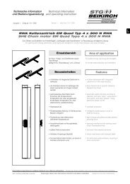
Technische Information Technical information<br />
und Bedienungsanleitung and operating instruction<br />
Ausgabe: 2 Gültig ab: 31.07.2006 Version: 2 valid from: 31.07.2006<br />
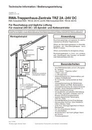
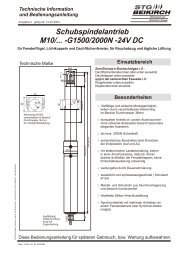
Abbildung: Netzteil NT 4A<br />
Illustration: Power pack NT 4A<br />
Datei:<br />
Ti_NT_4A_dt_engl.cdr<br />
Art.Nr. 24999981<br />
�<br />
�<br />
125<br />
24 V<br />
230 V<br />
90<br />
+24 +24 +24 - -<br />
�<br />
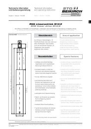
Netzteil NT 4A<br />
Power pack NT 4A<br />
Zum direkten Anschluss von 24 V Lüftungsantrieben bis max. 4 A<br />
To connect 24 V ventilation drives up to max. 4 A<br />
136<br />
Anwendung<br />
Das Netzteil NT 4A wird für die<br />
24-Volt-Gleichspannungsversorgung von<br />
Linear- und Kettenantrieben eingesetzt.<br />
Die Anzahl der anschließbaren Antriebe<br />
ergibt sich aus der Stromaufnahme der<br />
anzuschließenden Antriebe und dem<br />
Ausgangsstrom des Netzteils.<br />
Applications<br />
The power supply NT 4A is used for<br />
24 V DC power supply, for linear drives<br />
and chain motors.<br />
The number of window motors, which can<br />
be connected to the power supply unit<br />
depends on the power consumption of the<br />
respective window motors and the<br />
available output current of the power<br />
supply unit.<br />
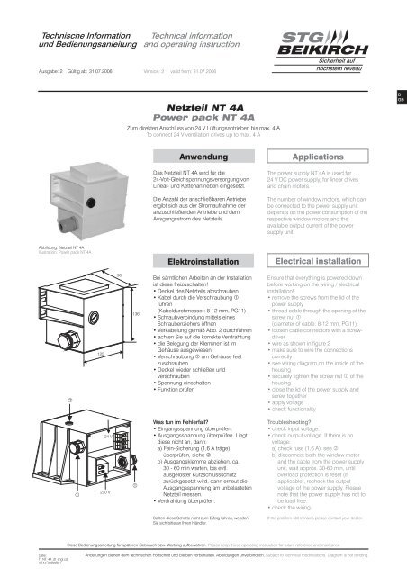
Elektroinstallation Electrical installation<br />
Bei sämtlichen Arbeiten an der Installation<br />
ist diese freizuschalten!<br />
Deckel des Netzteils abschrauben<br />
Kabel durch die Verschraubung �<br />
führen<br />
(Kabeldurchmesser: 8-12 mm, PG11)<br />
Schraubverbindung mittels eines<br />
Schraubenziehers öffnen<br />
Verkabelung gemäß Abb. 2 durchführen<br />
achten Sie auf die korrekte Verdrahtung<br />
die Belegung der Klemmen ist im<br />
Gehäuse ausgewiesen<br />
Verschraubung � am Gehäuse fest<br />
zuschrauben<br />
Deckel wieder schließen und<br />
verschrauben<br />
Spannung einschalten<br />
Funktion prüfen<br />
Was tun im Fehlerfall?<br />
Eingangsspannung überprüfen.<br />
Ausgangsspannung überprüfen. Liegt<br />
diese nicht an, dann:<br />
a) Fein-Sicherung (1,6 A träge)<br />
überprüfen, siehe �<br />
b) Ausgangsklemme abziehen, ca.<br />
30 - 60 min warten, bis evtl.<br />
ausgelöster Kurzschlussschutz<br />
zurückgesetzt wird, dann erneut die<br />
Ausgangsspannung am unbelasteten<br />
Netzteil messen.<br />
Verdrahtung überprüfen.<br />
Sollten diese Schritte nicht zum Erfolg führen, wenden<br />
Sie sich bitte an Ihren Händler.<br />
<strong>STG</strong><br />
BEIKIRCH<br />
Ensure that everything is powered down<br />
before working on the wiring / electrical<br />
installation!<br />
remove the screws from the lid of the<br />
power supply<br />
thread cable through the opening of the<br />
screw nut �<br />
(diameter of cable: 8-12 mm, PG11)<br />
loosen cable connectors with a screw-<br />
driver<br />
wire as shown in figure 2<br />
make sure to wire the connections<br />
correctly<br />
see wiring diagram on the inside of the<br />
housing<br />
securely tighten the screw nut � of the<br />
housing<br />
close the lid of the power supply and<br />
screw together<br />
apply voltage<br />
check functionality<br />
Sicherheit auf<br />
höchstem Niveau<br />
Troubleshooting?<br />
check input voltage.<br />
check output voltage. If there is no<br />
voltage:<br />
a) check fuse (1,6 A), see �<br />
b) disconnect both the window motor<br />
and the cable from the power supply<br />
unit, wait approx. 30-60 min, until<br />
overload protection is reset (if<br />
applicable), recheck the output<br />
voltage of the power supply. Please<br />
note that the power supply has not to<br />
be load free.<br />
check the wiring.<br />
If the problem still remains please contact your dealer.<br />
Diese Bedienungsanleitung für späteren Gebrauch bzw. Wartung aufbewahren. Please keep these operating instruction for future reference and maintance.<br />
Änderungen dienen dem technischen Fortschritt und bleiben vorbehalten. Abbildungen unverbindlich. Subject to technical modifications. Diagram is not binding.<br />
D<br />
GB
Sicherheitshinweise<br />
Sicherheitshinweise, die Sie unbedingt beachten müssen,<br />
werden durch besondere Zeichen hervorgehoben<br />
Vorsicht / Warnung / Achtung<br />
Gefahr für Personen durch elektrischen Strom<br />
Vorsicht / Warnung / Achtung<br />
Nichtbeachtung führt zur Zerstörung Gefährdung<br />
für Material durch falsche Handhabung<br />
Vorsicht / Achtung / Warnung<br />
Gefährdung für Personen durch Gefahren aus<br />
dem Gerätebetrieb. Quetsch- und Klemmgefahr<br />
INFO<br />
Warnung 230 V AC<br />
Gefährliche Spannung. Kann Tod, schwere Körperverletzung oder<br />
erheblichen Sachschaden verursachen. Trennen Sie das Gerät allpolig von<br />
der Versorgungsspannung bevor Sie es öffnen, montieren oder den Aufbau<br />
verändern. VDE 0100 für 230 V Netzanschluss beachten.<br />
Beachten Sie bei der Montage und Bedienung<br />
Das Fenster schließt automatisch. Beim Schließen und Öffnen stoppt der<br />
Antrieb über die Lastabschaltung. Die entsprechende Druckkraft entnehmen<br />
Sie bitte den technischen Daten. Die Druckkraft reicht aber auf jeden Fall aus<br />
bei Unachtsamkeit Finger zu zerquetschen.<br />
Bei der Montage und Bedienung nicht in den Fensterfalz und in den<br />
laufenden Antrieb greifen! Quetsch- und Klemmgefahr!<br />
Bedienungsanleitung<br />
für die fachgerechte Montage, Installation und angemessene Wartung durch<br />
den geschulten, sachkundigen und sicherheitsbewussten Elektro-Installateur<br />
und / oder Fachpersonal mit Kenntnissen der elektrischen Geräteinstallation.<br />
Lesen und Beachten Sie die Angaben in dieser Bedienungsanleitung und<br />
halten Sie die vorgegebene Reihenfolge ein. Diese Bedienungsanleitung für<br />
späteren Gebrauch / Wartung aufbewahren. Ein zuverlässiger Betrieb und<br />
ein Vermeiden von Schäden und Gefahren ist nur bei sorgfältiger Montage<br />
und Einstellung nach dieser Anleitung gegeben. Bitte beachten Sie genau<br />
die Anschlussbelegung, die minimalen und max. Leistungsdaten (siehe<br />
technischen Daten) und die Installationshinweise.<br />
Es würde den Rahmen dieser Bedienungsanleitung sprengen, alle gültigen<br />
Bestimmungen und Richtlinien aufzulisten. Prüfen Sie immer, ob Ihre Anlage<br />
den gültigen Bestimmungen entspricht. Besondere Beachtung finden dabei:<br />
Öffnungsquerschnitt des Fensters, Öffnungszeit und Öffnungsgeschwindigkeit,<br />
Temperaturbeständigkeit von Kabel und Geräten. Benötigtes Befestigungsmaterial<br />
ist mit dem Baukörper und der entsprechenden Belastung<br />
abzustimmen und, wenn nötig, zu ergänzen. Ein eventuell mitgeliefertes<br />
Befestigungsmaterial entspricht nur einem Teil der Erfordernisse.<br />
Leitungsverlegung und elektrischer Anschluss nur durch zugelassene<br />
Elektrofirma. Netzzuleitungen 230 V AC separat bauseits absichern.<br />
Netzzuleitungen bis an die Netzklemme ummantelt lassen. Bei der<br />
Installation DIN- und VDE-Vorschriften beachten, VDE 0100 Errichten von<br />
Starkstromanlagen bis 1000 V, VDE 0815 Installationskabel und -leitungen,<br />
VDE 0833 Gefahrenmelde-anlagen für Brand, Einbruch und Überfall.<br />
Kabeltypen ggf. mit den örtlichen Abnahmebehörden, Energieversorgungsunternehmen,<br />
Brandschutzbehörden oder Berufs-genossenschaften<br />
festlegen. Alle Niederspannungsleitungen (24 V DC) getrennt von Starkstromleitungen<br />
verlegen. Flexible Leitungen dürfen nicht eingeputzt werden.<br />
Frei hängende Leitungen mit Zugentlastung versehen. Die Leitungen<br />
müssen so verlegt sein, dass sie im Betrieb weder abgeschert, verdreht<br />
noch abgeknickt werden. Abzweigdosen müssen für Wartungsarbeiten<br />
zugänglich sein. Die Kabelarten, -längen und -querschnitte gemäß den<br />
technischen Angaben ausführen.<br />
Vor jeder Wartungsarbeit oder Veränderung des Aufbaus sind die<br />
Netzspannung und Akkus allpolig abzuklemmen. Gegen unbeabsichtigtes<br />
Wiedereinschalten ist die Anlage abzusichern. Elektrische Steuerungen<br />
müssen stromlos sein, bevor Sie Teile entnehmen oder dazusetzen<br />
(Netzspannung und Akkus abklemmen).<br />
Nach der Installation und jeder Veränderung der Anlage alle Funktionen<br />
durch Probelauf überprüfen.<br />
Achtung:<br />
Die Antriebe nur mit Steuerungen vom gleichen Hersteller<br />
betreiben. Bei Verwendung von Fremdfabrikaten keine Haftung, Garantieund<br />
Serviceleistungen. Die Montage und Installation muss sachgemäß,<br />
sicherheitsbewusst und nach Angaben der Bedienungsanleitung erfolgen.<br />
Werden Ersatzteile, Ausbauteile oder Erweiterungen benötigt bzw.<br />
gewünscht, ausschließlich Original-Ersatzteile verwenden.<br />
Herstellererklärung<br />
Die Geräte sind gemäß der europäischen Richtlinien geprüft und hergestellt.<br />
Eine entsprechende Herstellererklärung liegt vor. Sie dürfen die Geräte nur<br />
dann betreiben, wenn für das Gesamtsystem eine Konformitätserklärung<br />
vorliegt.<br />
2<br />
Please observe the following safety which are emphasized<br />
by special symbols<br />
Caution / Warning / Attention<br />
Danger to persons due to electricity<br />
Caution / Warning / Attention<br />
Non-observance leads to destruction<br />
Danger to material due to incorrect handling<br />
Caution / Attention / Warnng<br />
Danger to persons due to risks arising from the<br />
operation of the equipment. Danger of crushing/trapping<br />
INFO<br />
Safety instructions<br />
Warning 230 V AC<br />
Dangerous voltage. Can cause death, serious injury or considerable material<br />
damage. Disconnect the equipment from the power supply at all poles<br />
before opening, assembling or carrying out any structural alterations.<br />
Observe VDE 0100 for 230 V power connection.<br />
Please observe the following for assembly and operation<br />
The window closes automatically. When opening and closing, the drive unit<br />
is stopped by the power cut-off. The corresponding pressure force is listed in<br />
the technical data. Take care - the pressure force is high enough to crush<br />
your fingers.<br />
During assembly and operation, do not interfere with the window gap or the<br />
travelling drive! Danger of crushing/trapping!<br />
Operating instructions<br />
for professional assembly, installation and appropriate maintenance by<br />
trained, qualified and safety-conscious electricians and/or skilled staff with<br />
knowledge of electrical equipment installation. Read and observe the<br />
information contained in these operating instructions and respect the order<br />
of procedure stated therein. Please keep these operating instructions for<br />
future reference and maintenance. Reliable operation and the prevention of<br />
damage and risks are only granted if the equipment is assembled carefully<br />
and the settings are carried out according to these instructions. Please<br />
observe the exact terminal assignment, the minimum and maximum power<br />
ratings (see technical data) and the installation instructions.<br />
It would be beyond the scope of these safety instructions to list all the valide<br />
regulations and guidelines. Always make sure that your system corresponds<br />
to the valid regulations. Pay particular attention to: the aperture cross-section<br />
of the window, the opening time and opening speed, the temperature<br />
resistance of the cables and equipment, cross-sections of the cables in<br />
relation to the cable lengths and power consumption. Required mounting<br />
material is to be adapted to the frame and the corresponding load and is to<br />
be completed, if necessary. Any supplied mounting material is only part of<br />
the required amount.<br />
Routing of cables and electrical connections only to be done by a qualified<br />
electrician. Power supply leads 230 V AC to be fused separately by the<br />
customer. Keep power supply leads sheathed until the mains terminal.<br />
DIN and VDE regulations to be observed for the installation: VDE 0100<br />
Setting up of high voltage installations up to 1000 V. VDE 0815 Installation<br />
cables and wires. VDE 0833 Alarm systems for fire, break-in and burglary.<br />
Cable types to be agreed with local inspection authorities, power utilities, fire<br />
protection authority and the professional associations. All low voltage cables<br />
(24 V DC) to be installed separately from high voltage cables. Flexible cables<br />
must not be plastered in. Provide tension relief for freely suspended cables.<br />
The cables must be installed in such a way that they cannot be sheared off,<br />
twisted or bent off during operation. Junction boxes must be accessible for<br />
maintenance work. Adhere to the type of cables, cable lengths and crosssections<br />
as stated in the technical information.<br />
The supply voltage and the batteries are to be disconnected at all poles<br />
before maintenance work or structural alterations. The system must be<br />
protected against unintentional re-starting. Electrical controls must be<br />
voltage free before extension modules are taken off or added (disconnect<br />
mains voltage and batteries).<br />
After installation and any changes to the system check all functions by a trial<br />
run.<br />
Attention:<br />
The control must only be operated with drives made by the same<br />
manufacturer. No liability will be accepted and no guarantee nor service is<br />
granted if products of outside manufacturers are used. Assembly and<br />
installation must be carried out properly, according to the information of the<br />
operating instructions paying particular attention to safety aspects. If spare<br />
parts, dismantled parts or extension components are required or desired,<br />
only use original spare parts.<br />
Manufacturer’s declaration<br />
The equipment has been manufactured and tested according to the<br />
European regulations. A corresponding manufacturer’s declaration has been<br />
submitted. You may only operate the system if a Declaration of Conformity<br />
exists for the entire system.
Montage / Kabelverlegeplan Assembly / Routing of cables<br />
Die Montage des Netzteils muss im trockenen<br />
Raum erfolgen. Die Montageorte der<br />
Lüftungstaster müssen gut sichtbar und<br />
erreichbar sein. Nicht hinter Wandvorsprüngen,<br />
Türflügeln oder hinter Baukörpern verdeckt<br />
montieren.<br />
Löcher gemäß Abb. 1 in die Wand bohren<br />
Dübel in die Wand setzen, Netzteil<br />
anschrauben<br />
Elektroinstallation vornehmen<br />
M<br />
=<br />
braun<br />
brown<br />
Betriebsspannung<br />
Stromaufnahme<br />
Systemspannung<br />
Max. Stromabgabe<br />
Einschaltdauer<br />
Schutzart<br />
Umweltklasse<br />
Gehäuse<br />
blau<br />
blue<br />
Gehäuseabmessungen<br />
Umgebungstemperatur<br />
Motorsicherung<br />
Anschlussleitungen<br />
Max. Leitungslänge<br />
24 V DC Antrieb mit eingebauter Lastabschaltung oder Endschalter<br />
24 V DC motor drive with integrated power cut-off or end switch<br />
P AUF P<br />
ZU Open<br />
Closed<br />
Ö S Ö S<br />
Abzweigdose<br />
junction box<br />
Lüftungstaster<br />
LTA 11AP/UP<br />
vent switch<br />
LTA 11AP/UP<br />
230 V AC / 50 / 60 Hz (+ / -10 %)<br />
max. 0,73 A<br />
24 V DC (Nenn) (-10 %/+10 %)<br />
max. 4 A<br />
1 min EIN / 3 min AUS<br />
IP54 nach DIN 40050<br />
II<br />
Kunststoff schwarz,<br />
für Auf-Putz-Montage<br />
125x90x136mm(HxBxT)<br />
0-60°C<br />
1,6 AT<br />
+-<br />
Anschlussplan Antrieb, Abzeigdose, Lüftungstaster und Netzteil<br />
terminal diagram for motor drive, junction box, vent switch and power pack<br />
Versorgung<br />
24 V DC, max.<br />
Stromaufnahme<br />
der Antriebe<br />
beachten<br />
supply 24 V DC, max.<br />
current consumption<br />
of the drives consider<br />
Netzteil<br />
power pack<br />
Eingang /Netzleitung: 1x2x1,5mm<br />
2<br />
Ausgangsseite: 1 x 4 x 2,5 mm<br />
50 m zwischen Netzteil und Antrieb<br />
23,5 mm<br />
115 mm Abbildung 1: Bohrungen<br />
Illustration 1: Drill holes<br />
2<br />
weitere Antriebe<br />
additional motors<br />
Operating voltage<br />
Current consumption mains<br />
Voltage output<br />
Output current<br />
Intermitted operation<br />
Protection level<br />
Protection class<br />
Housing<br />
Dimensions<br />
Ambient temperature<br />
Motor fuse<br />
Connecting cable<br />
Abzweigdose<br />
junction box<br />
Max. length of cable<br />
The mounting position of the power pack must<br />
be in a dry room. The mounting position of the<br />
vent switch has to be visible and easy to<br />
approach. Do not mount behind wall recesses,<br />
door wings or other locations covered by parts<br />
of the building.<br />
Drill 4 holes into the wall as shown in<br />
illustrationfig. 1<br />
Insert plug in the wall, attach power supply<br />
proceed with electrical istallation<br />
Lüftungstaster:<br />
LTA11 AP/UP<br />
vent switch<br />
LTA11 AP/UP<br />
Verdrahtungsbeispiel Antriebe und Netzteil<br />
Example wiring for motor drive and power pack<br />
Technische Daten Technical data<br />
230 V AC / 50 / 60Hz (+ / -10 %)<br />
max. 0.73 A<br />
24<br />
max. 4 A<br />
1 min ON / 3 min OFF<br />
IP54 according to DIN 40050<br />
II<br />
V DC (nominal) (-10 % / +10 %)<br />
plastic black,<br />
for surface mounting<br />
125x90x136mm(hxwxd)<br />
0-60°C<br />
1.6 AT<br />
Antrieb<br />
motor<br />
Input / mains: 1 x 2 x 1.5 mm<br />
2<br />
Output: 1 x 4 x 2.5 mm<br />
50 m between power pack and<br />
motor<br />
L<br />
N<br />
Netzteil<br />
power pack<br />
230 V AC<br />
2<br />
3<br />
D<br />
GB