Ti_WRM_40M_4G_8G_ dt_engl.cdr - STG-Beikirch
Ti_WRM_40M_4G_8G_ dt_engl.cdr - STG-Beikirch
Ti_WRM_40M_4G_8G_ dt_engl.cdr - STG-Beikirch

Sie wollen auch ein ePaper? Erhöhen Sie die Reichweite Ihrer Titel.
YUMPU macht aus Druck-PDFs automatisch weboptimierte ePaper, die Google liebt.
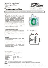
Technische Information Technical information<br />
und Bedienungsanleitung and operating instruction<br />
Ausgabe: 1 Gültig ab: 09.11.2006 Version: 1 valid from: 09.11.2006<br />
<strong>WRM</strong> <strong>40M</strong>-<strong>4G</strong><br />
<strong>WRM</strong> <strong>40M</strong>-<strong>8G</strong><br />
<strong>WRM</strong> <strong>40M</strong>-<strong>8G</strong><br />
Wind- und Regenmeldeanlage<br />
<strong>WRM</strong> <strong>40M</strong>-<strong>4G</strong> & <strong>WRM</strong> <strong>40M</strong>-<strong>8G</strong><br />
Wind and rain detection system<br />
<strong>WRM</strong> <strong>40M</strong>-<strong>4G</strong> and <strong>WRM</strong> <strong>40M</strong>-<strong>8G</strong><br />
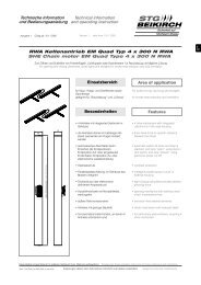
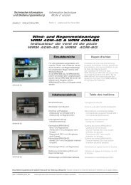
Einsatzbereiche Areas of use<br />
Für Lüftungszwecke ausgestattete<br />
Lichtkuppeln, Fenster und Lichtbänder<br />
werden durch die Wind- und<br />
Regenmeldeanlage bei einsetzendem<br />
Regen, Schnee oder Wind geschlossen.<br />
An die <strong>WRM</strong> <strong>40M</strong>-<strong>4G</strong> und <strong>WRM</strong> <strong>40M</strong>-<strong>8G</strong><br />
können 40 Antriebe (230 V)<br />
angeschlossen werden.<br />
Bei der <strong>WRM</strong> <strong>40M</strong>-<strong>4G</strong> können die<br />
Antriebe auf 4 Gruppen, bei der<br />
<strong>WRM</strong> <strong>40M</strong>-<strong>8G</strong> auf bis zu 8 Gruppen<br />
verteilt werden.<br />
Inhaltsverzeichnis Specification<br />
Sicherheitshinweise<br />
Windstärken nach Beaufort<br />
Anschluss und Kabelplan<br />
Ansteuerung von Antrieben 230 V<br />
Ansteuerung von Magnetventilen<br />
Leistungsbeschreibung<br />
Installationsanleitung<br />
Klemmpläne <strong>WRM</strong> <strong>40M</strong>-<strong>4G</strong><br />
Wind-/ und Regensensor<br />
Antrieb 230 V mit Lüftungstaster<br />
(eine Gruppe)<br />
Magnetventil 230 V mit Lüftungstaster<br />
(eine Gruppe)<br />
Klemmpläne <strong>WRM</strong> <strong>40M</strong>-<strong>8G</strong><br />
Antrieb 230 V mit Lüftungstaster<br />
(mehrere Gruppen)<br />
Abmessungen Wind/- und Regensensor<br />
Bedienung und Einstellung Wind / und<br />
Regenmeldeanlage<br />
Abmessungen<br />
<strong>STG</strong><br />
BEIKIRCH<br />
Dome lights, windows and rows of roof<br />
lights equipped for ventilation purposes<br />
are connected with the wind and rain<br />
detection system in the event of rain, snow<br />
or wind.<br />
40 (230 V) drives can be connected to the<br />
<strong>WRM</strong> <strong>40M</strong>-<strong>4G</strong> and <strong>WRM</strong> <strong>40M</strong>-<strong>8G</strong>.<br />
In the case of <strong>WRM</strong> <strong>40M</strong>-<strong>4G</strong> the motors<br />
can be distributed over 4 groups, in the<br />
case of <strong>WRM</strong> <strong>40M</strong>-<strong>8G</strong> up to 8 groups.<br />
Safety instructions<br />
Wind forces as per beaufort<br />
Connection and cable plan<br />
Control of drives 230 V<br />
Contol of solenoid valves<br />
Specification<br />
Installation Instructions<br />
Terminal plans <strong>WRM</strong> <strong>40M</strong>-<strong>4G</strong><br />
Wind / and rain sensor<br />
230 V drive with ventilation pushbutton<br />
unit (one group)<br />
Solenoid valve 230 V with ventilation<br />
pushbutton unit (un groupe)<br />
Terminal plans <strong>WRM</strong> <strong>40M</strong>-<strong>8G</strong><br />
230 V drive with ventilation pushbutton<br />
unit (several groups)<br />
Dimensions wind / and rain sensor<br />
Operating and setting wind / and rain<br />
direction system<br />
Dimensions<br />
Sicherheit auf<br />
höchstem Niveau<br />
Diese Bedienungsanleitung für späteren Gebrauch bzw. Wartung aufbewahren. Please keep these operating instruction for future reference and maintance.<br />
Datei:<br />
Änderungen dienen dem technischen Fortschritt und bleiben vorbehalten. Abbildungen unverbindlich. Subject to technical modifications. Diagram is not binding.<br />
<strong>Ti</strong>_<strong>WRM</strong>_<strong>40M</strong>_<strong>4G</strong>_<strong>8G</strong>_<strong>dt</strong>_<strong>engl</strong>.<strong>cdr</strong><br />
Art.Nr. 24999627<br />
D<br />
GB
Sicherheitshinweise<br />
Sicherheitshinweise, die Sie unbedingt beachten müssen,<br />
werden durch besondere Zeichen hervorgehoben<br />
Vorsicht / Warnung / Achtung<br />
Gefahr für Personen durch elektrischen Strom<br />
Vorsicht / Warnung / Achtung<br />
Nichtbeachtung führt zur Zerstörung Gefährdung<br />
für Material durch falsche Handhabung<br />
Vorsicht / Achtung / Warnung<br />
Gefährdung für Personen durch Gefahren aus<br />
dem Gerätebetrieb Quetsch- und Klemmgefahr<br />
INFO<br />
Warnung 230 V AC<br />
Gefährliche Spannung. Kann Tod, schwere Körperverletzung oder<br />
erheblichen Sachschaden verursachen. Trennen Sie das Gerät<br />
allpolig von der Versorgungsspannung bevor Sie es öffnen,<br />
montieren oder den Aufbau verändern. VDE 0100 für 230 V<br />
Netzanschluss beachten.<br />
Beachten Sie bei der Montage und Bedienung<br />
Das Fenster schließt automatisch.<br />
Beim Schließen und Öffnen stoppt der Antrieb über die<br />
Lastabschaltung. Die entsprechende Druckkraft entnehmen Sie<br />
bitte den technischen Daten. Die Druckkraft reicht aber auf jeden<br />
Fall aus bei Unachtsamkeit Finger zu zerquetschen.<br />
Bei der Montage und Bedienung nicht in den Fensterfalz und in<br />
den laufenden Antrieb greifen!<br />
Quetsch- und Klemmgefahr!<br />
Bedienungsanleitung<br />
für die fachgerechte Montage, Installation und angemessene<br />
Wartung durch den geschulten, sachkundigen und<br />
sicherheitsbewussten Elektro-Installateur und / oder Fachpersonal<br />
mit Kenntnissen der elektrischen Geräteinstallation.<br />
Lesen und Beachten Sie die Angaben in dieser<br />
Bedienungsanleitung und halten Sie die vorgegebene Reihenfolge<br />
ein.<br />
Diese Bedienungsanleitung für späteren Gebrauch / Wartung<br />
aufbewahren. Ein zuverlässiger Betrieb und ein Vermeiden von<br />
Schäden und Gefahren ist nur bei sorgfältiger Montage und<br />
Einstellung nach dieser Anleitung gegeben.<br />
Bitte beachten Sie genau die Anschlussbelegung, die minimalen<br />
und maximalen Leistungsdaten (siehe technischen Daten) und die<br />
Installationshinweise.<br />
Es würde den Rahmen dieser Bedienungsanleitung sprengen, alle<br />
gültigen Bestimmungen und Richtlinien aufzulisten.<br />
Prüfen Sie immer, ob Ihre Anlage den gültigen Bestimmungen<br />
entspricht. Besondere Beachtung finden dabei:<br />
Öffnungsquerschnitt des Fensters, Öffnungszeit und<br />
Öffnungsgeschwindigkeit, Temperaturbeständigkeit von Kabel und<br />
Geräten, Querschnitte der Kabel in Abhängigkeit von<br />
Leitungslängen und Stromaufnahme.<br />
Leitungsverlegung und elektrischer Anschluss nur durch<br />
zugelassene Elektrofirma.<br />
Bei der Installation DIN- und VDE-Vorschriften beachten, VDE 0815<br />
Installationskabel und -leitungen. VDE 0833 Gefahrenmeldeanlagen<br />
für Brand, Einbruch und Überfall.<br />
Kabeltypen ggf. mit den örtlichen Abnahmebehörden, Energieversorgungsunternehmen,<br />
Brandschutzbehörden oder Berufsgenossenschaften<br />
festlegen.<br />
Alle Niederspannungsleitungen (24 V DC) getrennt von<br />
Starkstromleitungen verlegen. Flexible Leitungen dürfen nicht<br />
eingeputzt werden. Frei hängende Leitungen mit Zugentlastung<br />
versehen. Die Leitungen müssen so verlegt sein, dass sie im<br />
Betrieb weder abgeschert, verdreht noch abgeknickt werden.<br />
Abzweigdosen müssen für Wartungsarbeiten zugänglich sein.<br />
Die Kabelarten, -längen und -querschnitte gemäß den technischen<br />
Angaben ausführen.<br />
2<br />
Caution / Warning / Attention<br />
Danger to persons due to electricity<br />
Caution / Warning / Attention<br />
Non-observance leads to destruction<br />
Danger to material due to incorrect handling<br />
Caution / Attention / Warning<br />
Danger to persons due to risks arising from the<br />
operation of the equipment. Danger of crushing/trapping<br />
INFO<br />
Safety instructions<br />
Please observe the following safety which are emphasized<br />
by special symbols<br />
Warning 230 V AC<br />
Dangerous voltage. Can cause death, serious injury or considerable<br />
material damage. Disconnect the equipment from the power supply<br />
at all poles before opening, assembling or carrying out any structural<br />
alterations. Observe VDE 0100 for 230 V power connection.<br />
Please observe the following for assembly and operation<br />
The window closes automatically.<br />
When opening and closing, the drive unit is stopped by the power<br />
cut-off. The corresponding pressure force is listed in the technical<br />
data. Take care - the pressure force is high enough to crush your<br />
fingers.<br />
During assembly and operation, do not interfere with the window gap<br />
or the travelling drive!<br />
Danger of crushing/trapping!<br />
Operating instructions<br />
for professional assembly, installation and appropriate maintenance<br />
by trained, qualified and safety-conscious electricians and/or skilled<br />
staff with knowledge of electrical equipment installation.<br />
Read and observe the information contained in these operating<br />
instructions and respect the order of procedure stated therein.<br />
Please keep these operating instructions for future reference and<br />
maintenance. Reliable operation and the prevention of damage and<br />
risks are only granted if the equipment is assembled carefully and the<br />
settings are carried out according to these instructions and to the<br />
operating instructions of the drives.<br />
Please observe the exact terminal assignment, the minimum and<br />
maximum power ratings (see technical data) and the installation<br />
instructions.<br />
It would be beyond the scope of these safety instructions to list all the<br />
valide regulations and guidelines.<br />
Always make sure that your system corresponds to the valid<br />
regulations. Pay particular attention to: the aperture cross-section of<br />
the window, the opening time and opening speed, the temperature<br />
resistance of the cables and equipment, cross-sections of the cables<br />
in relation to the cable lengths and power consumption. Required<br />
mounting material is to be adapted to the frame and the<br />
corresponding load and is to be completed, if necessary. Any<br />
supplied mounting material is only part of the required amount.<br />
Routing of cables and electrical connections only to be done by a<br />
qualified electrician.<br />
DIN and VDE regulations to be observed for the installation: VDE<br />
0100 Setting up of high voltage installations up to 1000 V. VDE 0815<br />
Installation cables and wires. VDE 0833 Alarm systems for fire, breakin<br />
and burglary.<br />
Cable types to be agreed with local inspection authorities, power<br />
utilities, fire protection authority and the professional associations.<br />
All low voltage cables (24 V DC) to be installed separately from high<br />
voltage cables. Flexible cables must not be plastered in. Provide<br />
tension relief for freely suspended cables. The cables must be<br />
installed in such a way that they cannot be sheared off, twisted or<br />
bent off during operation. Junction boxes must be accessible for<br />
maintenance work. Adhere to the type of cables, cable lengths and<br />
cross-sections as stated in the technical information.
Sicherheitshinweise Safety instructions<br />
Vor jeder Wartungsarbeit oder Veränderung des Aufbaus<br />
ist die Netzspannung allpolig abzuklemmen. Gegen<br />
unbeabsichtigtes Wiedereinschalten ist die Anlage<br />
abzusichern.<br />
Elektrische Steuerungen müssen stromlos sein, bevor Sie Teile<br />
entnehmen oder dazusetzen (Netzspannung abklemmen).<br />
Nach der Installation und jeder Veränderung der Anlage alle<br />
Funktionen durch Probelauf überprüfen.<br />
Beachten Sie bei der Montage und Bedienung: die Fenster<br />
schließen automatisch!<br />
Quetsch- und Scherstellen zwischen Fensterflügel und Rahmen,<br />
Lichtkuppeln und Aufsetzkranz müssen bis zu einer Höhe von<br />
2,5 m durch Einrichtungen gesichert sein, die bei Berührung oder<br />
Unterbrechung durch eine Person, die Bewegung zum Stillstand<br />
bringen (Richtlinie für kraftbetätigte Fenster, Türen und Tore der<br />
Berufsgenossenschaft).<br />
Achtung:<br />
Steuerungen und externe Geräte vom gleichen<br />
Hersteller auswählen. Bei Verwendung von Fremdfabrikaten<br />
können Abweichungen der Leistungsdaten<br />
auftreten. Werden Ersatzteile, Ausbauteile oder<br />
Erweiterungen benötigt bzw. gewünscht ausschließlich<br />
Original-Ersatzteile verwenden.<br />
Herstellererklärung<br />
Die Geräte sind gemäß der europäischen Richtlinien geprüft und<br />
hergestellt. Eine entsprechende Herstellererklärung liegt vor. Sie<br />
dürfen die Geräte nur dann betreiben, wenn für das Gesamtsystem<br />
eine Konformitätserklärung vorliegt.<br />
Windstärken nach Beaufort<br />
Windstärke Merkmal Geschwindigkeit m/s km/h<br />
Staudruck*<br />
nach Beaufort characteristic speed m/s k m/h<br />
Pa = N/m²<br />
wind forces dynamic pressure*<br />
as per beaufort<br />
Pa = N/m²<br />
0 Stille / calm<br />
0 - 0,2 unter 1<br />
less than 1<br />
0 - 0,2<br />
1 leiser Zug / light air<br />
0,3 - 1,5 1 - 5 0,06 - 1,4<br />
2 leichte Brise / light breeze<br />
1,6 - 3,3 6 - 11 1,6 - 6,8<br />
3 schwache Brise / gentle breeze 3,4 - 5,4 12 - 19 7,2 - 18,2<br />
4 mäßige Brise / moderate breeze 5,5 - 7,9 20 - 28 18,9 - 39.0<br />
5 frische Brise / fresh breeze<br />
8,0 - 10,7 29 - 38 40 - 71,6<br />
6 starke Brise / strong breeze<br />
10,8 - 13,8 39 - 49 72,9 - 119,0<br />
7 steifer Wind / near gale<br />
13,9 - 17,1 50 - 61 120,8 - 182,8<br />
8 stürmischer Wind / gale<br />
17,2 - 20,7 62 - 74 184,9 - 267,8<br />
9 Sturm / severe gale<br />
20,8 - 24,4 75 - 88 270,4 - 372,1<br />
10 schwerer Sturm / storm<br />
24,5 - 28,4 89 - 102 375,2 - 504,1<br />
11 orkarnartiger Sturm / violent storm 28,5 - 32,6 103 - 117 507,7 - 664,2<br />
12 Orkan / hurricane<br />
32,7 u. mehr 118 u. mehr<br />
668,3 u. mehr<br />
32.7 and more 118 and more 668.3 and more<br />
* Die Staudruck-Angaben wurden vereinfacht berechnet<br />
(P = Staudruck, V in m/s) P = V²/1,6 (Pa = N/m²)<br />
The supply voltage and the batteries are to be<br />
disconnected at all poles before maintenance work or<br />
structural alterations. The system must be protected<br />
against unintentional re-starting. Electrical controls must<br />
be voltage free before extension modules are taken off or<br />
added (disconnect mains voltage and batteries).<br />
After installation and any changes to the system check all functions<br />
by a trial run.<br />
During assembly and operation, please observe: the windows may<br />
close automatically.<br />
Potential crushing and cutting points between the casement and<br />
the window frame, dome lights and support frame must be secured<br />
up to a height of 2.5 m by safety equipment, which if touched or<br />
interrupted by a person will immediately stop the movement<br />
(guideline for power operated windows, doors and gates of the<br />
professional association).<br />
Attention:<br />
The control must only be operated with drives<br />
made by the same manufacturer. No liability will be<br />
accepted and no guarantee nor service is granted if<br />
products of outside manufacturers are used. Assembly<br />
and installation must be carried out properly, according<br />
to the information of the operating instructions paying<br />
particular attention to safety aspects. If spare parts,<br />
dismantled parts or extension components are required<br />
or desired, only use original spare parts.<br />
Manufacturer’s declaration<br />
The equipment has been manufactured and tested according to<br />
the European regulations. A corresponding manufacturer’s<br />
declaration has been submitted. You may only operate the system if<br />
a Declaration of Conformity exists for the entire system.<br />
Wind forces as per beaufort<br />
* The dynamic pressure details have been calculated in a simplified manner<br />
(P = dynamic pressure, V in m/s) P = V²/1.6 (Pa = N/m²)<br />
3<br />
D<br />
GB
4<br />
5<br />
9<br />
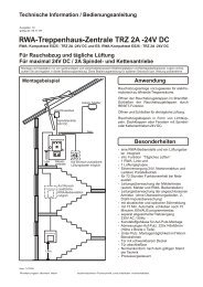
Anschluss und Kabelplan<br />
Ansteuerung von Antrieben 230 V<br />
9<br />
5<br />
3<br />
3<br />
Ansteuerung von Magnetventilen<br />
8<br />
2<br />
2<br />
8<br />
7<br />
AUF<br />
OPEN<br />
11<br />
7<br />
4<br />
4<br />
ZU<br />
CLOSED<br />
Lüftung<br />
Ventilation<br />
AUF ZU<br />
OPEN CLOSED<br />
Lüftung<br />
Ventilation<br />
7<br />
7<br />
6<br />
6<br />
1<br />
1<br />
10<br />
Connection and cable plan<br />
Control of drives 230 V<br />
1<br />
2<br />
3<br />
4<br />
5<br />
6<br />
7<br />
8<br />
9<br />
1<br />
2<br />
3<br />
4<br />
5<br />
7<br />
8<br />
9<br />
10<br />
11<br />
Aufsetzkranz mit Lichtkuppel<br />
frame with dome light<br />
Antrieb 230 V<br />
drive 230 V<br />
Wind- und Regensensor mit Standrohr<br />
wind and rain sensor with standpipe<br />
Verteilerdose (bauseits)<br />
distribution box (customer-supplied)<br />
Wind- und Regenmeldeanlage (Zentrale)<br />
wind and rain detection system (central control unit)<br />
230 V Lüftungstaster (keine Schalter verwenden)<br />
230 V ventilation pushbutton unit<br />
(do not use switches)<br />
NYM-I 4 x 1.5 mm²<br />
NYM-I 4 x 1.5 mm²<br />
I-Y(ST)Y 4x2x0,8Leitungslängen bis 150 m<br />
I-Y(ST)Y 6x2x0,8Leitungslängen bis 300 m<br />
(Adern doppelt auflegen)<br />
I-Y(ST)Y 4x2x0.8line lengths up to 150 m<br />
I-Y(ST)Y 6x2x0.8line lengths up to 300 m<br />
(lay duplicate wiring)<br />
Netzzuleitung 230 V/50/60Hzmax. 16 A<br />
mains cable 230 V/50/60Hzmax. 16 A<br />
Control of solenoid valves<br />
Aufsetzkranz mit Lichtkuppel<br />
surface crown with dome light<br />
Antrieb 230 V (pneumatischer Zylinder)<br />
drive 230 V (pneumatic cylinder)<br />
Wind- und Regensensor mit Standrohr<br />
wind and rain sensor with standpipe<br />
Verteilerdose (bauseits)<br />
distribution box (customer-supplied)<br />
Wind- und Regenmeldeanlage (Zentrale)<br />
wind and rain detection system (central control unit)<br />
6 230 V Lüftungstaster (keine Schalter verwenden)<br />
230 V ventilation pushbutton unit<br />
(do not use switches)<br />
NYM-I 4 x 1.5 mm²<br />
NYM-I 4 x 1.5 mm²<br />
I-Y(ST)Y 4x2x0,8Leitungslängen bis 150 m<br />
I-Y(ST)Y 6x2x0,8Leitungslängen bis 300 m<br />
(Adern doppelt auflegen)<br />
I-Y(ST)Y 4x2x0.8line lengths up to 150 m<br />
I-Y(ST)Y 6x2x0.8line lengths up to 300 m<br />
(lay duplicate wiring)<br />
Netzzuleitung 230 V/50/60Hzmax. 16 A<br />
mains cable 230 V/50/60Hzmax. 16 A<br />
Bauseitige Druckluftversorgung<br />
customer-supplied compressed air supply<br />
Magnetventil<br />
solenoid
Leistungsbeschreibung<br />
Für Lüftungszwecke ausgestattete Lichtkuppeln und Lichtbänder<br />
werden durch die Wind- und Regenmeldeanlage bei einsetzendem<br />
Regen, Schneefall oder Wind geschlossen.<br />
An die Wind- und Regenmeldeanlage <strong>WRM</strong> <strong>40M</strong>-<strong>4G</strong> und die <strong>WRM</strong><br />
40m-<strong>8G</strong> können 40 Antriebe 230 V angeschlossen werden. Bei der<br />
<strong>WRM</strong> <strong>40M</strong>-<strong>4G</strong> können die Motoren auf 4 Gruppen, bei der <strong>WRM</strong><br />
<strong>40M</strong>-<strong>8G</strong> auf bis zu 8 Gruppen verteilt werden.<br />
Es ist zu beachten, dass nicht mehr als 10 Antriebe in einer<br />
Gruppe angeschlossen werden. Die maximale Belastung pro<br />
Gruppe beträgt 6 A.<br />
Die Versorgung mit Netzspannung der einzelnen Gruppen erfolgt<br />
über die Wind- und Regenmeldeanlage. Soll eine Gruppe zur<br />
Ansteuerung einer 24 V RWA-Zentrale oder als potentialfreier<br />
Kontakt ausgeführt werden, so ist die Phase am Schütz in der<br />
jeweiligen Gruppe abzuklemmen, um die Niederspannungsanlage<br />
nicht zu zerstören.<br />
Über den Knebelschalter in der Abdeckhaube der Zentrale sind die<br />
jeweiligen Betriebsarten zu wählen. In der Schalterstellung<br />
“Automatik” werden alle Ausgänge bei Wind oder Regen<br />
geschaltet. Die Schalterstellung “Hand” setzt die Wind- und<br />
Regenmeldeanlage außer Betrieb. Bei einsetzendem Wind oder<br />
Regen würden die Lüftungsklappen oder Fenster nicht<br />
geschlossen werden. Mit der Schalterstellung “ZU” werden alle<br />
angeschlossenen Öffneraggregate durch die Wind- und Regenmeldeanlage<br />
geschlossen und sind nur nach Umschalten der<br />
Zentrale in die Betriebsart “Hand” bzw. “Automatik” über die<br />
Lüftertaster zu öffnen.<br />
In der Zentrale kann über je ein Potentiometer die Einschaltverzögerung<br />
und die Schaltschwelle für die Windgeschwindigkeit<br />
eingestellt werden.<br />
Vier Leuchtdioden informieren in der Zentrale über die Funktionen der<br />
Anlage.<br />
Optional kann ein zweiter Regensensor an die Wind- und<br />
Regenmeldeanlage angeschlossen werden.<br />
Bestan<strong>dt</strong>eile der Gesamtanlage<br />
- Zentrale im AP-Gehäuse und mit durchsichtiger Frontplatte<br />
- Wind- und Regensensor mit Befestigungswinkel (optional)<br />
- Korrosionsbeständiges Spezialstandrohr für die Montage auf<br />
Installationsanleitung<br />
Bringen Sie die Zentrale mit für den Untergrund geeigneten<br />
Schrauben und Dübeln an einem zweckmäßigen Ort an.<br />
Den Wind- und Regensensor mittels Standrohr auf der Dachfläche<br />
aufstellen und standsicher befestigen.<br />
Den Standort möglichst in der Mitte der Dachfläche wählen, um<br />
Verwirbelungen und Böen an der Dachkante zu meiden.<br />
Verdrahten Sie die gesamte Anlage nach dem Klemmplan auf den<br />
Seiten 6-7. Es ist unbedingt zu beachten, dass die<br />
Steuerleitungen des Wind- und Regensensors 24 V DC führen und<br />
diese Leitungen nicht zusammen mit Starkstromleitungen verlegt<br />
werden dürfen. Weiterhin sind die maximalen Kabellängen und<br />
Mindestquerschnitte gemäß den Vorgaben in der Anleitung<br />
auszuführen.<br />
Der Anschluss der Antriebe bzw. Magnetventile hat gemäß<br />
Klemmplan zu erfolgen. Beachten Sie, dass Arbeiten an<br />
netzspannungführenden Bauteilen und Anlagenteilen nur durch<br />
eine Elektrofachkraft durchgeführt werden dürfen und dass die<br />
Stromaufnahme aller 4 Gruppen nicht über 16 A liegen darf.<br />
Nach der kompletten Installation schließen Sie die Netzspannung an<br />
und überprüfen alle Funktionen und Betriebsarten der Anlage.<br />
Specification<br />
Dome lights, windows and rows of roof lights equipped for<br />
ventilation purposes are connected with the wind and rain<br />
detection system in the event of rain, snowfall or wind.<br />
40 drives types with 230 V can be connected to the wind and rain<br />
detection systems <strong>WRM</strong> <strong>40M</strong> - <strong>4G</strong> and <strong>WRM</strong> <strong>40M</strong> -<br />
8 G. In the case of <strong>WRM</strong> <strong>40M</strong> - <strong>4G</strong> the motors can be distributed<br />
over 4 groups, in the case of <strong>WRM</strong> <strong>40M</strong> - <strong>8G</strong> up to 8 groups can<br />
be distributed.<br />
Care is to be taken that no more than 10 motors of the above<br />
mentioned types can be connected per group. When connecting<br />
other drives it is to be taken into consideration that each group can<br />
be loaded with a maximum 6 A.<br />
The supply of mains power to the individual groups is provided by<br />
the wind and rain detection system. If one group is configured for<br />
control purposes as a 24 V SHE central control unit or as a<br />
potential-free contact, then the phase at the contactor of the group<br />
in question is to be disconnected in order not to destroy the low<br />
voltage system.<br />
The respective operating modes are to be selected using the<br />
toggle switch in the central control unit cover. All outputs are<br />
switched in the event of wind and rain in the “Automatic“ switch<br />
setting. The “Manual” switch setting puts the wind and rain<br />
detection system out of operation. The ventilation flaps are not<br />
closed when wind or rain starts. All opening units connected are<br />
closed by the wind and rain detection system using the switch<br />
position “Close“ and can only be opened using the ventilation<br />
pushbutton unit after switching over the central control unit in the<br />
operating mode “Manual“ or “Automatic“.<br />
The switch on delay and the switching threshold are set for the<br />
wind speed, each using a potentiometer in the central control unit.<br />
Four LEDs show the system functions in the central control unit.<br />
A second rain sensor can be connected to the wind and rain<br />
detection system as an option.<br />
Components of the total system<br />
- Central control unit in the surface-mounted housing with<br />
transparent front plate<br />
- Wind and rain sensor with angle bracket<br />
- Corrosion resistant special standpipe for fitting on the roof<br />
Installation Instructions<br />
Install the central control unit in a suitable location with screws and<br />
rawl plugs fit for the base surface.<br />
Place the wind and rain sensor on the roof surface using the<br />
standpipe and fasten securely.<br />
Select the location as near to the centre of the roof surface as<br />
possible, in order to avoid turbulence and gusts at the edge of the<br />
roof.<br />
Wire the whole of the system in accordance with the terminal plan<br />
on pages 6-7.Itisvital to take into account that the control lines<br />
for the wind and rain sensor carry 24 V DC and that these lines<br />
must not be laid together with high tension lines. Further the<br />
maximum cable lengths and minimum cross sections are to be<br />
designed in accordance with the parameters in the instructions.<br />
The drives or solenoid valves are to be connected in accordance<br />
with the terminal plan. Please note that work on components or<br />
parts of the system that carry mains voltage may only be carried<br />
out by an electrician and that the power consumption of all 4<br />
groups must not be exceed 16 A.<br />
After completing installation connect the supply voltage and check<br />
all system functions and operating modes.<br />
5<br />
D<br />
GB
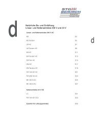
Klemmpläne <strong>WRM</strong> <strong>40M</strong>-<strong>4G</strong><br />
Wind-/ und Regensensor<br />
Achtung!<br />
Alle Leitungen zum Wind- und Regensensor führen 24 V<br />
und dürfen nicht mit Starkstromleitungen zusammen<br />
verlegt werden.<br />
Netzeinspeisung 230 V/50/60Hzmax. 16 A<br />
network power supply 230 V/50/60Hzmax. 16 A<br />
L<br />
N<br />
PE<br />
L N<br />
I-Y(ST)Y 4x2x0,8Leitungslängen bis 150 m<br />
l-Y(ST)Y 6x2x0,8Leitungslängen bis 300 m<br />
(Adern doppelt auflegen)<br />
I-Y(ST)Y 4x2x0.8line lengths up to 150 m<br />
I-Y(ST)Y 6x2x0.8line lengths up to 300 m<br />
(lay duplicate wiring)<br />
6<br />
L<br />
N<br />
PE<br />
blau zu N<br />
blue to N<br />
schwarz / black<br />
S A OE 1 2 3 4 5 6 7 8 PE 9 10 11 12 13<br />
br zu 1 und ZU<br />
brown to 1 and CLOSE<br />
1 2 3 7<br />
L1 L1 L1 L1 N 1 1 2 2 3 3 4 4 N<br />
M<br />
Antrieb (max. 10 Motoren je Gruppe)<br />
drive (max. 10 motors per group)<br />
Wind- und Regensensor<br />
wind and rain sensor<br />
<strong>WRM</strong> <strong>40M</strong>-<strong>4G</strong><br />
Antrieb mit Lüftungstaster (eine Gruppe)<br />
Netzeinspeisung 230 V/50/60Hzmax. 16 A<br />
Network power supply 230 V/50/60Hzmax. 16 A<br />
(L) Conductor<br />
(N) Neutral<br />
(PE) PE conductor<br />
weiß / white<br />
weiß / white<br />
grün gelb zu PE<br />
green yellow to PE<br />
Achtung!<br />
Pro Gruppe dürfen max. 10 Antriebe angeschlossen werden.<br />
Caution!<br />
A maximum of 10 drives may be connected per group.<br />
Terminal plans <strong>WRM</strong> <strong>40M</strong>-<strong>4G</strong><br />
Wind / and rain sensor<br />
8 1 2 3<br />
Caution!<br />
All lines for the wind and rain sensor carry 24 V and<br />
must not be laid together with high tension lines.<br />
Regensensor<br />
rain sensor<br />
N N N PEPE PE PE<br />
Auf Zu<br />
Open Close<br />
Lüftungstaster<br />
ventilation pushbutton unit<br />
Klemmleiste <strong>WRM</strong><br />
strip terminal <strong>WRM</strong><br />
I-Y(ST)Y 2x2x0,8Leitungslängen<br />
bis 150 m<br />
l-Y(ST)Y 4x2x0,8Leitungslängen<br />
bis 300 m<br />
(Adern doppelt auflegen)<br />
I-Y(ST)Y 2x2x0.8line lengths up<br />
to 150 m<br />
I-Y(ST)Y 4x2x0.8line lengths up<br />
to 300 m (lay duplicate wiring)<br />
Anschlussmöglichkeit für potentialfreien<br />
Schließer<br />
possible connection for potential-free<br />
closing contact<br />
<strong>WRM</strong> <strong>40M</strong>-<strong>4G</strong> drive with ventilation<br />
pushbutton unit (one group)<br />
Klemmleiste <strong>WRM</strong><br />
strip terminal <strong>WRM</strong><br />
NYM-I 4 x 1,5 mm²<br />
(NYM-I 6 x 1,5 mm² mit Kontroll-Leuchte)<br />
NYM-I 4 x 1.5 mm²<br />
(NYM-I 6 x 1.5 mm² with indicator light)<br />
Abzweigdose (bauseits)<br />
junction box (customer-supplied)
Magnetventil 230 V mit Lüftungstaster<br />
(eine Gruppe)<br />
Netzeinspeisung 230 V/50/60Hzmax. 16 A<br />
network power supply 230 V/50/60Hzmax. 16 A<br />
L<br />
N<br />
PE<br />
2<br />
4<br />
1. Antrieb<br />
first motor<br />
L<br />
N<br />
PE<br />
L1 L1 L1 L1 N 1 1 2 2 3 3 4 4 N<br />
<strong>WRM</strong> <strong>40M</strong>-<strong>8G</strong><br />
Antrieb mit Lüftungstaster (mehrere Gruppen)<br />
Netzeinspeisung 230 V/50/60Hzmax. 16 A<br />
network power supply 230 V/50/60Hzmax. 16 A<br />
M<br />
NYM 4 x 1,5 mm²<br />
NYM 4 x 1.5 mm²<br />
3<br />
Abzweigdose<br />
junction box<br />
Auf Zu<br />
Open Close<br />
Lüftungstaster<br />
ventilation pushbutton unit<br />
Solenoid valve 230 V with ventilation<br />
pushbutton unit (one groupe)<br />
Auf Zu<br />
Open Close<br />
N N N PEPE PE PE<br />
M<br />
M<br />
3<br />
4<br />
1<br />
1<br />
2<br />
3<br />
Lüftungstaster<br />
ventilation pushbutton unit<br />
Magnetventil 230 V<br />
solenoid valve 230V<br />
NYM-I 4 x 1,5 mm²<br />
NYM-I 4 x 1.5 mm²<br />
4 Abzweigdose (bauseits)<br />
junction box (customer-supplied)<br />
<strong>WRM</strong> <strong>40M</strong>-<strong>8G</strong> drive with ventilation<br />
pushbutton unit (several groups)<br />
L1 L1 L1 L1 N 1 1 2 2 3 3 4 4 5 5 6 6 7 7 8 8 N N N N N N N N PE PE PEPEPEPEPEPE weiß white weiß white<br />
weiß white<br />
braun zu 1 und ZU<br />
brown to 1 and<br />
CLOSE<br />
blau zu N<br />
blue to N<br />
schwarz black<br />
weiterer Antrieb<br />
further motor<br />
grün gelb zu PE<br />
green yellow to PE<br />
weiterer Antrieb<br />
further motor<br />
weiß white<br />
braun zu 8 und ZU<br />
brown to 8 and Close<br />
blau zu N<br />
blue to N<br />
schwarz black<br />
weiß white<br />
weiß white<br />
braun zu 8 und ZU<br />
brown to 8 and Close<br />
blau zu N<br />
blue to N<br />
schwarz black<br />
Klemmleiste <strong>WRM</strong><br />
strip terminal <strong>WRM</strong><br />
Abzweigdose<br />
junction box<br />
Klemmleiste <strong>WRM</strong><br />
strip terminal <strong>WRM</strong><br />
Auf Zu<br />
Open Close<br />
Lüftungstaster<br />
ventilation pushbutton unit<br />
7<br />
D<br />
GB
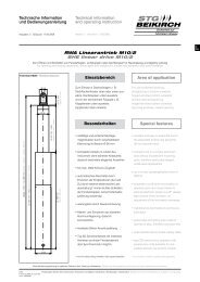
Abmessungen Wind-/ und Regensensor<br />
Wind-/ und Regensensor<br />
Wind / and rain sensor<br />
80<br />
A<br />
43<br />
78°<br />
82<br />
8 66<br />
Bedienung und Einstellung <strong>WRM</strong><strong>40M</strong>-...G<br />
5<br />
160<br />
55<br />
Dimensions wind / and rain alarm<br />
0,25 m<br />
Witterungsbeständiges Kunststoffgehäuse mit Schalenaneometer und beheizter Regensensorfläche.<br />
Weather resistant plastic housing with cup anemometer and heated rain sensor surface.<br />
8<br />
1<br />
2<br />
Ansicht A (gedreht)<br />
view A (rotated)<br />
4<br />
3<br />
10<br />
7<br />
8<br />
Wind-/ und Regensensor mit Standrohr<br />
Wind / and rain sensor with standpipe<br />
9<br />
Operating and setting <strong>WRM</strong><strong>40M</strong>-...G<br />
5 + 6<br />
1<br />
2<br />
3<br />
4<br />
5<br />
6<br />
7<br />
8<br />
9<br />
10<br />
Automatikbetrieb<br />
automatic operation<br />
Handbetrieb<br />
manual operation<br />
Schalterstellung ZU<br />
switch setting CLOSE<br />
LED Netz<br />
LED mains supply<br />
LED Regen<br />
LED rain<br />
LED Wind<br />
LED wind<br />
LED “Zu”<br />
LED “Close”<br />
Windgeschwindigkeit<br />
wind speed<br />
Einschaltverzögerung<br />
switch on delay<br />
Steckbrücken<br />
jumper links<br />
ca.1m<br />
approx. 1 m
Bedienung und Einstellung <strong>WRM</strong><strong>40M</strong>-...G<br />
1 Automatikbetrieb<br />
In der Schalterstellung “Automatik", die Sie über den<br />
Knebelschalter auf der Frontseite des Gehäuses wählen<br />
können, sind keine weiteren Bedienungsschritte mehr notwendig.<br />
Bei Wind, Regen oder Schnee werden die angeschlossenen<br />
Lüftungsaggregate automatisch geschlossen.<br />
Die AUF-Funktion wird erst wieder freigegeben,<br />
- wenn kein Wind, Regen oder Schnee mehr festgestellt wird,<br />
- die Sensorfläche vollständig abgetrocknet ist,<br />
- die Zeitverzögerung abgelaufen ist.<br />
Ein automatisches Auffahren der Lüftungsaggregate ist aus<br />
Sicherheitsgründen nicht vorgesehen.<br />
2 Handbetrieb<br />
In der Schalterstellung “Hand" ist die Wind- und<br />
Regenmeldezentrale außer Betrieb, die Lüftungsaggregate<br />
können über die Lüftungstaster geöffnet und geschlossen<br />
werden. Ein Schließen bei Wind und Regen geschieht nicht.<br />
3 ZU<br />
In der Schalterstellung “ZU” werden alle Lüftungsaggregate<br />
geschlossen und können auch nicht über die Lüftungstaster<br />
geöffnet werden.<br />
4<br />
5<br />
6<br />
7<br />
8<br />
9<br />
10<br />
Auf dem Wind- und Regenmeldemodul informieren 4 LED-<br />
Anzeigen über die Betriebszustände der Anlage.<br />
LED grün (N) leuchtet, wenn die Netzspannung<br />
anliegt und die Anlage betriebsbereit ist.<br />
LED gelb (R) leuchtet, wenn der Regensensor<br />
durch Regen oder Schnee aktiviert ist.<br />
LED gelb (W) leuchtet, wenn die eingestellte<br />
Windgeschwindigkeit und die Einschaltverzögerung<br />
überschritten ist.<br />
LED rot (Zu) leuchtet, wenn die Anlage bei Wind<br />
oder Regen die Antriebe geschlossen hat, die<br />
Ausschaltverzögerung von ca. 2 Min. noch nicht<br />
abgelaufen ist oder der Knebelschalter in<br />
Stellung “Zu” steht.<br />
Windgeschwindigkeit<br />
Über das Potentiometer “Windgeschwindigkeit" kann die<br />
Windgeschwindigkeit ausgewählt werden, bei der die Anlage<br />
die Öffnungsaggregate schließen soll (werkseitige Einstellung<br />
10 m/s).<br />
Einschaltverzögerung<br />
Mit dem Potentiometer “Einschaltverzögerung” kann die Zeit<br />
eingestellt werden, wie lange der Wind mit der eingestellten<br />
Windgeschwindigkeit anstehen muss, bevor die Anlage die<br />
Öffneraggregate schließt (werkseitige Einstellung ca. 15<br />
Sek.).<br />
Steckbrücken<br />
Für Sonderfälle kann mittels der Steckbrücken der Wind- bzw.<br />
Regensensor deaktiviert werden.<br />
1<br />
2<br />
4<br />
3<br />
10<br />
7<br />
8<br />
1<br />
2<br />
3<br />
4<br />
5<br />
6<br />
7<br />
8<br />
9<br />
Automatic operation<br />
No further operating steps are required in the<br />
“Automatic“switch setting that can be selected on the board<br />
using the toggle switch on the front of the housing. The<br />
ventilation units connected close automatically in the event of<br />
wind, rain or snow.<br />
The OPEN function is released again,<br />
- when no more wind, rain or snow is detected,<br />
- the sensor surface is completely dry,<br />
- the time delay has finished.<br />
Automatic actuation of the ventilation units is not intended for<br />
safety reasons.<br />
Manual operation<br />
The wind and rain detection system is out of operation in the<br />
“Manual“ switch setting, the ventilation units can be opened<br />
and closed via the ventilation pushbutton unit. Closing does<br />
not take place in the event of wind and rain.<br />
CLOSE<br />
All ventilation units are closed in the switch setting “CLOSE“<br />
and can also not be opened via the ventilation pushbutton<br />
unit.<br />
LED-displays give information on the wind and rain detection<br />
module on the system operating states.<br />
LED green (N) lights up when the supply voltage is provided<br />
and the system is ready to run.<br />
LED yellow (R) lights up when the rain sensor is activated by<br />
rain or snow.<br />
LED yellow (W) lights up when the set wind speed and the<br />
switch on delay are exceeded.<br />
LED red (close) lights up when the system has closed the<br />
drives in the event of wind or rain, the switch-off delay of<br />
approx. 2 minuntes has not yet expired or the toggle switch<br />
is in the “Close” position.<br />
Wind speed<br />
The wind speed at which the system is to close the opening<br />
units can be selected via the “Wind speed“ potentiometer<br />
(factory setting is 10 m/s).<br />
Switch on delay<br />
The length of time that the wind is to be at the speed set,<br />
before the system closes the opening units is set using the<br />
“Switch on delay“ potentiometer (factory setting is approx. 15<br />
seconds).<br />
10 Jumper links<br />
In special cases the wind or rain sensor can be deactivated<br />
using the jumper links.<br />
9<br />
Operating and setting <strong>WRM</strong><strong>40M</strong>-...G<br />
5 + 6<br />
9<br />
D<br />
GB
10<br />
Abmessungen Zentrale <strong>WRM</strong><br />
AUTOM.<br />
HAND<br />
300<br />
ZU<br />
Kunststoffgehäuse Aufputz mit glasklarer Frontabdeckung (Schutzklasse IP 54).<br />
Surface-mounted plastic housing with clear front cover (type of protection IP 54).<br />
230<br />
<strong>WRM</strong> central control unit dimensions<br />
114