
Create successful ePaper yourself
Turn your PDF publications into a flip-book with our unique Google optimized e-Paper software.
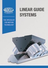
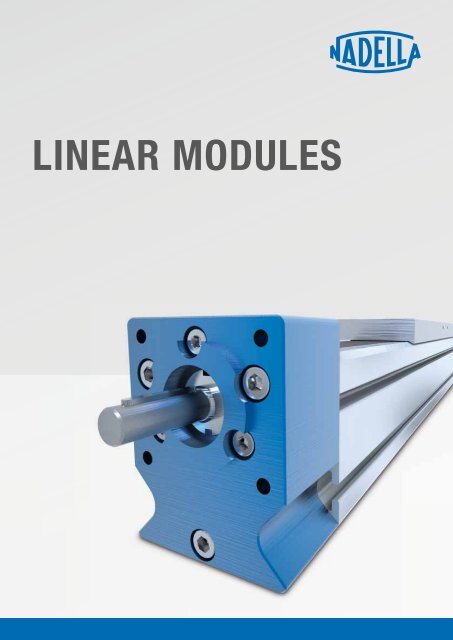
LINEAR MODULES<br />
| 3
2 |
SUMMARY<br />
0<br />
PAGE 4 <strong>–</strong> 7<br />
PAGE 8 <strong>–</strong> 12<br />
PAGE 14 <strong>–</strong> 25<br />
PAGE 26 <strong>–</strong> 35<br />
PAGE 36 <strong>–</strong> 45<br />
PAGE 46 <strong>–</strong> 55<br />
PAGE 56 <strong>–</strong> 70<br />
PAGE 72 <strong>–</strong> 80<br />
1.0 THE <strong>NADELLA</strong> COMPANY<br />
2.0 PRODUCT OVERVIEW<br />
3.0 BASIC-LINE AXN<br />
• Actuator with toothed belt drive and roller guide<br />
4.0 BASIC-LINE AXNP-Z<br />
• Actuator with toothed belt drive and rail or roller guide<br />
5.0 BASIC-LINE AXNP-S<br />
• Actuator with ball screw drive and rail guide<br />
6.0 DRIVE ADAPTION / REFERENCE SWITCH<br />
7.0 FASTENING AND JOINING ELEMENTS<br />
8.0 GENERAL INFORMATION<br />
• Actuator selection<br />
• Technical information<br />
• Calculation<br />
• Type designation<br />
• Application form<br />
| 3
THE <strong>NADELLA</strong> COMPANY<br />
THE SPECIALIST FOR MOTION TECHNOLOGY<br />
<strong>NADELLA</strong> has developed over time from a supplier of rolling bearings, linear guide components and linear axes into an expert system<br />
partner for all areas of motion technology. Wherever innovative ideas, precision and reliability are required, developers and design<br />
engineers rely on products from <strong>NADELLA</strong>. Our customers now include renowned mechanical engineering, plant construction and<br />
automation engineering companies in Germany, Europe, Asia and the USA.<br />
FULL SERVICE AND JUST IN TIME<br />
We consider ourselves to be a full-service partner <strong>–</strong> from<br />
development of a product through production and all the way to<br />
logistics. Our established network guarantees efficient processes in<br />
all areas and throughout the value-added chain <strong>–</strong> all from a single<br />
source. Additionally, express deliveries or fast and inexpensive<br />
special treatment of catalogue parts is also possible. This also<br />
applies to small and medium quantities.<br />
EXPERIENCE AND KNOW-HOW<br />
Professional operations and application consultation are just a<br />
few of our distinguishing characteristics: Our consulting engineers<br />
collaborate closely with our customers’ experts, actively contributing<br />
their specialist expertise, their experience and the technical<br />
possibilities. This results in custom solutions that set standards.<br />
MAXIMUM QUALITY AND CERTIFIED<br />
ENVIRONMENTAL MANAGEMENT<br />
Maximum quality is our top priority. That is why every process step<br />
is accompanied and regularly checked by expert employees. All<br />
companies and plants are certified according to DIN EN ISO 9001<br />
or ISO/TS 16949, and their environmental management systems<br />
comply with DIN EN ISO 14001. We also have the latest measuring<br />
and testing equipment at our disposal to ensure that our high quality<br />
standards are met over the long term.<br />
• CAQ system<br />
• 3-D CNC measuring machines<br />
• Force testing<br />
• Radiographic inspection<br />
• Microsection analysis<br />
• Materials testing on metal and plastic<br />
4 |
1<br />
| 5
WORLDWIDE NETWORK<br />
FOR IDEAL SERVICE<br />
MANY PATHS LEAD TO <strong>NADELLA</strong> <strong>–</strong> AND THEY ARE SHORT<br />
ANYWHERE IN THE WORLD.<br />
Our customers’ satisfaction is the basis for our success and<br />
growth. That is why we are at your service around the world<br />
and always keep your requirements in mind. We now possess a<br />
worldwide network of distributors in all important industrialised<br />
countries in Europe, Asia and the USA. This allows us to ensure<br />
customer-orientated consultation, delivery and service at all times.<br />
<strong>NADELLA</strong> MAIN OFFICES<br />
BRANCHES AND DISTRIBUTORS<br />
China<br />
Germany<br />
Italy<br />
USA<br />
DURBAL HEAD OFFICE<br />
Germany<br />
Belgium<br />
Brazil<br />
Denmark<br />
Finland<br />
France<br />
Great Britain<br />
India<br />
Korea<br />
Netherlands<br />
Norway<br />
Austria<br />
Poland<br />
Romania<br />
Sweden<br />
Switzerland<br />
Singapore<br />
Slovakia<br />
Slovenia<br />
Spain<br />
Taiwan<br />
Czech Republic<br />
Turkey<br />
Hungary<br />
6 |
| 7
8 |
PRODUCT<br />
OVERVIEW<br />
2<br />
PAGE 10<br />
PAGE 11<br />
PAGE 12<br />
2.1 BASIC-LINE AXN<br />
2.2 BASIC-LINE AXNP-Z<br />
2.3 BASIC-LINE AXNP-S<br />
| 9
PRODUCT OVERVIEW<br />
2.1<br />
BASIC-LINE AXN<br />
AXN 45 AXN 65 AXN 80 AXN 100<br />
Profile cross section w x h (mm) 45 x 48 65 x 68.5 80 x 84 100 x 100<br />
Drive Toothed belt Toothed belt Toothed belt Toothed belt<br />
Feed rate (mm/U) 100 150 180 230<br />
Max. dynamic working load (N) 325 650 1450 2500<br />
Repeat accuracy (mm) ± 0.05 ± 0.05 ± 0.05 ± 0.05<br />
Vmax. (m/s) up to 6 10 10 10<br />
Guide system LR24 LR35 LR42<br />
LR52<br />
B 25<br />
Max. total length overall (m) 1) 6 6 6 (8) 6 (8)<br />
Loads (N) dyn. stat. dyn. stat. dyn. stat. dyn. stat.<br />
P R (Roller guide LR) 2) 570 1040 995 2400 1735 3000 2150 3200<br />
P R (Rail guide B) 2) 6000 20000<br />
P L (Roller guide LR) 2) 570 1040 995 2400 1735 3000 2150 3200<br />
P L (Rail guide B) 2) 6000 20000<br />
P T (Roller guide LR) 2) 1030 1810 1940 3200 2950 5250 4500 7000<br />
P T (Rail guide B) 2) 6000 20000<br />
Load moments (Nm)<br />
M x (Roller guide LR) 2) 8 15 20 40 36 62 75 110<br />
M x (Rail guide B) 2) 75 225<br />
M y (Roller guide LR) 2) 16 27 30 75 83 143 125 170<br />
M y (Rail guide B) 2) 500 1650<br />
M z (Roller guide LR) 2) 30 54 70 120 146 260 330 400<br />
M z (Rail guide B) 2) 500 1650<br />
1)<br />
In one part <strong>–</strong> longer version of 8 m upon request<br />
2)<br />
Max. loads and dynamic working loads dependent on guide system<br />
10 |
2.2<br />
Basic-Line AXNP-Z<br />
AXNP 45-Z AXNP 65-Z AXNP 80-Z<br />
Profile cross section w x h (mm) 45 x 48 65 x 68.5 80 x 84<br />
Drive Toothed belt Toothed belt Toothed belt<br />
Feed rate (mm/U) 100 150 180<br />
Max. dynamic working load (N) 325 650 1450<br />
Repeat accuracy (mm) ± 0.05 ± 0.05 ± 0.05<br />
Vmax. (m/s) up to 6 10 10<br />
Guide system<br />
LR24<br />
B 9<br />
LR35<br />
B 15<br />
Max. total length overall (m) 1) 6 6 6<br />
Loads (N) dyn. stat. dyn. stat. dyn. stat.<br />
P R (Roller guide LR) 2) 570 1040 995 2400 1735 3000<br />
P R (Rail guide B) 2) 660 910 2750 9650 4300 15000<br />
P L (Roller guide LR) 2) 570 1040 995 2400 1735 3000<br />
P L (Rail guide B) 2) 660 910 2750 9650 4300 15000<br />
P T (Roller guide LR) 2) 1030 1810 1940 3200 2950 5250<br />
P T (Rail guide B) 2) 660 910 2750 9650 4300 15000<br />
Load moments (Nm)<br />
M x (Roller guide LR) 2) 8 15 20 40 36 62<br />
M x (Rail guide B) 2) 4,5 6 19 69 43 150<br />
M y (Roller guide LR) 2) 16 27 30 75 83 143<br />
M y (Rail guide B) 2) 18 25 95 345 205 730<br />
M z (Roller guide LR) 2) 30 54 70 120 146 260<br />
M z (Rail guide B) 2) 18 25 95 345 205 730<br />
1)<br />
In one part <strong>–</strong> longer version of 8 m upon request<br />
2)<br />
Max. loads and dynamic working loads dependent on guide system<br />
LR42<br />
B 20<br />
| 11
PRODUCT OVERVIEW<br />
2.3<br />
BASIC-LINE AXNP-S<br />
AXNP 45-S AXNP 65-S AXNP 80-S<br />
Profile cross section w x h (mm) 45 x 60 65 x 85 80 x 102<br />
Drive Ball screw Ball screw Ball screw<br />
Pitch (mm) 5 / 10 5 / 10 / 16 5 / 20<br />
Ball screw (mm) Ø 12 Ø 16 Ø 20<br />
Max. dynamic working load (N) 3600 6500 <strong>–</strong> 12000 8000 <strong>–</strong> 17500<br />
Repeat accuracy (mm) ± 0.03 ± 0.03 ± 0.03<br />
Vmax. (m/s) up to 1 1.6 2<br />
Max. total length overall (m) 1) 2 3 4<br />
Moment of inertia (kgcm 2 /m) 0.11 0.33 0.82<br />
Guide system Rail guide B 9 Rail guide B 15 Rail guide B 20<br />
Loads dyn. stat. dyn. stat. dyn. stat.<br />
P R (N) 2) 660 910 1400 3900 5400 15000<br />
P L (N) 2) 660 910 1400 3900 5400 15000<br />
P T (N) 2) 660 910 1400 3900 5400 15000<br />
Load moments<br />
M X (Nm) 2) 5 6 10 30 54 150<br />
M Y (Nm) 2) 20 25 65 185 420 1150<br />
M Z (Nm) 2) 20 25 65 185 420 1150<br />
1)<br />
In one part <strong>–</strong> longer version of 8 m upon request<br />
2)<br />
Max. loads and dynamic working loads dependent on guide system<br />
12 |
NOTES<br />
| 13
14 |
BASIC-LINE<br />
AXN<br />
3<br />
PAGE 16 <strong>–</strong> 17<br />
3.1 PRODUCT DESCRIPTION<br />
Setting, performances, characteristics, applications<br />
and combination examples<br />
PAGE 18 <strong>–</strong> 19 3.2 AXN 45-Z<br />
<strong>Linear</strong> module with toothed drive belt<br />
• Roller guide<br />
• Single, double or long carriage<br />
PAGE 20 <strong>–</strong> 21 3.3 AXN 65-Z<br />
<strong>Linear</strong> module with toothed drive belt<br />
• Roller guide<br />
• Single, double or long carriage<br />
PAGE 22 <strong>–</strong> 23 3.4 AXN 80-Z<br />
PAGE 24 <strong>–</strong> 25 3.5 AXN 100-Z<br />
<strong>Linear</strong> module with toothed drive belt<br />
• Roller guide<br />
• Single, double or long carriage<br />
<strong>Linear</strong> module with toothed drive belt<br />
• Roller guide or recirculating ball guides<br />
• Single, double or long carriage<br />
| 15
BASIC-LINE AXN<br />
PRODUCT DESCRIPTION<br />
Basic-Line AXN stands for a maximum in performance and at the same time for a minimum in cost. Being equipped with toothed belt<br />
drive only, these modules are predestined for quick handling and positioning works. If single module or multi axes system: Depending on<br />
the customer‘s requirements various combinations are possible.<br />
LIFETIME LUBRICATION<br />
The bearings of the rollers and bearings of the pulleys are lubricated<br />
for life. At any movement the steel shafts or the roller guides<br />
are coated by a thin lubricant film, coming from an integrated<br />
system. For short-stroke use, strokes ≤ ½ length of carriage, please<br />
contact our Technical support. In case of high travel mileage<br />
and / or acceleration values it is possible to refill this system<br />
through lubricating nipples in the table plate. (Recommended lubricant:<br />
Klüber Lamora D220)<br />
UNIVERSAL MOTOR CONNECTION<br />
Economic and space-saving solution by direct gearbox connection.<br />
Drive end of the gear is equipped with hollow-shaft connection.<br />
Alternatively, almost all common flange motors can be connected<br />
with the corresponding motor adapters by metal bellow or<br />
elastormer claw couplings.<br />
ASSEMBLY AND FIXATION OF THE ACTUATOR<br />
By end-to-end slots on either side and at the bottom of the actuator profile a universal installation of<br />
the module at your device is possible. Slot nuts that can be swivelled in, fastening strips and connecting<br />
plates increase the mounting flexibility. The actuator itself as well as attachments can easily be<br />
screwed through two longitudinal slots in the table plates (AXN 45 with thread). Alternatively the Basic-<br />
Line can be equipped with additional tables (at fixed distance) or with long carriages. Depending on the<br />
applied load, the high stiffness of the profiles allows for a partly self-supporting use.<br />
16 |
3.1<br />
DIRT PROTECTION<br />
The toothed belt integrated into the profile covers the actuator from<br />
the top and so prevents large dirt particles from penetrating into the<br />
actuator. Wiper brushes integrated in the drive head complete the<br />
protective measures against penetrating dirt. Optionally air purge<br />
connections are available, e. g. in case of extreme dust generation.<br />
TOOTHED BELT<br />
AT-type belt, reinforced with steel cords, allows transfer of large drag<br />
forces and guarantees a long liftime. The belt tension is located in<br />
the crosshead.<br />
ROLLER GUIDE<br />
The characteristic features of the roller guide are cost-saving,<br />
nearly maintenance free and concomitant with high-performance.<br />
Resistance to soiling and smooth running is achieved by rollers of<br />
large dimensions. The use of two eccentric bearings guarantees<br />
that the guides can optimal be pre-loaded and mounted completeley<br />
free of clearance. The dynamic working load is based on a nominal<br />
lifetime of 54.000 km.<br />
| 17
BASIC-LINE AXN<br />
AXN 45-Z<br />
Actuator with toothed belt and roller guide.<br />
Rust-resistant version<br />
available.<br />
NX<br />
Stroke calculation: using distance and safety overrun<br />
Values in brackets for long carriage<br />
Motor connection see chapter Drive adaption<br />
18 |
LOADS AND LOAD MOMENTS*<br />
Roller guide LR 24.06<br />
Loads (N) dyn. stat.<br />
P R 570 (950) 1040 (2000)<br />
P L 570 (950) 1040 (2000)<br />
P T 1030 (1710) 1810 (3500)<br />
Load moments (Nm)<br />
M x 8 (14) 15 (30)<br />
M y 16 (45) 27 (90)<br />
M z 30 (80) 54 (170)<br />
* The dynamic load of the guide system is based on a nominal liftetime of 54000 km<br />
Values in brackets for execution with long carriage (254 mm)<br />
3.2<br />
P R<br />
M x<br />
M y<br />
M z<br />
P L<br />
I Y<br />
P T<br />
I Z<br />
TECHNICAL DATA<br />
Max. speed<br />
Repeating accuracy<br />
Actuation<br />
Max. dynamic working load<br />
Feed rate per rotation<br />
Idle-running torque<br />
max. 6 m/s<br />
± 0.05 mm/m<br />
Toothed belt 16 AT5<br />
325 N<br />
100 mm<br />
0.2 <strong>–</strong> 0.3 Nm<br />
Moment of inertia 0.383 kgcm 2<br />
Max. length overall<br />
6 m<br />
Geometrical moment of inertia I Y 21.7 cm 4<br />
Geometrical moment of inertia I Z 22.5 cm 4<br />
MASS<br />
Basic mass<br />
Mass per 100 mm stroke<br />
Slide mass<br />
Roller guide LR 24.06<br />
1.8 kg<br />
0.3 kg<br />
0.5 kg (1.0 kg)<br />
| 19
BASIC-LINE AXN<br />
AXN 65-Z<br />
Actuator with toothed belt and roller guide.<br />
Rust-resistant version<br />
available.<br />
NX<br />
Stroke calculation: using distance and safety overrun<br />
Values in brackets for long carriage<br />
Motor connection see chapter Drive adaption<br />
20 |
LOADS AND LOAD MOMENTS*<br />
Roller guide LR 35.10<br />
Loads (N) dyn. stat.<br />
P R 995 (1700) 2400 (4500)<br />
P L 995 (1700) 2400 (4500)<br />
P T 1940 (3500) 3200 (6500)<br />
Load moments (Nm)<br />
M x 20 (40) 40 (80)<br />
M y 30 (112) 75 (250)<br />
M z 70 (220) 120 (400)<br />
* The dynamic load of the guide system is based on a nominal liftetime of 54000 km<br />
Values in brackets for execution with long carriage (350 mm)<br />
3.3<br />
P R<br />
M x<br />
M y<br />
M z<br />
P L<br />
I Y<br />
P T<br />
I Z<br />
TECHNICAL DATA<br />
Max. speed<br />
Repeating accuracy<br />
Actuation<br />
Max. dynamic working load<br />
Feed rate per rotation<br />
Idle-running torque<br />
max. 10 m/s<br />
± 0.05 mm/m<br />
Toothed belt 32 AT5<br />
650 N<br />
150 mm<br />
0.8 <strong>–</strong> 1.0 Nm<br />
Moment of inertia 2.994 kgcm 2<br />
Max. length overall 6 m (one-piece) 1)<br />
Geometrical moment of inertia I Y 80.2 cm 4<br />
Geometrical moment of inertia I Z 89.2 cm 4<br />
1)<br />
Major length upon request<br />
MASS<br />
Basic mass<br />
Mass per 100 mm stroke<br />
Slide mass<br />
Roller guide LR 35.10<br />
4.8 kg<br />
0.6 kg<br />
1.5 kg (3 kg)<br />
| 21
BASIC-LINE AXN<br />
AXN 80-Z<br />
Actuator with toothed belt and roller guide.<br />
Rust-resistant version<br />
available.<br />
NX<br />
Stroke calculation: using distance and safety overrun<br />
Values in brackets for long carriage<br />
Motor connection see chapter Drive adaption<br />
22 |
LOADS AND LOAD MOMENTS*<br />
Roller guide LR 42.10<br />
Loads (N) dyn. stat.<br />
P R 1735 (2950) 3000 (5100)<br />
P L 1735 (2950) 3000 (5100)<br />
P T 2950 (5000) 5250 (8900)<br />
Load moments (Nm)<br />
M x 36 (60) 62 (100)<br />
M y 83 (245) 143 (425)<br />
M z 146 (365) 260 (635)<br />
* The dynamic load of the guide system is based on a nominal liftetime of 54000 km<br />
Values in brackets for execution with long carriage (460 mm)<br />
3.4<br />
P R<br />
M x<br />
M y<br />
M z<br />
P L<br />
I Y<br />
P T<br />
I Z<br />
TECHNICAL DATA<br />
Max. speed<br />
Repeating accuracy<br />
Actuation<br />
Max. dynamic working load<br />
Feed rate per rotation<br />
Idle-running torque<br />
max. 10 m/s<br />
± 0.05 mm/m<br />
Toothed belt 32 AT10<br />
1450 N<br />
180 mm<br />
1.0 <strong>–</strong> 1.2 Nm<br />
Moment of inertia 5.237 kgcm 2<br />
Max. length overall 6 m (one-piece) 1)<br />
Geometrical moment of inertia I Y 198.5 cm 4<br />
Geometrical moment of inertia I Z 207.4 cm 4<br />
1)<br />
Major length upon request, 8 m in one piece dependent on availability<br />
MASS<br />
Basic mass<br />
Mass per 100 mm stroke<br />
Slide mass<br />
Roller guide LR 42.10<br />
8.5 kg<br />
0.9 kg<br />
2.3 (4.6) kg<br />
| 23
BASIC-LINE AXN<br />
AXN 100-Z<br />
Actuator with toothed belt and roller or rail guide.<br />
Rust-resistant version<br />
available.<br />
NX<br />
Stroke calculation: using distance and safty overrun<br />
Values in brackets for long carriage<br />
Motor connection see chapter Drive adaption<br />
24 |
LOADS AND LOAD MOMENTS*<br />
3.5<br />
Roller guide LR 52.16 Rail guide B 25<br />
Loads (N) dyn. stat. dyn. stat.<br />
P R 2150 (3500) 3200 (7500) 6000 (8000) 20000 (30000)<br />
P L 2150 (3500) 3200 (7500) 6000 (8000) 20000 (30000)<br />
P T 4500 (7800) 7000 (13000) 6000 (8000) 20000 (30000)<br />
Load moments (Nm)<br />
M x 75 (125) 110 (340) 75 (90) 225 (800)<br />
M y 125 (425) 170 (850) 500 (600) 1650 (2300)<br />
M z 330 (430) 400 (1900) 500 (600) 1650 (2300)<br />
* The dynamic load of the guide system is based on a nominal liftetime of 54000 km<br />
Values in brackets for execution with long carriage (580 mm)<br />
P R<br />
M x<br />
M y<br />
M z<br />
P L<br />
I Y<br />
P T<br />
I Z<br />
TECHNICAL DATA<br />
Max. speed max. 10 m/s (LR 52.16)<br />
Repeating accuracy<br />
Actuation<br />
Max. dynamic working load<br />
Feed rate per rotation<br />
Idle-running torque<br />
± 0.05 mm/m<br />
Toothed belt 50 AT10<br />
2500 N<br />
230 mm<br />
3 Nm<br />
Moment of inertia 14 kgcm 2<br />
Max. length overall 6 m (8m) 1)<br />
Geometrical moment of inertia I Y 343 cm 4<br />
Geometrical moment of inertia I Z 465 cm 4<br />
1)<br />
Major length upon request, 8 m in one piece dependent on availability<br />
MASS<br />
Roller guide LR 52.16 Rail guide B 25<br />
Basic mass 16 kg 15.4 kg<br />
Mass per 100 mm stroke 1.4 kg 1.4 kg<br />
Slide mass 4.4 kg (6.4 kg) 3.8 kg (5.8 kg)<br />
| 25
26 |
BASIC-LINE<br />
AXNP-Z<br />
4<br />
PAGE 28 <strong>–</strong> 29<br />
4.1 PRODUCT DESCRIPTION<br />
Setting, performances, characteristics, applications<br />
and combination examples<br />
PAGE 30 <strong>–</strong> 31 4.2 AXNP 45-Z<br />
<strong>Linear</strong> module with toothed drive belt with or without cover band<br />
• Roller guide or recirculating ball guide<br />
• Single, double or long carriage<br />
PAGE 32 <strong>–</strong> 33 4.3 AXNP 65-Z<br />
<strong>Linear</strong> module with toothed drive belt with or without cover band<br />
• Roller guide or recirculating ball guide<br />
• Single, double or long carriage<br />
PAGE 34 <strong>–</strong> 35 4.4 AXNP 80-Z<br />
<strong>Linear</strong> module with toothed drive belt with or without cover band<br />
• Roller guide or recirculating ball guide<br />
• Single, double or long carriage<br />
| 27
BASIC-LINE AXNP-Z<br />
PRODUCT DESCRIPTION<br />
The new range of AXNP modules is a further development of our successful AXN modules with toothed drive belt. These units have been<br />
developed especially for quick handling and positioning functions. If individual or multi system <strong>–</strong> depending on customers’ requirements<br />
various combinations are possible, even a combination with the AXN module range is possible.<br />
UNIVERSAL MOTOR<br />
CONNECTION<br />
DIRT PROTECTION<br />
The actuator profile of the basic line modules AXNP contains a<br />
cover band which covers the profile completely on the upper side.<br />
Therefore, dirt particles can not enter into the actuator. In additon,<br />
wiper brushes integrated in the head covers prevent effectively<br />
larger dirt particles from penetrating into the profile. Of course all<br />
actuators can also be delivered without cover band.<br />
Economic and space-saving<br />
solution by direct gearbox<br />
connection. Drive end of the gear<br />
is equipped with hollow-shaft<br />
connection. Alternatively, almost<br />
all common flange motors can<br />
be connected with the corresponding<br />
motor by metal bellow<br />
or elastomer claw couplings<br />
with the corresponding motor<br />
adapters.<br />
ROLLER GUIDE<br />
The characteristic features of the roller guide are cost-saving, nearly<br />
maintenance free and concomitant with high-performance. Resistance<br />
to soiling and smooth running is achieved by rollers of large<br />
dimensions. The use of two eccentric bearings guarantees that the<br />
guides can optimal be pre-loaded and mounted completeley free of<br />
clearance. The dynamic working load is based on a nominal lifetime<br />
of 54.000 km.<br />
RAIL GUIDE<br />
As an alternative, these actuators can also be equipped with<br />
recirculating ball guides or guides in caged-ball technology.<br />
The advantages of these rail guides are long lifetime, low noise,<br />
high accuracy and high loads. For a statically cycling of the guide<br />
systems the dynamic loads are relevant.<br />
28 |
4.1<br />
ASSEMBLY AND FIXATION OF THE ACTUATOR<br />
By end-to-end slots at the bottom and on either side of the acutator profile a universal installation of the<br />
module is possible. Slot nuts that can be swivelled in, fastening strips and connecting plates increase<br />
the mounting flexibility. Attachments can simply be screwed through threads in the table plate. Alternatively<br />
Basic-Line can be equipped with additional table carriages (fixed distance) or with a long carriage.<br />
Depending on the applied load, the high stiffness of the profiles allows for a partly self-supporting use.<br />
TOOTHED DRIVE BELT<br />
AT-type belt, reinforced with steel cords, allows transfer of large drag<br />
forces and guarantees a long liftime. The belt tension is located in<br />
the crosshead.<br />
LIFETIME LUBRICATION<br />
The bearings of the rollers and bearings of the pulleys are lubricated for life. At any movement the steel<br />
shafts or the roller guides are coated by a thin lubricant film, coming from an integrated system. For<br />
short-stroke use, strokes ≤ ½ length of carriage, please contact our Technical support. In case of high<br />
travel mileage and / or acceleration values it is possible to refill this system through lubricating nipples in<br />
the table plate. Recommended lubricant: Klüber Lamora D220 (guide rollers), Klüber Microlube GL261<br />
(guide rails).<br />
| 29
BASIC-LINE AXNP-Z<br />
AXNP 45-Z<br />
Actuator with toothed belt and roller or rail guide.<br />
Rust-resistant version<br />
available.<br />
NX<br />
Stroke calculation: using distance and safety overrun<br />
Values in brackets for long carriage<br />
Motor connection see chapter Drive adaption<br />
30 |
LOADS AND LOAD MOMENTS*<br />
4.2<br />
Roller guide LR 24.06 Rail guide B 9<br />
Loads (N) dyn. stat. dyn. stat.<br />
P R 570 (950) 1040 (2000) 660 910<br />
P L 570 (950) 1040 (2000) 660 910<br />
P T 1030 (1710) 1810 (3500) 660 910<br />
Load moments (Nm)<br />
M x 8 (14) 15 (30) 4.5 6<br />
M y 16 (45) 27 (90) 18 25<br />
M z 30 (80) 54 (170) 18 25<br />
* The dynamic load of the guide system is based on a nominal liftetime of 54000 km<br />
Values in brackets for execution with long carriage. Long carriage with rail guide upon request<br />
P R<br />
M x<br />
M y<br />
M z<br />
P L<br />
I Y<br />
P T<br />
I Z<br />
TECHNICAL DATA<br />
Max. speed max. 6 m/s (LR 24.06)<br />
Repeating accuracy<br />
Actuation<br />
Max. dynamic working load<br />
Feed rate per rotation<br />
Idle-running torque<br />
± 0.05 mm/m<br />
Toothed belt 16 AT5<br />
325 N<br />
100 mm<br />
0.2 <strong>–</strong> 0.3 Nm<br />
Moment of inertia 0.383 kgcm 2<br />
Max. length overall<br />
6 m<br />
Geometrical moment of inertia I Y 21.7 cm 4<br />
Geometrical moment of inertia I Z 22.5 cm 4<br />
MASS<br />
Roller guide LR 24.06 Rail guide B 9<br />
Basic mass 1.8 kg 1.8 kg<br />
Mass per 100 mm stroke 0.3 kg 0.35 kg<br />
Slide mass with cover band 0.55 kg (1.05 kg) 0.55 kg<br />
Slide mass w/o cover band 0.5 kg (1.00 kg) 0.5 kg<br />
| 31
BASIC-LINE AXNP-Z<br />
AXNP 65-Z<br />
Actuator with toothed belt and roller or rail guide.<br />
Rust-resistant version<br />
available.<br />
NX<br />
Falsche Zeichnung <strong>–</strong> gezeigt wird<br />
AXN65 und nicht AXNP65.<br />
Stroke calculation: using distance and safety overrun<br />
Values in brackets for long carriage<br />
Motor connection see chapter Drive adaption<br />
32 |
LOADS AND LOAD MOMENTS*<br />
4.3<br />
Roller guide LR 35.10 Rail guide B 15<br />
Loads (N) dyn. stat. dyn. stat.<br />
P R 995 (1700) 2400 (4500) 2750 9650<br />
P L 995 (1700) 2400 (4500) 2750 9650<br />
P T 1940 (3500) 3200 (6500) 2750 9650<br />
Load moments (Nm)<br />
M x 20 (40) 40 (80) 19 69<br />
M y 30 (112) 75 (250) 95 345<br />
M z 70 (220) 120 (400) 95 345<br />
* The dynamic load of the guide system is based on a nominal liftetime of 54000 km<br />
Values in brackets for execution with long carriage. Long carriage with rail guide upon request<br />
P R<br />
M x<br />
M y<br />
M z<br />
P L<br />
I Y<br />
P T<br />
I Z<br />
TECHNICAL DATA<br />
Max. speed max. 10 m/s (LR 35.10)<br />
Repeating accuracy<br />
Actuation<br />
Max. dynamic working load<br />
Feed rate per rotation<br />
Idle-running torque<br />
± 0.05 mm/m<br />
Toothed belt 32 AT5<br />
650 N<br />
150 mm<br />
0.8 <strong>–</strong> 1.0 Nm<br />
Moment of inertia 2.994 kgcm 2<br />
Max. length overall 6 m (one-piece) 1)<br />
Geometrical moment of inertia I Y 80.2 cm 4<br />
Geometrical moment of inertia I Z 89.2 cm 4<br />
1)<br />
Major length upon request<br />
MASS<br />
Roller guide LR 35.10 Rail guide B 15<br />
Basic mass 4.8 kg 4.8 kg<br />
Mass per 100 mm stroke 0.6 kg 0.7 kg<br />
Slide mass with cover band 1.6 kg (3.2 kg) 1.7 kg<br />
Slide mass w/o cover band 1.4 kg (3.00 kg) 1.5 kg<br />
Values in brackets for execution with long carriage<br />
| 33
BASIC-LINE AXNP-Z<br />
AXNP 80-Z<br />
Actuator with toothed belt and roller or rail guide.<br />
Rust-resistant version<br />
available.<br />
NX<br />
Stroke calculation: using distance and safety overrun<br />
Values in brackets for long carriage<br />
Motor connection see chapter Drive adaption<br />
34 |
LOADS AND LOAD MOMENTS*<br />
4.4<br />
Roller guide LR 42.10 Rail guide B 20<br />
Loads (N) dyn. stat. dyn. stat.<br />
P R 1735 (2950) 3000 (5100) 4300 15000<br />
P L 1735 (2950) 3000 (5100) 4300 15000<br />
P T 2950 (5000) 5250 (8900) 4300 15000<br />
Load moments (Nm)<br />
M x 36 (60) 62 (100) 43 150<br />
M y 83 (245) 143 (425) 205 730<br />
M z 146 (365) 260 (635) 205 730<br />
* The dynamic load of the guide system is based on a nominal liftetime of 54000 km<br />
Values in brackets for execution with long carriage. Long carriage with rail guide upon request<br />
P R<br />
M x<br />
M y<br />
M z<br />
P L<br />
I Y<br />
P T<br />
I Z<br />
TECHNICAL DATA<br />
Max. speed max. 10 m/s (LR 42.10)<br />
Repeating accuracy<br />
Actuation<br />
Max. dynamic working load<br />
Feed rate per rotation<br />
Idle-running torque<br />
± 0.05 mm/m<br />
Toothed belt 32 AT10<br />
1450 N<br />
180 mm<br />
1.0 <strong>–</strong> 1.2 Nm<br />
Moment of inertia 5.237 kgcm 2<br />
Max. length overall 6 m (one-piece) 1)<br />
Geometrical moment of inertia I Y 198.5 cm 4<br />
Geometrical moment of inertia I Z 207.4 cm 4<br />
1)<br />
Major length upon request, 8 m in one piece dependent on availability<br />
MASS<br />
Roller guide LR 42.10 Rail guide B 20<br />
Basic mass 8.5 kg 8.5 kg<br />
Mass per 100 mm stroke 1.00 kg 1.1 kg<br />
Slide mass with cover band 3.2 kg (6.4 kg) 3.1 kg<br />
Slide mass w/o cover band 2.7 kg (3.1 kg) 2.7 kg<br />
Values in brackets for execution with long carriage<br />
| 35
36 |
BASIC-LINE<br />
AXNP-S<br />
5<br />
PAGE 38 <strong>–</strong> 39<br />
5.1 PRODUCT DESCRIPTION<br />
Setting, performances, characteristics, applications<br />
and combination examples<br />
PAGE 40 <strong>–</strong> 41 5.2 AXNP 45-S<br />
<strong>Linear</strong> module with spindle drive<br />
• Rail guide<br />
• Single or double carriage<br />
PAGE 42 <strong>–</strong> 43 5.3 AXNP 65-S<br />
<strong>Linear</strong> module with spindle drive<br />
• Rail guide<br />
• Single or double carriage<br />
PAGE 44 <strong>–</strong> 45 5.5 AXNP 80-S<br />
<strong>Linear</strong> module with spindle drive<br />
• Rail guide<br />
• Single or double carriage<br />
| 37
BASIC-LINE AXNP-S<br />
PRODUCT DESCRIPTION<br />
The model range AXNP-S is a further development of our approved AXN / AXNP-Z series with toothed belt drive. The modules have been<br />
developed especially for handling and positioning, primarily for precise positioning and vertical applications. If individual module or<br />
multiple axis system - various combinations are possible.<br />
DIRT PROTECTION<br />
On the upper side the actuator is completely covered by a cover<br />
band which is clipped in the profile so that it prevents dirt particles<br />
from penetrating into the module. Wiper brushes integrated in the<br />
table plate as well as an overlapping of the table plate over the main<br />
profile minimize the gap additionally.<br />
MOTOR CONNECTION<br />
A motor can be mounted through<br />
a flange / coupling combination<br />
which is availabe for many motor<br />
types. If technically possible also<br />
special motors can be connected.<br />
RAIL GUIDE<br />
The AXNP-S series is equipped with high-quality ball rail systems.<br />
The advantages of these rail guides are long service life, low noise<br />
level, high guidance accuracy and high load values. For statically<br />
cycling of the guide systems the dynamic load rating is decisive for<br />
the dimensioning of the guide systems.<br />
38 |
5.1<br />
FIXATION OF THE ACTUATOR AND ATTACHEMENTS<br />
By end-to-end slots at the bottom and on either side of the acutator profile a universal installation of the<br />
module is possible. Slot nuts that can be swivelled in, fastening strips and connecting plates increase the<br />
mounting flexibility. Attachments can simply be screwed through threads in the table plate. Alternatively<br />
the Basic-Line can be extended by an additional, non-driven carriage.<br />
SCREW DRIVE<br />
We use standard highly precise whirled ball screw drives. Due<br />
to the hard whirling technology a better surface quality can be<br />
reached compared to ground spindles. The spindles we use are in<br />
the accuracy range of 23 μm / 300 mm (IT5). To support the ball<br />
screw drive in case of larger strokes optionally spindle supports are<br />
available which prevent oscillations and thus allow higher speeds.<br />
LUBRICATION<br />
The bearings of the linear actuators are lubricated for life. The ball<br />
rail system and the ball screw drive can be re-lubricated through<br />
separate lubricating nipples at the carriage that are accessible from<br />
the outside. Especially in case of a high running performance and / or<br />
high acceleration values this is an advantage. For short-stroke use,<br />
strokes ≤ ½ length of carriage, please contact our Technical support.<br />
We recommend the lubricant Klüber Microlube GL261.<br />
| 39
BASIC-LINE AXNP-S<br />
AXNP 45-S<br />
<strong>Linear</strong> actuator with ball screw drive and rail guide.<br />
Lubrication nipple<br />
Stroke calculation: effective stroke + safety overrun<br />
SA = number of spindle support sets<br />
For motor connection see chapter drive adaption<br />
Lubrication: S = ball screw; F = rail guide<br />
40 |
LOADS AND LOAD MOMENTS*<br />
Rail guide B 9<br />
Loads (N) dyn. stat.<br />
P R 660 910<br />
P L 660 910<br />
P T 660 910<br />
Load moments (Nm)<br />
M x 5 6<br />
M y 20 25<br />
M z 20 25<br />
* The dynamic load of the guide system is based on a nominal lifetime of 54000 km<br />
5.2<br />
P R<br />
M x<br />
M y<br />
M z<br />
P L<br />
I Y<br />
P T<br />
I Z<br />
TECHNICAL DATA<br />
Max. speed<br />
1 m/s<br />
Repeating accuracy<br />
± 0.03 mm<br />
Actuation<br />
Ball screw Ø 12 mm<br />
Max. dynamic working load<br />
3600 N<br />
Pitch<br />
5 / 10 mm<br />
Idle-running torque<br />
0.4 Nm<br />
Moment of inertia 0.11 kgcm 2 /m<br />
Max. length overall<br />
2 m<br />
Geometrical moment of inertia I Y 20.3 cm 4<br />
Geometrical moment of inertia I Z 21.7 cm 4<br />
MASS<br />
Basic mass<br />
Mass per 100 mm stroke<br />
Slide mass<br />
Rail guide B 9<br />
1.6 kg<br />
0.4 kg<br />
0.45 kg<br />
speed (min.-1)<br />
stroke length (mm)<br />
without SA<br />
1 SA<br />
SA = 1 set of spindle support<br />
| 41
BASIC-LINE AXNP-S<br />
AXNP 65-S<br />
<strong>Linear</strong> actuator with ball screw drive and rail guide.<br />
Lubrication nipple<br />
Stroke calculation: effective stroke + safety overrun<br />
SA = number of spindle support sets<br />
For motor connection see chapter drive adaption<br />
Lubrication: S = ball screw; F = rail guide<br />
42 |
LOADS AND LOAD MOMENTS*<br />
Rail guide B 15<br />
Loads (N) dyn. stat.<br />
P R 1400 3900<br />
P L 1400 3900<br />
P T 1400 3900<br />
Load moments (Nm)<br />
M x 10 30<br />
M y 65 185<br />
M z 65 185<br />
* The dynamic load of the guide system is based on a nominal lifetime of 54000 km<br />
5.3<br />
P R<br />
M x<br />
M y<br />
M z<br />
P L<br />
I Y<br />
P T<br />
I Z<br />
TECHNICAL DATA<br />
Max. speed<br />
1.6 m/s<br />
Repeating accuracy<br />
± 0.03 mm<br />
Actuation<br />
Ball screw Ø 16 mm<br />
Max. dynamic working load<br />
6500 <strong>–</strong> 12000 N<br />
Pitch<br />
5 / 10 / 16 mm<br />
Idle-running torque<br />
0.5 Nm<br />
Moment of inertia 0.33 kgcm 2 /m<br />
Max. length overall<br />
3 m<br />
Geometrical moment of inertia I Y 76.3 cm 4<br />
Geometrical moment of inertia I Z 87.3 cm 4<br />
MASS<br />
Basic mass<br />
Mass per 100 mm stroke<br />
Slide mass<br />
Rail guide B 15<br />
4.6 kg<br />
0.8 kg<br />
1.4 kg<br />
speed (min.-1)<br />
stroke length (mm)<br />
without SA 1 SA 2 SA 3 SA<br />
SA = 1 set of spindle support<br />
| 43
BASIC-LINE AXNP-S<br />
AXNP 80-S<br />
<strong>Linear</strong> actuator with ball screw drive and rail guide.<br />
Lubrication nipple<br />
Stroke calculation: effective stroke + safety overrun<br />
SA = number of spindle support sets<br />
For motor connection see chapter drive adaption<br />
Lubrication: S = ball screw; F = rail guide<br />
44 |
LOADS AND LOAD MOMENTS*<br />
Rail guide B 20<br />
Loads (N) dyn. stat.<br />
P R 5400 15000<br />
P L 5400 15000<br />
P T 5400 15000<br />
Load moments (Nm)<br />
M x 54 150<br />
M y 420 1150<br />
M z 420 1150<br />
* The dynamic load of the guide system is based on a nominal lifetime of 54000 km<br />
5.4<br />
P R<br />
M x<br />
M y<br />
M z<br />
P L<br />
I Y<br />
P T<br />
I Z<br />
TECHNICAL DATA<br />
Max. speed<br />
2 m/s<br />
Repeating accuracy<br />
± 0.03 mm<br />
Actuation<br />
Ball screw Ø 20 mm<br />
Max. dynamic working load<br />
8000 <strong>–</strong> 17500 N<br />
Pitch<br />
5 / 20 mm<br />
Idle-running torque<br />
0.6 Nm<br />
Moment of inertia 0.82 kgcm 2 /m<br />
Max. length overall<br />
4 m<br />
Geometrical moment of inertia I Y 193.5 cm 4<br />
Geometrical moment of inertia I Z 207.1 cm 4<br />
MASS<br />
Basic mass<br />
Mass per 100 mm stroke<br />
Slide mass<br />
Rail guide B 20<br />
8.6 kg<br />
1.2 kg<br />
2.7 kg<br />
speed (min.-1)<br />
stroke length (mm)<br />
without SA 1 SA 2 SA 3 SA 4 SA<br />
SA = 1 set of spindle support<br />
| 45
46 |
6<br />
REFERENCE SWITCH<br />
DRIVE ADAPTION /<br />
PAGE 48<br />
PAGE 49<br />
PAGE 50 <strong>–</strong> 51<br />
PAGE 52 <strong>–</strong> 53<br />
PAGE 54 <strong>–</strong> 55<br />
6.1 FREE SHAFT EXTENSION<br />
6.2 DIRECT GEARBOX CONNECTION<br />
6.3 GEAR / MOTOR ADAPTION WITH COUPLING<br />
6.4 DRIVE CONNECTING SHAFT VBW AND DRIVE CONNECTION VBR<br />
WITH PARTIALLY INTEGRATED COUPLING KL RESP. KR AT THE AXIS<br />
(DIRECT CONNECTION FOR GEARBOX)<br />
6.5 INDUCTIVE END / REFERENCE SWITCH<br />
• Inductive switches<br />
| 47
6.1<br />
DRIVE ADAPTION<br />
FREE SHAFT EXTENSION<br />
Optional drive shafts on one or both sides for drive connection e.g. with gearbox.<br />
Type a b H7 c 1) d H6 d 2 e1 2) min. e f g l s<br />
AXN(P) 45-Z 28.5 37 x 1.7 0 12 0 37 47 17.5 7.5 20 M4 x 6<br />
AXN(P) 65-Z 40 55 x 1.5 0 14 0 56 67 23.4 11.6 30 M5 x 9.5<br />
AXN(P) 80-Z 46 62 x 3 0 20 0 68 77 24.5 15.5 30 M6 x 12<br />
AXN 100-Z 60 80 x 2 0 25 0 95 80 32.3 19.7 35 M6 x 12<br />
1)<br />
„0“ = Shaft snag on the opposite side is almost flush with outer edge of profile<br />
2)<br />
Only lower profile nut with type AXN(P)<br />
Example Order Code<br />
WL = shaft left<br />
WR = shaft right<br />
AXNP45-Z WL12-LR24-500-749-00<br />
48 |
DIRECT GEARBOX CONNECTION<br />
6.2<br />
Space-saving drive connection with adapter plate and standard gear. Advantages are improvement of space and cost reduction due<br />
to removal of clutch and clutch bell. The drive is connected with the actuator via adapter plate. Power transmission to be effected by<br />
fitted key.<br />
motor shaft<br />
GEAR DATA<br />
Actuator type AXN(P) 45-Z AXN(P) 65-Z AXN(P) 80-Z AXN 100-Z<br />
Gear type PLE 40 PLE 60 PLE 80 PLE 120<br />
Gear ratio 1) 3, 4, 5, 8<br />
Max. output torque T (Nm) 5 15 40 4) 90 4)<br />
Max. medium rotary speed<br />
at 50 % T (min -1 )<br />
5000 4500 4000 3350<br />
Circumferential backlash<br />
(arcmin) 2) < 15 < 12 < 8 < 8<br />
Moment of inertia (kgcm 2 ) 3) 0.031 <strong>–</strong> 0.017 0.135 <strong>–</strong> 0.065 0.77 <strong>–</strong> 0.39 2.63 <strong>–</strong> 1.32<br />
Weight (kg) 0.35 0.9 2.1 6<br />
1)<br />
Other gear ratio upon request<br />
2)<br />
Restricted circumferential backlash<br />
3)<br />
Depending on gear ratio<br />
4)<br />
reduced when using VBR<br />
DIMENSIONS<br />
Actuator type<br />
Gear<br />
type<br />
e 5)<br />
(mm)<br />
Motor<br />
type<br />
b 5)<br />
(mm)<br />
max. weight<br />
of motor<br />
(kg)<br />
d<br />
i max.<br />
(mm)<br />
K max. 6)<br />
(mm)<br />
AXN(P)45-Z PLE 40 any B5 / B14 any 2 4 / 5 / 6 / 6.35 / 8 / 9 / 11 25 40 x 40 74<br />
AXN(P)65-Z PLE 60 any B5 / B14 any 3.5<br />
AXN(P)80-Z PLE 80 any B5 / B14 any 9<br />
AXN100-Z PLE 120 any B5 / B14 any 16.5<br />
5)<br />
Within flange dimensions<br />
6)<br />
Max. dimenison, next higher ones on request (e. g.: PLE 40 with flange dimensions 60 x 60 mm)<br />
7)<br />
Length of motor flange included<br />
6 / 6.35 / 8 / 9 / 9.525 /<br />
10 / 11 / 12 / 14 / 16 / 19<br />
9.525 / 10 / 11 / 12<br />
12.7 / 14 / 16 / 19 / 22 / 24<br />
11 / 12.7 / 14 / 15.87 /<br />
16 / 19 / 22 / 24 / 28 /<br />
32 / 35<br />
L 7)<br />
(mm)<br />
23 60 x 60 77.5<br />
30 90 x 90 106<br />
40 115 x 115 134.5<br />
Example Order Code<br />
i3 =, gear left<br />
AXNP45-Z PL3-LR24-500-794-00<br />
| 49
DRIVE ADAPTION<br />
GEAR / MOTOR ADAPTION WITH COUPLING<br />
Gear / motor adaption through standardized mounting combinations with coupling, coupling bell and adapter flange.<br />
AXN(P)<br />
motor- / gear shaft<br />
Example Order Code left side<br />
AXNP45-Z MKL-LR24-500-794-00<br />
AXNP-S<br />
motor- / gear shaft<br />
Example Order Code<br />
AXNP45-S MK-B-100-326-00<br />
50 |
6.3<br />
AXN(P)<br />
Actuator Code Design e α s b d i K a L<br />
min. <strong>–</strong> max. min. <strong>–</strong> max. max. max.<br />
AXN(P) 45-Z I B5 45 <strong>–</strong> 65 0° 4 x M5 x 15 36 <strong>–</strong> 55 6 <strong>–</strong> 16 35 75 100 57<br />
II B5 45 <strong>–</strong> 90 45° 4 x M5 x 15 36 <strong>–</strong> 70 6 <strong>–</strong> 16 35 75 100 57<br />
III B14 50 <strong>–</strong> 63 0° 4 x Ø 5.5 36 <strong>–</strong> 55 6 <strong>–</strong> 16 35 75 100 57<br />
IV B14 50 <strong>–</strong> 86 45° 4 x Ø 5.5 36 <strong>–</strong> 72 6 <strong>–</strong> 16 35 75 100 57<br />
AXN(P) 65-Z I B5 65 <strong>–</strong> 110 0° 4 x M5 x 18 52 <strong>–</strong> 100 8 <strong>–</strong> 28 40 90 120 72.5<br />
II B5 65 <strong>–</strong> 110 45° 4 x M5 x 18 52 <strong>–</strong> 100 8 <strong>–</strong> 28 40 90 120 72.5<br />
III B14 68 <strong>–</strong> 110 0° 4 x Ø 5.5 52 <strong>–</strong> 100 8 <strong>–</strong> 28 40 90 120 72.5<br />
IV B14 68 <strong>–</strong> 110 45° 4 x Ø 5.5 52 <strong>–</strong> 100 8 <strong>–</strong> 28 40 90 120 72.5<br />
AXN(P) 80-Z I B5 75 <strong>–</strong> 110 0° 4 x M6 x 12 60 <strong>–</strong> 95 12 <strong>–</strong> 32 45 120 130 77<br />
II B5 75 <strong>–</strong> 120 45° 4 x M6 x 12 60 <strong>–</strong> 105 12 <strong>–</strong> 32 45 120 130 77<br />
III B14 80 <strong>–</strong> 105 0° 4 x Ø 6.6 60 <strong>–</strong> 95 12 <strong>–</strong> 32 45 120 130 77<br />
IV B14 80 <strong>–</strong> 115 45° 4 x Ø 6.6 60 <strong>–</strong> 105 12 <strong>–</strong> 32 45 120 130 77<br />
AXN 100 I B5 75 <strong>–</strong> 108 0° 4 x M6 x 16 60 <strong>–</strong> 96 12 <strong>–</strong> 32 45 120 150 98.5<br />
II B5 75 <strong>–</strong> 138 45° 4 x M6 x 16 60 <strong>–</strong> 115 12 <strong>–</strong> 32 45 120 150 98.5<br />
III B14 82 <strong>–</strong> 110 0° 4 x Ø 6.6 60 <strong>–</strong> 100 12 <strong>–</strong> 32 45 120 150 98.5<br />
IV B14 82 <strong>–</strong> 140 45° 4 x Ø 6.6 60 <strong>–</strong> 115 12 <strong>–</strong> 32 45 120 150 98.5<br />
AXNP-S<br />
Actuator Code Design e α S b d i K L<br />
min. <strong>–</strong> max. min. <strong>–</strong> max. min. <strong>–</strong> max. max. max.<br />
AXNP 45-S I B5 44 <strong>–</strong> 53 0° 4 x M5 x 12 35 <strong>–</strong> 45 4 <strong>–</strong> 16 34 60 60<br />
II B5 50 <strong>–</strong> 70 45° 4 x M5 x 12 35 <strong>–</strong> 58 4 <strong>–</strong> 16 34 60 60<br />
III B14 54 <strong>–</strong> 70 45° 4 x Ø 5.5 35 <strong>–</strong> 58 4 <strong>–</strong> 16 34 60 60<br />
AXNP 65-S I B5 55 <strong>–</strong> 95 0° 4 x M6 x 15 48 <strong>–</strong> 85 8 <strong>–</strong> 25 40 105 90<br />
II B5 60 <strong>–</strong> 120 45° 4 x M6 x 15 48 <strong>–</strong> 100 8 <strong>–</strong> 25 40 105 90<br />
III B14 66 <strong>–</strong> 95 0° 4 x Ø 6.6 48 <strong>–</strong> 85 8 <strong>–</strong> 25 40 105 90<br />
IV B14 66 <strong>–</strong> 120 45° 4 x Ø 6.6 48 <strong>–</strong> 100 8 <strong>–</strong> 25 40 105 90<br />
AXNP 80-S I B5 68 <strong>–</strong> 102 0° 4 x M8 x 20 60 <strong>–</strong> 92 12 <strong>–</strong> 32 40 115 100<br />
II B5 75 <strong>–</strong> 125 45° 4 x M8 x 20 60 <strong>–</strong> 112 12 <strong>–</strong> 32 40 115 100<br />
III B14 90 <strong>–</strong> 100 0° 4 x Ø 9 60 <strong>–</strong> 90 12 <strong>–</strong> 32 40 115 100<br />
IV B14 80 <strong>–</strong> 125 45° 4 x Ø 9 60 <strong>–</strong> 112 12 <strong>–</strong> 32 40 115 100<br />
| 51
DRIVE ADAPTION<br />
DRIVE CONNECTING SHAFT VBW<br />
The actuators can be mounted in parallel. Power transmission by special connecting shaft with integrated metal bellows coupling.<br />
Description T KN (Nm) A min. 1) L Sp. 1) Sp min. 2) C L W<br />
3)<br />
D d W L K A B<br />
AXN(P) 45-VBW 10 162 20 8.5 1 10 A-62 40 35 39.5 45<br />
AXN(P) 65-VBW<br />
AXN(P) 80-VBW<br />
AXN 100-VBW<br />
10<br />
30<br />
30<br />
60<br />
60<br />
75<br />
202<br />
221<br />
236<br />
258<br />
288<br />
283<br />
30<br />
30<br />
30<br />
30<br />
35<br />
35<br />
18.5<br />
13<br />
13<br />
9<br />
14<br />
4<br />
1)<br />
Can be removed without dismantling the actuator<br />
2)<br />
Dismantling of the shaft only when dismantling at least one actuator<br />
3)<br />
Calculation L W = A <strong>–</strong> (2*AB / 2) <strong>–</strong> (2*Sp)<br />
1.5<br />
2<br />
2<br />
2.5<br />
2.5<br />
2.5<br />
10<br />
15<br />
15<br />
19<br />
19<br />
31<br />
A-102<br />
A-91<br />
A-106<br />
A-98<br />
A-128<br />
A-108<br />
40<br />
55<br />
55<br />
66<br />
66<br />
57<br />
35<br />
50<br />
50<br />
60<br />
60<br />
50<br />
39.5<br />
52<br />
52<br />
64<br />
64<br />
63<br />
65<br />
65<br />
80<br />
80<br />
100<br />
100<br />
Order Example for AXN(P) 65-Z:<br />
A = 1000 mm; TkN = 30: AXN(P) 65-VBW30-909<br />
52 |
6.4<br />
DRIVE CONNECTION VBR WITH PARTIALLY<br />
INTEGRATED COUPLING KL RESP. KR AT THE AXIS<br />
(DIRECT CONNECTION FOR GEARBOX)<br />
Description T KN (Nm) A min. 1) L<br />
1) W d W D Lk<br />
AXN(P) 45-VBR 9 105 A <strong>–</strong> 67 12 x 2 25.2 19<br />
AXN(P) 65-VBR 17 173 A <strong>–</strong> 107 22 x 2 42 38<br />
AXN(P) 80-VBR 21 181 A <strong>–</strong> 114 25 x 3 42 34.5<br />
AXN 100-VBR 75 219 A <strong>–</strong> 143 30 x 4 56 41.5<br />
1)<br />
Can be removed without dismantling the actuator<br />
Order Example for AXN(P) 65-Z:<br />
A = 1000 mm; TkN = 17: AXN(P) 65-VBR17-893<br />
| 53
END / REFERENCE SWITCH<br />
INDUCTIVE SWITCHES<br />
As an alternative to mechanical switches inductive switches make it possible to monitor positions or to control the end position. They<br />
are supplied as set consisting of two switches, lug, fastening units or single initiator. Depending on the application you can order NCC or<br />
NOC, break or make contacts. The plug-in connecting lines of the inductive switches are very easy to maintain.<br />
INDUCTIVE PROXIMITY SWITCH<br />
AXN 45-Z / AXNP 45-Z / AXNP 45-S<br />
module spindle<br />
driven<br />
module<br />
toothed<br />
belt driven<br />
INDUCTIVE PROXIMITY SWITCH<br />
AXN 65 / 80 / 100-Z / AXNP 65 / 80-Z / AXNP 65-S<br />
INDUCTIVE SWITCHES INTEGRATED IN SLOT NUT<br />
module spindle<br />
driven<br />
module toothed<br />
belt driven<br />
These inductive switches are the most compact version of switches.<br />
These switches are flush with the surface profile and therefore you<br />
will have almost no interfering edge.<br />
54 |
6.5<br />
Switch<br />
Mounting dimensions (mm)<br />
Type A B 1) C D<br />
AXN(P) 45-Z i5 9 29 9 <strong>–</strong><br />
AXN(P) 65-Z i4 16 27 19 11<br />
AXN(P) 80-Z i4 16 44 19 11<br />
AXN 100-Z i4 16 64 19 11<br />
AXNP 45-S i5 9 29 9 <strong>–</strong><br />
AXNP 65-S i4 16 27 19 11<br />
AXNP 80-S i4 16 44 19 11<br />
1)<br />
Ca. values depending on switch position without cable connection<br />
TECHNICAL DATA<br />
Switch i4<br />
NPN / PNP 3) opening / closing contact<br />
AXN(P) 65-Z / AXN(P) 80-Z / AXN<br />
100-Z<br />
AXNP 65-S / AXNP 80-S<br />
Switch i5<br />
NPN / PNP 3) opening / closing contact<br />
AXN(P) 45-Z / AXNP 45-S<br />
Switch i6 (integrated in slot nut)<br />
PNP opening contact<br />
AXNP 65-S<br />
Switch i7 (integrated in slot nut)<br />
PNP opening contact<br />
AXNP 80-S<br />
Connected voltage max. load current Switching precision Cable length 2) Protection class<br />
10 … 30 V DC 200 mA<br />
10 … 30 V DC 100 mA<br />
10 … 30 V DC 100 mA<br />
10 … 30 V DC 200 mA<br />
2)<br />
Longer cable length on request (please indicate desired cable length in the order)<br />
3)<br />
NPN / PNP-NC (normally open) or NPN / PNP-NO (normally closed)<br />
≤ 10 % of<br />
sensing distance<br />
≤ 10 % of<br />
sensing distance<br />
≤ 10 % of<br />
sensing distance<br />
≤ 10 % of<br />
sensing distance<br />
5 m IP 67<br />
3 m IP 67<br />
2 m IP 67<br />
10 m IP 67<br />
Example Order Code<br />
2pcs. limit witch limit switch NC (normally open),switch cam, fastening elements i4-NC set complete<br />
1 limit switch NO (normally closed), fastening elements i4-NO set single<br />
| 55
56 |
FASTENING AND<br />
JOINING ELEMENTS<br />
7<br />
PAGE 58<br />
PAGE 59<br />
PAGE 60 <strong>–</strong> 61<br />
PAGE 62 <strong>–</strong> 63<br />
PAGE 64 <strong>–</strong> 67<br />
PAGE 68 <strong>–</strong> 69<br />
PAGE 70<br />
7.1 SLOT NUTS<br />
7.2 FASTENING SHOULDER<br />
7.3 DIRECT CONNECTION<br />
• AXN / AXNP-Z<br />
• AXNP-Z / AXNP-S<br />
7.4 PORTAL CONNECTION<br />
• AXN / AXNP-Z<br />
• AXNP-Z / AXNP-S<br />
7.5 CROSS CONNECTION<br />
• AXN / AXNP-Z<br />
• AXNP-Z/AXNP-S<br />
7.6 COVERS<br />
• Cover for profile slots AXN / AXNP / AXNP-S<br />
• Covering plates for AXN/AXNP-Z/AXNP-S<br />
7.7 ASSEMBLY EXAMPLES<br />
| 57
FASTENING AND JOINING ELEMENTS<br />
SLOT NUTS<br />
TYPE E (SWIVEL-MOUNTED)<br />
• Standard slot nut<br />
• Can be swivelled in any position<br />
• Fixed by spring ball<br />
• Steel zinc coated<br />
TYPE S (NOT SWIVELLING)<br />
• Slot nut for heavy loads<br />
• Slide-in at end of profile<br />
• Fixation with elastic balls (up to nut slot 8.2)<br />
• Steel zinc coated<br />
TYPE T (DIN <strong>–</strong> SLOT NUT,<br />
NOT SWIVELLING)<br />
• Slot nut for heavy loads<br />
• Installed on demand<br />
• Steel black finished<br />
• Without fixing<br />
Actuator Nut slot- s Design L (mm) L1 1) (mm) TA (Nm)<br />
AXN(P) 45-Z<br />
AXN(P) 65-Z<br />
AXN 80-table<br />
AXN(P) 80-profile<br />
AXN 100-Z<br />
AXN(P) 80-Z<br />
AXN 100-Z<br />
AXNP 45-S<br />
AXNP 65-S<br />
5 St-<br />
6 St-<br />
8 St-<br />
M3<br />
M4<br />
M5<br />
M4<br />
M5<br />
M6<br />
M5<br />
M6<br />
M8<br />
E 12<br />
E 17<br />
3<br />
4<br />
4<br />
E 22 9<br />
5<br />
5<br />
5,5<br />
DIN 508 M6 T 13 6.5<br />
5 St-<br />
6 St-<br />
M3<br />
M4<br />
M5<br />
M4<br />
M5<br />
M6<br />
E / S 12<br />
E / S 17<br />
3<br />
4<br />
4<br />
5<br />
5<br />
5,5<br />
1.5 500<br />
4.0<br />
8.0 2) 1750<br />
8.0 2) 2500<br />
14.0 2) 3500<br />
1.5 500<br />
4 1750<br />
AXNP 80-S<br />
8 St-<br />
M5<br />
M6<br />
E / S 22 9 8.0 2) 2500<br />
M8<br />
AXNP 80-S DIN 508 M6 T 13 6.5 10.0 2) 3000<br />
1)<br />
Max. values, different dimensions possible<br />
2)<br />
Strength category 10.9 is necessary by using the max. clamping torque<br />
max. tensile<br />
force (N)<br />
All combinations of actuators and nut slots in the dimension field are possible <strong>–</strong> Order Example: AXN(P) 65-Z 6St M5 E<br />
58 |
FASTENING SHOULDER<br />
7.1<br />
Easy fixation of actuator by top-side screw connection. For module combinations with fastening shoulder please see chapter<br />
„direct connection“.<br />
AXN(P)<br />
AXNP-S<br />
Actuator a1 a2 b c d1 D1 e1 d2 D2 e2 f g 1) h<br />
AXN(P) 45-Z/S<br />
AXN(P) 65-Z/S<br />
AXN(P) 80-Z/S<br />
Bfl. Bk4 2)<br />
Bfl. B44<br />
Bfl. B64<br />
Bfl. Bk6 2)<br />
Bfl. B66<br />
Bfl. B86<br />
Bfl. Bk8 2)<br />
Bfl. B88<br />
60 <strong>–</strong><br />
80 <strong>–</strong><br />
95 <strong>–</strong><br />
<strong>–</strong><br />
28<br />
28<br />
<strong>–</strong><br />
40<br />
40<br />
<strong>–</strong><br />
50<br />
20<br />
41<br />
41<br />
20<br />
60<br />
60<br />
25<br />
70<br />
5.5 10 5 <strong>–</strong> <strong>–</strong> <strong>–</strong> 11 68 74<br />
5.5 10 11 <strong>–</strong> <strong>–</strong> <strong>–</strong> 17 95 97<br />
6.6 11 18 <strong>–</strong> <strong>–</strong> <strong>–</strong> 25 105 111<br />
AXN 100-Z Bfl. B1010 114 <strong>–</strong> 74 95 6.6 11 18 <strong>–</strong> <strong>–</strong> <strong>–</strong> 25 110 130<br />
1)<br />
For drive belt actuators also depending on drive adapter<br />
2)<br />
Short execution with one countersink<br />
Order Example: AXN 65-Bfl. B64<br />
| 59
FASTENING AND JOINING ELEMENTS<br />
DIRECT CONNECTION AXN / AXNP-Z<br />
Cost-efficient solution for simple standard connections.<br />
A direct connecting set including 2 fastening shoulders and corresponding fastening screws is needed for each connection of<br />
X- and Y-axis.<br />
X2-axis<br />
Y-axis<br />
X1-axis<br />
DIRECT CONNECTION SET<br />
X-axis<br />
Y-axis<br />
AXN 45-Z AXNP 45-Z AXN 65-Z AXNP 65-Z AXN 80-Z AXNP 80-Z AXN 100-Z<br />
AXN 45-Z D44 D46<br />
AXNP 45-Z DP44 DP46<br />
AXN 65-Z D66 D68<br />
AXNP 65-Z DP66 DP68<br />
AXN 80-Z D88 D810<br />
AXNP 80-Z<br />
DP88<br />
AXN 100-Z<br />
D1010<br />
Example Order Code<br />
DP44<br />
60 |
7.3<br />
DIRECT CONNECTION AXN(P)-Z / AXNP-S<br />
Cost-efficient solution for simple standard connections.<br />
A direct connecting set including 2 fastening shoulders and corresponding fastening screws is needed for each connection of<br />
X- and Y-axis.<br />
X2-axis<br />
Y-axis<br />
X1-axis<br />
DIRECT CONNECTION SET<br />
X-axis<br />
Y-axis<br />
AXNP 45-S AXNP 65-S AXNP 80-S<br />
AXN 45-Z D44 D64<br />
AXNP 45-Z DP44 DP46<br />
AXN 65-Z D66 D68<br />
AXNP 65-Z DP66 DP68<br />
AXN 80-Z<br />
D88<br />
AXNP 80-Z<br />
DP88<br />
X1- / X2-axis Y-axis T1 (mm) V (mm) V1 (mm) X2 (mm) X3 (mm) Y3 (mm) Direct connecting set<br />
AXN 45-Z AXNP 45-S 11 13 22 74 14,5 45 D44<br />
AXN 45-Z AXNP 65-S 17 18 31,5 97 16 65 D64<br />
AXNP 45-Z AXNP 45-S 13 13 20 100 27,5 45 DP44<br />
AXNP 45-Z AXNP 65-S 13 18 31,5 100 17,5 45 DP46<br />
AXN 65-Z AXNP 65-S 17 18 31,5 97 16 65 D66<br />
AXN 65-Z AXNP 80-S 25 18 33 111 15,5 80 D68<br />
AXNP 65-Z AXNP 65-S 15 18 31,5 140 37,5 65 DP66<br />
AXNP 65-Z AXNP 80-S 15 23 38 140 30 65 DP68<br />
AXN 80-Z AXNP 80-S 25 18 33 111 15,5 80 D88<br />
AXNP 80-Z AXNP 80-S 15 18 33 200 60 80 DP88<br />
Example Order Code<br />
D68<br />
Further direct connections on request<br />
| 61
FASTENING AND JOINING ELEMENTS<br />
PORTAL CONNECTION AXN / AXNP-Z<br />
Connection plate for „table-profile-connections“.<br />
With our portal connection plates, workable and cost saving portals can be realized.<br />
Especially for use with big cross hub or bigger mass, very stiff constructions are possible.<br />
Y-axis<br />
X-axis<br />
X-axis Y-axis T1 (mm) U (mm) V (mm) X2 (mm) X3 (mm) Y3 (mm) Portal connection<br />
AXN 45-Z AXNP 45-Z 10 27 15.5 100 27.5 80 T44<br />
AXNP 45-Z AXNP 45-Z 10 27 27 100 27,5 80 T44<br />
AXN 45-Z AXNP 65-Z 12 20 23,5 100 17,5 104 T46<br />
AXNP 45-Z AXNP 65-Z 12 20 23.5 100 17.5 104 PT46<br />
AXN 65-Z AXNP 65-Z 12 25 13.5 130 32.5 104 T66<br />
AXNP 65-Z AXNP 65-Z 12 25 13,5 130 32,5 104 PT66<br />
AXN 65-Z AXNP 80-Z 15 24 21,5 120 16 117 T68<br />
AXNP 65-Z AXNP 80-Z 15 24 21.5 120 16 117 PT68<br />
AXN 80-Z AXNP 80-Z 15 24 14 200 56 117 T88<br />
AXNP 80-Z AXNP 80-Z 15 24 14 200 56 117 PT88<br />
AXN 80-Z AXN 100-Z 15 45 25 180 40 155 T810<br />
AXNP 80-Z AXN 100-Z 15 45 25 180 40 155 PT810<br />
AXN 100-Z AXN 100-Z 15 45 20 190 45 160 T1010<br />
Example Order Code<br />
PT66<br />
62 |
7.4<br />
PORTAL CONNECTION AXN(P)-Z / AXNP-S<br />
Connection plate for „table-profile-connections“.<br />
With our portal connection plates, workable and cost saving portals can be realized.<br />
Especially for use with big cross hub or bigger mass, very stiff constructions are possible.<br />
Y-axis<br />
X2-axis<br />
X1-axis<br />
PORTAL CONNECTING SET<br />
X-axis<br />
Y-axis<br />
AXNP 45-S AXNP 65-S AXNP 80-S<br />
AXN 45-Z T44 T46<br />
AXNP 45-Z PT44 PT46<br />
AXN 65-Z T66 T68<br />
AXNP 65-Z PT66 PT68<br />
AXN 80-Z<br />
T88<br />
AXNP 80-Z<br />
PT88<br />
X1 / X2-axis Y-axis T1 (mm) U (mm) V (mm) V1 (mm) X2 (mm) X3 (mm) Y3 (mm) Portal connecting set<br />
AXN 45-Z AXNP 45-S 10 27 27 26 100 27,5 80 T44<br />
AXNP 45-Z AXNP 45-S 10 27 27 36 100 27.5 80 T44<br />
AXN 45-Z AXNP 65-S 12 20 42,5 56 100 17,5 104 T46<br />
AXNP 45-Z AXNP 65-S 12 20 42.5 56 100 17.5 104 PT46<br />
AXN 65-Z AXNP 65-S 12 25 37 50,5 130 32,5 104 T66<br />
AXNP 65-Z AXNP 65-S 12 25 37 50.5 130 32.5 104 PT66<br />
AXN 65-Z AXNP 80-S 15 24 43 58 120 16 117 T68<br />
AXNP 65-Z AXNP 80-S 15 24 43 58 120 16 117 PT68<br />
AXN 80-Z AXNP 80-S 15 24 36,5 51,5 200 56 117 T88<br />
AXNP 80-Z AXNP 80-S 15 24 36.5 51.5 200 56 117 PT88<br />
Example Order Code<br />
T68<br />
Further portal connections on request<br />
| 63
FASTENING AND JOINING ELEMENTS<br />
CROSS CONNECTION AXN / AXNP-Z<br />
Cross connections by standardized adapter plates for Y-Z axis connections.<br />
Carriage of Z-axis will be connected to the carriage of Y-axis via adapter plate. Advantage: the complete Z-axis profile can be moved.<br />
Z-axis<br />
Y-axis<br />
Centre of actuator = centre of carriage plate<br />
Adjustment using cylinder pins or stop angle<br />
64 |
7.5<br />
CROSS CONNECTION SET<br />
Y-axis<br />
Z-axis<br />
AXN 45-Z AXNP 45-Z AXN 65-Z AXNP 65-Z AXN 80-Z AXNP 80-Z AXN 100-Z<br />
AXN 45-Z K44 K64<br />
AXNP 45-Z PK44 PK64<br />
AXN 65-Z K64 K66 K88<br />
AXNP 65-Z PK64 PK66 PK86<br />
AXN 80-Z K86 K88 K108<br />
AXNP 80-Z PK86 PK88<br />
AXN 100-Z<br />
K1010<br />
TOOTHED BELT / TOOTHED BELT<br />
Y-axis Z-axis Ly (mm) Lz (mm) R (mm) T (mm) α (°) Cross connection set<br />
AXN 45-Z AXN 45-Z 100 100 65 10 45 K44<br />
AXNP 45-Z AXNP 45-Z 100 100 50 10 45 PK44<br />
AXN 45-Z AXN 65-Z 100 100 50 10 45 K64<br />
AXNP 45-Z AXNP 65-Z 125 125 69 10 45 PK64<br />
AXN 65-Z AXN 45-Z 100 100 65 10 45 K64<br />
AXNP 65-Z AXNP 45-Z 125 125 69 10 45 PK64<br />
AXN 65-Z AXN 65-Z 140 140 65 12 45 K66<br />
AXNP 65-Z AXNP 65-Z 140 140 65 12 45 PK66<br />
AXN 65-Z AXN 80-Z 160 160 80 15 45 K86<br />
AXNP 65-Z AXNP 80-Z 160 160 80 15 45 PK86<br />
AXN 80-Z AXN 65-Z 160 160 80 15 45 K86<br />
AXNP 80-Z AXNP 65-Z 160 160 80 15 45 PK86<br />
AXN 80-Z AXN 80-Z 160 220 80 15 45 K88<br />
AXNP 80-Z AXNP 80-Z 200 200 80 15 45 PK88<br />
AXN 80-Z AXN 100-Z 220 220 110 15 45 K108<br />
AXN 100-Z AXN 100-Z 230 230 100 15 45 K1010<br />
Example Order Code<br />
PK64<br />
| 65
FASTENING AND JOINING ELEMENTS<br />
CROSS CONNECTION AXNP-Z / AXNP-S<br />
Cross connections by standardized adapter plates for Y-Z axis connections.<br />
Carriage of Z-axis will be connected to the carriage of Y-axis via adapter plate. Advantage: the complete Z-axis profile can be moved.<br />
R<br />
Z-axis<br />
Y-axis<br />
CROSS CONNECTION SET<br />
Y-axis<br />
Z-axis<br />
AXNP 45-S AXNP 65-S AXNP 80-S<br />
AXNP 45-Z<br />
PSK44<br />
AXNP 65-Z PSK64 PSK66<br />
AXNP 80-Z PSK84 PSK86 PSK88<br />
TOOTHED BELT / BALL SCREW<br />
Y-axis Z-axis Ly (mm) Lz (mm) R (mm) T (mm) α (°) Cross connection set<br />
AXNP 45-Z AXNP 45-S 100 150 90 10 45 PSK44<br />
AXNP 65-Z AXNP 45-S 180 160 50 12 45 PSK64<br />
AXNP 65-Z AXNP 65-S 170 230 120 12 45 PSK66<br />
AXNP 80-Z AXNP 45-S 210 160 80 15 45 PSK84<br />
AXNP 80-Z AXNP 65-S 200 230 90 15 45 PSK86<br />
AXNP 80-Z AXNP 80-S 210 280 140 15 45 PSK88<br />
Example Order Code<br />
PSK64<br />
66 |
7.5<br />
CROSS CONNECTION AXNP-S / AXNP-S<br />
Cross connections by standardized adapter plates for Y-Z axis connections.<br />
Carriage of Z-axis will be connected to the carriage of Y-axis via adapter plate. Advantage: the complete Z-axis profile can be moved.<br />
Z-axis<br />
Y-axis<br />
CROSS CONNECTION SET<br />
Z-axis<br />
AXNP 45-S AXNP 65-S AXNP 80-S<br />
AXNP 45-S SK44 SK64<br />
AXNP 65-S SK64 SK66 SK86<br />
AXNP 80-S SK86 SK88<br />
BALL SCREW / BALL SCREW<br />
Y-axis Z-axis Ly (mm) Lz (mm) R (mm) T (mm) α (°) Cross connection set<br />
AXNP 45-S AXNP 45-S 155 155 43 12 45 SK44<br />
AXNP 45-S AXNP 65-S 240 155 64 12 60 SK64<br />
AXNP 65-S AXNP 65-S 240 240 64 12 45 SK66<br />
AXNP 65-S AXNP 80-S 280 240 78 15 50 SK86<br />
AXNP 80-S AXNP 80-S 280 280 78 15 45 SK88<br />
Example Order Code<br />
SK66<br />
Centre of actuator = centre of carriage plate<br />
Adjustment using cylinder pins or stop angle<br />
| 67
COVERS<br />
COVER FOR PROFILE SLOTS AXN/AXNP-Z/AXNP-S<br />
For any application used in visual range or with increasing dirt, the profile slots can be covered by corresponding covers in aluminium or<br />
plastic material. Therefore no dirt particles can enter the t-slots which guarantees good dirt protection for the actuator.<br />
COVER PROFILE AL<br />
Colour: silver-coloured<br />
COVER PROFILE PP<br />
Colour: black<br />
Modul type Size Designation Material<br />
AXN(P) 45-Z Nut 5 Cover profile 5 PP Polypropylene black<br />
AXN(P) 65-Z Nut 6<br />
AXN(P) 80-Z / AXN 100-Z Nut 8<br />
Cover profile 6 Al<br />
Cover profile 6 PP<br />
Cover profile 8 Al<br />
Cover profile 8 PP<br />
Silver-coloured<br />
Polypropylene black<br />
Silver-coloured<br />
Polypropylene black<br />
AXNP 45-S Nut 5 Cover profile 5 PP Polypropylene black<br />
AXNP 65-S Nut 6<br />
AXNP 80-S Nut 8<br />
Cover profile 6 Al<br />
Cover profile 6 PP<br />
Cover profile 8 Al<br />
Cover profile 8 PP<br />
Silver-coloured<br />
Polypropylene black<br />
Silver-coloured<br />
Polypropylene black<br />
Example Order Code<br />
profile 8PP<br />
68 |
COVERING PLATES FOR AXN / AXNP-Z<br />
7.6<br />
Special plates for the free driving sides protect bearings and bevels against penetrating dirt and prevent potential risk of accident.<br />
Axis Ø D (mm) K (mm) Overlap d (mm) Type<br />
AXN(P) 45-Z <strong>–</strong> 56.5 x 43 3 AXN 45-Plate<br />
AXN(P) 65-Z <strong>–</strong> 78 x 58 3 AXN 65-Plate<br />
AXN(P) 80-Z 62 <strong>–</strong> 0 AXN 80-Plate<br />
AXN 100-Z <strong>–</strong> 110 x 85 4 AXN 100-Plate<br />
Example Order Code<br />
AXN 65-Plate<br />
| 69
ASSEMBLY EXAMPLES<br />
COMBINATIONS WITH AXN / AXNP-Z<br />
7.7<br />
Matched to the individual requirement, well thought-out, excellent performance, low cost. Actuators and connecting elements for customer<br />
specific package solutions, available as individual axes with pre-mounted connecting elements or completely assembled as „integrated<br />
system“ (please consider the transport dimensions). Upon agreement and depending on the application we also supply special<br />
solutions.<br />
Z-axis<br />
Portal connection<br />
Cross connection plate<br />
Drive connecting shaft<br />
Direct attachment<br />
of gear /<br />
AXNP motor flange<br />
Fastening shoulder<br />
X2-axis<br />
Y-axis<br />
X1-axis<br />
Inductive switch<br />
70 |
NOTES<br />
| 71
72 |
TECHNICAL<br />
INFORMATION<br />
8<br />
PAGE 74 <strong>–</strong> 75<br />
PAGE 76 <strong>–</strong> 77<br />
PAGE 78<br />
PAGE 79 <strong>–</strong> 80<br />
8.1 ACTUATOR SELECTION<br />
8.2 CALCULATION BASIS<br />
8.3 ORDERING CODE<br />
• Codes for AXN / AXNP<br />
8.4 APPLICATION FORM<br />
| 73
TECHNICAL INFORMATION<br />
ACTUATOR SELECTION<br />
DRIVE <strong>–</strong> TOOTHED BELT DRIVE Z OR SPINDLE DRIVE S<br />
Application<br />
Travel length<br />
Travel speed<br />
Precision<br />
horizontal<br />
vertical<br />
short*<br />
medium*<br />
long*<br />
low*<br />
medium*<br />
high*<br />
low*<br />
high*<br />
-Z<br />
-S<br />
-S<br />
-S or -Z<br />
-Z<br />
-S<br />
-S or -Z<br />
-Z<br />
-Z<br />
-S<br />
GUIDE SELECTION <strong>–</strong> ROLLER GUIDE LR OR RAIL GUIDE B<br />
Application<br />
Mass<br />
Overhanging mass or transverse moment<br />
Dynamic<br />
horizontal<br />
vertical<br />
low to medium*<br />
medium to high*<br />
low to medium*<br />
medium to high*<br />
-LR or -B<br />
-LR or -B<br />
-LR or -B<br />
-B or parallel guide<br />
-B or parallel guide<br />
-LR or -B<br />
-B<br />
CARRIAGE SIZE <strong>–</strong> SINGLE / TWIN CARRIAGE OR LONG CARRIAGE<br />
MASS<br />
The mass to be moved should be well fastened on the carriage and not have large overhangs. The centre of gravity of the mass should be<br />
approximately in the middle of the carriage mounting surface. Alternatives for longer screw-on surfaces are long standard carriages or double<br />
carriages which can also be fitted with larger distances.<br />
OVERHANGING OR WIDE MASSES<br />
If the mass to be moved is very wide or has an overhanging centre of gravity it is recommended to use two parallel actuator units (maybe<br />
driven by a connecting shaft).<br />
* The specifications short, medium, long or low, medium, high are to be understood in the ratio 1 / 3, 2 / 3 and 3 / 3<br />
of the technical performance data indicated in the catalogue for respective actuator types and sizes.<br />
74 |
8.1<br />
ACTUATOR SIZE AND TYPE<br />
The actuator size is mainly determined by the mass to be moved (weight and volume). This mass should be easy to mount and therefore<br />
should have a certain guide size and carriage mounting surface which also is decisive for the actuator size (see product overview in the<br />
catalogue).<br />
The second selection criteria for the actuator is the moving dynamic of the mass. The resulting forces (e.g. driving forces, moments, centrifugal<br />
forces, etc.) must be absorbed by the toothed belt and by the guide. Based on the synoptical table in the catalogue possible actuator types<br />
and sizes can be specified.<br />
To make the right choice the technical data indicated in the catalogue such as admissible loads and load moments should only be used by<br />
one third as the combination of forces and moments can significantly affect the lifetime.<br />
Further selection criteria for the actuator type are space requirements and the travel length of the linear actuator. It may be recommendable<br />
to replace larger single actuators by smaller parallel actuators and vice-versa. In case of large effective strokes, it may be necessary to use<br />
large actuators also for small loads.<br />
The above are only rough guidelines for the selection of an actuator which can also be completely different depending on the application and<br />
the existing realities or on the customer‘s personal wishes.<br />
In case of combined actuators such as X-Y systems or X-Y-Z systems a gantry structure with two parallel basic actuators should always be<br />
given preference to a boom system with only one basic actuator. For the design of combined systems the actuator on which the mass to be<br />
moved will be mounted should always be viewed at first.<br />
We shall be pleased to assist you with the design and selection of the right modules for your application.<br />
Please send us information about your application and technical data. (See also application form at the end of the catalogue)<br />
| 75
TECHNICAL INFORMATION<br />
CALCULATION BASIS<br />
GENERAL<br />
All data refer to the respective standard type of the linear module. A special design or temperatures above 80 °C can considerably affect<br />
these values.<br />
TECHNICAL DATA, LOADS AND LOAD MOMENTS<br />
The values indicated are maximum possible individual sizes. Combined loads (e. g. forces and moments from different directions) reduce these<br />
maximum values and can have a negative effect on precision. If linear actuators are not fully supported, in addition a deflection or torsion test<br />
may become necessary.<br />
REPEAT ACCURACY<br />
The repeat accuracy defines that under the same conditions within the given tolerances the mechanical linear module will reach again a<br />
position already approached before.<br />
STROKE LENGTH<br />
The stroke length indicated in the order code corresponds to the maximum possible travel distance. Accelerating and stopping distances or a<br />
possible safety overflow must be taken into consideration for design.<br />
SPEEDS<br />
The theoretical travel speed results from the screw pitch or in case of a toothed belt actuator from the stroke per turn of the pinion, the gear<br />
ratio of a possible gear and a motor speed. To determine the actually possible travel speed the specific conditions, the mass to be moved,<br />
acceleration, motor output and the admissible drive torque of the selected actuator as well as the efficiency have to be considered.<br />
OPERATING CHARACTERISTICS AND PRODUCTION TOLERANCES<br />
Differences in running performance and noise development with identical units cannot be completely excluded, not even by our high production<br />
standard with small production tolerances. Our extruded profiles are manufactured according to DIN EN 12020-2. Especially with reference<br />
to straightness and torsion these fixed tolerances mostly are clearly underrun. The exact adjustment of the linear units and / or mounting<br />
to precisely machined surfaces increase the guiding accuracy. A possible deflection of partially supported actuators mainly depends on<br />
the inherent rigidity, the load, the self-supporting length and the rigidity of the adjacent construction.<br />
76 |
8.2<br />
F Z<br />
M Z<br />
F X<br />
F Y<br />
l X<br />
F Y<br />
F X<br />
l Z<br />
l Y<br />
M Y<br />
F Z<br />
M X<br />
DRIVE <strong>–</strong> TOOTHED BELT DRIVE Z OR SPINDLE DRIVE S<br />
F X = m ∙ a<br />
F Y = m ∙ a<br />
F Z = m ∙ (g + a)<br />
Additional moment loading with an eccentric centre of gravity or lever arm<br />
M X = F Y ∙ I Z or F Z ∙ I Y<br />
M Y = F X ∙ I Z or F Z ∙ I X<br />
M Z = F X ∙ I Y or F Y ∙ I X<br />
F = Load (N)<br />
m = Mass (kg)<br />
a = Acceleration (m/sec²)<br />
g = acceleration of gravity (9.81 m/sec²)<br />
lx, ly, lz = Distance of force application point in direction<br />
x, y, z, indicated in m<br />
In most applications there are force combinations. The resulting total forces always must be smaller than the respective admissible values.<br />
DRIVE SIZING (ESTIMATE)<br />
M A = M Last + M Leer<br />
For toothed drive<br />
F<br />
M Last = X ∙ p<br />
2 ∙ π ∙ 1000<br />
For screw drive<br />
F<br />
M Last = X ∙ p<br />
2 ∙ π ∙ ∙1000<br />
M A = Necessary drive torque (Nm)<br />
M Last = Load torque (Nm)<br />
M Leer = Idle torque (Nm) <strong>–</strong> see data sheets<br />
F X = Feed force (N)<br />
p = Stroke / revolution (mm) for toothed drive belt<br />
screw pitch (mm) for screw drive<br />
= For ball screw approx. 0.9<br />
FEED FORCE FOR HORIZONTAL OPERATION<br />
F X = m ∙ g ∙ μ + m ∙ a<br />
μ = Friction coefficient for rail guide 0.02 for roller guide 0.05<br />
FEED FORCE FOR VERTICAL OPERATION<br />
F X = m ∙ (g + a)<br />
ADMISSIBLE DRIVE TORQUES<br />
The maximum acceleration also depends on the maximum admissible drive torque of the respective actuator. Example: calculation for<br />
toothed belt actuator AXN80-Z:<br />
M Azul = belt traction ∙ pinion radius = 1450N ∙ 180 mm = 41.5 Nm<br />
2 ∙ π ∙ 1000<br />
| 77
8.3<br />
TECHNICAL INFORMATION<br />
ODERING CODE<br />
CODES FOR AXN / AXNP<br />
ORDERING EXAMPLE<br />
AXN 65 Z HW 14 LR 35 1000 1340 00<br />
Type designation<br />
AXN ...<br />
AXNP ...<br />
Drive configuration<br />
Z: Belt drive<br />
S: Ball screw<br />
T: Trapezoid thread spindle<br />
O: No drive<br />
Drive configuration<br />
With belt drive<br />
HW: Hollow shaft<br />
WL (WR): Driveshaft left (right)<br />
WD: Driveshaft both sides<br />
KL (KR): Partially integrated coupling on one side left<br />
(right)<br />
PL (PR): Planetary gear left (right) (please refer<br />
page „direct gearbox connection“ for<br />
gearbox type)<br />
PLK (PR) = 0: Without gearbox PLE<br />
MKL (MKR): Motor flange with coupling left (right)<br />
With spindle drive<br />
W: Free drive shaft<br />
MK: Motor flange with coupling<br />
Options<br />
This number will be given by<br />
<strong>NADELLA</strong>. It shows special marks<br />
or special design which are noted<br />
in clear text.<br />
00 No options<br />
01 Spindle support 1SA<br />
02 Spindle support 2SA<br />
03 Spindle support 3SA<br />
04 Spindle support 4SA<br />
10 Cover band<br />
12 Slot covers<br />
13 Covering plate<br />
22 Twin carriage<br />
23 Long carriage<br />
32 Reinforced spindle bearing<br />
33 Double spindle nut<br />
34 Preloaded spindle nut<br />
35 With caged ball technology<br />
66 Pulleys syncronized two modules<br />
76 Exterior parts corrosion resistant<br />
77 Stainless version (NX)<br />
88 Profile with junction<br />
99 According to drawing<br />
More than one option possible<br />
Overall length<br />
(Stroke + length surcharge according<br />
to data given in this catalogue)<br />
Stroke<br />
Characteristic of the shaft / coupling<br />
With belt drive<br />
• Diameter of shaft or hollow shaft (HW, WL, WR, WD)<br />
• Diameter of coupling holes (KL,KR, MKL, MKR)<br />
• Gear ratio (PL, PR)<br />
• For type PLK or PRK only the gear ratio is indicated<br />
With spindle drive<br />
Spindle diameter and pitch<br />
Size of guide system<br />
Subject to catalogue<br />
Reference variable<br />
LR: <strong>Linear</strong> guide system<br />
B: Ball circulating guide<br />
according to DIN 645<br />
INFORMATION<br />
When ordering a version with motor adaptation, please always include the dimension sheets of the<br />
motor or gear unit to be mounted.<br />
78 |
8.4<br />
APPLICATION FORM<br />
PART 1<br />
Date<br />
Company<br />
Contact<br />
Street<br />
Address<br />
Phone<br />
Fax<br />
eMail<br />
Project designation<br />
APPLICATION PARAMETER<br />
Coordinate X Y Z<br />
Single axis / parallel axis (distance in mm)<br />
Installation position: horizontal (hor); vertikal (ver) or wall fastening (wa)<br />
Stroke (mm)<br />
Effective stroke ≤ ½ carriage length<br />
Speed v (m/s)<br />
Acceleration a (m/s 2 )<br />
Traverse time (s)<br />
Cycle time (s)<br />
Repeating accuracy (± mm)<br />
Required lifetime (h)<br />
Actual load (kg)<br />
External loads (N)<br />
Center coordinate load X (mm)<br />
Center coordinate load Y (mm)<br />
Center coordinate load Z (mm)<br />
Center coordinate force X (mm)<br />
Center coordinate force Y (mm)<br />
Center coordinate force Z (mm)<br />
Yes<br />
No<br />
INFORMATION<br />
For higher loads or charges please send your drawing attached.<br />
| 79
8.4<br />
APPLICATION FORM<br />
PART 2<br />
Conditions of use (dust, splash water, abrasive media)<br />
Corrosion resistance<br />
Drive adaption for existing gear<br />
FITTINGS LEFT<br />
FITTINGS RIGHT<br />
Gear<br />
Switch<br />
Gear<br />
Switch<br />
ATTACHMENTS<br />
Connecting shaft for distance (mm)<br />
(please indicate distance of actuators)<br />
Planetary gear (Type: ratio)<br />
(e. g.: PLE80 : 8)<br />
Pieces<br />
Type<br />
Inductive switch (opening / closing contact) Pieces Type<br />
Slot nuts Pieces Type<br />
Fastening shoulder Pieces Type<br />
Cover profile (2m length) Pieces Type<br />
Cover plate Yes No<br />
Corrosion resistant version Yes No<br />
80 |
NOTES<br />
| 81
NOTES<br />
82 |
<strong>NADELLA</strong> S.r.l.<br />
Italy<br />
Via Melette, 16<br />
20128 Milano<br />
Tel.: +39 02 27 093 297<br />
Fax: +39 02 25 51 768<br />
customer.service@nadella.it<br />
www.nadella.it<br />
<strong>NADELLA</strong> GmbH<br />
Germany<br />
Rudolf-Diesel-Str. 28<br />
71154 Nufringen<br />
Tel.: +49 7032 9540-0<br />
Fax: +49 7032 9540-25<br />
info@nadella.de<br />
www.nadella.de<br />
<strong>NADELLA</strong> <strong>Linear</strong> Shanghai Co. Ltd.<br />
China<br />
No. 3456 South Pudong Road <strong>–</strong><br />
Shanghai 200125<br />
Tel.: +86 21 5068 3835<br />
Fax: +86 21 5038 7725<br />
info@nadella.cn.com<br />
www.nadella.cn.com<br />
<strong>NADELLA</strong> Inc.<br />
USA<br />
14115 <strong>–</strong> 63 Way North<br />
Clearwater <strong>–</strong> Florida 33760-3621<br />
Toll free: +1 844-537-0330<br />
Fax: +1 844-537-0331<br />
info@nadella.com<br />
www.nadella.com<br />
Version 03/2017 . fmk. | fmk-web.de<br />
Printed in Germany. Errors and omissions excepted. <strong>AXN171EN</strong><br />
1 |