2,3 GHz Transverter MKU23G2 - Kuhne electronic
2,3 GHz Transverter MKU23G2 - Kuhne electronic
2,3 GHz Transverter MKU23G2 - Kuhne electronic

Erfolgreiche ePaper selbst erstellen
Machen Sie aus Ihren PDF Publikationen ein blätterbares Flipbook mit unserer einzigartigen Google optimierten e-Paper Software.
<strong>Kuhne</strong> <strong>electronic</strong> GmbH<br />
www.kuhne-<strong>electronic</strong>.de<br />
info@kuhne-<strong>electronic</strong>.de<br />
2,3 <strong>GHz</strong> <strong>Transverter</strong> <strong>MKU23G2</strong><br />
Scheibenacker 3<br />
95180 BERG / Germany<br />
Tel.: 0049 (0) 9293 800 939<br />
2012-03-19<br />
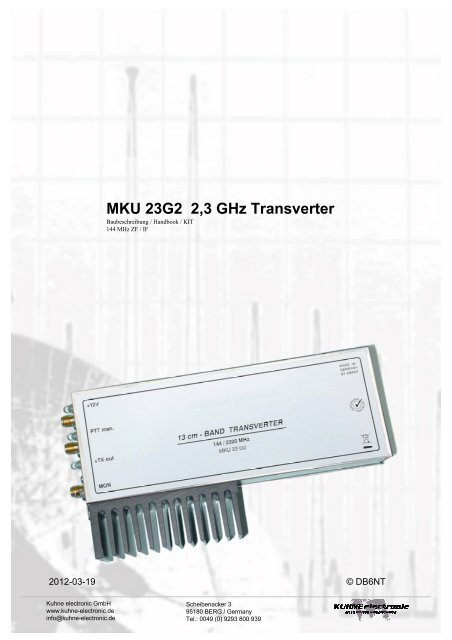
MKU 23G2 2,3 <strong>GHz</strong> <strong>Transverter</strong><br />
Baubeschreibung / Handbook / KIT<br />
144 MHz ZF / IF<br />
2012-03-19 © DB6NT
<strong>Kuhne</strong> <strong>electronic</strong> GmbH<br />
www.kuhne-<strong>electronic</strong>.de<br />
info@kuhne-<strong>electronic</strong>.de<br />
2,3 <strong>GHz</strong> <strong>Transverter</strong> <strong>MKU23G2</strong><br />
Sicherheitshinweise – für Fertigmodule, Bausätze und<br />
Bauteile<br />
Achtung: Verletzungsgefahr!<br />
Weißblech / Neusilbergehäuse / Kühlkörper sind sehr<br />
scharfkantig. Bitte vorsichtig damit umgehen. Darf nicht in die<br />
Hände von Kindern gelangen. Vorsicht bei Deckelmontage,<br />
Quetschungsgefahr der Finger und Schnittgefahr.<br />
Benutzung der Baugruppen, Montage der Bausätze darf nur<br />
durch autorisiertes Fachpersonal oder lizenzierte<br />
Funkamateure erfolgen.<br />
Bausätze / Fertigmodule enthalten Kleinteile, dürfen nicht in die<br />
Hände von Kindern und unbefugten Personen gelangen.<br />
Verletzungsgefahr! Verschluckungsgefahr von Kleinteilen.<br />
Teile dürfen nicht in den Mund genommen werden!<br />
Elektronikbaugruppen dürfen nur innerhalb der Spezifikation<br />
betrieben werden. Maximale Versorgungsspannung darf nicht<br />
überschritten werden!<br />
Verpackungsmaterial (Plastiktüten, Styropor usw.) und<br />
Kleinteile dürfen nicht in die Hände von Kindern gelangen.<br />
Erstickungs- und Verschluckungsgefahr, kein Spielzeug!<br />
Die Anleitung / das Messprotokoll bitte für späteren Gebrauch<br />
aufbewahren.<br />
Entsorgen Sie die Module / Bauteile nur bei den<br />
vorhergesehenen Sammelstellen.<br />
Für den Betrieb von Sende- und Empfangsanlagen sind die<br />
gesetzlichen Vorschriften zu beachten.<br />
Zum Aufbau des <strong>Transverter</strong>s sind Erfahrungen mit SMD-<br />
Bauteilen und deren Verarbeitung zwingend notwendig. Es<br />
sollte in keinem Fall das „SMD-Erstlingswerk“ werden, da<br />
Bauteile mit sehr kleiner Bauform zu verarbeiten sind.<br />
Ferner sollten Grundkenntnisse beim Aufbau von UKW<br />
Schaltungen vorhanden sein.<br />
Verschiedene Komponenten wie FET’s sind statisch sehr<br />
empfindlich.<br />
ESD (Electrostatic Sensitive Device) Schutzmaßnahmen beim<br />
Aufbau sind unbedingt einzuhalten.<br />
Literatur:<br />
1. „<strong>Transverter</strong> for 2,3 <strong>GHz</strong> by DB6NT“ DUBUS 3.93<br />
(DUBUS Buch IV)<br />
2. Download dieser Beschreibung:<br />
http://www.kuhne-<strong>electronic</strong>.de<br />
Bezug der Bausätze:<br />
KUHNE <strong>electronic</strong> GmbH<br />
Scheibenacker 3<br />
D-95180 BERG<br />
Tel.: 0049 (0) 9293 800 939<br />
Fax: 0049 (0) 9293 800 938<br />
Email: info@kuhne-<strong>electronic</strong>.de<br />
Alle Rechte beim Autor DB 6 NT Michael <strong>Kuhne</strong><br />
KUHNE <strong>electronic</strong> GmbH<br />
Scheibenacker 3<br />
95180 BERG / Germany<br />
Tel.: 0049 (0) 9293 800 939<br />
2012-03-19<br />
Safety instructions – for readymade modules, KIT’s and<br />
units<br />
Caution: Risk of injury!<br />
Tin plate / German Silver / cases / heat sink are very sharpedged.<br />
Please handle with care. It should not get into the<br />
hands of children. Be careful when assembling the top cover,<br />
danger of contusion and cutting.<br />
Using of the components and assembling the kits should only<br />
be done by authorized and qualified personnel or licensed radio<br />
amateurs.<br />
KIT’s / readymade modules contain small parts, and should not<br />
get into the hands of children or unauthorized persons. Risk of<br />
injury! Danger of swallowing small parts. The parts should not<br />
be taken into the mouth!<br />
Electronic components are only to be run within the<br />
specifications. Maximum supply voltage should not be<br />
exceeded!<br />
Keep packing material (plastic bags, polystyrene etc.) and<br />
small parts out of the reach of children. Danger of suffocation<br />
and swallowing – no toys!<br />
Please keep the manual / measuring report for future use.<br />
Dispose the modules / components only at collection points<br />
which are designated for it.<br />
For operating the high frequency modules the legal instructions<br />
have to be considered.<br />
To achieve a successful construction of this transverter the<br />
builder has to have experiences in the use and handling of<br />
SMD-parts.<br />
Furthermore experiences with smaller projects in microwave<br />
circuits are valuable.<br />
In any case the construction of this <strong>Transverter</strong> is not a<br />
beginners project.<br />
Caution ESD (Electrostatic Sensitive Device) Do not open<br />
except at approved field force protective workstation<br />
Literature:<br />
1. “<strong>Transverter</strong> for 2.3 <strong>GHz</strong> by DB6NT”, DUBUS 3/93<br />
(Dubus book IV respectively)<br />
2. Download of the KIT description:<br />
http://www.kuhne-<strong>electronic</strong>.de<br />
Purchase KIT’s:<br />
KUHNE <strong>electronic</strong> GmbH<br />
Scheibenacker 3<br />
D-95180 BERG<br />
Tel.: 0049 (0) 9293 800 939<br />
Fax: 0049 (0) 9293 800 938<br />
Email: info@kuhne-<strong>electronic</strong>.de<br />
All rights reserved to the author DB 6 NT Michael <strong>Kuhne</strong><br />
KUHNE <strong>electronic</strong> GmbH
Einführung<br />
<strong>Kuhne</strong> <strong>electronic</strong> GmbH<br />
www.kuhne-<strong>electronic</strong>.de<br />
info@kuhne-<strong>electronic</strong>.de<br />
2,3 <strong>GHz</strong> <strong>Transverter</strong> <strong>MKU23G2</strong><br />
Der hier beschriebene <strong>Transverter</strong> ist eine Weiterentwicklung<br />
der 1993 veröffentlichten Schaltung. Die Baugruppe konnte<br />
durch die Verwendung moderner Halbleiterbauteile in ihren<br />
technischen Daten weiter verbessert werden. Durch<br />
Überarbeiten des Leiterplattendesign hinsichtlich der Kühlung<br />
der Leistungsbauteile konnte eine weitere Verbesserung des<br />
<strong>Transverter</strong>s erreicht, sowie die Nachbaubarkeit vereinfacht<br />
werden.<br />
Die Schaltung ist auf Keramik gefülltem Epoxid Substrat<br />
aufgebaut. Das Empfangsteil erreicht eine Rauschzahl von<br />
kleiner 0,8 dB NF, bei mehr als 20 dB Verstärkung. Somit ist<br />
auch ein externer Empfangsvorverstärker nicht mehr<br />
erforderlich.<br />
Das Sendeteil erzeugt eine Ausgangsleistung von > 1 W, bei<br />
typisch -60 dB Nebenwellen- und -30 dB Oberwellen-<br />
Unterdrückung.<br />
Der <strong>Transverter</strong> ist für die lineare Umsetzung des 2 Meter-<br />
Bandes in das 13 cm Amateurband Schmalbandbereich 2320<br />
Q 2322 MHz konstruiert, durch kleine Änderungen ist der<br />
<strong>Transverter</strong> auch auf die OSCAR P3D Frequenz 2400 Q 2402<br />
MHz abstimmbar. Der 2 Meter Steuerleistungsbereich ist von<br />
0,5 Q 3 Watt einstellbar, durch Änderung eines Widerstandes<br />
sind auch 10 mW ausreichend. Die Steuerleistung sollte nicht<br />
zu groß gewählt werden um eine unnötige Erwärmung der<br />
Baugruppe durch die ZF-Verlust-Leistung zu vermeiden.<br />
Der gesamte <strong>Transverter</strong> mit ZF-Umschaltung, Steuerausgang<br />
für Koaxrelais oder PA’s, Quarzoszillator und LO-Aufbereitung<br />
ist in einem Weißblechgehäuse mit den Abmessungen 60 x<br />
150 x 30 mm untergebracht.<br />
Ein Abgleich durch aufwendige HF-Messtechnik entfällt, es ist<br />
lediglich ein Spannungs-Messgerät erforderlich.<br />
Mein besonderer Dank gilt Lorenz, DL6NCI, der durch seine<br />
„Aufbau“-Erfahrung und zahlreichen Anregungen entscheidend<br />
zur Serienreife des <strong>Transverter</strong>s beitrug. Ferner bedanke ich<br />
mich bei Richard, DF5SL, Gert, DG8EB, und Jürgen, DC0DA,<br />
die durch „Nachbauten“ die Reproduzierbarkeit der Schaltung<br />
bestätigten.<br />
Introduction<br />
Scheibenacker 3<br />
95180 BERG / Germany<br />
Tel.: 0049 (0) 9293 800 939<br />
2012-03-19<br />
This transverter is a further development of the schematic<br />
published in 1993. Technical data of the assembly were further<br />
improved by the application of modern semiconductor devices.<br />
Redesign of the printed circuit board in respect to cooling of the<br />
high power devices improves the general performance of the<br />
transverter; its duplication has been further simplified.<br />
The circuitry has been laid out on a ceramic-filled epoxy<br />
substrate. The receiver section achieves a noise figure (NF) of<br />
less than 0.8 dB at an amplification of more than 20 dB. This<br />
eliminates the need for an external preamplifier.<br />
The transmitter section produces an output power of > 1 W;<br />
suppression of spurious emissions is –60 dB (typ.) while<br />
harmonics are being suppressed by –30 dB (typ.).<br />
The transverter has been designed for the linear transfer of the<br />
2 m band to the narrow band amateur section of the 13 cm<br />
band (2320 Q 2322 MHz); by some small modifications it may<br />
be tuned for the Oscar P3D frequency of 2400 Q 2402 MHz. 2<br />
meter driving power can be adjusted from 0.5 Q 3 Watts; a<br />
change of a resistor will even allow a driving power of 10 mW.<br />
Driving power should not be too high; this avoids unnecessary<br />
heating of the IF-subassembly due to power dissipation.<br />
The entire transverter fits into a tinplate case measuring 60 x<br />
150 x 30 mm. This includes IF switching, output control for<br />
coax-relays or final amplifier, crystal oscillator and local<br />
oscillator circuitry. No elaborate RF measuring equipment is<br />
needed for its alignment; a simple voltage measuring<br />
instrument will do.<br />
My special thanks to Lorenz, DL6NCI. His support and the<br />
discussions were mandatory for the success of this<br />
development. Also my thanks to Richard, DF5SL, to Gert,<br />
DG8EB, and to Jürgen, DC0DA, who verified the reproducibility<br />
of the design by building this transverter.
Schaltungsbeschreibung:<br />
<strong>Kuhne</strong> <strong>electronic</strong> GmbH<br />
www.kuhne-<strong>electronic</strong>.de<br />
info@kuhne-<strong>electronic</strong>.de<br />
2,3 <strong>GHz</strong> <strong>Transverter</strong> <strong>MKU23G2</strong><br />
Der bewährte „Simple Quarzoszillator“ mit dem FET SST310<br />
schwingt auf 120,889 MHz. Die Frequenzeinstellung erfolgt<br />
durch den Messingkern in der Oszillatorspule. Ein auf das 40<br />
°C Quarz aufgesteckter Heizer stabilisiert die Quarztemperatur<br />
und hält somit die Frequenzdrift in Grenzen. Durch Einbau<br />
entsprechender Kondensatoren (TK. Im Schaltplan mit *<br />
gekennzeichnet) wird im Oszillator eine Temperatur-<br />
Kompensation erreicht. Dafür sind 2 Lötstellen vorgesehen.<br />
Die Stabilität reicht für normale Verhältnisse aus.<br />
Sollte eine sehr genaue und hochstabile Frequenz benötigt<br />
werden, ist an der im Schaltplan eingezeichneten Stelle ein<br />
externer „Ofenstabilisierter“ Oszillator „OCXO“ mit ca. 1 mW<br />
(DF9LN) ein zu koppeln. Dazu wird der Quarz entfernt.<br />
Nach dem Oszillator folgt eine Verdreifacher-Stufe mit dem<br />
BFR92. Über ein Helixfilter wird die Frequenz 362 MHz<br />
selektiert und auf den Verdreifacher mit BFG 93A gekoppelt.<br />
Nach einem weiteren Helixfilter, das auf 1088 MHz abgestimmt<br />
wird, gelangt das Signal auf einen Frequenzverdoppler. Nach<br />
dem Helixfilter auf der LO- Endfrequenz 2176 MHz steht eine<br />
LO-Leistung von ca. 5 mW zu Verfügung.<br />
Das ZF-Signal wird über getrennt einstellbare<br />
Dämpfungsglieder für Sender und Empfänger geführt, die<br />
durch PIN-Dioden umgeschaltet werden.<br />
Die Sende-Empfangs-Umschaltung des gesamten<br />
<strong>Transverter</strong>s erfolgt über eine Plusspannung bei TX auf dem<br />
ZF-Steuerkabel, wie es bei dem FT290R bereits eingebaut ist.<br />
Bei anderen Transceivern ist ein kleiner Umbau erforderlich<br />
(Eine bei Senden verwendete +Spannung im 2 m Transceiver,<br />
über einen 2K2 Widerstand auf die Ausgangsbuchse legen.<br />
Fertig!). Diese Steuerung benötigt keine weiteren Steuerkabel<br />
und hat sich seit Jahren bestens bewährt. Des weiteren ist<br />
aber auch die klassische Umschaltung mit PTT-Kontakt nach<br />
Masse möglich.<br />
Die Betriebsspannungsumschaltung im <strong>Transverter</strong> erfolgt<br />
durch Transistoren. Die Schaltspannung des Senders ist<br />
herausgeführt und kann zur Steuerung von Koaxrelais sowie<br />
PA-Verstärkern verwendet werden (max. 2 A belastbar). Dieser<br />
Ausgang sollte unbedingt mit einer Feinsicherung geschützt<br />
werden.<br />
Das Empfangsteil besitzt eine HEMT-FET Vorstufe und einen<br />
weiteren MMIC mit einer Gesamtverstärkung von > 30 dB.<br />
Dadurch wird kein weiterer ZF-Verstärker benötigt.<br />
Das über einen 4,7 pF Kondensator gekoppelte<br />
Eingangssignal wird dem rauschangepassten NE32584C<br />
zugeführt. Danach folgt über ein Multilayer-Keramikfilter F6 die<br />
zweite Stufe mit dem MMIC - MGA86563. Über die RX-TX<br />
PIN-Diodenumschaltung und ein weiteres Helixfilter F4 folgt<br />
der Ringmischer.<br />
Über das auch für den Sendezweig benützte Helixfilter F4<br />
hinter dem Mischer, gelangt im Sendefall das TX-Signal auf<br />
eine MMIC Verstärkerstufe. Über ein weiteres Helixfilter F5 zur<br />
Nebenwellenunterdrückung wird das zweite MMIC ERA 5-SM<br />
angesteuert. Die darauf folgende Endstufe ist mit dem GaAs<br />
Power FET MGF 0904 bestückt.<br />
Zur Nebenwellenunterdrückung werden Helixfilter verwendet.<br />
Am Senderausgang ist ein Richtkoppler mit Schottkydiode<br />
BAT62-03W eingebaut. Er ermöglicht die Kontrolle der<br />
Ausgangsleistung (Monitor = MON.) und erleichtert den<br />
Abgleich der Schaltung.<br />
Description:<br />
Scheibenacker 3<br />
95180 BERG / Germany<br />
Tel.: 0049 (0) 9293 800 939<br />
2012-03-19<br />
The well proven “Simple Quartz Oscillator” with its FET<br />
SST310 operates at 120.889 MHz. Frequency tuning is<br />
achieved by the brass slug in the oscillator coil. A heater which<br />
is mounted on a 40 °C thermostat crystal stabilizes the crystal<br />
temperature and keeps the frequency drift in limits. Application<br />
of relevant capacitors (TK. Marked with * in the schematic) will<br />
result a temperature compensation. Two capacitor soldering<br />
points have been provided for this feature. Stability should be<br />
sufficient for average working conditions. Should there be the<br />
need for an exact and highly stable frequency, an ovencontrolled<br />
oscillator (DF9LN) with an output of approx. 1 mW<br />
may be connected to the circuitry at the marked location. For<br />
this change the original crystal must be removed.<br />
Following the oscillator is a tripler with a BFR92. A frequency of<br />
362 MHz is being selected by a helix filter and then is being<br />
coupled into a tripler with a BFG93A. After an additional helix<br />
filter, which is to be tuned to 1088 MHz, the signal is being<br />
passed to a frequency doubler. After a helix filter with a final<br />
local oscillator (LO) frequency of 2176 MHz a LO-power of 5<br />
mW is available.<br />
The IF signal is being passed through individually tunable<br />
attenuator pads for transmitter and receiver; switching occurs<br />
by PIN-diodes.<br />
Transmit/receive switching of the entire transverter is being<br />
controlled by a positive voltage during TX of the IF control<br />
cable; e.g. such a voltage is available at the output of the<br />
FT290R. Other transceivers need a small modification: connect<br />
a positive voltage, that is being generated within the transceiver<br />
during transmit mode, to the output connector via a 2K2<br />
resistor. That’s all! This type of control needs no additional<br />
control cables and has been well proven over the years.<br />
Naturally it is also possible to achieve conventional switchover<br />
with a PTT contact to ground.<br />
Switching of operating voltages within the transverter is being<br />
controlled by transistors. Switching voltage of the transmitter is<br />
being externally provided and may be used for the control of<br />
coax-relays or final amplifiers (max. load 2 A). This output<br />
must be protected by a fine-wire fuse under all circumstances.<br />
The receiving section has a preamplifier stage with a HEMT-<br />
FET and an additional MMIC with a total amplification of > 30<br />
dB. This eliminates the need for an additional IF-amplifier.<br />
The input signal is being coupled to a noise-adapted<br />
NE32584C via a 4.7 pF capacitor.<br />
The second stage with the MMIC - MGA86563 follows via the<br />
multi-layer ceramic filter F6. A RX-TX PIN diode switch is being<br />
followed by another helix filter F4 and the ring mixer.<br />
During transmit the TX-signal is being passed to a MMIC<br />
amplifier stage via the helix filter F4 following the mixer. The<br />
signal reaches a second MMIC ERA 5-SM after passing an<br />
additional helix filter F5 used for suppression of spurious<br />
emissions. The following final stage is equipped with a GaAs<br />
power FET MGF 0904.<br />
The transmitter output has a directional coupler with the<br />
Schottky-diode BAT62-03W. It facilitates monitoring of the<br />
output power (monitoring MON.) and supports the alignment of<br />
the circuitry.
Aufbaureihenfolge:<br />
<strong>Kuhne</strong> <strong>electronic</strong> GmbH<br />
www.kuhne-<strong>electronic</strong>.de<br />
info@kuhne-<strong>electronic</strong>.de<br />
2,3 <strong>GHz</strong> <strong>Transverter</strong> <strong>MKU23G2</strong><br />
a. Anpassen der Leiterplatten an das Weißblechgehäuse<br />
durch anfeilen der Ecken.<br />
b. Anzeichnen der Löcher am Blechgehäuse für die SMA-<br />
Koaxialbuchsen.<br />
c. Bohren der Löcher für Buchsen und<br />
Durchführungskondensatoren. M2 Gewinde für SMA-<br />
Buchsen. Kürzen der SMA-Buchsen-Anschlüsse auf ca.<br />
2,3 mm Länge. Montage der SMA-Buchsen<br />
d. Einlöten der Leiterplatte in das Gehäuse (siehe<br />
Zeichnung). Rundherum verlöten! Um einen<br />
gleichmäßigen Abstand der Leiterplatte beim Einlöten zu<br />
erreichen, hat sich ein 10,2 mm starkes Holzstück als<br />
Unterlage bewährt.<br />
e. Bestücken der Leiterplatte und<br />
Durchführungskondensatoren. Verlöten der Helixfilter,<br />
siehe Bestückplan. Der Festspannungsregler L4940V10<br />
wird mit dem Kühlflansch am Weißblechgehäuse verlötet.<br />
Dabei ist das mittlere Anschlussbeinchen abzubrechen.<br />
Der FET BUZ171 / 08P06P wird voll auf die Leiterplatte<br />
gedrückt und dann an den Beinchen verlötet, da sonst der<br />
Kühlflansch den Deckel berühren würde<br />
(Kurzschlussgefahr). Danach wird die Baugruppe in<br />
Alkohol (Spiritus) gewaschen.<br />
Sollte ein Ultraschall-Waschbad verwendet werden, ist der<br />
Quarz erst danach einzulöten (Quarze werden durch<br />
starken Ultraschall beschädigt). Trocknen bei ca. 80 °C im<br />
Ofen (1Std.), oder über Nacht auf einem warmen<br />
Heizkörper.<br />
f. Einlegen des Kühlblockes in das Gehäuse und Anzeichnen<br />
der zu Bohrenden 2 Löcher, die zur Befestigung mit dem<br />
Rippenkühlkörper dienen (Bohrer ca. 3,5 Q 4mm,<br />
entgraten!). Vor dem Zusammenschrauben sollte etwas<br />
Wärmeleitpaste zwischen Kühlblock, Seitenwand und<br />
Kühlkörper gegeben werden. Die Montage mit den M3 x 25<br />
mm Innensechskantschrauben sowie den 4 Stück M2 x 4<br />
mm um den Endstufentransistor sollte wechselseitig<br />
erfolgen, dabei ist ein Luftspalt zwischen Leiterplatte und<br />
Kühlblock zu vermeiden.<br />
Die Montage des Endtransistors erfolgt ebenfalls mit etwas<br />
Wärmeleitpaste.<br />
Info:<br />
Zur Abstimmung ist unbedingt ein Schraubenzieher mit<br />
passender Schlitzgröße zu verwenden, da sonst Bruchgefahr<br />
für den Ferrit- bzw. die Keramikkerne besteht! Die<br />
Keramikschrauben verursachen bei sehr häufiger Betätigung<br />
Metallabrieb auf ihrer Oberfläche. Erkennbar durch „ruppiges“<br />
Abstimmverhalten. Der Belag kann mit Glasfaserstift entfernt<br />
werden.<br />
Scheibenacker 3<br />
95180 BERG / Germany<br />
Tel.: 0049 (0) 9293 800 939<br />
Construction Steps:<br />
2012-03-19<br />
a. Fitting of the printed circuit boards into the tinplate case by<br />
filing down the corners.<br />
b. Marking of the holes on the box for insertion of the SMAcoax<br />
connectors.<br />
c. Drilling of holes for connectors and feed-through<br />
capacitors. Tapping for M2 screws of the SMAconnectors.<br />
Shortening of SMA-connector pins to approx.<br />
2.3 mm length. Mounting of SMA-connectors.<br />
d. Soldering of printed circuit boards into the case (see<br />
drawing). Solder all the way around! A 10.2 mm<br />
thick wooden board should be used as a support to<br />
achieve uniform positioning of the printed circuit board.<br />
e. Applying component parts and insertion of feed-through<br />
capacitors. Consult the component layout plan for<br />
soldering the helical filters. The cooling flange of the<br />
constant voltage regulator L4940V10 must be<br />
soldered to the tinplate case; its middle pin<br />
should be broken off. The FET BUZ 171 / 08P06P should<br />
be pressed all the way down onto the printed circuit<br />
board and its pins then be soldered. Otherwise there<br />
could be the possibility of the cooling flange<br />
causing a short at the lid of the case. 0.5 mm soldering<br />
wire should be used for the SMD components.<br />
After completion of the soldering the module should be<br />
washed in alcohol.<br />
Should an ultrasound cleaning device be used, the crystal<br />
should be soldered into the circuitry after completion of the<br />
cleansing. (Crystals may be damaged by intense<br />
ultrasound.) Drying at 80 °C for one hour in an oven or<br />
overnight on a heater.<br />
f. Insertion of the cooling block into the case and marking of<br />
the 2 holes that will later be used to hold the finned<br />
cooling block (drill diameter approx. 3.5 Q 4 mm;<br />
smoothen the edges). Before bolting together,<br />
some heat conducting paste should be applied between<br />
cooling block, the wall of the case and the finned cooling<br />
block. Mounting the M3 x 25 mm hex screws as well as<br />
the four M2 x 4 mm screws around the final transistor<br />
should be done alternatively; any air gap between printed<br />
circuit board and the cooling block must be avoided.<br />
Some Heat conducting paste should also be used<br />
when mounting the final transistor.<br />
Info:<br />
To avoid the risk of breakage of the ferrite / ceramic cores a<br />
screw driver with adequate size must be used for tuning. In<br />
cases of frequently use the ceramic screws cause metal<br />
abrasion of the surface. This can be noticed by a rough tuning<br />
behaviour. The coating can be removed with a fibre glass pin.
Abgleich:<br />
<strong>Kuhne</strong> <strong>electronic</strong> GmbH<br />
www.kuhne-<strong>electronic</strong>.de<br />
info@kuhne-<strong>electronic</strong>.de<br />
2,3 <strong>GHz</strong> <strong>Transverter</strong> <strong>MKU23G2</strong><br />
a. Anlegen der +12 V Betriebsspannung von einem Netzgerät<br />
mit Strombegrenzung ca. 1 A. Kontrolle der<br />
Betriebsspannungen an den Festspannungsreglern.<br />
b. Messen der Kollektorspannung des BFR92 Verdopplers<br />
am Messpunkt 1. Eindrehen des Messingkerns in die<br />
Oszillatorspule Papierstreifen als „Kernbremse“ beilegen!<br />
Beim Anschwingen des Oszillators geht die Spannung auf<br />
ca. 7,2 V zurück.<br />
c. Messen der Spannung am Messpunkt 2. Durch<br />
wechselseitiges Abstimmen des 362 MHz Bandfilters -F1wird<br />
auf minimale Spannung abgeglichen, ca. 6,2 V<br />
(maximaler Strom = optimale Ansteuerung).<br />
d. Messen der Spannung am Messpunkt 3. Durch<br />
wechselseitiges Abstimmen des 1088 MHz Bandfilters -F2wird<br />
auf minimale Spannung abgeglichen, ca. 6,6 V<br />
(maximaler Strom = optimale Ansteuerung).<br />
e. Eindrehen der Messing-Abstimmschrauben nach den im<br />
Bestückplan eingezeichneten Maßen (Filter F3, F4 und<br />
F5).<br />
f. Anschließen eines geeigneten Abschlusswiderstandes an<br />
die Antennenbuchse des Empfangsteiles. Messen der<br />
Spannung am Drainanschluß des NE32584C<br />
Vorstufentransistors und Einstellen von ca. 2 V durch das<br />
10K Potentiometer am Gate der FET’s.<br />
g. Anschließen eines 2 m Empfängers am ZF-Ausgang in<br />
Stellung SSB. RX- und TX-Gain-Potentiometer sind dabei<br />
auf Linksanschlag zu drehen (max. Verstärkung).<br />
Jetzt sollte ein Rauschanstieg im 2 m Empfänger zu hören<br />
sein. Durch wechselseitiges Abstimmen des Helixfilter´s F4<br />
sollte auf maximales Rauschen und somit<br />
Empfangsverstärkung abgeglichen werden. Danach erfolgt<br />
der Abgleich des LO- Filters F 3.Ist am 2 Meter<br />
Transceiver ein S-Meterausschlag von mehr als S1 zu<br />
erkennen, kann die Verstärkung des <strong>Transverter</strong>s mit dem<br />
RX-Gain Regler entsprechend angepasst werden.<br />
Somit ist der Abgleich des Empfangsteils abgeschlossen.<br />
h. Anschließen des Senderausgangs an einen<br />
Abschlusswiderstand. <strong>Transverter</strong> auf Stellung „Senden“<br />
schalten. Einstellen des Ruhestroms der Endstufe auf ca.<br />
220 mA oder 9,5 V am Drain des Transistors.<br />
Ansteuerung durch ein 2 m Sendesignal mit 0,5...3 Watt.<br />
Messen der Monitorspannung am Richtkoppler.<br />
Es ist eine Gleichspannung zu messen. Diese Spannung<br />
ist der Ausgangsleistung entsprechend proportional. Jetzt<br />
folgt der Abgleich des Helixfilters F5 auf max. Monitor-<br />
Spannung = Ausgangsleistung. Zurückregeln der<br />
Monitorspannung auf ca. 1 Volt durch das Rechtsdrehen<br />
des TX-Gain Potentiometers. Jetzt erfolgt der Feinabgleich<br />
des Helixkreises -F5- (2320 MHz) und des LO-Filters -F3-<br />
(2176 MHz) auf maximale Ausgangsleistung.<br />
i. Einpegeln der Sendeleistung durch Drehen des TX-Gain<br />
Potis. Dabei ist die Monitorspannung zu messen. Es<br />
empfiehlt sich die Ausgangsleistung auf ca. 80 % des<br />
Maximalwertes einzustellen, um somit im linearen<br />
Arbeitsbereich des <strong>Transverter</strong>s zu bleiben.<br />
Alignment:<br />
Scheibenacker 3<br />
95180 BERG / Germany<br />
Tel.: 0049 (0) 9293 800 939<br />
2012-03-19<br />
a. Applying of +12 V operating voltage by using a power<br />
supply with a 1 A (approx.) current limiter. Verifying of<br />
operating voltages at the constant voltage regulators.<br />
b. Measuring of the collector voltage of the BFR92 doubler at<br />
test point 1. Screw the brass slug into the oscillator coil -<br />
use a paper strip for “slug friction”! When oscillation<br />
occurs the voltage should drop to approx. 7.2 V.<br />
c. Measuring of the voltage at test point 2. By alternatively<br />
tuning the 362 MHz band filter -F1-, a minimum voltage of<br />
approx. 6.2 V should be achieved (max. current =<br />
Optimum drive).<br />
d. Measuring of the voltage at test point 3. By alternatively<br />
tuning the 1088 MHz band filter -F2-, a minimum voltage<br />
of 6.6 V should be achieved (max. current = optimum<br />
drive).<br />
e. Screw in the brass tuning slugs according to the<br />
measurements given in the parts layout plan (Filter F3, F4<br />
and F5).<br />
f. Connect a suitable antenna or a dummy load to the<br />
antenna connector of the receiver section. Measuring of<br />
the voltage at the drain of preamp transistor NE32584C<br />
and adjustment to approx. 2 V by the 10K potentiometer at<br />
the gate of the FET’s.<br />
g. Connect a 2 m receiver in SSB mode to the IF output.<br />
Potentiometers for RX- and TX-gain should be in the full<br />
counter-clockwise position (max. amplification). An<br />
increase in noise level should be heard in the 2 m<br />
receiver. Maximum noise and thereby maximum receiver<br />
amplification should be achieved by alternative tuning of<br />
helix filter F4. Afterwards LO-filter F3 should be adjusted.<br />
If the S-meter of the 2 m transceiver shows more than S1,<br />
the amplification of the transverter may be adjusted with<br />
the RX-gain control.<br />
This terminates tuning of the receiver section.<br />
h. Connect a suitable antenna or a dummy load to the<br />
transmitter output. Switch transverter to position “Senden”<br />
(= transmit). Adjustment of the idling current of the final<br />
amplifier to 220 mA or 9.5 V at the drain of the transistor.<br />
Apply a 2 m driving power of 0.5 Q 3 Watts.<br />
Measuring of the monitor voltage at the directional<br />
coupler. This is a DC-voltage measurement which is<br />
directly proportional to the output power.<br />
Now helix filter F5 should be adjusted to maximum<br />
monitor voltage (= output power). Reduction of monitor<br />
voltage to approx. 1 volt by turning TX-gain potentiometer<br />
clockwise. Maximum output power should be tuned by<br />
fine tuning helix circuit -F5- (2320 MHz) and LO-filter –F3-<br />
(2176 MHz).<br />
i. Adjustment of transmitting power by tuning the TX-gain<br />
potentiometer while monitoring the voltage of the<br />
directional coupler. In order to assure operation within the<br />
linear portion of the transverter, output power should be<br />
adjusted to 80 % of the maximum value.
<strong>Kuhne</strong> <strong>electronic</strong> GmbH<br />
www.kuhne-<strong>electronic</strong>.de<br />
info@kuhne-<strong>electronic</strong>.de<br />
2,3 <strong>GHz</strong> <strong>Transverter</strong> <strong>MKU23G2</strong><br />
j. Anschließen einer Antenne. Einstellen der Oszillator-<br />
Frequenz mittels einer Bake mit bekannter Sendefrequenz.<br />
Sollte sich die genaue Frequenz nicht einstellen lassen, ist<br />
eine Drossel mit 0,22 µH parallel zum Quarz einzulöten.<br />
k. Einbau der Baugruppe in ein Gehäuse, wobei der<br />
<strong>Transverter</strong> zur besseren Kühlung auf das Chassisblech<br />
montiert werden sollte. Dafür sind im Kühlkörper<br />
entsprechende Gewindebohrungen vorgesehen. Eine gute<br />
Kühlung verhindert auch eine Frequenzdrift des<br />
Quarzoszillators. Ein geeignetes Koaxrelais dient zur<br />
Sende-Empfangsumschaltung.<br />
Scheibenacker 3<br />
95180 BERG / Germany<br />
Tel.: 0049 (0) 9293 800 939<br />
2012-03-19<br />
j. Connect a receiving antenna. Adjustment of oscillator<br />
frequency by tuning to a known beacon. Should it not be<br />
possible to tune to the desired frequency, a choke of 0.22<br />
µH can be soldered in parallel to the crystal.<br />
k. Install the entire transverter into an enclosure. For better<br />
cooling, the transverter should be mounted onto the<br />
chassis. Specially tapped holes have been provided in the<br />
cooling block. A good cooling also prevents frequency<br />
drifting of the oscillator. A suitable coax relay facilitates<br />
transmit-receive switching.
<strong>Kuhne</strong> <strong>electronic</strong> GmbH<br />
www.kuhne-<strong>electronic</strong>.de<br />
info@kuhne-<strong>electronic</strong>.de<br />
2,3 <strong>GHz</strong> <strong>Transverter</strong> <strong>MKU23G2</strong><br />
Sende-Empfangsumschaltung der DB6NT-<strong>Transverter</strong>:<br />
Um einen DB6NT-Mikrowellentransverter von Empfang (RX)<br />
auf Senden (TX) umzuschalten, sind zwei Möglichkeiten<br />
vorgesehen.<br />
Zum einen besitzen die <strong>Transverter</strong> einen PTT-Anschluss, der<br />
bei Sendebetrieb über einen Kontakt nach Masse zu schalten<br />
ist.<br />
Des Weiteren ist eine Umschaltmöglichkeit über das ZF-Kabel<br />
vorgesehen. Dazu ist im Sendefall eine Spannung zwischen<br />
+3 ... 12 V auf den Innenleiter der ZF-Buchse zu schalten. Dies<br />
erspart eine zusätzliche Verbindungsleitung zwischen<br />
<strong>Transverter</strong> und Transceiver.<br />
Bei den Transceivern YAESU FT-290R (altes Modell) und<br />
ICOM IC-402 ist eine geeignete Umschaltsteuerung bereits<br />
eingebaut.<br />
Im YAESU FT-290RII muss diese Schaltung nachträglich<br />
eingebaut werden. Eine Bauanleitung wurde von Sam,<br />
G4DDK, beschrieben. Sie ist auf seiner Homepage abrufbar<br />
unter www.btinternet.com/~jewell<br />
Bei dem Transceiver ICOM IC-202 ist die benötigte Steuerung<br />
invers eingebaut. Bei Empfang werden +12 V am Ausgang<br />
geliefert. Das heißt, wenn der Transceiver auf Empfang ist und<br />
an einen <strong>Transverter</strong> angeschlossen wird, dann schaltet dieser<br />
auf Senden! Daher ist eine kleine Änderung im IC-202<br />
notwendig (siehe Bild unten).<br />
Für den <strong>Transverter</strong>betrieb mit dem YAESU FT-817 hat Peter<br />
Vogl, DL1RQ eine Umbauanleitung verfasst. Sie ist im Internet<br />
unter www.bergtag.de/technik_18.html abrufbar.<br />
Eine weitere Umbaubeschreibung für den YAESU FT-817 gibt<br />
es von Pedro M.J. Wyns, ON7WP. Sie kann auf unserer<br />
Homepage unter www.kuhne-<strong>electronic</strong>.de/de/154_AN005/<br />
nachgelesen werden.<br />
Umbau der Sende-Empfangsumschaltung im IC-202<br />
Modification of RX-TX switching in the ICOM IC-202<br />
Scheibenacker 3<br />
95180 BERG / Germany<br />
Tel.: 0049 (0) 9293 800 939<br />
2012-03-19<br />
RX-TX switching of DB6NT <strong>Transverter</strong>s:<br />
To switch a DB6NT microwave transverter from receive (RX) to<br />
transmit (TX), there are two possibilities.<br />
The first: switch the port "PTT" of the transverter to ground for<br />
TX.<br />
The second: supply +3 Q 12 V DC to the core (center<br />
conductor) of the IF cable for TX.<br />
This (second) method saves an additional PTT cable between<br />
transverter and transceiver.<br />
A suitable control circuit is already included in the transceivers<br />
YAESU FT-290R (old model) and ICOM IC-402.<br />
They provide +12 V DC on the coaxial output connector (core)<br />
at TX.<br />
The YAESU FT-290RII (new model) does not provide this<br />
function, but it can be modified. The modification is described<br />
on G4DDK's homepage: www.btinternet.com/~jewell<br />
ATTENTION! The ICOM IC-202 provides +12 V at RX! So<br />
when you connect a DB6NT transverter to a IC-202, then the<br />
transverter will switch to TX. Therefore, a small modification is<br />
necessary (see picture below). With this modification the IC-<br />
202 will provide +12 V at TX.<br />
The YAESU FT-817 must also be modified for transverter<br />
operation. Peter Vogl, DL1RQ, has written a small tutorial, how<br />
to do this modification:<br />
www.bergtag.de/technik_18.html<br />
A further description for the YAESU FT-817 is written by Pedro<br />
M.J. Wyns, ON7WP. This description is published on our<br />
website:<br />
www.kuhne-<strong>electronic</strong>.de/de/154_AN005/
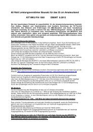
Präzisions-Quarzheizer QH40A:<br />
<strong>Kuhne</strong> <strong>electronic</strong> GmbH<br />
www.kuhne-<strong>electronic</strong>.de<br />
info@kuhne-<strong>electronic</strong>.de<br />
2,3 <strong>GHz</strong> <strong>Transverter</strong> <strong>MKU23G2</strong><br />
Dieser Präzisionsquarzheizer dient zur<br />
Temperaturkompensation von Quarzen (Quarzoszillatoren).<br />
Die auf AL2O3 Keramiksubstrat aufgebaute Hybridschaltung<br />
wird mittels Schrumpfschlauch auf einen 40°<br />
Thermostatenquarz montiert. Die Schaltung heizt den Quarz<br />
auf eine Temperatur von 40,8 °C mit einer hohen<br />
Regelgenauigkeit von besser 0,1 °C. Diese bewirkt eine hohe<br />
Frequenzstabilität über einen großen Temperaturbereich<br />
von -5 Q +40 °C. Der Quarzheizer stellt eine preiswerte<br />
Alternative zu den komplett beheizten OCXO’s dar, dessen<br />
Werte aber nicht erreicht werden können.<br />
Zum Anschluss der Schaltung sollten möglichst dünne Drähte<br />
verwendet werden um einen Wärmeabfluss und eine<br />
mechanische Belastung zu vermeiden. Bei<br />
Betriebstemperaturen von 10 °C und darunter sollte eine<br />
zusätzliche Wärmeisolierung mit Styropor eingebaut werden.<br />
Technische Daten:<br />
Abgleichtoleranz: 40,8 °C +/- 1,5 °C<br />
Regelgenauigkeit: besser 0,1 °C<br />
Betriebsspannung: 8...12 V DC<br />
Einschaltstrom: ca. 80 mA<br />
Abmessungen: 10,5 x 14,0 x 3,5 mm<br />
Falsche Polung der Betriebsspannung führt zur<br />
Zerstörung der Hybridschaltung.<br />
Einbau:<br />
1. Anschlussbeinchen an die dafür vorgesehenen Punkte<br />
anlöten.<br />
Die S-Form der Drähte (Fig. 1) hält mechanische<br />
Belastungen von der Heizerplatine fern.<br />
2. Schaltung auf den Quarz aufschrumpfen (Fig. 2), wobei<br />
auf nicht zu hohe Temperatur zu achten ist.<br />
3. Einbau des Quarzheizers (Fig. 3).<br />
Scheibenacker 3<br />
95180 BERG / Germany<br />
Tel.: 0049 (0) 9293 800 939<br />
2012-03-19<br />
Precision crystal heater QH40A:<br />
This precision crystal heater provides temperature<br />
compensation for crystals, usually found within crystal<br />
oscillators. The assembled circuit, which is built on AL2O3<br />
ceramic substrate, should be mounted against the crystal using<br />
heat shrink tubing. The circuit heats the crystal to a<br />
temperature of 40.8 °C with an accuracy of better 0.1 °C. This<br />
provides high frequency stability over the temperature range of<br />
-5 to +40° C. This crystal heater is a reasonable alternative to<br />
completely heated OCXO´s.<br />
Thin wires should be used for the connections to avoid heat<br />
transfer and mechanical load. For operation in ambient<br />
temperatures of 10 °C or below, add some polystyrene<br />
insulation.<br />
Specifications:<br />
Adjustment tolerance: 40,8 °C +/- 1,5 °C<br />
Regulation accuracy: better 0,1 °C<br />
Operating voltage: 8...12 V DC<br />
Inrush current: ca. 80 mA<br />
Dimensions: 10,5 x 14,0 x 3,5 mm<br />
Reverse polarity of the supply voltage can lead to the<br />
destruction of the circuit.<br />
Assembling:<br />
1. Solder the wires to the pins provided.<br />
The S-shape of the wires (Fig. 1) reduces the mechanical<br />
load on the heater plate.<br />
2. Warm the heat shrink tubing to hold the circuit next to the<br />
crystal (Fig. 2), ensure that the temperature is not too<br />
high.<br />
3. Install the crystal heater (Fig. 3).<br />
Fig.1 Fig.2 Fig.3 QH40A
<strong>Kuhne</strong> <strong>electronic</strong> GmbH<br />
www.kuhne-<strong>electronic</strong>.de<br />
info@kuhne-<strong>electronic</strong>.de<br />
2,3 <strong>GHz</strong> <strong>Transverter</strong> <strong>MKU23G2</strong><br />
Scheibenacker 3<br />
95180 BERG / Germany<br />
Tel.: 0049 (0) 9293 800 939<br />
2012-03-19
<strong>Kuhne</strong> <strong>electronic</strong> GmbH<br />
www.kuhne-<strong>electronic</strong>.de<br />
info@kuhne-<strong>electronic</strong>.de<br />
2,3 <strong>GHz</strong> <strong>Transverter</strong> <strong>MKU23G2</strong><br />
Version 2304 / 2300 MHz<br />
Scheibenacker 3<br />
95180 BERG / Germany<br />
Tel.: 0049 (0) 9293 800 939<br />
2012-03-19
<strong>Kuhne</strong> <strong>electronic</strong> GmbH<br />
www.kuhne-<strong>electronic</strong>.de<br />
info@kuhne-<strong>electronic</strong>.de<br />
2,3 <strong>GHz</strong> <strong>Transverter</strong> <strong>MKU23G2</strong><br />
Version OSCAR P3D 2400 MHz<br />
Scheibenacker 3<br />
95180 BERG / Germany<br />
Tel.: 0049 (0) 9293 800 939<br />
2012-03-19
<strong>Kuhne</strong> <strong>electronic</strong> GmbH<br />
www.kuhne-<strong>electronic</strong>.de<br />
info@kuhne-<strong>electronic</strong>.de<br />
2,3 <strong>GHz</strong> <strong>Transverter</strong> <strong>MKU23G2</strong><br />
Version 2304 / 2300 MHz<br />
Scheibenacker 3<br />
95180 BERG / Germany<br />
Tel.: 0049 (0) 9293 800 939<br />
2012-03-19
<strong>Kuhne</strong> <strong>electronic</strong> GmbH<br />
www.kuhne-<strong>electronic</strong>.de<br />
info@kuhne-<strong>electronic</strong>.de<br />
2,3 <strong>GHz</strong> <strong>Transverter</strong> <strong>MKU23G2</strong><br />
Version OSCAR P3D 2400 MHz<br />
Scheibenacker 3<br />
95180 BERG / Germany<br />
Tel.: 0049 (0) 9293 800 939<br />
2012-03-19
<strong>Kuhne</strong> <strong>electronic</strong> GmbH<br />
www.kuhne-<strong>electronic</strong>.de<br />
info@kuhne-<strong>electronic</strong>.de<br />
2,3 <strong>GHz</strong> <strong>Transverter</strong> <strong>MKU23G2</strong><br />
Version 2304 / 2300 MHz<br />
Scheibenacker 3<br />
95180 BERG / Germany<br />
Tel.: 0049 (0) 9293 800 939<br />
2012-03-19
<strong>Kuhne</strong> <strong>electronic</strong> GmbH<br />
www.kuhne-<strong>electronic</strong>.de<br />
info@kuhne-<strong>electronic</strong>.de<br />
2,3 <strong>GHz</strong> <strong>Transverter</strong> <strong>MKU23G2</strong><br />
Version OSCAR P3D 2400 MHz<br />
Scheibenacker 3<br />
95180 BERG / Germany<br />
Tel.: 0049 (0) 9293 800 939<br />
2012-03-19
Info:<br />
Beschaltung des <strong>Transverter</strong>s<br />
Wiring of the transverter<br />
<strong>Transverter</strong> mit Endstufe<br />
<strong>Transverter</strong> with power amplifier<br />
<strong>Kuhne</strong> <strong>electronic</strong> GmbH<br />
www.kuhne-<strong>electronic</strong>.de<br />
info@kuhne-<strong>electronic</strong>.de<br />
2,3 <strong>GHz</strong> <strong>Transverter</strong> <strong>MKU23G2</strong><br />
Die Baugruppen können zusammen mit dem Koaxialrelais in<br />
einem wetterfesten Gehäuse mit Kühlkörper direkt an der<br />
Antenne montiert werden.<br />
Dadurch wird die Dämpfung durch lange Koaxkabel<br />
vermieden.<br />
Achtung!<br />
FUSE<br />
+ 12 V<br />
+ 12 V for TX<br />
+ 12 V<br />
+ 12 V for TX<br />
+ 12 V<br />
FUSE<br />
FUSE<br />
MKU <strong>Transverter</strong><br />
Viele Koaxial-Relais haben während des Umschaltvorganges<br />
eine zu geringe Entkoppelung zwischen Sende- und<br />
Empfangskontakt. Dieses kann zur Zerstörung des<br />
Eingangstransistors im Konverter oder des Vorverstärkers<br />
führen. Das Relais sollte eine Entkoppelung von 50 dB<br />
erreichen. Die Leistung auf dem RX-Eingang darf 1 mW nicht<br />
überschreiten.<br />
Es wird dringend die Verwendung einer Sequenzsteuerung<br />
empfohlen.<br />
PTT<br />
FUSE<br />
MKU <strong>Transverter</strong><br />
PTT<br />
Sequence<br />
Controller<br />
SEQ<br />
IN PA<br />
RX<br />
TX<br />
SEQ 1 SEQ 2 / 3<br />
IF<br />
RX<br />
TX<br />
IF<br />
IF<br />
IF<br />
TP /LP<br />
TP /LP<br />
Info:<br />
Scheibenacker 3<br />
95180 BERG / Germany<br />
Tel.: 0049 (0) 9293 800 939<br />
2012-03-19<br />
These components can be installed together with the coaxial<br />
relay in a weather-proof case directly on the antenna to reduce<br />
cable losses.<br />
Attention!<br />
PA<br />
+D<br />
+ 12 V<br />
to coaxial relay<br />
to coaxial relay<br />
LNA<br />
Many coaxial-relays have during the changeover too small<br />
isolation between the transmitting and receiving ports, which<br />
can lead to the destruction of the input transistor in the<br />
converter or the preamplifier. The relay should achieve an<br />
isolation of approx 50dB.<br />
The power at the RX input may not exceed 1 mW.<br />
We urgent recommend that a sequence controller should be<br />
used.<br />
SEQ 4<br />
+ 12 … 28 V<br />
coaxial relay<br />
antenna<br />
Coax. Relais<br />
>50 dB Isolation<br />
+ 12 … 28 V<br />
coaxial relay<br />
antenna<br />
Coax. Relais<br />
>50 dB Isolation