Download - Kuhne electronic
Download - Kuhne electronic
Download - Kuhne electronic

Create successful ePaper yourself
Turn your PDF publications into a flip-book with our unique Google optimized e-Paper software.
UHNE <strong>electronic</strong> GmbH<br />
MICROWAVE COMPONENTS
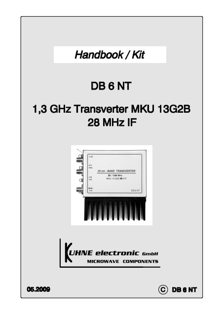
Introduction<br />
1.3 GHz Transverter MKU 13G2B-28<br />
DB6NT 5.2009<br />
The new transverter-kit for 23 cm represents the current status of amateur radio in the field of<br />
microwave technology. Revised by DB6NT, this transverter features excellent technical data<br />
and is suited for portable or stationary activities due to its small mechanical dimensions. By the<br />
use of additional power amplifiers this transverter module can be upgrated to a high<br />
performance transmit / receive system for 23 cm. All well-tried functions and features of the<br />
previous transverters are included.<br />
Our transverter kits are especially made for the 'normal' radio amateur who wants to build high<br />
quality microwave equipment by himself. This kit has been assembled for several times, so the<br />
reproducibility of the design is assured. We wish you good luck in 'homebrewing' the kit - but<br />
please read the following instructions very carefully!<br />
This transverter is designed for converting the frequency range 28 ... 30 MHz up to 1296 ...<br />
1298 MHz and vice versa. The circuit is built on gold-plated FR4 substrate, which is fabricated<br />
industrially and includes metallized through hole connections (vias). The receiver features a<br />
noise figure of typical 0.6 dB NF (max. 0.8 dB) and a gain of more than 20 dB. Therefore an<br />
additional LNA is not necessary. If a LNA is used, the receive gain of the transverter can be<br />
reduced by the potentiometer 'RX-Gain'. The transmitter achieves an output power of 400<br />
mW in the frequency range of 1296 ... 1298 MHz @ 28 MHz IF. Spurious rejection is better<br />
than 60 dB, harmonic rejection is better than 40 dB. When using this transverter module<br />
without an external power amplifier an external harmonic filter should be used. The output<br />
power is adjustable continously in the range 10 ... 400 mW by varying the gain with the<br />
potentiometer 'TX-Gain'. This output power level is sufficient for driving a MOSFET power<br />
amplifier or one to four power modules RA18H1213G (Mitsubishi).<br />
The IF power has to be in the range of 0.5 ... 3 W and must be customized by the<br />
potentiometer 'TX-Gain' (adapting a resistor allows the use of less than 10 mW). The applied<br />
power shouldn't be too high to avoid unwanted warming effects of the unit due to IF power<br />
dissipation. The complete circuit including IF-Switch, T/R-control and LO unit is built on a<br />
single board and accomodated in a tin-plate box (55x74x30 mm).<br />
For tuning only a simple DC voltmeter is required. All filters are helical filters with restricted<br />
tuning range, so tuning on ‘false’ resonance impossible.
Description<br />
The proven Colpitts oscillator for 105.667 MHz uses the FET SST310 in a grounded gate<br />
circuit. The frequency is adjusted by the ferrite tuning screw of the coil. The precision crystal<br />
heater QH40A mounted on the 40° C thermostat crystal stabilizes the crystal's temperature and<br />
keeps the frequency drift in limits. Extra pads are provided for fitting additional capacitors<br />
which can be selected for temperature compensation. For normal operations in a restricted<br />
temperature change environment the stability is sufficient. But for more serious work an<br />
external OCXO (1 mW) or the PLL-stabilized oscillator MKU XO 1PLL with 105.667 MHz<br />
is required. This external signal can be fed in at the source of the SST310, as indicated in the<br />
circuit diagram. In this case the crystal and the heater have to be replaced by an additional<br />
SMA female connector.<br />
The oscillator is followed by a quadrupler to 422 MHz which utilises a BFR92P transistor. The<br />
fourth harmonic is filtered by a helical filter and drives the tripler with the BFG93A. The<br />
output filter selects the harmonic at 1268 MHz. The power at this point is around 5 mW (7<br />
dBm). The IF signal is conducted from the mixer to the common IF connector via separate<br />
adjustable attenuators for RX and TX which are switched by pin diodes BAR64-03W. A<br />
voltage of at least +9 V activates the T/R-switching. Therefore the 10 m transceiver has to be<br />
modified. Whilst this method of T/R-switching via the IF coaxial cable is quite elegant, also a<br />
separate method via the PTT-manual input can be accomplished. An extra output is fitted for<br />
TX+, which can be used for external coaxial relays or PA’s. This output must be guarded by a<br />
0.63 A fuse - it's not safe in case of short circuit!<br />
Many coaxial relays have a too low isolation between the ports during the change-over. If the<br />
power amplifier (in a transmit-receive system) is switched too early, this may lead to damage<br />
or destruction of the input transistor in the preamplifier or converter.<br />
With a sequence controller, this trouble can be avoided. The sequence controller provides a<br />
control signal for the coaxial relay and it switches the voltage supply for the power amplifier.<br />
There is a time delay between the two signals to guarantee safe switching.<br />
The RX-chain uses a HEMT-FET amplifier and a MMIC as second stage. This combination<br />
provides an overall gain of >30 dB, which makes an extra IF-amplifier unnecessary. The<br />
received signal enters the MGF4918D via a 8.2 pF capacitor. The stages are coupled with the<br />
helical filter F4. The second stage is an ERA8-SM which is coupled to the mixer via the PINdiode<br />
switch and the second helical Filter F3. Beyond the PIN-switch and the helical Filter F3,<br />
which is used both for receive and transmit, a ERA-3-SM MMIC drives via a second helical<br />
filter F5 the preamplifier GALI4 and the power amplifier AH102A. This amplifier delivers 400<br />
mW output power. A directional coupler with a BAT15-03W Schottky diode provides a<br />
monitor DC voltage of the RF output power.
Construction<br />
To achieve a successful construction of this transverter the builder has to have<br />
experiences in the use and handling of SMD-parts. Furthermore experiences with<br />
smaller projects in microwave circuits are valuable. In any case the construction of this<br />
Transverter is not a beginners project.<br />
The usual ESD protection provisions should be obeyed.<br />
Construction Steps<br />
a. Solder the walls of the tinplate box and trim the PCB for fitting into the tinplate box.<br />
b. Mark the holes for the SMA-connectors and feedthrough capacitors.<br />
c. Drill holes for SMA-connectors and feedthrough capacitors.<br />
d. Solder PCB into the box. Use a 10.2 mm high piece of wood as a ruler to find the right<br />
height adjustment.<br />
e. Insert the 7809 (B) regulator into the PCB (remove the middle pin of the regulator!). Drill<br />
two holes for the heatsink and one hole for the regulator into the side wall of the box. The<br />
heatsink should be lie in the mid of the PCB. Diameter of the holes is 3 mm.<br />
e. Mount the parts onto the PCB. Mount the feedthrough caps. Solder the helical filters.<br />
Solder the regulator 7808 (A) with its heatsinks to the wall of the tinplate box. The FET<br />
08P06P should be fitted to the PCB by holding it tightly down and soldered. Clean the<br />
finished PCB with alcohol. The tuning screws of the resonators should be removed. Dry<br />
the module in a stove (1h at 80°C) or over night lying on a central heating.<br />
f. At least mount the 7809 (B).<br />
4. Alignment<br />
The following steps are necessary for the alignment of the transverter:<br />
a. Apply 12 V. Use a current limited (
e. Measure the drain voltage of the MGF4918D and adjust this voltage to 2 V by the 1k pot<br />
at the gate.<br />
f. Connect a 28 MHz receiver at the IF connector. Turn the RX-Gain and TX-Gain pots fully<br />
CCW. You will observe an increase in noise level. By tuning the helical filters F3 and F4<br />
you can maximise the noise output. If there is an indication of more than S1 at the 28 MHz<br />
transceiver you should adjust the RX-Gain Pot accordingly.<br />
g. Connect a 50 Ohm dummy load to the TX output. Switch the transverter to transmit by<br />
grounding the PTT input. Drive the transverter with 0.5 ... 3 W on 28 MHz. Measure the<br />
monitor voltage at MON OUT. It should read 2 ... 3 V. Adjust the TX-Gain pot to a<br />
reading of about 1 V. Now the helical filter F5 and the LO-filter F2 can be readjusted to<br />
maximum output.<br />
h. Reduce the TX-Gain by clockwise rotation of the TX-Gain pot until the TX output starts to<br />
decrease. A value 80% of the maximum assures linear operation.<br />
i. Connect antenna to RX input. Adjust the XO until a known beacon reads the correct<br />
frequency.<br />
j. Take low resistance carbonised foam and glue it into the bottom cover. This damps the<br />
resonance of the box. The heatsink should be mounted onto a chassis plate to further reduce<br />
the thermal resistance.<br />
A 1.3 GHz coaxial relay must be used for RX/TX switch.<br />
Ready! Go on for QSO!
My special thanks to Friedhold DG0EG who made this transverter ready to got into<br />
production by his experience in assembly and many helpful suggestions. Furthermore I thank<br />
Lorenz DL6NCI who verified the reproducibility of the design by building this transverter.<br />
Literature:<br />
1.) “Transverter for 1.3 GHz by DB6NT” DUBUS 4.92 (Technik IV)<br />
2.) “1.3 GHz Transverter MKII by DB6NT” DUBUS 2.2000 (Technik VI)<br />
3.) <strong>Download</strong> of the kit description:<br />
http://www.kuhne-<strong>electronic</strong>.de<br />
Purchase:<br />
Ready made modules and kits:<br />
KUHNE <strong>electronic</strong> GmbH<br />
Scheibenacker 3<br />
D-95180 BERG<br />
Tel.: 0049 (0) 9293 800 939<br />
Fax: 0049 (0) 9293 800 938<br />
Email: info@kuhne-<strong>electronic</strong>.de<br />
www.db6nt.de<br />
All rights reserved to the author DB 6 NT Michael <strong>Kuhne</strong><br />
For operating the high frequency modules the legal instructions have to be considered.
Die Ausgangsleistung des Transverters MKU 13 G2B sollte bei Betrieb mit einem<br />
nachgeschalteten Leistungsverstärker MKU PA 133 HY2 mit dem TX-Gain Regler auf<br />
ca. 50 mW eingestellt werden. Die Baugruppen können zusammen mit dem Koaxialrelais<br />
in einem wetterfesten Gehäuse mit Kühlkörper direkt an der Antenne montiert werden.<br />
Dadurch wird die Dämpfung durch lange Koaxkabel vermieden.<br />
The output power of the transverter MKU 13G2B should be adjusted to 50 mW with the internal<br />
potentiometer 'TX-Gain' when using the power amplifier MKU PA 133 HY2. These components<br />
can be installed together with the coaxial relay in a weather-proof case direct at the antenne to reduce cable losses.<br />
Achtung! Viele Koaxial- Relais haben während des Umschaltvorganges eine zu geringe<br />
Entkoppelung zwischen Sende- und Empfangskontakt. Dieses kann zur<br />
Zerstörung des Eingangstransistors im Konverter oder des Vorverstärkers<br />
führen. Das Relais sollte eine Entkoppelung von 50 dB erreichen.<br />
Die Leistung auf den RX - Eingang darf 1mW nicht überschreiten.<br />
Es wird dringend die Verwendung einer Sequenzsteuerung empfohlen.<br />
Attention! Many coaxial relays have a too low isolation between the ports during the<br />
change-over. If the power amplifier is switched too early, this may lead to<br />
damage the input transistor of the RX-path of the transverter. The relay should<br />
achieve an isolation of 50dB. The RF power that leads the RX input must not<br />
exceed 1mW!<br />
The use of a sequence controler is strongly recommended.<br />
SEQ 1<br />
SEQ 2 / 3
Precision crystal heater QH40A<br />
This precision crystal heater provides temperature compensation for crystals, usually found within crystal oscillators.<br />
The assembled circuit, which is built on AL2O3 ceramic substrate, should be mounted against the crystal<br />
using heat shrink tubing. The circuit heats the crystal to a temperature of 40.8° C with an accuracy of better than<br />
0.1° C. This provides high frequency stability over the temperature range of -5 to +40° C. This crystal heater is a<br />
reasonable alternative to completely heated OCXO´s.<br />
Thin wires should be used for the connections to avoid heat transfer and mechanical load. For operation in ambient<br />
temperatures of 10° C or below, add some polystyrene insulation.<br />
Reverse polarity of the supply voltage can lead to the destruction of the circuit.<br />
Specifications:<br />
Adjustment tolerance: 40,8 °C +/- 1,5 °C<br />
Regulation accuracy: better 0,1 °C<br />
Operating voltage: 8...12 V<br />
Inrush current: ca. 80 mA<br />
Dimensions: 10,5 x 14,0 x 3,5 mm<br />
Assembling:<br />
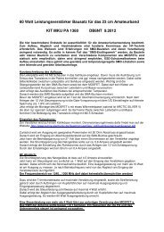
1. Solder the wires to the pins provided.<br />
The S-shape of the wires (Fig. 1) reduces the mechanical load on the heater plate.<br />
2. Warm the heat shrink tubing to hold the circuit next to the crystal (Fig. 2), ensure that the temperature is not<br />
too high.<br />
3. Install the crystal heater (Fig. 3).<br />
Fig. 1 Fig. 2 Fig. 3
Sicherheitshinweise – für Fertigmodule, Bausätze, Bauteile<br />
Achtung: Verletzungsgefahr!<br />
Weißblech / Neusilbergehäuse / Kühlkörper sind sehr scharfkantig. Bitte vorsichtig damit umgehen.<br />
Darf nicht in die Hände von Kindern gelangen. Vorsicht bei Deckelmontage, Quetschungsgefahr der<br />
Finger, Schnittgefahr.<br />
Benutzung der Baugruppen, Montage der Bausätze darf nur durch autorisiertes Fachpersonal oder<br />
lizenzierte Funkamateure erfolgen.<br />
Bausätze / Fertigmodule enthalten Kleinteile, dürfen nicht in die Hände von Kindern und unbefugten<br />
Personen gelangen. Verletzungsgefahr! Verschluckungsgefahr von Kleinteilen. Teile dürfen nicht in<br />
den Mund genommen werden!<br />
Elektronikbaugruppen dürfen nur innerhalb der Spezifikation betrieben werden. Maximale<br />
Versorgungsspannung darf nicht überschritten werden!<br />
Verpackungsmaterial (Plastiktüten, Styropor usw.), Kleinteile, dürfen nicht in die Hände von Kindern<br />
gelangen. Erstickungsgefahr, Verschluckungsgefahr, kein Spielzeug!<br />
Die Anleitung / das Messprotokoll bitte für späteren Gebrauch aufbewahren.<br />
Entsorgen Sie die Module / Bauteile nur bei den vorhergesehenen Sammelstellen.<br />
----------------------------------------------------------------------------------------------------------------------------------------<br />
Safety instructions – for readymade modules, kits, units<br />
Caution: Risk of injury!<br />
Tin plate / German Silver / cases / heat sink are very sharp-edged. Please handle with care. It should<br />
not get into the hands of children. Be careful when assembling the top cover, danger of contusion and<br />
cutting.<br />
Using of the components and assembling the kits should only be done by authorized and qualified<br />
personnel or licensed radio amateurs.<br />
Kits / readymade modules contain small parts, and should not get into the hands of children or<br />
unauthorized persons. Risk of injury! Danger of swallowing small parts. The parts should not be taken<br />
into the mouth!<br />
Electronic components are only to be run within the specifications. Maximum supply voltage should<br />
not be exceeded!<br />
Packing material (plastic bags, polystyrene etc.), small parts, should not get into the hands of children.<br />
Danger of suffocation and swallowing – no toys!<br />
Please keep the manual / measuring report for future use.<br />
Please dispose the modules / components only at collection points which are designated for it.<br />
<strong>Kuhne</strong> <strong>electronic</strong> GmbH - Scheibenacker 3 - D-95180 Berg - Tel. +9293-800 939 - Fax +9293-800 938