Download - Kuhne electronic
Download - Kuhne electronic
Download - Kuhne electronic

You also want an ePaper? Increase the reach of your titles
YUMPU automatically turns print PDFs into web optimized ePapers that Google loves.
Introduction<br />
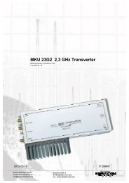
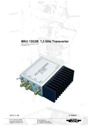
1.3 GHz Transverter MKU 13G2B-28<br />
DB6NT 5.2009<br />
The new transverter-kit for 23 cm represents the current status of amateur radio in the field of<br />
microwave technology. Revised by DB6NT, this transverter features excellent technical data<br />
and is suited for portable or stationary activities due to its small mechanical dimensions. By the<br />
use of additional power amplifiers this transverter module can be upgrated to a high<br />
performance transmit / receive system for 23 cm. All well-tried functions and features of the<br />
previous transverters are included.<br />
Our transverter kits are especially made for the 'normal' radio amateur who wants to build high<br />
quality microwave equipment by himself. This kit has been assembled for several times, so the<br />
reproducibility of the design is assured. We wish you good luck in 'homebrewing' the kit - but<br />
please read the following instructions very carefully!<br />
This transverter is designed for converting the frequency range 28 ... 30 MHz up to 1296 ...<br />
1298 MHz and vice versa. The circuit is built on gold-plated FR4 substrate, which is fabricated<br />
industrially and includes metallized through hole connections (vias). The receiver features a<br />
noise figure of typical 0.6 dB NF (max. 0.8 dB) and a gain of more than 20 dB. Therefore an<br />
additional LNA is not necessary. If a LNA is used, the receive gain of the transverter can be<br />
reduced by the potentiometer 'RX-Gain'. The transmitter achieves an output power of 400<br />
mW in the frequency range of 1296 ... 1298 MHz @ 28 MHz IF. Spurious rejection is better<br />
than 60 dB, harmonic rejection is better than 40 dB. When using this transverter module<br />
without an external power amplifier an external harmonic filter should be used. The output<br />
power is adjustable continously in the range 10 ... 400 mW by varying the gain with the<br />
potentiometer 'TX-Gain'. This output power level is sufficient for driving a MOSFET power<br />
amplifier or one to four power modules RA18H1213G (Mitsubishi).<br />
The IF power has to be in the range of 0.5 ... 3 W and must be customized by the<br />
potentiometer 'TX-Gain' (adapting a resistor allows the use of less than 10 mW). The applied<br />
power shouldn't be too high to avoid unwanted warming effects of the unit due to IF power<br />
dissipation. The complete circuit including IF-Switch, T/R-control and LO unit is built on a<br />
single board and accomodated in a tin-plate box (55x74x30 mm).<br />
For tuning only a simple DC voltmeter is required. All filters are helical filters with restricted<br />
tuning range, so tuning on ‘false’ resonance impossible.