extra 300 hp - Graupner
extra 300 hp - Graupner
extra 300 hp - Graupner

Erfolgreiche ePaper selbst erstellen
Machen Sie aus Ihren PDF Publikationen ein blätterbares Flipbook mit unserer einzigartigen Google optimierten e-Paper Software.
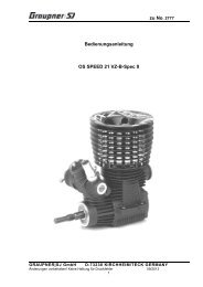
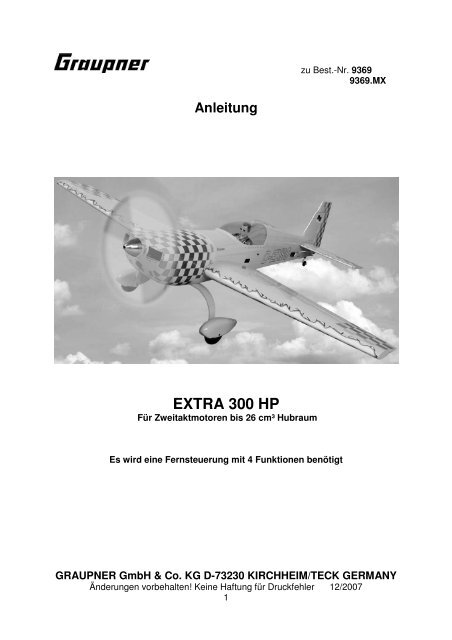
Anleitung<br />
EXTRA <strong>300</strong> HP<br />
Für Zweitaktmotoren bis 26 cm³ Hubraum<br />
Es wird eine Fernsteuerung mit 4 Funktionen benötigt<br />
zu Best.-Nr. 9369<br />
9369.MX<br />
GRAUPNER GmbH & Co. KG D-73230 KIRCHHEIM/TECK GERMANY<br />
Änderungen vorbehalten! Keine Haftung für Druckfehler 12/2007<br />
1
Technische Daten<br />
Spannweite ca. 1700 mm<br />
Rumpflänge ohne Spinner ca. 1590 mm<br />
Flächeninhalt ca. 55 dm²<br />
Höhenleitwerksinhalt ca. 12 dm²<br />
Gesamtflächeninhalt ca. 67 dm²<br />
Fluggewicht je nach Ausrüstung ca. 4800 g<br />
EWD 0-0.5 Grad<br />
Schwerpunkt ca. 100-110 mm hinter der Nasenleiste rechts<br />
und links neben dem Rumpf<br />
Achtung: Dieses Modell ist kein Spielzeug!<br />
Sollten Sie mit solch motorisiertem Modell keine Erfahrung haben, wenden Sie sich<br />
bitte an erfahrene Modellflieger, die Sie unterstützen können. Es könnte zu<br />
Verletzungen kommen, wenn das Modell ohne Vorkenntnisse in Betrieb genommen<br />
wird. Denken Sie an die Sicherheit und Ihre Gesundheit.<br />
Wichtig! Bevor Sie mit dem Bau beginnen!<br />
Auch wenn Sie schon viele RC-Modelle gebaut haben, lesen Sie diese Anleitung<br />
genauestens durch und kontrollieren Sie die Teile dieses Bausatzes auf<br />
Vollständigkeit. Es wurde viel Mühe darauf verwand, den Aufwand möglichst einfach<br />
zu machen, ohne die Sicherheit zu beeinträchtigen.<br />
Hinweis zur Folienbespannung<br />
Auf Grund von starken Wetteränderungen (Temperatur, Feuchtigkeit etc.) können in<br />
der Bespannfolie kleine Falten auftreten. In seltenen Fällen auch ein Verzug der<br />
Bauteile. Dies liegt in der Natur der Holzbauweise mit Folienbespannung. Es kann,<br />
wie folgt, mit einem Heißluftgebläse (Fön), wie sie für den Modellbauer angeboten<br />
werden, wieder korrigiert werden.<br />
Falten: Mit Warmluft anblasen und mit weichem Tuch anreiben.<br />
Verzogene Fläche: Fläche dem Verzug entgegen leicht verdreht aufspannen und mit<br />
Warmluft die Bespannung wieder glätten.<br />
Vorsicht! Nicht mehr Wärme zuführen, als unbedingt notwendig. Bei zu heißem<br />
Bügeleisen schmilzt die Folie und es entstehen Löcher.<br />
Das weitgehend vorgefertigte Modell benötigt nur noch wenig Bauzeit. Aber die<br />
verbleibenden Arbeiten sind wichtig und müssen sorgfältig ausgeführt werden. Von<br />
deren einwandfreier Ausführung hängt es ab, ob das Modell letztlich die<br />
vorgesehene Festigkeit und Flugeigenschaften haben wird; deshalb langsam und<br />
präzise arbeiten!<br />
Wenn Blechschrauben in Holz eingeschraubt werden, diese durch Weißleim<br />
gegen Lösen sichern: Weißleim in Bohrung einspritzen und Schraube<br />
eindrehen.<br />
GRAUPNER GmbH & Co. KG D-73230 KIRCHHEIM/TECK GERMANY<br />
Änderungen vorbehalten! Keine Haftung für Druckfehler 12/2007<br />
2
Sicherheitshinweise und Warnungen betreffend<br />
Motor-Flugmodelle mit Verbrennungsmotoren<br />
• Vor dem Versuch der ersten Inbetriebnahme muss die gesamte Betriebs-<br />
und Montageanleitung sorgfältig gelesen werden.<br />
• Diese Sicherheitshinweise sind Bestandteil dieser Anleitung und müssen<br />
zusammen mit der Bedienungsanleitung sorgfältig aufbewahrt und im Falle<br />
einer Weitergabe dem nachfolgenden Benutzer unbedingt mit ausgehändigt<br />
werden.<br />
• Motorflugmodelle sind sehr anspruchsvolle und gefährliche Gegenstände<br />
und erfordern vom Betreiber einen hohen Sachverstand, Können und<br />
Verantwortungsbewusstsein.<br />
• Motorflugmodelle sind für Personen unter 18 Jahren nicht geeignet.<br />
• Ein Betrieb darf nur unter Anleitung und Aufsicht eines Erwachsenen<br />
erfolgen, der mit den sich daraus ergebenden Gefahren vertraut ist.<br />
• Der Betreiber muss im Besitz seiner vollen körperlichen und geistigen<br />
Fähigkeiten sein. Wie beim Autofahren, ist der Betrieb des Flugmodells<br />
unter Alkohol oder Drogeneinwirkung nicht erlaubt.<br />
• Ferngesteuerte Flugmodelle dürfen nur für den vom Hersteller<br />
vorgesehenen Zweck eingesetzt werden, also als nicht manntragendes<br />
Sportgerät. Eine anderweitige Verwendung ist verboten.<br />
• Ein Modell kann nur funktionstüchtig sein und den Erwartungen<br />
entsprechen, wenn es im Sinne der Bauanleitung sorgfältigst gebaut oder<br />
montiert wurde. Eigenmächtige Veränderungen von Konstruktion und<br />
Material sind nicht zulässig. Nur ein vorsichtiger und überlegter Umgang<br />
beim Betrieb schützt vor Personen- und Sachschäden. Niemand würde sich<br />
in ein Sportflugzeug setzen und - ohne vorausgegangene Schulung -<br />
versuchen, damit zu fliegen. Auch Modellfliegen will gelernt sein! Bitte<br />
wenden Sie sich dazu an erfahrene Modellflieger, an Vereine oder<br />
Modellflugschulen. Ferner sei auf den Fachhandel und die einschlägige<br />
Fac<strong>hp</strong>resse verwiesen.<br />
• Unbedingt die Angaben zur Schwerpunktlage und zu Ruderausschlägen<br />
beachten! Das Modell muss entsprechend justiert werden.<br />
• Fernlenkanlage: Sich vergewissern, dass die verwendete Frequenz frei ist.<br />
Erst dann einschalten! RC-Anlage öfters kontrollieren; auch sie ist<br />
gewissem Verschleiß ausgesetzt. Funkstörungen, verursacht durch<br />
Unbekannte, können stets ohne Vorwarnung auftreten! Das Modell ist dann<br />
steuerlos und unberechenbar! Fernlenkanlage nie unbeaufsichtigt lassen,<br />
um ein Betätigen durch Dritte zu verhindern. Immer auf vollgeladene Akkus<br />
achten, da sonst keine einwandfreie Funktion der RC-Anlage gewährleistet<br />
ist.<br />
• Warnungen müssen unbedingt beachtet werden. Sie beziehen sich auf<br />
Dinge und Vorgänge, die bei einer Nichtbeachtung zu schweren - in<br />
Extremfällen tödlichen Verletzungen oder bleibenden Schäden führen<br />
können.<br />
• Sie alleine sind verantwortlich für den sicheren Betrieb Ihres Modells und<br />
Motors.<br />
GRAUPNER GmbH & Co. KG D-73230 KIRCHHEIM/TECK GERMANY<br />
Änderungen vorbehalten! Keine Haftung für Druckfehler 12/2007<br />
3
• Fragen, die die Sicherheit beim Betrieb von Modell und Motor betreffen,<br />
werden Ihnen vom Fachhandel gerne beantwortet.<br />
• Luftschrauben und generell alle sich drehenden Teile, die durch einen<br />
Motor angetrieben werden, stellen eine ständige Verletzungsgefahr dar. Sie<br />
dürfen mit keinem Körperteil berührt werden! Eine schnell drehende<br />
Luftschraube kann z. B. einen Finger abschlagen!<br />
• Sich niemals in der Drehebene von Luftschrauben aufhalten! Es könnte sich<br />
doch einmal ein Teil davon lösen und mit hoher Geschwindigkeit und viel<br />
Energie wegfliegen und Sie oder Dritte Personen treffen. Darauf achten,<br />
dass kein sonstiger Gegenstand mit einer laufenden Luftschraube in<br />
Berührung kommt!<br />
• Vorsicht bei losen Kleidungsstücken wie Schals, weiten Hemden usw.: sie<br />
werden vom Propellerstrahl angesaugt und können in den<br />
•<br />
Luftschraubenkreis gelangen.<br />
Informieren Sie alle Passanten und Zuschauer vor der Inbetriebnahme über<br />
alle möglichen Gefahren, die von Ihrem Modell ausgehen und ermahnen<br />
diese, sich in ausreichendem Schutzabstand (wenigstens 5 m) aufzuhalten.<br />
• Modellflug darf nur bei "normalen" Außentemperaturen betrieben werden, d.<br />
h. in einem Bereich von - 5º C bis + 35º C. Extremere Temperaturen können<br />
zu Veränderungen von z. B. Akku-Kapazität und Werkstoffeigenschaften<br />
und anderem führen.<br />
• Modellkraftstoff ist giftig! Nicht in Kontakt mit Augen oder Mund bringen!<br />
Eine Aufbewahrung ist nur in deutlich gekennzeichneten Behältern und<br />
außerhalb der Reichweite von Kindern zulässig.<br />
• Motor nie in geschlossenen Räumen, wie Keller, Garage usw. laufen lassen.<br />
Auch Modellmotoren entwickeln tödliches Kohlenmonoxyd-Gas.<br />
• Nur im Freien betreiben!<br />
• Klebstoffe und Lacke enthalten Lösungsmittel, die unter Umständen<br />
gesundheitsschädlich sein können. Beachten Sie daher unbedingt auch die<br />
entsprechenden Hinweise und Warnungen der entsprechenden Hersteller.<br />
• Modellkraftstoff ist leicht entzündlich und brennbar; fernhalten von offenem<br />
Feuer, übermäßiger Wärme, irgendwelchen Quellen von Funken oder<br />
sonstigen Dingen, die zu einer Entzündung führen können. In der direkten<br />
Umgebung von Kraftstoff oder Kraftstoffdämpfen darf nicht geraucht<br />
werden.<br />
• Ein Modellmotor entwickelt beim Betrieb eine Menge Hitze. Motor und<br />
Schalldämpfer sind darum während des Betriebs und noch eine Weile<br />
danach sehr heiß. Bei Berührung kann das zu ernsthaften Verbrennungen<br />
führen. Vorsicht bei Einstellarbeiten! Schutzhandschuhe tragen! In<br />
Extremfällen können auch Brände ausgelöst werden.<br />
• Während des Betriebs des Motors treten nicht nur giftige und heiße Abgase<br />
aus dem Auspuff aus, sondern auch sehr heiße und flüssige<br />
•<br />
Verbrennungsrückstände, die zu Verbrennungen führen können.<br />
Nach dem Betrieb sind Kraftstoffreste aus Tank und Motor zu entfernen.<br />
• Überprüfen Sie vor und nach jeder Inbetriebnahme das Modell und alle an<br />
ihm angekoppelten Teile (z. B. Luftschrauben, Ruderanlenkungen, Ruder<br />
usw.) auf mögliche Beschädigungen. Das Modell darf erst nach Beseitigung<br />
aller Mängel in Betrieb genommen werden.<br />
GRAUPNER GmbH & Co. KG D-73230 KIRCHHEIM/TECK GERMANY<br />
Änderungen vorbehalten! Keine Haftung für Druckfehler 12/2007<br />
4
• Das Anlassen des Motors erfolgt mit einem Elektrostarter, der evtl. mit<br />
einem zum Modell passenden Adapter ausgerüstet ist. Als alternative<br />
Anwerfhilfe bei Flächenmodellen kann z. B. ein Rundholz mit einem<br />
aufgesteckten Stück Wasserschlauch verwendet werden.<br />
• Modellmotoren entwickeln im Betrieb u. U. einen Schallpegel der weit<br />
größer als 85 dB (A) sein kann, dabei unbedingt Gehörschutz tragen.<br />
Motoren nie ohne Schalldämpfer laufen lassen. Aber auch mit<br />
Schalldämpfer können Modellmotoren Nachbarn stören. Ruhezeiten<br />
beachten!<br />
• Steht ein Modell mit drehender Luftschraube z. B. auf sandigem Grund, so<br />
wird Sand oder Staub angesaugt und herumgewirbelt, der auch ins Auge<br />
fliegen kann. Schutzbrille tragen!<br />
• Darauf achten, dass weder der Glühkerzenstecker, noch das dazugehörige<br />
Kabel mit der sich drehenden Luftschraube oder anderen sich drehenden<br />
Teilen in Berührung kommt. Auch das Drosselgestänge daraufhin<br />
überprüfen.<br />
• Besondere Vorsicht ist geboten, wenn das Modell mit laufendem Motor<br />
getragen wird. Drehende Teile dabei weit von sich weghalten!<br />
• Stets auf ausreichende Kraftstoffmenge im Tank achten. Der Tankinhalt<br />
kann nie restlos ausgeflogen werden.<br />
• Nie Personen überfliegen.<br />
• Nie auf Personen zufliegen.<br />
• Auf ausreichenden Abstand zu Wohngebieten achten, mindestens 1,5 km<br />
Luftlinie. Am besten als Club-Mitglied auf zugelassenem Modellflugplatz<br />
fliegen. Ausreichenden Abstand zu Hochspannungsleitungen halten.<br />
• Beim Hantieren am Motor unbedingt auf gute Standfestigkeit achten, auch<br />
das Modell muss dabei gut festgehalten werden.<br />
• Während des Start- und Landevorgangs müssen die Start- und<br />
Landeflächen frei von unbefugten Personen und beweglichen Hindernissen<br />
sein.<br />
• Das Flugmodell muss während des gesamten Fluges ständig beobachtet<br />
werden können. Es hat bemannten Luftfahrzeugen stets auszuweichen.<br />
• Betreiben Sie Ihr Modell nie auf öffentlichen Straßen, Plätzen, Schulhöfen,<br />
Park- oder Spielplätzen usw. und sorgen Sie dafür, dass Sie es stets unter<br />
voller Kontrolle haben.<br />
• Um einen laufenden Motor jederzeit anhalten zu können, muss man die<br />
Drossel so eingestellt haben, dass das Vergaserküken ganz geschlossen<br />
wird, wenn Steuerknüppel und Trimmhebel in die Leerlaufendstellung<br />
gebracht werden. Geht dies nicht, wird die Kraftstoffzufuhr durch<br />
Abklemmen oder Abziehen des Verbindungsschlauches zum Tank<br />
unterbrochen. Niemals versuchen, den Motor am Schwungrad, Propeller<br />
oder Spinner anzuhalten!<br />
• Jeder Modellflieger hat sich so zu verhalten, dass die öffentliche Sicherheit<br />
und Ordnung, insbesondere andere Personen und Sachen sowie die<br />
Ordnung des Modellflugbetriebs nicht gefährdet oder gestört wird.<br />
• Rechtlich gesehen ist ein Flugmodell ein Luftfahrzeug und unterliegt<br />
entsprechenden Gesetzen, die unbedingt eingehalten werden müssen.<br />
GRAUPNER GmbH & Co. KG D-73230 KIRCHHEIM/TECK GERMANY<br />
Änderungen vorbehalten! Keine Haftung für Druckfehler 12/2007<br />
5
• Die Broschüre »Modellflugrecht, Paragrafen und mehr«, Best.-Nr. 8034.02<br />
stellt eine Zusammenfassung dieser Gesetze dar; sie kann auch beim<br />
Fachhandel eingesehen werden. Bei Modellen mit Verbrennungsmotoren<br />
muss z. B. eine Aufstiegserlaubnis vorliegen und es besteht<br />
Versicherungspflicht. Ferner müssen Auflagen, die die Fernlenkanlage<br />
betreffen, beachtet werden.<br />
• Mit diesen Hinweisen soll auf die vielfältigen Gefahren hingewiesen werden,<br />
die durch unsachgemäße und verantwortungslose Handhabung entstehen<br />
können. Richtig und gewissenhaft betrieben ist Modellflug eine kreative,<br />
lehrreiche und erholsame Freizeitgestaltung.<br />
• Das weitgehend vorgefertigte Modell benötigt nur noch wenig Bauzeit. Aber<br />
die verbleibenden Arbeiten sind wichtig und müssen sorgfältig ausgeführt<br />
werden. Von deren einwandfreier Ausführung hängt es ab, ob das Modell<br />
letztlich die vorgesehene Festigkeit und Flugeigenschaften haben wird;<br />
deshalb langsam und präzise arbeiten!<br />
Wichtige Sicherheitshinweise<br />
Sie haben einen Bausatz erworben, aus dem – zusammen mit entsprechendem<br />
geeigneten Zubehör – ein funktionsfähiges RC-Modell fertiggestellt werden kann. Die<br />
Einhaltung der Montage- und Betriebsanleitung im Zusammenhang mit dem Modell<br />
sowie die Installation, der Betrieb, die Verwendung und Wartung der mit dem Modell<br />
zusammenhängenden Komponenten können von GRAUPNER nicht überwacht<br />
werden. Daher übernimmt GRAUPNER keinerlei Haftung für Verluste, Schäden oder<br />
Kosten, die sich aus dem fehlerhaften Betrieb, aus fehlerhaftem Verhalten bzw. in<br />
irgendeiner Weise mit dem vorgenannten zusammenhängend ergeben. Soweit vom<br />
Gesetzgeber nicht zwingend vorgeschrieben, ist die Verpflichtung der Firma<br />
GRAUPNER zur Leistung von Schadensersatz, aus welchem Grund auch immer<br />
ausgeschlossen (inkl. Personenschäden, Tod, Beschädigung von Gebäuden sowie<br />
auch Schäden durch Umsatz- oder Geschäftsverlust, durch Geschäftsunterbrechung<br />
oder andere indirekte oder direkte Folgeschäden), die von dem Einsatz des Modells<br />
herrühren.<br />
Die Gesamthaftung ist unter allen Umständen und in jedem Fall beschränkt auf den<br />
Betrag, den Sie tatsächlich für dieses Modell gezahlt haben.<br />
Die Inbetriebnahme und der Betrieb des Modells erfolgt einzig und allein auf<br />
Gefahr des Betreibers. Nur ein vorsichtiger und überlegter Umgang beim<br />
Betrieb schützt vor Personen- und Sachschäden.<br />
Prüfen Sie vor dem ersten Einsatz des Modells, ob Ihre Privat-Haftpflichtversicherung<br />
den Betrieb von Modellen dieser Art mit einschließt. Schließen Sie gegebenenfalls<br />
eine spezielle RC-Modell-Haftpflichtversicherung ab.<br />
Diese Sicherheitshinweise müssen unbedingt aufbewahrt werden und müssen bei<br />
einem Weiterverkauf des Modells an den Käufer weitergegeben werden.<br />
Garantiebedingungen<br />
Die Garantie besteht aus Umtausch von solchen Teilen, die während der<br />
Garantiezeit von 24 Monaten, ab dem Datum des Kaufes nachgewiesene<br />
Fabrikations- oder Materialfehler aufweisen. Weitergehende Ansprüche sind<br />
GRAUPNER GmbH & Co. KG D-73230 KIRCHHEIM/TECK GERMANY<br />
Änderungen vorbehalten! Keine Haftung für Druckfehler 12/2007<br />
6
ausgeschlossen. Transport-, Verpackungs-, Fracht- und Fahrtkosten gehen zu<br />
Lasten des Käufers. Für Transportschäden wird keine Haftung übernommen.<br />
Bei der Einsendung an GRAUPNER bzw. an die für das jeweilige Land<br />
zuständige Servicestelle sind eine sachdienliche Fehlerbeschreibung und die<br />
Rechnung mit dem Kaufdatum beizufügen. Die Garantie ist hinfällig, wenn der<br />
Ausfall des Teils oder des Modells von einem Unfall, unsachgemäßer<br />
Behandlung oder falscher Verwendung herrührt.<br />
Folgende Punkte müssen unbedingt beachtet werden:<br />
• Kontrollieren Sie, bevor Sie das Modell starten, dieses auf eine sichere Funktion<br />
der Fernsteuerung sowie die Steckverbindungen auf sichere und feste<br />
Verbindung.<br />
• Die Akkus müssen geladen sein und die Reichweite der Fernsteuerung muss<br />
überprüft worden sein. Besonders die Sender- und Empfängerakkus müssen vor<br />
jedem Start geladen werden.<br />
• Prüfen Sie, ob der von Ihnen genutzte Kanal frei ist. Fliegen Sie niemals, wenn<br />
Sie sich nicht sicher sind, ob der Kanal frei ist.<br />
• Beachten Sie die Empfehlungen und Hinweise zu Ihrer Fernsteuerung und<br />
Zubehörteilen.<br />
• Achten Sie darauf, dass die Servos in ihrem Verfahrweg mechanisch nicht<br />
begrenzt werden.<br />
• Batterien und Akkus dürfen nicht kurzgeschlossen werden.<br />
• Entnehmen Sie die Akkus bei Transport und Nichtgebrauch des Modells.<br />
• Setzen Sie das Modell nicht starker Luftfeuchtigkeit, Hitze, Kälte sowie Schmutz<br />
aus.<br />
• Sichern Sie das Modell und RC-Komponenten beim Transport gegen<br />
Beschädigung sowie Verrutschen.<br />
Überprüfung vor dem Start<br />
Vor jedem Einsatz korrekte Funktion und Reichweite überprüfen. Dazu<br />
Senderantenne einschrauben und dann auf vollständige Länge ausziehen. Dann den<br />
Sender einschalten, ebenso den Empfänger. Aus entsprechendem Abstand vom<br />
Modell kontrollieren, ob alle Ruder einwandfrei funktionieren und in der richtigen<br />
Richtung ausschlagen.<br />
Diese Überprüfung bei laufendem Motor wiederholen, während ein Helfer das Modell<br />
festhält.<br />
Beim erstmaligen Steuern eines Flugmodells ist es von Vorteil, wenn ein erfahrener<br />
Helfer bei der Überprüfung und den ersten Flügen zur Seite steht.<br />
Pflege und Wartung<br />
• Säubern Sie das Modell nach jedem Gebrauch. Entfernen Sie Schmutzreste auch<br />
vom Propeller. Säubern Sie das Modell und die RC-Komponenten nur mit<br />
geeigneten Reinigungsmitteln. Informieren Sie sich hierzu bei Ihrem Fachhändler.<br />
• Wenn das Modell längere Zeit nicht betrieben werden soll, müssen alle bewegten<br />
Teile gesäubert und neu geschmiert werden.<br />
GRAUPNER GmbH & Co. KG D-73230 KIRCHHEIM/TECK GERMANY<br />
Änderungen vorbehalten! Keine Haftung für Druckfehler 12/2007<br />
7
Hinweise zum Bau des Modells<br />
• Vor dem Bau des Modells sollte man unbedingt die Anleitung bis zum Schluss<br />
lesen. Achten Sie beim Einsatz von Werkzeugen auf die möglichen Gefahren.<br />
• Verwenden Sie nur geeignete Kabel, die den im Betrieb auftretenden<br />
Stromstärken genügen.<br />
• Säubern Sie jede Klebeverbindung von Fettresten, bevor Sie diese verkleben.<br />
Dies kann z. B. durch Anschleifen und mit einem nicht nachfettenden Spülmittel<br />
geschehen. Das gleiche gilt für die zu lackierenden Oberflächen um eine gute<br />
Haltbarkeit der Farbe zu erreichen. Vor dem Festkleben von Teilen, unbedingt die<br />
entsprechenden Flächen (besonders bei GFK-Rümpfen) sorgfältig mit feinem<br />
Schleifpapier aufrauen und gründlich mit z. B. Aceton entfetten. Sonst ist keine<br />
ausreichende Verklebung gewährleistet.<br />
Zusätzlich benötigtes Zubehör<br />
Motor und Zubehör<br />
Motor<br />
Best.-Nr.<br />
OS MAX 120 AX<br />
2703<br />
OS MAX FS 120 SURPASS<br />
1886<br />
OS MAX FT-160<br />
1412<br />
Fernlenkanlage<br />
Hubraum Schalldämpfer Distanzstück Luftschraube<br />
cm³ Best.-Nr. Best.-Nr. Best.-Nr.<br />
20,0 2703.33 2703.36A 38 x 25 cm<br />
1318.38.25<br />
19,96 1886.33 - 36 x18 cm<br />
1316.36.18<br />
2x13,26 1431.80 dazu - 38 x 20 cm<br />
3332.7<br />
Krümmer und<br />
1001.145<br />
flex.Rohr<br />
(je 2 St.erford.)<br />
1318.38.20<br />
Sie muss über mindestens 4 Steuerfunktionen und 6 Servos verfügen. Ferner<br />
sollte am Sender eine Servo-Drehrichtungsumkehr möglich sein.<br />
Besonders empfohlen: Computer-System mx-16 bis mc-24. Es können Servos mit<br />
Normalabmessungen eingebaut werden. Als Empfängerakku empfehlen wir: SAFT<br />
4NH-<strong>300</strong>0 CS Best.-Nr.2566, welcher vor und nach dem Flugbetrieb stets gut<br />
gewartet werden muss, d. h., bis zum Erreichen der angegebenen Kapazität muss<br />
der Akku mehrmals geladen und wieder entladen werden.<br />
GRAUPNER GmbH & Co. KG D-73230 KIRCHHEIM/TECK GERMANY<br />
Änderungen vorbehalten! Keine Haftung für Druckfehler 12/2007<br />
8
Für die Verbindung der Querruder- und Höhenruderservos mit dem Empfänger wird<br />
ein Klapp-Ferritkern, Best.-Nr. 98516.1 benötigt. Zum Verbinden der<br />
Querruderservokabel mit dem Empfänger empfiehlt es sich in die entsprechenden<br />
Buchsen am Empfänger jeweils ein Verlängerungskabel Best.-Nr. 3935.18<br />
einzustecken. Die beiden Höhenruderservos mit jeweils einem Verlängerungskabel<br />
Best.Nr.3935.11 die Querruderservos mit jeweils einem Best.-Nr. 3035.18<br />
verlängern.<br />
Als Servohebel wird die Best.-Nr. 3544 benötigt.<br />
Schaumgummi zur Lagerung von Empfänger und Batterie, enthalten.<br />
Klebstoffe<br />
Epoxydkleber, z. B. UHU plus schnellfest, Best.-Nr. 962<br />
Epoxydkleber, z. B. UHU plus endfest <strong>300</strong>, Best.-Nr. 950<br />
Weißleim, z. B. UHU coll, Best.-Nr. 958.60<br />
UHU hart, z. B. Best.-Nr. 534<br />
UHU ALLESKLEBER Kraft, z.B. Best.-Nr. 1096<br />
Sekundenkleber, z. B. Best.-Nr. 5821<br />
Schraubensicherungslack, z. B. Best.-Nr. 952<br />
Zubehör für den Betrieb (nicht enthalten)<br />
Kraftstoff mit synthetischem Öl, je nach verwendetem Motor<br />
Kraftstofffilter, z. B. Best.-Nr. 1650.1<br />
Kraftstoffschlauch, z. B. Best.-Nr. 1643 bei Methanolmotoren<br />
Kraftstoffschlauch, z.B. Best.-Nr. 1325.2 bei Benzinmotoren<br />
Kunstflugtank, z.B. Best.-Nr. 136<br />
Kraftstoffhandpumpe, z. B. Best.-Nr. 1610 oder 6870<br />
Glühkerzenbatterie mit Kerzenstecker, z. B. Best.-Nr. 3247<br />
Elektrostarter, z. B. Best.-Nr. 1628<br />
Starterbatterie, z. B. Best.-Nr. 2592<br />
Erforderliches Werkzeug (nicht enthalten)<br />
Verschiedene (Kreuzschlitz-) Schraubendreher, spitze Zange, Flachzange,<br />
Seitenschneider, Balsamesser oder Rasierklinge, verschiedene Bohrer,<br />
Universalkerzenschlüssel, Lötkolben, Bleistift, Filzstift, Lötkolben mit feiner Spitze.<br />
Der Zusammenbau der EXTRA <strong>300</strong> HP<br />
Beginnen Sie erst mit dem Zusammenbau, wenn Sie sich mit den Bauteilen und<br />
einzelnen Baustadien vertraut gemacht haben. Sollte ein Bauteil Grund zur<br />
Beanstandung geben, so ist die vor Baubeginn Ihrem Fachhändler mitzuteilen.<br />
Mit den Fingern die Aussparungen für die Höhenruderservos im Rumpf ertasten und<br />
mit einem heißen Lötkolben herausschmelzen.<br />
GRAUPNER GmbH & Co. KG D-73230 KIRCHHEIM/TECK GERMANY<br />
Änderungen vorbehalten! Keine Haftung für Druckfehler 12/2007<br />
9
Jetzt wird die Seitenflosse aufgeklebt. Hierzu die Bügelfolie, wie auf dem Foto zu<br />
sehen von der Auflagefläche des Rumpfes und der Seitenflosse ablösen.<br />
Klebefläche mit Klebstoff (UHU Holzleim express) einstreichen und Seitenflosse so<br />
auf den Rumpf legen, dass sie vorne mit der Zunge in der Aussparung des Spantes<br />
steckt und flächig auf dem Rumpf aufliegt. Bis zum Trocknen des Klebstoffes die<br />
Seitenflosse mittels Klebeband gegen Verrutschen sichern.<br />
Den Fahrwerksbügel mit den beiliegenden Schrauben am Rumpf befestigen,<br />
Schrauben mit UHU schraubensicher gegen Lösen sichern.<br />
GRAUPNER GmbH & Co. KG D-73230 KIRCHHEIM/TECK GERMANY<br />
Änderungen vorbehalten! Keine Haftung für Druckfehler 12/2007<br />
10
Die Verkleidung von Fahrwerksbügel zum Rumpf anpassen und mit UHU Alleskleber<br />
Kraft ankleben.<br />
Wie auf dem Foto zu sehen die Position der Löcher für die Radachsen auf den<br />
Radverkleidungen anzeichnen. Die Holzverstärkungen so anhalten, dass die Löcher<br />
mittig zur Öffnung und ca. 12 mm oberhalb der Unterkante der Verkleidungen<br />
gebohrt werden.<br />
Mit Bohrer Ø 4 mm die Radverkleidungen innen und außen durchbohren. Die<br />
Anzeichnung als Hilfestellung verwenden. Die Löcher müssen zentrisch zu den<br />
Anzeichnungen gebohrt werden.<br />
GRAUPNER GmbH & Co. KG D-73230 KIRCHHEIM/TECK GERMANY<br />
Änderungen vorbehalten! Keine Haftung für Druckfehler 12/2007<br />
11
Die Sperrholzverstärkungen der Radverkleidungen, mit Sekundenkleber, auf den<br />
Innenseiten der Verkleidungen festkleben. Dabei darauf achten, dass eine linke und<br />
eine rechte Radverkleidung verwendet wird.<br />
Bis zum Trocknen des Klebstoffes die Holzverstärkung mittels der Radachsen<br />
festklemmen.<br />
Zum Einschieben der Radachsen die Bohrung in der Innenseite der Verkleidungen<br />
mit Ø 8 mm aufbohren und nach unten aufsägen.<br />
Zum Anzeichen der Radachsenlänge diese wie auf dem Foto zu sehen montieren,<br />
Länge anzeichnen und Achse abschneiden.<br />
GRAUPNER GmbH & Co. KG D-73230 KIRCHHEIM/TECK GERMANY<br />
Änderungen vorbehalten! Keine Haftung für Druckfehler 12/2007<br />
12
Jetzt werden die Radverkleidungen zusammen mit den Rädern an den<br />
Fahrwerksbügel montiert. Die Mutter muss dabei mit UHU schraubensicher gegen<br />
Lösen gesichert werden.<br />
Wie auf dem Foto zu sehen, die Gummitüllen und Hohlnieten in die Servoflansche<br />
einsetzten.<br />
Die Anschlusskabel der Querruderservos mit dem entsprechenden<br />
Verlängerungskabel verlängern. Steckverbindung mit einem Tropfen Sekundenkleber<br />
oder Schrumpfschlauch gegen Lösen sichern.<br />
GRAUPNER GmbH & Co. KG D-73230 KIRCHHEIM/TECK GERMANY<br />
Änderungen vorbehalten! Keine Haftung für Druckfehler 12/2007<br />
13
Servohebel wie auf dem Foto zu sehen bearbeiten und auf die Servoabtriebswellen<br />
montieren. Dabei muss sich das Servo in Mittelstellung befinden.<br />
Zum Befestigen der Querruderservos in den Tragflächen mit Ø 1,5 mm vorbohren<br />
Die Anschlusskabel fallen durch die Aussparungen der Rippen bis zu den<br />
Wurzelrippen.<br />
Zum Einkleben der Scharniere auf diesen die Mitte anzeichnen.<br />
Jetzt werden die Scharniere bis zum Bleistiftstrich in die Ruder geklebt. Als Klebstoff<br />
kann dünnflüssiger Sekundenkleber verwendet werden. Die Scharniere ca. 1 mm tief<br />
in den Aufnahmeschlitz stecken, Sekundenkleber, rechts und links jeweils zwei<br />
Tropfen, auftragen und die Scharniere bis zum Bleistiftstrich einschieben.<br />
Nach dem Trocknen des Klebstoffes die Ruder mittels der Scharniere an Flügel,<br />
Höhen- und Seitenflosse stecken (ca. 1 mm tief).<br />
GRAUPNER GmbH & Co. KG D-73230 KIRCHHEIM/TECK GERMANY<br />
Änderungen vorbehalten! Keine Haftung für Druckfehler 12/2007<br />
14
Wie zuvor beschrieben auf die Scharniere Klebstoff auftragen und die Ruder an die<br />
Bauteile schieben, so dass noch ein Spalt von ca. 0,5 mm bleibt.<br />
Nach dem Trocknen des Klebstoffes die Ruderhörner montieren. Hierfür müssen an<br />
den markierten Stellen in die Ruder Löcher, mit Ø 6 mm, gebohrt werden.<br />
Die Bespannfolie in der Größe der Auflagefläche der Aluminiumgewindebuchse von<br />
den Rudern ablösen. Klebstoff einfüllen und die Aluminiumbuchse eindrücken.<br />
Überschüssigen Klebstoff abwischen.<br />
Beim Seitenruder müssen die beiden M 3 Schrauben, wie auf dem Foto zu sehen<br />
schräg nach vorne gebogen werden.<br />
Bei den Höhen- und Querrudern werden die Anlenklaschen so auf die M3 Schraube<br />
gedreht, dass die Einhängebohrung einen Abstand von ca. 19 mm zum Ruder hat.<br />
GRAUPNER GmbH & Co. KG D-73230 KIRCHHEIM/TECK GERMANY<br />
Änderungen vorbehalten! Keine Haftung für Druckfehler 12/2007<br />
15
Die überstehenden Schrauben, mit einem Seitenschneider, abschneiden und mit der<br />
Anlenklasche bündig feilen.<br />
Jetzt die Rudergestänge angerfertigen.<br />
Abstand von Einhängebohrung des Servohebels zum Einhängepunkt der<br />
Anlenklasche ausmessen und dementsprechend Abschnitte von der M3<br />
Gewindestange abschneiden und in die Gabelköpfe mit Kontermuttern aufschrauben.<br />
In Servohebel und Anlenklasche einhängen und so justieren, dass bei<br />
Servomittelstellung sich auch die Ruder in Neutralstellung befinden<br />
Jetzt werden die Höhenflossen mittels dem Aluminiumrohr an den Rumpf geklebt.<br />
Hierzu wie schon beim Aufkleben der Seitenflosse die Bespannfolie von den beiden<br />
Wurzelrippen der Höhenflossen abschneiden<br />
GRAUPNER GmbH & Co. KG D-73230 KIRCHHEIM/TECK GERMANY<br />
Änderungen vorbehalten! Keine Haftung für Druckfehler 12/2007<br />
16
Das Streckungsrohr durch die Aufnahmebohrung im Rumpf schieben, so dass es<br />
rechts und links gleich weit übersteht. Die Wurzelrippen der beiden Höhenflossen mit<br />
Klebstoff ( UHU Holzleim express) einstreichen und dann die beiden Höhenflossen<br />
an den Rumpf schieben bis sie vollständig anliegen, überschüssigen Klebstoff<br />
abwischen.<br />
Als nächster Arbeitsgang wird das Spornfahrwerk montiert. Hierzu die beiden<br />
Befestigungsbohrungen im Rumpfboden ertasten und die Bespannfolie<br />
durchstechen. Mittels zweier M3 Schrauben das Spornfahrwerk am Rumpf<br />
befestigen.<br />
Damit das Spornfahrwerk zusammen mit dem Seitenruder ausschlagen kann,<br />
werden die beiden beiliegenden Zugfedern wie auf dem Foto zu sehen an den<br />
Ruderhörnern und Spornfahrwerk eingehängt.<br />
Wie auf den Fotos zu sehen die Seilzuganlenkung des Seitenruders und die beiden<br />
Höhenrudergestänge montieren<br />
GRAUPNER GmbH & Co. KG D-73230 KIRCHHEIM/TECK GERMANY<br />
Änderungen vorbehalten! Keine Haftung für Druckfehler 12/2007<br />
17
Wie schon bei den Querrudern beschrieben, die nötige Länge der beiden<br />
Höhenrudergestänge abmessen und die Gestänge zusammenschrauben. Bei den<br />
Seilzügen des Seitenruders werden zuerst die Züge am Seitenruder mittels der<br />
aufgeschobenen Buches festgeklemmt. Gabelköpfe am Servohebel einhängen, Seile<br />
durch die Querbohrung der Augschraube stecken, spannen und ebenfalls mittels der<br />
aufgeschoben Buchse festklemmen. Die Feinjustierung der Züge erfolgt durch Ein<br />
bzw. Herausdrehen der Gabelköpfe auf den Gewindebuchsen.<br />
Zusammen- und Einbau des Kraftstofftanks<br />
Auf das Tankpendel ein Stück Silikonschlauch aufschieben. Das freie Ende des<br />
Silikonschlauches auf ein Röhrchen des Tankverschlusses soweit schieben, dass,<br />
wenn später der Tankverschluss montiert ist, sich das Pendel im Tank ohne<br />
anzuecken bewegen kann. Die freien Kunststoffröhrchen mit einem Fön oder<br />
Feuerzeug leicht erwärmen, so dass man es leicht biegen kann. Ein Röhrchen zeigt<br />
dann nach unten und ist später zum Befüllen des Tankes vorgesehen, das zweite zeigt<br />
nach oben, ist später der Überlauf beim Betanken. Die beiden Röhrchen jeweils mit<br />
einem Stück Silikonschlauch soweit verlängern, dass sie bis oben/unten reichen.<br />
Jetzt den Tankverschluss über den Stutzen am Tank schieben und mittels der<br />
Kreuzschlitzschraube festklemmen. Hierbei ist es wichtig, dass die Schraube soweit<br />
angezogen wird, dass der Tank dicht ist. Dies kann durch unter Wasser halten des<br />
Tankes kontrolliert werden. Den Tank unter Wasser halten - Luft hineinblasen. Wenn<br />
der Tank dicht ist, dürfen jetzt keine Luftblasen aufsteigen.<br />
GRAUPNER GmbH & Co. KG D-73230 KIRCHHEIM/TECK GERMANY<br />
Änderungen vorbehalten! Keine Haftung für Druckfehler 12/2007<br />
18
Auf jedes Röhrchen, welches aus dem Tank herauskommt, ein Stück Silikonschlauch,<br />
stecken.<br />
Die Silikonschläuche mit einem Filzstift kennzeichnen, welcher zum Motor, Überlauf<br />
und zum Betanken ist.<br />
Jetzt den Tank von der Rumpföffnung aus so in den Rumpf schieben, dass die drei<br />
Silikonschläuche durch die Bohrung im Kopfspant kommen.<br />
Den Schlauch vom Pendel an den Vergaser anschließen, den Überlauf nach unten<br />
führen. den Schlauch zum Betanken kann später durch eine Bohrung in der<br />
Motorhaube nach außen geführt werden. Auf der Rückseite wird der Tank durch<br />
Spannen von einem Gummiring gesichert.<br />
Einbau des Verbrennungsmotors<br />
Der Motor wird so auf den beiden Kunststoffträgern befestigt, dass zwischen<br />
Mitnehmerscheibe und Trägerrückseite ein Maß von ca.152 mm gemessen wird.<br />
Hierfür entsprechende Löcher in die Trägerarme bohren und den Motor mit den<br />
beiliegende Schrauben befestigen. Muttern mit UHU schraubensicher gegen Lösen<br />
sichern.<br />
GRAUPNER GmbH & Co. KG D-73230 KIRCHHEIM/TECK GERMANY<br />
Änderungen vorbehalten! Keine Haftung für Druckfehler 12/2007<br />
19
Der Motorträger wird so an den Kopfspant geschraubt, dass die Mitte des Motors mit<br />
der Mitte der Markierung auf dem Kopfspant übereinstimmt. Befestigungslöcher auf<br />
den Kopfspant übertragen und entsprechend der Einschlagmuttern die<br />
Befestigungslöcher bohren. Bei der Verwendung eines OS MAX 120 AX sind die<br />
Befestigungslöcher bereits gebohrt und Einschlagmuttern eingesetzt. Diese passen<br />
selbstverständlich für andere Motoren mit der selben Gehäusebreite.<br />
Unter Zugabe von UHU schraubensicher den Motorträger befestigen.<br />
Jetzt die Bohrung für das Drosselgestänge auf den Kopfspant übertragen und<br />
durchbohren.<br />
Zur Montage des Drosselgestänges muss der Vergaseranlenkhebel abmontiert<br />
werden. Gestänge mit der Doppelabkröpfung im Vergaserhebel einhängen und<br />
zusammen mit dem Führungsröhrchen durch die Bohrung im Kopfspant und im<br />
Spant vor dem Flächensteckungsrohr schieben. Gleichzeitig muss das Gestänge<br />
durch die Querbohrung im Gestängeanschluss geschoben werden, der bereits in den<br />
Servohebel montiert sein muss.<br />
Bei Servo in Mittelstellung und Vergaser halb geöffnet, wird das Gestänge im<br />
Gestängeanschluss festgeklemmt. Klemmschraube mit UHU schraubensicher gegen<br />
Lösen sichern. Das Servo muss später so programmiert werden, dass bei<br />
Leerlaufstellung und Trimmung ganz hinten der Motor zum Stillstand kommt.<br />
GRAUPNER GmbH & Co. KG D-73230 KIRCHHEIM/TECK GERMANY<br />
Änderungen vorbehalten! Keine Haftung für Druckfehler 12/2007<br />
20
Mit dem beiliegenden Zwischenstück wird der Schalldämpfer an den Motor montiert.<br />
Für den Druckanschluss muss der Trägerarm ausgespart werden.<br />
Zum Befestigen der Motorhaube werden die vier Befestigungsklötzchen an den<br />
Kopfspant geklebt.<br />
GRAUPNER GmbH & Co. KG D-73230 KIRCHHEIM/TECK GERMANY<br />
Änderungen vorbehalten! Keine Haftung für Druckfehler 12/2007<br />
21
Für die Montage der Motorhaube müssen die Befestigungspunkte auf dem Rumpf<br />
gekennzeichnet werden. Durch Aufkleben von Kreppklebeband werden diese Punkte<br />
nach hinten, außerhalb der Motorhauben angezeichnet. Wenn jetzt die Motorhaube<br />
auf den Rumpf geschoben wird können die Befestigungspunkte auf die Motorhaube<br />
übertragen werden.<br />
Beim Aufschieben der Motorhaube darauf achten, dass die Anformung für den<br />
Spinner mit der Spinnergrundplatte übereinstimmt. Die Motorhaube wird so<br />
angeschraubt, dass zwischen Spinnergrundplatte und Motorhaube ein Abstand von<br />
ca. 1,5 mm bleibt.<br />
Je nach verwendetem Motor und Schalldämpfer müssen in die Motorhaube<br />
entsprechende Öffnungen für Zylinderkopf/Glühkerze, Schalldämpfer, Düsennadel<br />
Tragflügel etc. gefeilt bzw. gebohrt werden.<br />
GRAUPNER GmbH & Co. KG D-73230 KIRCHHEIM/TECK GERMANY<br />
Änderungen vorbehalten! Keine Haftung für Druckfehler 12/2007<br />
22
Der EIN/AUS-Schalter kann in die rechte oder linke Rumpfseitenwand eingebaut<br />
werden. Je nach verwendetem Schalter die Bespannfolie ausschneiden und den<br />
Schalter montieren.<br />
Zusammenbau der EXTRA <strong>300</strong> HP<br />
Für den Anschluss der beiden Querruderservos an den Empfänger empfiehlt es sich,<br />
in die entsprechenden Empfängerbuchsen (2 und 5) je ein 180 mm langes<br />
Verlängerungskabel einzustecken.<br />
Steckungsrohr durch den Rumpf schieben, Tragflächen auf das Steckungsrohr<br />
stecken, mit den vier Kunststoffschrauben an den Rumpf ziehen. Schrauben nur so<br />
fest anziehen, bis die Tragflächen unverrückbar an dem Rumpf anliegen,<br />
Querruderservo an den Verlängerungskabeln anschließen<br />
Die Schrauben können ca.20 mm gekürzt werden.<br />
Auswiegen der EXTRA <strong>300</strong> HP<br />
Das Modell rechts und links neben dem Rumpf, ca.100-110 mm hinter der<br />
Tragflächennasenleiste, mit leerem Tank, unterstützen. Bei korrekter<br />
Schwerpunktlage sollte das Modell sich waagerecht auspendeln, bzw. die<br />
Rumpfnase leicht nach unten zeigen. Falls erforderlich, muss der Schwerpunkt durch<br />
Ankleben von Blei oder einer anderen Position des Empfängerakkus erreicht werden.<br />
Vor dem Erstflug müssen sämtliche Ruder, bei Sendertrimmung in Mitte, genau auf<br />
Mittelstellung (Nullstellung) gebracht werden.<br />
GRAUPNER GmbH & Co. KG D-73230 KIRCHHEIM/TECK GERMANY<br />
Änderungen vorbehalten! Keine Haftung für Druckfehler 12/2007<br />
23
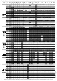
Ruderausschläge für Normalflug<br />
Querruder nach oben und unten 30 mm<br />
Höhenruder nach oben und unten.40 mm<br />
Seitenruder nach rechts und links 95 mm<br />
Es empfiehlt sich, senderseitig folgende Exponentialwerte einzustellen:<br />
Querruder 30%<br />
Höhenruder 30%<br />
Seitenruder 30%<br />
Wichtig:<br />
Bei der Montage der Gestänge grundsätzlich sorgfältig darauf achten, dass diese<br />
leicht laufen, ihren vollen steuerbaren Weg - einschließlich Trimmung - ausführen<br />
können und keinesfalls mechanisch begrenzt werden.<br />
Beim Bewegen des Steuerknüppels nach rechts, muss das Seitenruder nach rechts<br />
ausschlagen (links/links). Beim Bewegen des Höhen-/Tiefenruder-Knüppels nach<br />
hinten, sprich zum Bauch, müssen die Ruder nach oben ausschlagen (vorne = nach<br />
unten).<br />
Beim Bewegen des Querruder-Steuerknüppels nach rechts, muss das rechte<br />
Querruder nach oben, das linke nach unten ausschlagen. Beim Bewegen des<br />
Gasknüppels nach vorne, muss der Verbrennungsmotor in Vollgasstellung laufen,<br />
sprich der Vergaser muss ganz geöffnet sein. Bei Gasknüppel und Trimmung ganz<br />
hinten muss der Motor stehen bleibt.<br />
Nun bleibt nur noch viel Spaß und Freude beim Fliegen mit Ihrer EXTRA <strong>300</strong> HP zu<br />
wünschen.<br />
Ihr Team !<br />
GRAUPNER GmbH & Co. KG D-73230 KIRCHHEIM/TECK GERMANY<br />
Änderungen vorbehalten! Keine Haftung für Druckfehler 12/2007<br />
24
EXTRA <strong>300</strong> HP<br />
Instructions de montage<br />
Pour moteur à 4 temps jusqu’à 26 cm3<br />
Un ensemble R/C à 4 voies est nécessaire<br />
Réf. N° 9369<br />
9369.MX<br />
Caractéristiques techniques<br />
Envergure, env. 1700mm<br />
Longueur du fuselage, sans le cône, env. 1590mm<br />
Surface de l’aile, env. 55 dm²<br />
Surface du stabilisateur, env. 12 dm²<br />
Surface totale, env. 67 dm²<br />
Poids en ordre de vol, selon équipement, env. 4800 g.<br />
Différence de calage d’incidences 0 – 0,5°<br />
Centre de gravité, env. 100-110 mm mesurés derrière<br />
le bord d’attaque de l’aile.<br />
Attention: Ce modèle n'est pas un jouet!<br />
Si vous n'avez encore aucune expérience avec ce genre de modèle motorisé, faitesvous<br />
assister par un modéliste expérimenté. Ce modèle peut provoquer des<br />
blessures s'il est utilisé sans connaissances préalables. Pensez à la sécurité et à<br />
votre santé!<br />
Important! A lire avant de commencer la construction!<br />
Même si vous avez déjà construit de nombreux modèles R/C, veuillez lire<br />
attentivement ces instructions et vérifier si les pièces contenues dans cette boite de<br />
construction sont complètes. Beaucoup d'efforts ont été faits pour rendre la<br />
construction la plus simple possible, sans pour autant nuire à la sécurité.<br />
Conseils pour le film de recouvrement:<br />
En raison des fortes variations climatiques (Température, humidité, etc…) le<br />
recouvrement en film plastique peut présenter des petits plis. Ceci est du à la nature<br />
de la construction en bois avec ce genre de recouvrement. Il pourra être retendu à<br />
l'aide d'un séchoir électrique comme ceux utilisés en modélisme, en procédant<br />
comme suit:<br />
Plis : Chauffer le film et le frotter avec un chiffon doux.<br />
Aile déformée: Tordre légèrement l'aile dans le sens contraire à la déformation pour<br />
détendre le recouvrement et le retendre en appliquant l'air chaud.<br />
Précaution! Ne pas appliquer plus de chaleur que nécessaire. Un fer à repasser trop<br />
chaud fera fondre le film et il en résultera un trou!<br />
GRAUPNER GmbH & Co. KG D-73230 KIRCHHEIM/TECK GERMANY<br />
Änderungen vorbehalten! Keine Haftung für Druckfehler 12/2007<br />
25
Ce modèle largement préfabriqué ne nécessite encore que peu de temps pour sa<br />
finition. Mais les travaux restants sont importants et devront être effectués avec soin.<br />
De leur parfaite exécution dépendront la solidité finale prévue pour le modèle et ses<br />
performances de vol; c'est pourquoi il conviendra de travailler avec patience et<br />
précision!<br />
Lorsque des vis parker devront être filetées dans du bois, elles seront<br />
bloquées contre tout risque de desserrage avec de la colle blanche: injecter la<br />
colle dans le perçage et fileter la vis.<br />
Conseils de sécurité et avertissements concernant<br />
les modèles d'avions propulsés par un moteur thermique<br />
• Avant de tenter la première mise en service, la totalité des instructions de<br />
montage et d'utilisation devra être attentivement lue.<br />
• Ces conseils de sécurité font partie de ces instructions et devront être<br />
soigneusement conservés afin de pouvoir les remettre à l'utilisateur suivant<br />
en cas de vente du modèle.<br />
• Les modèles d'avions R/C sont des appareils pouvant être dangereux et qui<br />
exigent de leur utilisateur une grande compétence et la conscience de sa<br />
responsabilité.<br />
• Les modèles d’avions motorisés ne conviennent pas aux adolescents en<br />
dessous de 18 ans.<br />
• Leur utilisation doit se faire uniquement sous les instructions et la<br />
surveillance d'un adulte compétent et familiarisé avec les dangers qu'ils<br />
peuvent présenter.<br />
• L'utilisateur doit être en pleine possession de ses facultés physiques et<br />
mentales. Comme pour la conduite des automobiles, le pilotage d'un<br />
modèle réduit sous l'effet de l'alcool ou de la drogue n'est pas autorisé.<br />
• Les modèles volants R/C doivent être utilisés uniquement dans les<br />
conditions prévues par le fabricant, pour le sport et le loisir. Toute autre<br />
utilisation est interdite.<br />
• Un modèle volant ne peut évoluer correctement que s'il a été construit et<br />
réglé conformément aux instructions de montage. Des modifications dans<br />
la construction et dans les matériaux utilisés ne sont pas admissibles.<br />
Seule une utilisation prudente et responsable évitera de causer des<br />
dommages personnels et matériels. Personne ne peut prétendre prendre<br />
place dans un avion de tourisme et le piloter sans un apprentissage<br />
préalable. Il faut aussi apprendre à piloter un modèle réduit! Vous pouvez<br />
vous adresser pour cela à un modéliste expérimenté, vous inscrire dans un<br />
club d'aéromodélisme ou dans une école de pilotage. Vous pourrez en outre<br />
consulter votre revendeur ou la presse spécialisée sur le sujet.<br />
• Respectez scrupuleusement les indications données pour le centrage et les<br />
débattements de gouvernes! Le modèle devra être réglé en<br />
•<br />
correspondance.<br />
Ensemble R/C: Assurez-vous que la fréquence que vous utilisez est libre<br />
avant de mettre votre émetteur en contact!<br />
GRAUPNER GmbH & Co. KG D-73230 KIRCHHEIM/TECK GERMANY<br />
Änderungen vorbehalten! Keine Haftung für Druckfehler 12/2007<br />
26
• Vous êtes seul responsable de la sécurité d'utilisation de votre modèle et de<br />
son moteur.<br />
Si vous avez une question concernant l'utilisation de votre modèle et de<br />
son moteur, votre revendeur habituel vous renseignera volontiers.<br />
• Les hélices et en général toutes les pièces mécaniques entraînées par un<br />
moteur présentent un danger de blessures permanent et ne doivent être<br />
touchées par aucune partie du corps! Une hélice tournant à haut régime<br />
peut par ex. couper un doigt!<br />
• Ne vous tenez jamais dans le champ de rotation d'une hélice! Une pièce<br />
peut se détacher et être éjectée à haute vitesse avec une forte inertie et<br />
vous toucher, ou une tierce personne. Veillez également à ce qu'aucun<br />
objet quelconque vienne en contact avec l'hélice en rotation.<br />
• Veillez également aux vêtements flottants tels qu'écharpe ou cravate,<br />
etc…qui peuvent être aspirés et s'enrouler sur l'hélice.<br />
• Avant de faire voler votre modèle, informez tous les passants et les<br />
spectateurs sur les possibilités de danger qu'il peut présenter et demandezleur<br />
de se tenir à une distance de sécurité (au moins 5 mètres).<br />
• Un modèle volant R/C ne doit être utilisé que par des températures<br />
extérieures normales, c'est-à-dire dans une plage comprise entre –5° à +35°<br />
C. Les températures extrêmes peuvent conduire par ex. à une modification<br />
de la capacité des accus et des propriétés des matériaux.<br />
• Le carburant utilisé pour les moteurs modèle réduit est toxique! Ne le<br />
mettez pas en contact avec les yeux ou la bouche! Sa conservation devra se<br />
faire dans un récipient nettement identifiable et hors de la portée des<br />
enfants.<br />
• Ne faites jamais tourner un moteur thermique dans un local fermé, tels que<br />
cave, garage, etc…car les gaz d'échappement contiennent de l'oxyde de<br />
carbone dangereux.<br />
• Faites tourner votre moteur uniquement à l'extérieur!<br />
• Les colles et les peintures contiennent un solvant qui dans certaines<br />
circonstances peut être nocif pour la santé. Observez impérativement le<br />
mode d’emploi et les avertissements du fabricant correspondant.<br />
• Le carburant utilisé pour les modèles réduits est facilement inflammable et<br />
combustible, le tenir éloigné de toute flamme ouverte, d’une chaleur<br />
excessive et de toute source quelconque d’étincelles pouvant conduire à<br />
une inflammation. Ne fumez pas dans l’environnement direct du carburant<br />
ou de ses vapeurs.<br />
• Un moteur modèle réduit dégage une forte chaleur en fonctionnant. Le<br />
moteur et le silencieux deviennent très chauds et le restent encore un<br />
moment après l'arrêt. Ne les touchez pas dans ces conditions sous peine de<br />
vous brûler et prenez des précautions en effectuant les réglages! La chaleur<br />
du moteur peut aussi provoquer un incendie.<br />
• Durant le fonctionnement du moteur, l'échappement évacue non seulement<br />
des gaz chauds et toxiques, mais aussi des résidus de combustion<br />
également très chauds et liquides pouvant provoquer des brûlures.<br />
• Nettoyez le moteur après chaque utilisation. Vidangez le restant de<br />
carburant non consommé dans le réservoir et évacuez-le aussi du moteur.<br />
GRAUPNER GmbH & Co. KG D-73230 KIRCHHEIM/TECK GERMANY<br />
Änderungen vorbehalten! Keine Haftung für Druckfehler 12/2007<br />
27
• Avant chaque utilisation, vérifiez le modèle et toutes les pièces qui y sont<br />
rattachées (par ex. hélice, connexions des gouvernes, etc…) pour détecter<br />
une possible détérioration. Ce n'est qu'après avoir remédié à tous les<br />
défauts éventuels que le modèle pourra être mis en vol.<br />
• Le démarrage du moteur se fera avec un starter électrique. On pourra aussi<br />
le démarrer à la main en utilisant par ex. une pièce de bois rond recouvert<br />
d'un morceau de tuyau d'arrosage.<br />
• Les moteurs modèle réduits produisent en fonctionnement un bruit<br />
d'échappement pouvant être largement supérieur à 85 dB (A). Portez<br />
éventuellement des protège tympans. Ne faites jamais tourner un moteur<br />
sans silencieux. Même avec un silencieux, le bruit peut déranger le<br />
voisinage. Respectez les heures de repos.<br />
• L'hélice en rotation d'un modèle posé sur un sol sablonneux peut aspirer du<br />
sable ou de la poussière et vous la projeter dans les yeux. Portez des<br />
lunettes de protection!<br />
• Veillez à ce que le soquet à bougie ou son cordon, ni un autre objet posé<br />
sur le sol vienne en contact avec l'hélice en rotation.<br />
• Une précaution particulière est à prendre en transportant le modèle avec le<br />
moteur en marche; éloignez de vous l'hélice en rotation.<br />
• Veillez toujours à ce qu'il y ait une quantité suffisante de carburant dans le<br />
réservoir. La contenance du réservoir ne devra jamais être totalement vidée<br />
en<br />
• Ne survolez jamais de personnes.<br />
• Ne volez jamais en direction de personnes.<br />
• Tenez-vous à une distance suffisante des habitations; au moins à 1,5 Km à<br />
vol d'oiseau. Volez de préférence sur un terrain réservé à un club<br />
d'aéromodélisme. Tenez vous également à une distance de sécurité des<br />
lignes à haute tension.<br />
• Durant le décollage et le processus d'atterrissage, le terrain doit être libre<br />
de toute personne non autorisée et d'obstacle mobile.<br />
• Un modèle d'avion doit pouvoir être observé en permanence durant le vol<br />
pour éviter toute confusion avec d'autres modèles.<br />
• Ne faites jamais voler votre modèle sur des voies publiques, les places, les<br />
cours d'école, les parcs ou les aires de jeux, etc… et assurez-vous de l'avoir<br />
toujours sous votre contrôle.<br />
• Pour arrêter un moteur thermique en marche, le carburateur doit être réglé<br />
de façon à ce que l'admission d'air soit totalement fermée lorsque le<br />
manche des gaz et le levier de trim sont ramenés sur la position du ralenti.<br />
Si cela ne suffit pas, pincez la durit d'arrivée du carburant ou déconnectezla<br />
du carburateur. Ne tentez jamais d'arrêter le moteur en freinant l'hélice ou<br />
le cône avec la main!<br />
• Chaque modéliste doit se comporter de façon à ce que l'ordre et la sécurité<br />
publique, vis-à-vis des autres personnes et des biens, ainsi que l'activité<br />
des autres modélistes ne soient pas mis en danger, ni perturbés.<br />
• Un modèle réduit volant est comparable à un véritable aéronef pour lequel<br />
toutes les dispositions légales doivent être prises; la possession d'une<br />
assurance est obligatoire.<br />
GRAUPNER GmbH & Co. KG D-73230 KIRCHHEIM/TECK GERMANY<br />
Änderungen vorbehalten! Keine Haftung für Druckfehler 12/2007<br />
28
• Ces conseils mettent en évidence la diversité des dangers pouvant résulter<br />
d'une manipulation incorrecte et irresponsable. Leur observation permettra<br />
de pratiquer en toute sécurité ce loisir créatif et éducatif que représente<br />
l'aéromodélisme.<br />
Conseils de sécurité importants<br />
Vous avez fait l'acquisition d'une boite de construction avec les accessoires<br />
correspondants qui vont vous permettre la réalisation d'un modèle radiocommandé. Le<br />
respect des instructions de montage et d'utilisation relatives au modèle ainsi que<br />
l'installation, l'utilisation et l'entretien des éléments de son équipement ne peuvent pas<br />
être surveillés par la Firme GRAUPNER. C'est pourquoi nous déclinons toute<br />
responsabilité concernent les pertes, les dommages ou les coûts résultants d'une<br />
mauvaise utilisation ou d'un fonctionnement défectueux. Tant qu'elle n'y a pas été<br />
contrainte par le législateur, la responsabilité de la Firme GRAUPNER n'est<br />
aucunement engagée pour les dédommagements (incluant les dégâts personnels, les<br />
cas de décès, la détérioration de bâtiments ainsi que le remboursement des pertes<br />
commerciales dues à une interruption d'activité ou à la suite d'autres conséquences<br />
directes ou indirectes) provenant de l'utilisation du modèle. L'ensemble de sa<br />
responsabilité est en toutes circonstances et dans chaque cas strictement limité au<br />
montant que vous avez réellement payé pour ce modèle.<br />
L'utilisation du modèle se fait uniquement aux risques et périls de son<br />
utilisateur. Seule une utilisation prudente et responsable évitera de causer des<br />
dégâts personnels et matériels.<br />
Avant la première utilisation du modèle, vérifiez si votre assurance personnelle couvre<br />
ce genre de risques. Contractez le cas échéant une assurance spéciale pour<br />
l'utilisation des modèles réduits radiocommandés.<br />
En cas de revente du modèle, ces conseils de sécurité devront être impérativement<br />
remis à l'acheteur.<br />
Ce modèle largement préfabriqué ne nécessite encore que peu de temps pour sa<br />
finition. Mais les travaux restants sont importants et devront être effectués avec soin.<br />
De leur parfaite exécution dépendront la solidité finale prévue pour le modèle et ses<br />
performances de vol; c'est pourquoi il conviendra de travailler avec patience et<br />
précision!<br />
Conditions de garantie<br />
La garantie comprend la réparation gratuite ou l'échange des pièces présentant un<br />
défaut de fabrication ou de matière pendant une durée de 24 mois, à compter de la<br />
date de l'achat. Toutes autres réclamations sont exclues. Les frais de transport et<br />
d'emballage sont à la charge de l'acheteur. Nous déclinons toute responsabilité pour<br />
les détériorations survenues au cours du transport. Le retour au Service après vente<br />
GRAUPNER, ou du Pays concerné doit être accompagné d'une description du défaut<br />
constaté et de la facture correspondante avec la date de l'achat. Le bénéfice de la<br />
garantie sera perdu lorsque le défaut de la pièce ou du modèle sera dû à un<br />
accident, à une manipulation incorrecte ou à une mauvaise utilisation<br />
GRAUPNER GmbH & Co. KG D-73230 KIRCHHEIM/TECK GERMANY<br />
Änderungen vorbehalten! Keine Haftung für Druckfehler 12/2007<br />
29
Les points suivants devront être impérativement observés:<br />
� Avant de faire voler votre modèle, assurez-vous du parfait fonctionnement de<br />
l'installation R/C ainsi que du branchement correct et ferme de tous les<br />
connecteurs.<br />
� Les accus devront être rechargés et la portée de l'installation R/C devra être<br />
vérifiée. En particulier, les accus d'émission et de réception devront être<br />
rechargés avant chaque séance de vols.<br />
� Assurez-vous que la fréquence que vous utilisez est libre. Ne volez jamais<br />
lorsque vous n'êtes pas sûr qu’elle n’est pas déjà occupée.<br />
� Observez les conseils et les indications donnés dans les instructions d'utilisation<br />
de votre ensemble R/C et de ses accessoires.<br />
� Veillez à ce que les servos puissent se déplacer sur la totalité de leur course,<br />
sans limitation mécanique.<br />
� Les accus ne devront pas être mis en court-circuit.<br />
� Retirez tous les accus du modèle durant son transport et lorsqu'il n'est pas utilisé.<br />
� N'exposez pas le modèle à une trop forte humidité, à une chaleur ou un froid<br />
intensifs, ainsi qu'aux salissures.<br />
� Protégez le modèle et les éléments R/C contre tout risque de détérioration et de<br />
déplacement durant le transport<br />
Vérifications avant le départ<br />
Avant chaque utilisation, vérifiez le fonctionnement correct et la portée de l’installation<br />
R/C. Pour cela, mettez l’émetteur en contact et ensuite la réception. Ne déployez pas<br />
l’antenne télescopique de l’émetteur. A une certaine distance du modèle, vérifiez si<br />
toutes les gouvernes fonctionnent correctement et si elles débattent dans le bon sens.<br />
Répétez cette vérification avec le moteur en marche en faisant tenir le modèle par un<br />
aide.<br />
Pour les premiers essais d’un modèle volant, il est toujours préférable d’avoir un aide<br />
expérimenté à ses côtés qui effectuera les vérifications et assistera les premiers vols.<br />
Entretien:<br />
• Nettoyez le modèle après chaque utilisation. Nettoyez les salissures également<br />
sur l’hélice. Nettoyez le modèle et les éléments R/C avec un produit adapté;<br />
informez-vous pour cela auprès de votre revendeur.<br />
• Lorsque le modèle ne devra pas être utilisé pendant longtemps, toutes les pièces<br />
en mouvement devront être nettoyées et à nouveau lubrifiées.<br />
Conseils pour les assemblages du modèle<br />
� Veuillez lire et étudier les instructions de montage absolument jusqu'à la fin avant de<br />
commencer les assemblages du modèle.<br />
� Veillez aux dangers possibles avec l'utilisation des outils.<br />
� Nettoyer toute trace de gras avant d’effectuer les collages. Ceci pourra se faire<br />
par ex. par un ponçage suivi d’un nettoyage avec un solvant neutre. Ceci vaut<br />
également pour la préparation des surfaces pour la peinture afin d’obtenir une<br />
bonne adhérence de celle-ci. Avant d’effectuer le collage d’une pièce, poncer<br />
soigneusement la surface correspondante avec du papier abrasif fin<br />
(particulièrement avec les fuselages en fibre de verre) et la dégraisser ensuite,<br />
GRAUPNER GmbH & Co. KG D-73230 KIRCHHEIM/TECK GERMANY<br />
Änderungen vorbehalten! Keine Haftung für Druckfehler 12/2007<br />
30
par ex. avec de l’acétone. Autrement un collage suffisamment résistant ne pourra<br />
être garanti.<br />
Accessoires supplémentaires nécessaires<br />
Moteur et accessoires<br />
Moteur<br />
Réf. N°<br />
OS MAX 120 AX<br />
2703<br />
OS MAX FS 120 SURPASS<br />
1886<br />
OS MAX FT-160<br />
1412<br />
Cylindrée Silencieux Adaptateur Hélice<br />
cm³ Réf. N° Réf. N° Réf. N°<br />
20,0 2703.33 2703.36A 38 x 25 cm<br />
1318.38.25<br />
19,96 1886.33 - 36 x18 cm<br />
1316.36.18<br />
2x13,26 1431.80 avec - 38 x 20 cm<br />
3332.7 Coudes<br />
et<br />
1001.145 tubes<br />
flexibles<br />
(2 pces de<br />
chaque)<br />
1318.38.20<br />
Ensemble R/C:<br />
Il faut disposer d'au moins 4 voies et de 6 servos. L'émetteur devra en outre<br />
être équipé si possible d'un système d'inversion de course des servos.<br />
Les systèmes à micro-ordinateur à partir de mx-16 à mc-24 sont particulièrement<br />
conseillés. Des servos de dimensions normales pourront être utilisés (Par ex. Réf.<br />
N°3544).<br />
L'utilisation d'un accu de réception SAFT 4NH-<strong>300</strong>0 CS Best.-Nr.2566,4N-2200, est<br />
conseillée, lequel devra être bien entretenu avant et après chaque séance de vol,<br />
c'est-à-dire chargé plusieurs fois jusqu'à l'atteinte de la capacité indiquée, puis à<br />
nouveau déchargé.<br />
Pour le raccordement des servos d’ailerons et de profondeur avec le récepteur, un<br />
noyau en ferrite Réf. N°98516.1 sera nécessaire. Pour la liaison du cordon des<br />
servos d’ailerons avec le récepteur, il st conseillé de connecter sur les sorties de voie<br />
correspondantes (2 et 5) un cordon de rallonge Réf. N°3935.18. Les deux servos de<br />
profondeur seront munis chacun d’un cordon de rallonge Réf. N°3935.11 et les deux<br />
servos d’ailerons d’un cordon de rallonge Réf. N°3935.18.<br />
Du caoutchouc mousse pour l’enrobage du récepteur et de l’accu de réception est<br />
fourni.<br />
Colles<br />
Colle epoxy, par ex. UHU plus schnellfest, réf. N°962<br />
Colle epoxy, par ex. UHU plus endfest, Réf. N°950<br />
Colle blanche, par ex. UHU coll, Réf. N°958.60<br />
UHU hart, par ex. Réf. N°534<br />
UHU ALLESKLEBER Kraft,, par ex. Réf. N°1096<br />
Colle seconde, par ex. Réf. N°5821<br />
Freine filet UHU, par ex. Réf. N°952<br />
Accessoires de terrain (Non fournis):<br />
Carburant avec huile synthétique, selon le moteur utilisé<br />
GRAUPNER GmbH & Co. KG D-73230 KIRCHHEIM/TECK GERMANY<br />
Änderungen vorbehalten! Keine Haftung für Druckfehler 12/2007<br />
31
Filtre à carburant, par ex. Réf. N°1650.1<br />
Durit à carburant, par ex. Réf. N°1643 pour les moteurs à méthanol<br />
Durit à carburant, par ex. Réf. N°1325.2 pour les moteurs à essence<br />
Pompe à carburant à main, par ex. Réf. N°1610 ou 6870<br />
Réservoir de volige, par ex. 136<br />
Batterie de démarrage avec soquet à bougie, par ex. Réf. N° 3247<br />
Starter électrique, par ex. Réf. N°1628<br />
Batterie de starter, par ex. Réf. N°2592<br />
Outillage nécessaire (Non fourni):<br />
Différents tournevis (Cruciformes), des pinces à becs pointus, des pinces plates, des<br />
pinces coupantes, un couteau à balsa ou une lame de rasoir, un jeu de forets, une<br />
clé à bougie universelle, un crayon ou un feutre et un fer à souder avec une panne<br />
fine.<br />
Les assemblages de l’EXTRA <strong>300</strong> HP<br />
Commencer les assemblages lorsque vous serez d'abord familiarisé avec les pièces<br />
et les différents stades de montage. Si l'une des pièces fait l'objet d'une réclamation,<br />
consultez votre revendeur de même avant de commencer les assemblages.<br />
Tâter avec les doigts les ouvertures dans le fuselage pour les servos de profondeur<br />
et découper le film de recouvrement avec la panne d’un fer à souder chaud.<br />
Le plan fixe de la dérive sera maintenant collé en place. Pour cela, le film de<br />
recouvrement sera retiré sur la surface d’appui du fuselage et sur le plan fixe, comme<br />
montré sur la photo.<br />
Enduire la surface de collage de colle (Colle à bois express UHU) et le plan fixe sera<br />
posé sur le fuselage de façon à ce que la languette à l’avant s’engage dans<br />
l’ouverture du couple et qu’il repose à plat sur le fuselage. Fixer le plan fixe jusqu’à la<br />
prise de la colle avec du ruban adhésif.<br />
Fixer les jambes du train d’atterrissage sous le fuselage avec les vis fournies en les<br />
bloquant avec du freine filet UHU.<br />
Ajuster les pantalons des jambes au fuselage et les coller avec de la UHU<br />
Alleskleber Kraft.<br />
Tracer la position du perçage pour les axes sur les carénages de roue, comme<br />
montré sur la photo. Positionner les renforts en bois de façon à ce que le perçage<br />
soit pratiqué au milieu du passage de la roue et à env. 12mm au dessus du bord<br />
inférieur du carénage, comme montré sur la photo. .<br />
Percer les carénages de roue à l’intérieur et à l’extérieur avec un foret de Ø 4 mm au<br />
centre du repère tracé.<br />
Coller les renforts en bois sur le côté intérieur des carénages de roue avec de la colle<br />
seconde ; veiller a réaliser un carénage gauche et un droit.<br />
Fixer les renforts en bois au moyen des axes de roue jusqu’à la prise de la colle.<br />
GRAUPNER GmbH & Co. KG D-73230 KIRCHHEIM/TECK GERMANY<br />
Änderungen vorbehalten! Keine Haftung für Druckfehler 12/2007<br />
32
Agrandir le perçage à l’intérieur des carénages de roue à Ø 8 mm et les ouvrir vers le<br />
bas pour l’introduction des axes de roue.<br />
Monter les axes de roue pour marquer leur longueur, comme montré sur la photo et<br />
les couper.<br />
Les carénages seront maintenant montés ensemble avec les axes de roue sur les<br />
jambes du train d’atterrissage ; les écrous devront être bloqués avec du freine filet<br />
UHU.<br />
Insérer les passe fils en caoutchouc et les oeillets dans les pattes des servos,<br />
comme montré sur la photo.<br />
Rallonger le cordon des servos avec les cordons de rallonge correspondants. Fixer<br />
les connecteurs avec quelques gouttes de colle seconde, ou avec un morceau de<br />
gaine thermo rétractable<br />
Modifier les palonniers comme montré sur la photo et les monter sur les<br />
servos réglés en position neutre.<br />
Percer les avant trous de Ø 1,5 mm dans les panneaux d’aile pour la fixation des<br />
servos d’ailerons. Enfiler les cordons de raccordement au travers des ouvertures<br />
dans les nervures, jusqu’à la nervure d’emplanture.<br />
Pour le collage des charnières, tracer le milieu de celles-ci avec un crayon.<br />
Les charnières seront maintenant collées dans les gouvernes jusqu’au trait de<br />
crayon ; de la colle seconde fluide pourra être utilisée. Introduire les charnière sur<br />
env. 1mm de profondeur dans les encastrements, appliquer deux gouttes de colle<br />
seconde les deus faces des charnières et les pousser dans les encastrements<br />
jusqu’au trait de crayon.<br />
Après la prise de la colle, introduire les charnières des gouvernes dans l’aile et dans<br />
les plans fixes du stabilisateur et de la dérive (sur env. 1mm de profondeur).<br />
Appliquer de la colle seconde fluide sur les charnière et les pousser dans les<br />
encastrements, comme il a été précédemment décrit et de façon à ce qu’il subsiste<br />
un espace d’env. 0,5mm entre les pièces.<br />
Après la prise de la colle, monter les guignols de gouverne. Pour cela, des trous de<br />
Ø 6 mm devront être percés à l’emplacement marqué sur les gouvernes.<br />
Retirer le film de recouvrement sur les gouvernes en correspondance de la surface<br />
d’appui des douilles taraudées en aluminium. Remplir les perçages de colle et y<br />
insérer les douilles en aluminium, puis essuyer les bavures de colle.<br />
Courber vers l’avant les deux vis M3 sur la gouverne de direction, comme montré sur<br />
la photo.<br />
Visser les pattes de connexion sur les vis M3 sur les gouvernes de profondeur et<br />
d’ailerons de façon à ce que le point de connexion se trouve à env. 19mm au dessus<br />
de la surface de la gouverne.<br />
GRAUPNER GmbH & Co. KG D-73230 KIRCHHEIM/TECK GERMANY<br />
Änderungen vorbehalten! Keine Haftung für Druckfehler 12/2007<br />
33
Couper la longueur excédentaire des vis avec des pinces coupantes et les limer au<br />
ras de la patte de connexion.<br />
Confectionner maintenant les tringleries d’ailerons.<br />
Pour chaque tringlerie, mesurer la distance entre le trou de connexion sur le<br />
palonnier du servo et celui sur la patte de connexion et couper une longueur<br />
correspondante dans la tringlerie filetée M3, puis visser dessus une chape et un<br />
contre écrou. La connecter ensuite sur le palonnier du servo et sur la patte de<br />
connexion et la régler de façon à ce que le servo et la gouverne se trouvent en<br />
position neutre.<br />
Les plans fixes du stabilisateur seront maintenant collés contre le fuselage au moyen<br />
du tube en aluminium. Pour cela et comme déjà décrit pour le plan fixe de la dérive,<br />
le film de recouvrement sera retiré sur la nervure d’emplanture des deux plans fixes.<br />
Introduire le tube de jonction au travers des perçages dans le fuselage de façon à ce<br />
qu’il dépasse sur une longueur égale de chaque côté. Enduire la nervure<br />
d’emplanture des deux plans fixes (Colle à bois express UHU) et les pousser ensuite<br />
bien serrés contre le fuselage, puis essuyer les bavures de colle.<br />
L’étape de travail suivante consistera au montage de la roulette de queue. Pour cela,<br />
tâter l’emplacement des deus trous de fixation sur le fond du fuselage et dégager le<br />
film de recouvrement. Fixer la roulette de queue sous le fuselage au moyen des deux<br />
vis M3.<br />
Afin que l’orientation de la roulette de queue soit entraînée par la gouverne de<br />
direction, connecter les deux ressorts de traction fournis entre les guignols de la<br />
gouverne et la roulette de queue, comme montré sur la photo.<br />
Monter ensuite les câbles de commande de la gouverne de direction et les deux<br />
tringleries de profondeur, comme montré sur la photo.<br />
Comme il a déjà été décrit pour celles des ailerons, mesurer la longueur nécessaire<br />
pour les deux tringleries de profondeur et les visser ensemble. Pour la commande de<br />
la gouverne de direction, les câbles seront d‘abord connectés sur celle-ci au moyen<br />
des douilles de sertissage. Connecter les chapes sur le palonnier du servo, introduire<br />
les câbles dans le perçage des vis à œillet, les tendre et les fixer de même avec les<br />
douilles de sertissage. Le réglage précis des câbles se fera en vissant ou en<br />
dévissant les chapes sur les douilles filetées<br />
Assemblage et montage du réservoir<br />
Connecter une longueur de durit silicone sur le plongeur du réservoir ; couper sa<br />
longueur de façon à ce que le plongeur puisse se mouvoir sans se bloquer à<br />
l’intérieur du réservoir lorsque le bouchon sera monté. Chauffer légèrement les tubes<br />
en plastique libres avec un séchoir électrique ou un briquet pour pouvoir les courber<br />
facilement. L’un des tubes sera orienté vers le bas pour le remplissage ultérieur du<br />
réservoir et l’autre vers le haut pour servir de trop plein. Prolonger les deux tubes<br />
avec une longueur de durit silicone de façon à ce qu’ils atteignent le haut et le bas du<br />
réservoir.<br />
GRAUPNER GmbH & Co. KG D-73230 KIRCHHEIM/TECK GERMANY<br />
Änderungen vorbehalten! Keine Haftung für Druckfehler 12/2007<br />
34
Monter maintenant le bouchon du réservoir et le bloquer avec la vis à tête cruciforme.<br />
Il est important que la vis soit suffisamment serrée afin que le réservoir soit étanche.<br />
Ceci pourra être contrôlé en plongeant le réservoir rempli d’air dans de l’eau ; le<br />
réservoir est étanche lorsque aucune bulle d’air ne monte à la surface.<br />
Connecter une longueur de durit silicone sur chaque tube sortant du réservoir.<br />
Repérer maintenant les trois durits (Alimentation, remplissage et trop-plein) avec un<br />
crayon feutre<br />
Introduire maintenant le réservoir par l’ouverture dans le fuselage de façon à ce que<br />
les trois durits silicone passent au travers de l’ouverture dans le couple avant.<br />
Connecter la durit silicone venant du plongeur sur la prise du carburateur, faire<br />
passer celle du trop plein vers le bas, la durit pour le remplissage pourra sortir<br />
ultérieurement vers l’extérieur par un trou percé dans le capot moteur. Le risque de<br />
glissement du réservoir vers l’arrière sera empêché par la tension d’une bande<br />
élastique.<br />
Montage du moteur thermique<br />
Le moteur sera fixé sur les deux bras du bâti de façon à obtenir une distance d’env.<br />
152mm mesurée entre le plateau d’hélice et la face arrière du bâti. Percer les trous<br />
de fixation dans les bras du bâti et fixer le moteur avec les vis fournies en les<br />
bloquant avec du freine filet UHU.<br />
Le bâti moteur sera fixé sur le couple avant de façon à ce que son milieu<br />
corresponde avec celui du marquage sur le couple. Reporter les trous de fixation sur<br />
celui-ci et les percer en correspondance des écrous spéciaux. Avec l’utilisation du<br />
moteur OS MAX 120 AX, les trous de fixation sont déjà percés et les écrous spéciaux<br />
sont insérés. Ceci est adapté bien entendu pour d’autres moteurs avec la même<br />
largeur de carter.<br />
Fixer le bâti moteur en bloquant les vis avec du freine filet UHU.<br />
Reporter maintenant le perçage sur le couple avant pour le passage de la tringlerie<br />
de gaz et le pratiquer.<br />
Le levier du carburateur devra être démonté pour le montage de la tringlerie de gaz.<br />
Connecter le contre coudage de la tringlerie sur le levier du carburateur et l’introduire<br />
avec la gaine de guidage au travers du perçage dans le couple avant et dans le<br />
couple devant le fourreau de jonction d’aile. La tringlerie devra traverser en même<br />
temps le perçage transversal du raccord de tringlerie qui devra déjà être monté sur le<br />
palonnier de servo de gaz.<br />
La tringlerie de gaz sera fixée dans le raccord de tringlerie avec le servo de gaz en<br />
position milieu et le carburateur à demi ouvert ; bloquer la vis pointeau avec du freine<br />
filet UHU. Le servo sera ultérieurement programmé de façon à ce que le moteur<br />
s’arrête avec le manche des gaz sur la position du ralenti et le levier de trim tiré<br />
entièrement vers l’arrière.<br />
Monter le silencieux sur le moteur avec l’adaptateur fourni.<br />
Un bras du bâti moteur devra être évidé pour le raccordement de la pressurisation<br />
GRAUPNER GmbH & Co. KG D-73230 KIRCHHEIM/TECK GERMANY<br />
Änderungen vorbehalten! Keine Haftung für Druckfehler 12/2007<br />
35
Les quatre petits blocs seront collés sur le couple avant pour la fixation du capot<br />
moteur.<br />
Les points de fixation devront être marqués sur le fuselage pour le montage du capot<br />
moteur. Ces points seront marqués vers l’arrière à l’extérieur du capot moteur par le<br />
collage d’une bande crêpe adhésive. Lorsque le capot moteur sera maintenant mis<br />
en place sur le fuselage, les points de fixation seront reportés sur celui-ci.<br />
En mettant en place le capot moteur, veiller à ce que le formage pour le cône d’hélice<br />
corresponde avec l’embase de ce dernier. Le capot sera fixé de façon à ce qu’il<br />
subsiste un espace d’env. 1,5mm entre l’embase du cône et son bord avant.<br />
Des ouvertures correspondantes seront pratiquées dans le capot moteur pour le<br />
passage de la culasse, de la bougie, du silencieux, du pointeau, etc… selon le<br />
moteur utilisé.<br />
L’interrupteur de la réception pourra être monté sur le flanc droit ou gauche du<br />
fuselage. Retirer le film de recouvrement pour fixer l’interrupteur, selon celui utilisé.<br />
Assemblage de l’EXTRA <strong>300</strong> HP<br />
Pour le raccordement des deux servos d’ailerons sur le récepteur, il est conseillé de<br />
connecter un cordon de rallonge de 180mm de longueur sur les sorties de voie<br />
correspondantes (2 et 5).<br />
Introduire le tube de jonction d‘aile en aluminium, glisser dessus les panneaux d’aile<br />
et les serrer contre le fuselage avec les quatre vis en plastique. Serrer juste<br />
suffisamment les vis pour que les panneaux d’aile soient bien immobilisée contre le<br />
fuselage.<br />
Relier les servos d’ailerons aux cordons de rallonge.<br />
Les vis pourront être raccourcies sur env. 20mm.<br />
Centrage de l’EXTRA <strong>300</strong> HP<br />
Soutenir le modèle sous l’aile, de chaque côté du fuselage, avec le réservoir vide, sur<br />
un point située à env. 100 - 110 derrière le bord d’attaque de l’aile. Avec un centrage<br />
correct, le modèle doit se tenir en équilibre sur ce point, le nez penchant légèrement<br />
vers le bas. Le centrage correct sera obtenu si nécessaire par le déplacement de<br />
l’accu de réception ou par le collage d’un lest en plomb. Avant le premier vol, toutes<br />
les gouvernes devront être réglées exactement en position neutre avec les trims sur<br />
l’émetteur<br />
Débattements des gouvernes pour le vol normal<br />
Ailerons 30mm vers le haut et vers le bas<br />
Profondeur 40mm vers le haut et vers le bas<br />
Direction 95mm vers la droite et vers la gauche<br />
Il est conseillé de régler les valeurs suivantes d’exponentiel dans l’émetteur :<br />
Ailerons 30%<br />
Profondeur 30%<br />
Direction 30%<br />
GRAUPNER GmbH & Co. KG D-73230 KIRCHHEIM/TECK GERMANY<br />
Änderungen vorbehalten! Keine Haftung für Druckfehler 12/2007<br />
36
Important<br />
Lors du montage des tringleries, veillez à ce qu’elles puissent se mouvoir librement<br />
sur toute la course du servo, incluant le trim, sans être limitées mécaniquement.<br />
En déplaçant le manche de commande de direction vers la droite, la gouverne de<br />
direction doit se braquer vers la droite (et vers la gauche, à gauche). En tirant le<br />
manche de commande de profondeur vers l’arrière (à soi), la gouverne de profondeur<br />
soit se soulever (et en la poussant vers l’avant, s’abaisser). En déplaçant le manche<br />
de commande des ailerons vers la droite, le volet droit doit se soulever et le gauche<br />
s’abaisser. En poussant le manche de commande des gaz en avant, le moteur doit<br />
tourner à plein gaz avec le carburateur entièrement ouvert et en le tirant en arrière, il<br />
doit tourner au ralenti. En tirant le levier de trim totalement vers l’arrière, le moteur<br />
doit s’arrêter.<br />
Il nous reste maintenant à vous souhaiter beaucoup de plaisir avec les vols de votre<br />
EXTRA <strong>300</strong> S !<br />
Votre équipe <strong>Graupner</strong> !<br />
GRAUPNER GmbH & Co. KG D-73230 KIRCHHEIM/TECK GERMANY<br />
Änderungen vorbehalten! Keine Haftung für Druckfehler 12/2007<br />
37
Instructions<br />
EXTRA <strong>300</strong> HP<br />
For two-stroke engines of around 26 cc capacity<br />
The model requires a four-channel radio control system<br />
Order No.9369<br />
9369.MX<br />
Specification<br />
Wingspan approx. 1700 mm<br />
Fuselage length excl. spinner approx. 1590 mm<br />
Wing area approx. 55 dm²<br />
Tailplane area approx. 12 dm²<br />
Total surface area approx. 67 dm²<br />
All-up weight according to fittings approx. 4800 g<br />
Longitudinal dihedral 0 - 0.5°<br />
Centre of Gravity approx. 100 - 110 mm aft of the root leading edge,<br />
measured on both sides of the fuselage<br />
Caution: this model is not a toy!<br />
If you are a beginner to this type of powered model, please ask an experienced<br />
model flyer for help and support. If you attempt to operate the model without knowing<br />
what you are doing, you could easily injure yourself or somebody else. Please keep<br />
your safety and well-being in mind at all times.<br />
Important: before you start construction<br />
Even if you have already built a large number of RC models please read right through<br />
these instructions and check that all the kit components are actually present. We<br />
have taken great trouble to keep construction as simple as possible, without making<br />
any compromises in the area of safety.<br />
Note regarding the film covering<br />
Minor creases or bubbles may develop in the film covering due to major fluctuations<br />
in weather conditions (temperature, humidity etc.); in rare cases you may even find a<br />
slight warp in a component. These minor faults are in the nature of film-covered builtup<br />
wooden structures, and can easily be corrected using a heat gun, as commonly<br />
used for modelling.<br />
GRAUPNER GmbH & Co. KG D-73230 KIRCHHEIM/TECK GERMANY<br />
Änderungen vorbehalten! Keine Haftung für Druckfehler 12/2007<br />
38
Creases: Blow warm air over the area and rub down with a soft cloth.<br />
Wing warp: Hold the panel twisted gently in the opposite direction to the warp,<br />
and apply warm air to remove the creases from the covering.<br />
Caution! Do not heat the film more than is absolutely necessary. If the air or the iron<br />
is too hot, the film may melt and holes may be formed.<br />
This model is highly pre-fabricated and can be built in a very short time. However, the<br />
work which you have to carry out is important and must be done carefully. The model<br />
will only be strong and fly well if you complete your tasks competently - so please<br />
work slowly and accurately.<br />
When self-tapping screws have to be screwed into wood, apply a little white<br />
glue to prevent them shaking loose: just squirt white glue into the hole and fit<br />
the screw.<br />
Safety notes and warnings relating to model aircraft<br />
powered by glowplug motors and petrol engines<br />
• Be sure to read right through the instructions covering assembly and<br />
operation of your model before you attempt to operate it for the first time.<br />
• These safety notes are an integral part of the instructions. Please keep<br />
them and the operating instructions in a safe place. If you ever dispose of<br />
the model be sure to pass them on to the new owner.<br />
• Powered model aircraft are very demanding and potentially dangerous<br />
machines, and call for a high level of technical knowledge and skill from<br />
the operator, together with a responsible attitude.<br />
• Powered model aircraft are not suitable for young persons under 18 years<br />
of age.<br />
• Young people should only be permitted to operate this model under the<br />
instruction and supervision of an adult who is aware of the hazards<br />
involved in this activity.<br />
• The operator of the model must be in full possession of his or her bodily<br />
and mental faculties. As with car driving, operating a model aircraft under<br />
the influence of alcohol or drugs is not permissible under any<br />
circumstances.<br />
• Radio-controlled model aircraft may only be employed for the purpose<br />
intended by the manufacturer. They must never be used as man-carrying<br />
machines. We do not permit this model’s use in any way except as a model<br />
aircraft.<br />
• A radio-controlled model aircraft can only work properly and fulfil your<br />
expectations if it is built very carefully and in accordance with the building<br />
instructions. Do not make any modifications of any kind to the design<br />
features or materials. If you wish to avoid injuring people and damaging<br />
property it is essential to be careful and painstaking at all stages of<br />
building and operating your model. Nobody would climb into a full-size<br />
light aircraft and try to fly it without completing a course of training first.<br />
Model flying is a skill which has to be learned in just the same way. We<br />
GRAUPNER GmbH & Co. KG D-73230 KIRCHHEIM/TECK GERMANY<br />
Änderungen vorbehalten! Keine Haftung für Druckfehler 12/2007<br />
39
suggest that you ask for help from an experienced model flyer, or join a<br />
model club or flight training school. Your local model shop and the<br />
specialist magazines are excellent sources of information.<br />
• It is fundamentally essential to set the Centre of Gravity (CG) and control<br />
surface travels correctly. Adjust the model until they are exactly correct.<br />
• Radio control system: satisfy yourself that your frequency is vacant before<br />
you switch on. Check your RC system regularly as its components<br />
eventually wear and need to be replaced or repaired. Radio interference<br />
caused by unknown sources can occur at any time without warning. If this<br />
should happen, your model will be uncontrollable and completely<br />
unpredictable. Never leave your radio control system unguarded, as other<br />
people might pick it up and try to use it. Your RC system can only work<br />
reliably if the batteries are kept fully charged.<br />
• Don’t ignore our warnings. They refer to materials and situations which, if<br />
ignored, can result in fatal injury or permanent damage.<br />
• You alone are responsible for the safe operation of your radio-controlled<br />
model aircraft and motor.<br />
• If you have any questions regarding the safe operation of your RC model<br />
aircraft, please turn to your local model shop in the first instance as the<br />
staff will be pleased to help you.<br />
• Propellers and other rotating parts which are powered by a motor represent<br />
a permanent hazard and present a real risk of injury. Don’t touch them with<br />
any part of your body. For example, a propeller spinning at high speed can<br />
easily slice off a finger.<br />
• Keep well clear of the rotational plane of the propeller. You never know<br />
when some part may come loose and fly off at high speed, hitting you or<br />
anybody else in the vicinity. Never touch the revolving propeller with any<br />
object.<br />
• Take care with loose clothing such as scarves, loose shirts etc. Flapping<br />
cloth can easily be sucked into the area of the propeller and then get<br />
tangled in the blades. This is extremely dangerous.<br />
• If there are passers-by or spectators at your flying site, make sure that they<br />
are aware of the dangers inherent in your activity, and insist that they keep<br />
a safe distance away (at least 5 m).<br />
• Radio-controlled models should only be flown in “normal” weather<br />
conditions, i.e. a temperature range of -5° to +35° C. More extreme<br />
temperatures can lead to changes in battery capacity, material<br />
characteristics and other unwanted effects.<br />
• Model fuels are toxic; do not allow them to come into contact with your<br />
eyes or mouth. Fuel should always be stored in clearly marked containers,<br />
out of the reach of children.<br />
• Never run an internal combustion engine in an enclosed space such as a<br />
cellar, garage etc. Model motors produce lethal carbon monoxide gas just<br />
like full-size engines.<br />
• Motors should only be run in the open air!<br />
• Adhesives and paints contain solvents which may be hazardous to health<br />
under certain circumstances. Read and observe the notes and warnings<br />
supplied by the manufacturer of these materials.<br />
GRAUPNER GmbH & Co. KG D-73230 KIRCHHEIM/TECK GERMANY<br />
Änderungen vorbehalten! Keine Haftung für Druckfehler 12/2007<br />
40
• Model fuels are volatile and highly inflammable. Keep them well away from<br />
open flames, excessive heat, all possible sources of sparks and anything<br />
else which could result in a fire. Do not smoke in the immediate vicinity of<br />
fuel or fuel vapours.<br />
• Model engines generate a lot of heat. The motor and silencer in particular<br />
become very hot when running, and stay at a high temperature for quite a<br />
while. Touching the hot parts can give you serious burns, so take care<br />
especially when carrying out adjustments - wear protective gloves. Hot<br />
engines can even start a fire under certain circumstances.<br />
• When the motor is running it expels hot toxic gases from the exhaust<br />
together with very hot fluid combustion residues which can burn you if you<br />
are not careful.<br />
• Remove all unused fuel from the fueltank and motor after every session.<br />
• Every time you intend to operate your model check carefully that it and<br />
everything attached to it (e.g. propeller, linkages, control surfaces etc.) is in<br />
good condition and undamaged. If you find a fault, do not fly the model<br />
until you have corrected it.<br />
• Model engines are usually started with the help of an electric starter which<br />
should be fitted with the appropriate adaptor where necessary. With fixedwing<br />
models an alternative is to use a “chicken stick” - a length of thick<br />
wooden dowel with a piece of water hose pushed over it.<br />
• Many model motors are very noisy, producing a sound level much higher<br />
than 85 dB (A), which implies that you should wear ear defenders. Never<br />
run a motor without the silencer fitted. Even with a silencer, model engines<br />
can easily disturb your neighbours. Don’t run engines when other people<br />
expect peace and quiet.<br />
• If you start your motor when the model is standing on loose or sandy<br />
ground, the propeller will suck up sand and dust and hurl it around, and it<br />
could easily get in your eyes and do damage. Wear protective goggles at<br />
such times.<br />
• Take care that the glowplug clip and the glow lead cannot get tangled in the<br />
propeller or other rotating parts. Check the throttle linkage too.<br />
• Take particular care when carrying the model with the motor running. Hold<br />
the rotating parts well away from you!<br />
• Be sure to keep an adequate supply of fuel in the tank. Don’t continue to fly<br />
the model until the tank is drained dry.<br />
• Never fly directly over people.<br />
• Never fly directly towards people.<br />
• Keep a safe distance from residential areas: at least 1.5 km “as the crow<br />
flies”. The best solution is to join a model flying club and use the approved<br />
flying site. Always keep well clear of high-tension overhead cables.<br />
• Whenever you are working on the motor, make sure that you are on a safe<br />
surface and cannot slip. Get used to holding the model really securely.<br />
• Take-off and landing strips should be kept free of unauthorised people and<br />
movable obstacles, particularly when a model is using the strip.<br />
• Watch the aeroplane constantly while it is in the air. Models must always<br />
give way to full-size aircraft.<br />
GRAUPNER GmbH & Co. KG D-73230 KIRCHHEIM/TECK GERMANY<br />
Änderungen vorbehalten! Keine Haftung für Druckfehler 12/2007<br />
41
• Don’t operate your aircraft from public roads, squares, school playgrounds,<br />
public parks or sports grounds etc., and ensure that you are always in full<br />
control of the model.<br />
• It is important that you are able to stop your engine at any time. This is<br />
achieved by adjusting the throttle so that the barrel closes completely<br />
when you move the throttle stick and trim to their end-points. If this does<br />
not work, pinch the fuel feed line between your fingers or pull it off the<br />
carburettor. Never try to stop the motor by grasping the flywheel, propeller<br />
or spinner!<br />
• All model flyers should behave in a manner which minimises the danger to<br />
people and property. Never act in any way which will disturb other flyers<br />
and jeopardise safe, orderly flying at the site.<br />
• In legal terms our models are classed as aircraft, and as such are subject to<br />
legal regulations and restrictions which must be observed.<br />
• Our brochure “Modellflugrecht, Paragrafen und mehr” (Model Aviation Law,<br />
Legal Requirements and more) is available under Order No. 8034.02, and<br />
contains a summary of all these rules. Your local model shop should have<br />
a copy which you can read. Models fitted with glowplug motors may only<br />
be flown with the landowner’s permission, and third party insurance is<br />
mandatory. There are also Post Office regulations concerning your radio<br />
control system, and these must be observed at all times.<br />
• Please don’t misunderstand the purpose of these notes. We only want to<br />
make you aware of the many dangers and hazards which can arise if you<br />
lack knowledge and experience, or work carelessly or irresponsibly. If you<br />
take reasonable care, model flying is a highly creative, instructive,<br />
enjoyable and relaxing pastime.<br />
• This model is highly pre-fabricated and can be built in a very short time.<br />
However, the work which you have to carry out is important and must be<br />
done carefully. The model will only be strong and fly well if you complete<br />
your tasks competently - so please work slowly and accurately.<br />
Important safety notes<br />
You have acquired a kit which can be assembled into a fully working RC model when<br />
fitted out with suitable accessories. However, we, as manufacturers, have no control<br />
over the way you build and operate your RC model aircraft, nor how you install,<br />
operate and maintain the associated components, and for this reason we are obliged<br />
to deny all liability for loss, damage or costs which are incurred due to the<br />
incompetent or incorrect use and operation of our products, or which are connected<br />
with such operation in any way. Unless otherwise prescribed by binding law, the<br />
obligation of the GRAUPNER company to pay compensation, regardless of the legal<br />
argument employed, is excluded. This includes personal injury, death, damage to<br />
buildings, damage due to loss of business or turnover, interruption of business or<br />
other direct or indirect consequent damage whose root cause was the operation of<br />
the model.<br />
The total liability in all cases is limited to the amount of money which you actually<br />
paid for the model.<br />
GRAUPNER GmbH & Co. KG D-73230 KIRCHHEIM/TECK GERMANY<br />
Änderungen vorbehalten! Keine Haftung für Druckfehler 12/2007<br />
42
This model is built and flown at the sole and express responsibility of the<br />
operator. The only way to avoid injury to persons and damage to property is to<br />
handle and operate the model with the greatest care and consideration at all<br />
times.<br />
Before you operate the model for the first time, please check that your private thirdparty<br />
liability insurance policy covers you for the operation of models of this type. If<br />
you are not sure, take out a special policy designed to cover modelling risks.<br />
These safety notes must be kept in a safe place. If you ever dispose of the model, be<br />
sure to pass them on to the new owner.<br />
Guarantee conditions<br />
The guarantee covers replacement of any parts which can be shown to exhibit<br />
manufacturing faults or material defects within the guarantee period of 24<br />
months from the initial date of purchase. No other claims will be considered.<br />
Cost of transport, packing and freight are payable by the purchaser. We accept<br />
no liability for damage in transit. When you send the product to GRAUPNER, or<br />
to the approved Service Centre for your country, you must include a clear and<br />
concise description of the fault together with the invoice showing the date of<br />
purchase. The guarantee is invalid if the component or model fails due to an<br />
accident, incompetent handling or incorrect usage.<br />
The following points are important and must be observed at all times:<br />
• Before you fly the model, check that the radio control system is working reliably,<br />
and that all connections are secure.<br />
• The batteries must be charged and the range of the radio control system must be<br />
checked before you operate the model. In particular, the radio control system<br />
batteries must be fully charged before each session and checked before each<br />
flight.<br />
• Ensure that the channel you intend to use is not already in use by other<br />
modellers. Never fly the model if you are not certain that your channel is free.<br />
• Read and observe the instructions and recommendations provided by the<br />
manufacturer of your radio control system and accessory components.<br />
• Ensure that the servos are not mechanically obstructed at any point in their travel.<br />
• Dry cells and rechargeable batteries must never be short-circuited.<br />
• Remove all batteries from the model prior to transporting and storing it.<br />
• Do not subject the model to dirty or cold conditions, or high levels of humidity or<br />
heat.<br />
• Secure the model and your RC equipment carefully when transporting them. They<br />
may be seriously damaged if they are free to slide about.<br />
Pre-flight checks<br />
Check that the radio control system is working correctly and at full range before every<br />
flight: fit the transmitter aerial and extend it fully, then switch on the transmitter and<br />
the receiving system. Walk away from the model, and check that all the control<br />
surfaces work smoothly and immediately at an appropriate distance, and deflect in<br />
the correct “sense” (direction) relative to the stick movements.<br />
GRAUPNER GmbH & Co. KG D-73230 KIRCHHEIM/TECK GERMANY<br />
Änderungen vorbehalten! Keine Haftung für Druckfehler 12/2007<br />
43
Repeat the check with the engine running while a friend holds the model securely for<br />
you.<br />
If you are a relative beginner to model flying, we recommend that you enlist the aid of<br />
an experienced model pilot to help you check and test-fly the model.<br />
Care and maintenance<br />
• Clean the model carefully after every flight, and remove any dirt from the<br />
propeller. Clean the aeroplane and the RC components using suitable cleaning<br />
agents only. Ask your model shop for information if you are not sure.<br />
• If the model is not to be operated for a considerable time it is important to clean<br />
and re-lubricate all the moving parts.<br />
Notes on completing the model<br />
• Before building the model it is important that you study the plan and read the<br />
instructions right through to the end. Tools can be dangerous; please be aware of<br />
the hazards involved in using them.<br />
• Use cable of adequate cross-section, capable of carrying the currents which will<br />
flow when the model is flying.<br />
• Before making any glued joints, be sure to clean the surfaces and remove all<br />
traces of grease. We recommend sanding lightly, or wiping with a non-greasy<br />
cleaning agent. The same applies to surfaces to be painted, otherwise the paint is<br />
unlikely to adhere well. Before gluing parts to the fuselage it is essential to<br />
roughen the surfaces with fine abrasive paper and de-grease them with acetone<br />
or similar solvent, otherwise you will not obtain strong, durable joints. This applies<br />
in particular to moulded GRP fuselages.<br />
Additional items required<br />
Motor and accessories<br />
Motor<br />
Order No.<br />
OS MAX 120 AX<br />
2703<br />
OS MAX FS 120<br />
SURPASS<br />
1886<br />
OS MAX FT 160<br />
1412<br />
Radio control system<br />
Capacity Silencer Spacer Propeller<br />
cc Order No. Order No. Order No.<br />
20.0 2703.33 2703.36A 38 x 25 cm<br />
1318.38.25<br />
19.96 1886.33 - 36 x 18 cm<br />
1318.36.18<br />
2 x 13.26 1431.80 plus<br />
3332.7 manifold<br />
and 1001.145<br />
flex. pipe (two of<br />
each required<br />
- 38 x 20 cm<br />
1318.38.20<br />
For this model you require at least a four-channel RC system with six servos.<br />
The transmitter should also feature a servo reverse facility.<br />
We particularly recommend mx-16 to mc-24 computer systems. The model is<br />
designed for standard-size servos. We recommend the following receiver battery:<br />
GRAUPNER GmbH & Co. KG D-73230 KIRCHHEIM/TECK GERMANY<br />
Änderungen vorbehalten! Keine Haftung für Druckfehler 12/2007<br />
44
SAFT 4NH-<strong>300</strong>0 CS, Order No. 2566, which should be properly maintained before<br />
and after each flying session. Please remember that the pack needs to be cycled<br />
(charged and discharged) several times before it reaches full rated capacity.<br />
For connecting the aileron and elevator servos to the receiver you will need a folding<br />
ferrite ring, Order No. 98516.1. We recommend that you permanently connect two<br />
extension leads, Order No. 3935.18, to the aileron servo outputs on the receiver, as<br />
this makes it easier to rig the aeroplane. The two elevator servo leads should be<br />
extended using extension leads, Order No. 3935.11, and the two aileron servos with<br />
Order No. 3035.18.<br />
You will also need the servo output levers, Order No. 3544.<br />
Foam padding for the receiver and receiver battery is included in the kit.<br />
Adhesives<br />
Fast-setting epoxy resin, e.g. UHU plus schnellfest, Order No. 962<br />
Slow-setting epoxy resin, e.g. UHU plus endfest <strong>300</strong>, Order No. 950<br />
White glue, e.g. UHU coll, Order No. 958.60<br />
Cellulose cement, e.g. UHU hart, Order No. 534<br />
UHU ALLESKLEBER Kraft, Order No. 1096<br />
Cyano-acrylate glue (“cyano”), e.g. Order No. 5821<br />
Thread-lock fluid, e.g. Order No. 952<br />
Accessories for flying the model (not included)<br />
Synthetic oil based glow fuel, to suit motor<br />
Fuel filter, e.g. Order No. 1650.1<br />
Fuel tubing, e.g. Order No. 1643 (glow motor)<br />
Fuel tubing, e.g. Order No. 1325.2 (petrol engine)<br />
Aerobatic fueltank, e.g. Order No. 136 (petrol engine)<br />
Manual fuel pump, e.g. Order No. 1610 or 6870<br />
Glowplug energiser battery and clip, e.g. Order No. 3247<br />
Electric starter, e.g. Order No. 1628<br />
Starter battery, e.g. Order No. 2592<br />
Tools required (not included)<br />
Various (cross-point) screwdrivers, pointed-nose pliers, flat-nose pliers, side-cutters,<br />
balsa knife or razor blade, set of twist drills, universal glowplug spanner, standard<br />
soldering iron, pencil, felt-tip pen, fine-tip soldering iron.<br />
Assembling the Extra <strong>300</strong> HP<br />
Don’t start building the model until you have read right through the building<br />
instructions and are familiar with all the model’s components and stages of<br />
construction. If you are not satisfied with any part, inform your supplier before you<br />
start work on the aircraft.<br />
The first step is to use your fingertips to locate the openings in the fuselage for the<br />
elevator servos, and melt the film over them using the tip of a hot soldering iron.<br />
GRAUPNER GmbH & Co. KG D-73230 KIRCHHEIM/TECK GERMANY<br />
Änderungen vorbehalten! Keine Haftung für Druckfehler 12/2007<br />
45
The next step is to glue the fin to the fuselage. Remove the covering film from the<br />
joint surfaces of the fuselage and the fin, as shown in the photo.<br />
Apply white glue (UHU Wood Glue Express) to the joint surfaces and place the fin on<br />
the fuselage: the tongue at the front should fit in the slot in the fuselage former, and<br />
the underside of the fin should rest flat on the fuselage. Tape the fin in place to<br />
prevent it shifting while the glue is hardening.<br />
Attach the undercarriage unit to the fuselage using the screws supplied. Apply a drop<br />
of UHU schraubensicher (thread-lock fluid) to the screws to prevent them working<br />
loose.<br />
Locate the fairing which fits between the undercarriage unit and the fuselage, trim it<br />
to fit neatly, then glue it in place using UHU Alleskleber.<br />
Mark the position of the axle holes on the wheel spats, as shown in the photo.<br />
Position the plywood doublers so that the holes are centred on the opening, and<br />
about 12 mm above the bottom edge of the spats.<br />
Use a 4 mm Ø bit to drill right through the inside and outside of the wheel spats,<br />
using the marked point as a guide. The holes must be drilled centrally relative to the<br />
marked points.<br />
Glue the plywood doublers to the inside of the wheel spats using cyano, taking care<br />
to produce a handed pair of spats (different left and right).<br />
Clamp the ply doublers in place while the glue is drying, using the wheel axles to<br />
position them accurately.<br />
Open up the holes on the inside of the wheel spats to 8 mm Ø to allow the wheel<br />
axles to be fitted, and saw the holes down to the bottom to form open-ended slots.<br />
Assemble the wheels and spats on the wheel axles and mark the correct length of<br />
the axles, as shown in the photo. Remove the parts and cut the axles to the marked<br />
length.<br />
The wheels and wheel spats can now be mounted on the undercarriage unit as<br />
shown; apply UHU schraubensicher to the nuts to prevent them working loose.<br />
Press the rubber grommets and tubular metal spacers into the mounting lugs of the<br />
servos.<br />
GRAUPNER GmbH & Co. KG D-73230 KIRCHHEIM/TECK GERMANY<br />
Änderungen vorbehalten! Keine Haftung für Druckfehler 12/2007<br />
46
Connect the appropriate extension leads to the aileron servo cables. Secure each<br />
connection with a drop of cyano or a piece of heat-shrink sleeve.<br />
Cut down the servo output levers as shown in the photo. Centre the servos from the<br />
transmitter, then press the output arms onto the servo output shafts.<br />
Drill 1.5 mm Ø pilot-holes in the wings for the servo retaining screws, using the<br />
servos themselves as templates. Allow the aileron servo leads to fall through the<br />
openings in the ribs until they exit the root ribs.<br />
Mark a centreline on the control surface hinges using a pencil.<br />
The hinges can now be slid into the control surfaces as far as the pencil marks, and<br />
glued in place with a few drops of thin cyano. The best method is to push the hinges<br />
into the slots in the control surfaces to a depth of about 1 mm, apply two drops of<br />
cyano to both<br />
sides of each hinge, then push them in as far as the pencil line.<br />
Allow the glue to set hard, then push the aileron hinges into the wing to a depth of<br />
about 1 mm.<br />
Apply cyano to both sides of the hinges as before, then push the ailerons against the<br />
wings, leaving a gap about 0.5 mm wide along the hinge axis. Repeat the procedure<br />
with the tailplane / elevators and fin / rudder.<br />
Allow the glue to set hard, then attach the horns to the control surfaces. You will<br />
need to drill 6 mm Ø holes in them at the marked points to accept the horn sockets.<br />
Remove the covering film over the area of the aluminium horn sockets. Fill the holes<br />
with glue and press the aluminium sockets into place; wipe off excess glue where it is<br />
squeezed out of the holes.<br />
The rudder horn consists of two M3 screws which have to be angled forward as<br />
shown in the photo.<br />
Screw the horn lugs onto the M3 screws of the elevator and aileron horns, and<br />
position the linkage holes at a point about 19 mm from the top surface of the control<br />
surface.<br />
Snip off excess screw length using side-cutters, and file the ends back flush with the<br />
horn lugs.<br />
The control surface pushrods can now be made up.<br />
Measure the distance from the linkage hole in the servo output arm to the linkage<br />
point of the horn lug, and cut suitable lengths from the M3 studding (threaded rod)<br />
supplied. Fit locknuts on the pushrods followed by clevises. Connect the clevises to<br />
GRAUPNER GmbH & Co. KG D-73230 KIRCHHEIM/TECK GERMANY<br />
Änderungen vorbehalten! Keine Haftung für Druckfehler 12/2007<br />
47
the servo output arms and the horn lugs and adjust them so that each control surface<br />
is at neutral (centre) when the corresponding servo is also at centre.<br />
The tailplane panels can now be glued to the fuselage using the aluminium joiner<br />
tube.<br />
Remove the covering film from the joint faces of the two tailplane root ribs, as<br />
described for the fin installation.<br />
Slip the joiner tube through the holes in the fuselage, and set it central (projecting by<br />
an equal amount on both sides). Apply white glue (UHU Wood Glue Express) to the<br />
root ribs of both tailplane panels, then push the panels firmly against the fuselage.<br />
Check that they make good contact over the full area of the root ribs, and wipe off<br />
excess adhesive.<br />
The tailwheel unit is installed next: use a pointed instrument to locate the two screwholes<br />
in the underside of the fuselage, and pierce the covering film at those points.<br />
Attach the tailwheel unit to the fuselage using two M3 screws.<br />
The tailwheel is required to deflect when the rudder is operated, and this is<br />
accomplished by connecting the two tension springs supplied in the kit to the rudder<br />
horns and the tailwheel unit, as shown in the photo.<br />
The pull-pull cables which actuate the rudder, and the two elevator pushrods, can<br />
now be prepared and installed as shown in the photos.<br />
Measure off the required length for the two elevator pushrods, as described for the<br />
aileron linkages, and assemble the pushrods. Install the rudder cables by first<br />
clamping them to the rudder horns using the metal crimp sleeves as shown. Connect<br />
two clevises to the servo output lever, thread the cables through the ring-screws,<br />
place them under light tension and crimp the metal sleeves onto them in the same<br />
way. The length of the rudder cables can be fine-tuned by screwing the clevises in or<br />
out on the threaded couplers.<br />
Assembling and installing the fueltank<br />
Cut a piece of silicone fuel tubing and push it onto the fueltank clunk weight. Push<br />
the free end of the fuel tubing onto one of the tubes in the fueltank stopper, and<br />
check that the clunk will be able to move freely inside the tank without binding or<br />
jamming when the stopper is in place. Use a heat-gun or a match to heat the<br />
projecting plastic tubes slightly; this will soften them, so that they can be curved to<br />
the shape shown in the illustration. Check that one pipe points down (filler line) and<br />
one up (vent line; this is the overflow when you are filling the tank). Extend these two<br />
tubes with silicone fuel tubing so that they reach the top and bottom of the tank. Push<br />
the stopper into the tank and tighten the cross-point clamping screw. Ensure that the<br />
screw is tight enough to seal the fueltank completely. You can check this by holding<br />
the tank under water: blow into the tubes and watch carefully: if bubbles rise, there is<br />
a leak which must be sealed.<br />
GRAUPNER GmbH & Co. KG D-73230 KIRCHHEIM/TECK GERMANY<br />
Änderungen vorbehalten! Keine Haftung für Druckfehler 12/2007<br />
48
Cut three pieces of silicone fuel tubing and push them onto the tubes where they exit<br />
the fueltank.<br />
Mark the fuel lines using a felt-tip pen or coloured tape to indicate which is the fuel<br />
feed, the overflow and the filler.<br />
Fit the tank in the fuselage through the main opening, and thread the fuel tubes<br />
through the hole in the nose bulkhead.<br />
Connect the fuel feed tube (the one connected to the clunk pick-up inside the tank) to<br />
the carburettor nipple, and route the overflow pipe down. At a later stage the<br />
refueling line can be run to the outside through a hole in the cowl. Fit a rubber band<br />
at the rear of the fueltank to prevent it shifting in flight.<br />
Installing the engine<br />
Place the engine on the two-part plastic engine mount; the distance between the<br />
front face of the propeller driver and the rear face of the brackets should be about<br />
152 mm. Mark and drill the screw-holes in the mount arms, and fix the engine to them<br />
using the retaining screws provided. Apply UHU schraubensicher (thread-lock fluid)<br />
to the screws to prevent them working loose.<br />
The engine mount brackets should now be screwed to the nose bulkhead in such a<br />
way that the centre of the engine is in line with the centre marking on the nose<br />
bulkhead. Mark the position of the fixing screw holes on the nose bulkhead, and drill<br />
the holes the correct diameter to accept the shank of the captive nuts. If you are<br />
using an OS MAX 120 AX the fixing screw holes are already pre-drilled and the<br />
captive nuts fitted. Of course, they will also fit any other engine with the same<br />
crankcase width.<br />
Fix the motor mount to the nose bulkhead, using UHU schraubensicher to secure the<br />
screws in the captive nuts.<br />
Mark and drill the hole for the throttle pushrod in the nose bulkhead.<br />
You will need to remove the carburettor throttle arm in order to install the throttle<br />
pushrod. Connect the Z-bend of the throttle pushrod to the carburettor throttle arm,<br />
and slip the rod into the pushrod sleeve. Fit the sleeve through the hole in the nose<br />
bulkhead, then through the bulkhead in front of the wing joiner tube. Thread the end<br />
of the pushrod through the cross-hole in the swivel pushrod connector on the throttle<br />
servo; install the pushrod connector at this point if you have not already done so. Reattach<br />
the throttle arm to the carburettor.<br />
Set the carburettor barrel to the half-open position. Set the throttle servo to centre<br />
from the transmitter, and tighten the grubscrew in the pushrod connector. Apply a<br />
drop of UHU schraubensicher to the grubscrew to prevent it shaking loose. At a later<br />
stage the throttle channel should be programmed so that the engine stops reliably<br />
when the throttle stick and trim are at the bottom end-point.<br />
Attach the silencer to the motor using the spacer supplied with it.<br />
You will need to relieve the engine mount slightly to clear the pressure nipple.<br />
GRAUPNER GmbH & Co. KG D-73230 KIRCHHEIM/TECK GERMANY<br />
Änderungen vorbehalten! Keine Haftung für Druckfehler 12/2007<br />
49
Four hardwood blocks have to be glued to the nose bulkhead in order to support the<br />
cowl retaining screws.<br />
The cowl mounting points have to be marked on the fuselage before the cowl can be<br />
installed. Apply pieces of paper masking tape to the fuselage and mark these points<br />
to the rear of the cowl. If you now slide the cowl into position on the fuselage, the<br />
mounting points can be transferred to the moulding.<br />
When fitting the cowl ensure that the nose fairing lines up correctly with the spinner<br />
backplate. There should be about 1.5 mm clearance all round between the spinner<br />
backplate and the nose fairing when the cowl is in its final position.<br />
You may need to cut various openings in the cowl to clear the cylinder head /<br />
glowplug, silencer, needle valve, wing etc.; the positions will vary according to the<br />
engine you have installed. Drill holes initially, then file the openings out to final size.<br />
The ON / OFF switch can be installed in the right or left side of the fuselage. Cut<br />
away the covering film to suit the switch you wish to use, and install the unit using the<br />
retaining screws supplied with it.<br />
Assembling the EXTRA <strong>300</strong> HP<br />
To make it easier to connect the aileron servos to the receiver, we recommend that<br />
you connect a 180 mm extension lead to each of the appropriate receiver sockets (2<br />
and 5).<br />
Fit the wing joiner tube through the fuselage, and slide both wing panels onto the<br />
tube. Fit the four plastic screws to hold the wings against the fuselage sides, but take<br />
care not to over-tighten them; tighten them just to the point where the wings are firmly<br />
seated. The screws are supplied overlength; they can be shortened by about 20 mm<br />
if you wish.<br />
Balancing the EXTRA <strong>300</strong> HP<br />
Support the assembled model (fueltank empty) under both wing roots at a point<br />
about 100 to 110 mm aft of the wing root leading edge. If the CG position is correct,<br />
the model will hang level, with the nose inclined slightly down. If necessary, glue lead<br />
ballast to the nose or tail to obtain the correct balance, or re-position the receiver<br />
battery. All the control surfaces must be exactly at centre when the transmitter sticks<br />
and trims are in the neutral position; check this before the first flight.<br />
Control surface travels for normal flying<br />
Ailerons 30 mm up, 30 mm down<br />
Elevators 40 mm up, 40 mm down<br />
Rudder 95 mm right, 95 mm left<br />
GRAUPNER GmbH & Co. KG D-73230 KIRCHHEIM/TECK GERMANY<br />
Änderungen vorbehalten! Keine Haftung für Druckfehler 12/2007<br />
50
We recommend that you set the following exponential values at the transmitter:<br />
Ailerons 30%<br />
Elevators 30%<br />
Rudder 30%<br />
Important:<br />
When fitting and adjusting the various linkages you should ensure that they move<br />
freely, without binding, are able to move to their full extent - including trim travel - and<br />
are not obstructed mechanically at any point.<br />
When you move the rudder stick to the right, the rudder should also deflect to the<br />
right (left stick: left rudder). Pull the elevator stick back towards you, and both<br />
elevators must deflect up (stick forward: elevators down).<br />
If you move the aileron stick to the right, the right aileron should rise, the left aileron<br />
fall. When you move the throttle stick forward, the motor should run to the full-throttle<br />
position, i.e. the carburettor barrel should be fully open.<br />
We wish you every success and many enjoyable flights with your EXTRA <strong>300</strong> HP.<br />
Yours - the <strong>Graupner</strong> team<br />
GRAUPNER GmbH & Co. KG D-73230 KIRCHHEIM/TECK GERMANY<br />
Änderungen vorbehalten! Keine Haftung für Druckfehler 12/2007<br />
51