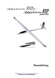
extra 300 hp - Graupner
extra 300 hp - Graupner
extra 300 hp - Graupner

Sie wollen auch ein ePaper? Erhöhen Sie die Reichweite Ihrer Titel.
YUMPU macht aus Druck-PDFs automatisch weboptimierte ePaper, die Google liebt.
Four hardwood blocks have to be glued to the nose bulkhead in order to support the<br />
cowl retaining screws.<br />
The cowl mounting points have to be marked on the fuselage before the cowl can be<br />
installed. Apply pieces of paper masking tape to the fuselage and mark these points<br />
to the rear of the cowl. If you now slide the cowl into position on the fuselage, the<br />
mounting points can be transferred to the moulding.<br />
When fitting the cowl ensure that the nose fairing lines up correctly with the spinner<br />
backplate. There should be about 1.5 mm clearance all round between the spinner<br />
backplate and the nose fairing when the cowl is in its final position.<br />
You may need to cut various openings in the cowl to clear the cylinder head /<br />
glowplug, silencer, needle valve, wing etc.; the positions will vary according to the<br />
engine you have installed. Drill holes initially, then file the openings out to final size.<br />
The ON / OFF switch can be installed in the right or left side of the fuselage. Cut<br />
away the covering film to suit the switch you wish to use, and install the unit using the<br />
retaining screws supplied with it.<br />
Assembling the EXTRA <strong>300</strong> HP<br />
To make it easier to connect the aileron servos to the receiver, we recommend that<br />
you connect a 180 mm extension lead to each of the appropriate receiver sockets (2<br />
and 5).<br />
Fit the wing joiner tube through the fuselage, and slide both wing panels onto the<br />
tube. Fit the four plastic screws to hold the wings against the fuselage sides, but take<br />
care not to over-tighten them; tighten them just to the point where the wings are firmly<br />
seated. The screws are supplied overlength; they can be shortened by about 20 mm<br />
if you wish.<br />
Balancing the EXTRA <strong>300</strong> HP<br />
Support the assembled model (fueltank empty) under both wing roots at a point<br />
about 100 to 110 mm aft of the wing root leading edge. If the CG position is correct,<br />
the model will hang level, with the nose inclined slightly down. If necessary, glue lead<br />
ballast to the nose or tail to obtain the correct balance, or re-position the receiver<br />
battery. All the control surfaces must be exactly at centre when the transmitter sticks<br />
and trims are in the neutral position; check this before the first flight.<br />
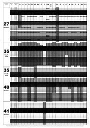
Control surface travels for normal flying<br />
Ailerons 30 mm up, 30 mm down<br />
Elevators 40 mm up, 40 mm down<br />
Rudder 95 mm right, 95 mm left<br />
GRAUPNER GmbH & Co. KG D-73230 KIRCHHEIM/TECK GERMANY<br />
Änderungen vorbehalten! Keine Haftung für Druckfehler 12/2007<br />
50