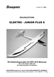
extra 300 hp - Graupner
extra 300 hp - Graupner
extra 300 hp - Graupner

Erfolgreiche ePaper selbst erstellen
Machen Sie aus Ihren PDF Publikationen ein blätterbares Flipbook mit unserer einzigartigen Google optimierten e-Paper Software.
Connect the appropriate extension leads to the aileron servo cables. Secure each<br />
connection with a drop of cyano or a piece of heat-shrink sleeve.<br />
Cut down the servo output levers as shown in the photo. Centre the servos from the<br />
transmitter, then press the output arms onto the servo output shafts.<br />
Drill 1.5 mm Ø pilot-holes in the wings for the servo retaining screws, using the<br />
servos themselves as templates. Allow the aileron servo leads to fall through the<br />
openings in the ribs until they exit the root ribs.<br />
Mark a centreline on the control surface hinges using a pencil.<br />
The hinges can now be slid into the control surfaces as far as the pencil marks, and<br />
glued in place with a few drops of thin cyano. The best method is to push the hinges<br />
into the slots in the control surfaces to a depth of about 1 mm, apply two drops of<br />
cyano to both<br />
sides of each hinge, then push them in as far as the pencil line.<br />
Allow the glue to set hard, then push the aileron hinges into the wing to a depth of<br />
about 1 mm.<br />
Apply cyano to both sides of the hinges as before, then push the ailerons against the<br />
wings, leaving a gap about 0.5 mm wide along the hinge axis. Repeat the procedure<br />
with the tailplane / elevators and fin / rudder.<br />
Allow the glue to set hard, then attach the horns to the control surfaces. You will<br />
need to drill 6 mm Ø holes in them at the marked points to accept the horn sockets.<br />
Remove the covering film over the area of the aluminium horn sockets. Fill the holes<br />
with glue and press the aluminium sockets into place; wipe off excess glue where it is<br />
squeezed out of the holes.<br />
The rudder horn consists of two M3 screws which have to be angled forward as<br />
shown in the photo.<br />
Screw the horn lugs onto the M3 screws of the elevator and aileron horns, and<br />
position the linkage holes at a point about 19 mm from the top surface of the control<br />
surface.<br />
Snip off excess screw length using side-cutters, and file the ends back flush with the<br />
horn lugs.<br />
The control surface pushrods can now be made up.<br />
Measure the distance from the linkage hole in the servo output arm to the linkage<br />
point of the horn lug, and cut suitable lengths from the M3 studding (threaded rod)<br />
supplied. Fit locknuts on the pushrods followed by clevises. Connect the clevises to<br />
GRAUPNER GmbH & Co. KG D-73230 KIRCHHEIM/TECK GERMANY<br />
Änderungen vorbehalten! Keine Haftung für Druckfehler 12/2007<br />
47