Montage- und Bedienungsanleitung Funk-Wandthermostat ... - ELV
Montage- und Bedienungsanleitung Funk-Wandthermostat ... - ELV
Montage- und Bedienungsanleitung Funk-Wandthermostat ... - ELV

Erfolgreiche ePaper selbst erstellen
Machen Sie aus Ihren PDF Publikationen ein blätterbares Flipbook mit unserer einzigartigen Google optimierten e-Paper Software.
D<br />
GB<br />
<strong>Montage</strong>- <strong>und</strong><br />
<strong>Bedienungsanleitung</strong><br />
<strong>Funk</strong>-<strong>Wandthermostat</strong><br />
HM-CC-TC Seite 4 - 30<br />
Installation and<br />
Operating Manual<br />
Radio-controlled<br />
room thermostat<br />
HM-CC-TC Page 32 - 58
1. Ausgabe Deutsch 12/2010<br />
Dokumentation © 2007 eQ-3 Ltd., Hong Kong<br />
Alle Rechte vorbehalten. Ohne schriftliche Zustimmung des<br />
Herausgebers darf dieses Handbuch auch nicht auszugsweise<br />
in irgendeiner Form reproduziert werden oder unter Verwendung<br />
elektronischer, mechanischer oder chemischer Verfahren vervielfältigt<br />
oder verarbeitet werden.<br />
Es ist möglich, dass das vorliegende Handbuch noch drucktechnische<br />
Mängel oder Druckfehler aufweist. Die Angaben in diesem<br />
Handbuch werden jedoch regelmäßig überprüft <strong>und</strong> Korrekturen<br />
in der nächsten Ausgabe vorgenommen. Für Fehler technischer<br />
oder drucktechnischer Art <strong>und</strong> ihre Folgen übernehmen wir keine<br />
Haftung.<br />
Alle Warenzeichen <strong>und</strong> Schutzrechte werden anerkannt.<br />
Printed in Hong Kong<br />
Änderungen im Sinne des technischen Fortschritts können ohne<br />
Vorankündigung vorgenommen werden.<br />
76190 / V 1.03<br />
2
1. English edition 12/2010<br />
Documentation © 2007 eQ-3 Ltd., Hong Kong<br />
All rights reserved. No parts of this manual may be reproduced or<br />
processed in any form using electronic, mechanical or chemical<br />
processes in part or in full without the prior explicit written permission<br />
of the publisher.<br />
It is quite possible that this manual has printing errors or defects.<br />
The details provided in this manual are checked regularly and<br />
corrections are done in the next edition. We do not assume any<br />
liability for technical or printing errors.<br />
All registered trade marks and copyrights are acknowledged.<br />
Printed in Hong Kong<br />
We reserve the right to make changes due to technical advancements<br />
without prior notice.<br />
76190 / V 1.03<br />
3
Inhaltsverzeichnis<br />
1 Hinweise zu dieser Anleitung ........................6<br />
2 Gefahrenhinweise .................................6<br />
3 <strong>Funk</strong>tion. ........................................6<br />
4 Allgemeine Systeminformation zu HomeMatic ..........8<br />
5 Allgemeine Hinweise zum <strong>Funk</strong>betrieb ................8<br />
6 Inbetriebnahme ...................................9<br />
6.1 Batterien einlegen <strong>und</strong> wechseln .....................9<br />
6.1.1 Batterien einlegen .................................9<br />
6.1.2 Verhalten nach Einlegen der Batterie. ................10<br />
6.1.3 Batterien wechseln ...............................11<br />
6.2 <strong>Montage</strong>. .......................................12<br />
6.2.1 Lieferumfang ....................................12<br />
6.2.2 <strong>Montage</strong> des Wandhalters .........................12<br />
7 Bedienung ......................................13<br />
7.1 Übersicht .......................................13<br />
7.2 Betriebsarten. ...................................14<br />
7.2.1 Automatik-Betrieb. ...............................14<br />
7.2.2 Handbetrieb. ....................................14<br />
7.2.3 Urlaubs-/Partyfunktion ............................14<br />
7.2.4 Zentralengeführter Betrieb .........................15<br />
7.3 Einstellungen im Auslieferungszustand ...............16<br />
7.4 Einstellen von Komfort- <strong>und</strong> Absenktemperatur ........16<br />
7.5 Heizpause ......................................17<br />
7.6 Frostschutzbetrieb ...............................18<br />
4
7.7 Tastensperre ....................................18<br />
7.8 Absenkbetrieb bei geöffneten Fenstern. ..............18<br />
8 Konfiguration <strong>und</strong> Sonderfunktionen .................20<br />
8.1 Einstellungen für den Automatikbetrieb „PRG“. ........21<br />
8.2 Einstellen von Datum <strong>und</strong> Uhrzeit „DAT“ ..............23<br />
8.3 Statusabfrage Stellantrieb „VST“ ....................23<br />
8.4 Statusabfrage Tür-/Fenstersensoren „WST“ ...........23<br />
8.5 Anlernen <strong>und</strong> Ablernen von Geräten „KON“ ...........24<br />
8.6 Einstellungen zur automatischen Entkalkungsfahrt „DEC“ 25<br />
8.7 Einstellen der verwendeten Temperatureinheit „C/F“ ....25<br />
8.8 Einstellung der Anzeige Soll-/Istwert „A/S“. ...........26<br />
8.9 Einstellung der Anzeige von Temperatur/Luftfeuchte „T/H“ 26<br />
8.10 Einstellung der Displayhinterleuchtung „ LIG“ .........26<br />
8.11 Einstellung der Offsetwerte für die einzelnen Stellantriebe<br />
„OFF“ ..........................................27<br />
8.12 Einstellen der Solltemperatur beim Lüften<br />
(Fenster-Auf-Temperatur) „WOT“ ....................27<br />
8.13 Einstellen der Position bei Störungen am Stellantrieb<br />
„EPO“. .........................................28<br />
8.14 Zurücksetzen in den Auslieferungszustand „RES“ . . . . . .28<br />
9 Fehlermeldungen ................................29<br />
10 Wartung <strong>und</strong> Reinigung ...........................29<br />
11 Technische Daten ................................30<br />
5
1 Hinweise zu dieser Anleitung<br />
Lesen Sie diese Anleitung sorgfältig, bevor Sie ihre HomeMatic<br />
Komponenten in Betrieb nehmen.<br />
Bewahren Sie die Anleitung zum späteren Nachschlagen auf!<br />
Wenn Sie das Gerät anderen Personen zur Nutzung überlassen,<br />
übergeben Sie auch diese <strong>Bedienungsanleitung</strong>.<br />
Benutzte Symbole:<br />
6<br />
Achtung! Hier wird auf eine Gefahr hingewiesen.<br />
Hinweis. Dieser Abschnitt enthält zusätzliche wichtige<br />
Informationen!<br />
2 Gefahrenhinweise<br />
Betreiben Sie das Gerät nur in Innenräumen <strong>und</strong> vermeiden Sie<br />
den Einfluss von Feuchtigkeit, Staub sowie Sonnen- oder andere<br />
Wärmebestrahlung.<br />
Öffnen Sie das Gerät nicht, es enthält keine durch den Anwender<br />
zu wartenden Teile.<br />
3 <strong>Funk</strong>tion<br />
Der <strong>Funk</strong>-<strong>Wandthermostat</strong> (HM-CC-TC) ist ein Einzelraumregler.<br />
Er misst die Raumtemperatur <strong>und</strong> vergleicht die gemessene<br />
Temperatur mit der durch das Zeitprogramm bzw. der von Hand<br />
vorgegebenen Soll-Temperatur. Aus der Differenz errechnet der<br />
Regelalgorithmus, wie der oder die <strong>Funk</strong>-Stellantriebe (HM-CC-VD)<br />
das Ventil fahren müssen, um die gewünschte Temperatur zu<br />
erreichen.
In einem zyklischen Zeitraster, mit einer Zykluszeit zwischen 120<br />
<strong>und</strong> 184 Sek<strong>und</strong>en, überträgt der <strong>Wandthermostat</strong> Befehle zu<br />
dem am Heizkörper montierten Stellantrieb. Der Stellantrieb bestätigt<br />
den übertragenen <strong>Funk</strong> Befehl <strong>und</strong> steuert die zugeführte<br />
Wärmeträgermenge entsprechend.<br />
Über die HomeMatic Zentrale ist es möglich Veränderungen der<br />
Temperaturvoreinstellung oder des Zeitprogramms im <strong>Wandthermostat</strong>en<br />
bequem über eine grafische Oberfläche vorzunehmen.<br />
Die Regelung wird weiterhin im entsprechenden Raum autark<br />
vom <strong>Wandthermostat</strong> durchgeführt.<br />
Durch Anlernen eines oder mehrerer Tür-Fensterkontakte bzw.<br />
Fenster-Drehgriffkontakte am <strong>Wandthermostat</strong>, kann die Fensterstellung<br />
(offen/geschlossen) ausgewertet werden <strong>und</strong> in den<br />
Regelalgorithmus einfließen.<br />
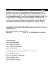
(A) Stellrad (zur Dateneingabe)<br />
(B) Geräte-LED<br />
(C) Display<br />
(D) Bedientasten (Menu, OK, Tag-/Nachtumschaltung)<br />
(E) Aufnahme Wandhalter<br />
(F) Batteriefach<br />
(G) Wandhalter<br />
7
4 Allgemeine Systeminformation zu<br />
HomeMatic<br />
Dieses Gerät ist Teil des HomeMatic Haussteuersystems <strong>und</strong><br />
arbeitet mit dem bidirektionalen BidCoS® <strong>Funk</strong>protokoll.<br />
Alle Geräte werden mit einer Standardkonfiguration ausgeliefert.<br />
Darüber hinaus ist die <strong>Funk</strong>tion des Gerätes über ein Programmiergerät<br />
<strong>und</strong> Software konfigurierbar. Welcher weitergehende<br />
<strong>Funk</strong>tionsumfang sich damit ergibt, <strong>und</strong> welche Zusatzfunktionen<br />
sich im HomeMatic System im Zusammenspiel mit weiteren<br />
Komponenten ergeben, entnehmen Sie bitte der gesonderten<br />
Konfigurationsanleitung oder dem HomeMatic Systemhandbuch.<br />
Alle technischen Dokumente <strong>und</strong> Updates finden Sie stets aktuell<br />
unter www.HomeMatic.com.<br />
5 Allgemeine Hinweise zum <strong>Funk</strong>betrieb<br />
Die <strong>Funk</strong>-Übertragung wird auf einem nicht exklusiven Übertragungsweg<br />
realisiert weshalb Störungen nicht ausgeschlossen<br />
werden können.<br />
Weitere Störeinflüsse können hervorgerufen werden durch<br />
Schaltvorgänge, Elektromotoren oder defekte Elektrogeräte.<br />
Die Reichweite in Gebäuden kann stark von der im<br />
Freifeld abweichen. Außer der Sendeleistung <strong>und</strong> den<br />
Empfangseigenschaften der Empfänger spielen Umwelteinflüsse<br />
wie Luftfeuchtigkeit neben baulichen Gegebenheiten<br />
vor Ort eine wichtige Rolle.<br />
Hiermit erklärt die eQ-3 Entwicklung GmbH, dass sich dieses<br />
Gerät in Übereinstimmung mit den gr<strong>und</strong>legenden Anforderungen<br />
<strong>und</strong> den anderen relevanten Vorschriften der Richtlinie<br />
1999/5/EG befindet.<br />
Die vollständige Konformitätserklärung finden Sie unter:<br />
www.HomeMatic.com.<br />
8
Zur Wandmontage des <strong>Wandthermostat</strong>en zeichnen Sie die<br />
Bohrlöcher anhand des Wandhalters an. Dabei muss der Wandhalter<br />
mit der halbkreisförmigen Seite nach oben <strong>und</strong> mit der<br />
Seite mit der kleinen halbkugelförmigen Vertiefung im oberen Teil<br />
nach vorne orientiert sein. Zum Anzeichnen markieren Sie eine<br />
Position in der Mitte der Langlöcher für die Schrauben.<br />
Bohren Sie mit einem 6 mm Bohrer Befestigungslöcher, <strong>und</strong><br />
benutzen Sie die mitgelieferten Dübel <strong>und</strong> Schrauben zur Befestigung.<br />
Bevor Sie die Schrauben des Wandhalters endgültig<br />
festdrehen, können Sie den Halter mit Hilfe einer Wasserwaage<br />
endgültig ausrichten <strong>und</strong> dann die Schrauben fest ziehen.<br />
6 Inbetriebnahme<br />
6.1 Batterien einlegen <strong>und</strong> wechseln<br />
6.1.1 Batterien einlegen<br />
Zum Einlegen oder Wechseln der Batterie legen Sie den <strong>Wandthermostat</strong><br />
mit dem Display nach unten auf eine weiche Unterlage<br />
(damit die Blende <strong>und</strong> die Displayabdeckung nicht verkratzen).<br />
Schieben Sie den Batteriefachdeckel in Pfeilrichtung <strong>und</strong><br />
nehmen ihn ab. Legen Sie zwei Mignon Batterien polungsrichtig<br />
ins Batteriefach (siehe Zeichnung).<br />
9
6.1.2 Verhalten nach Einlegen der Batterie<br />
Nach dem Einlegen der Batterien erfolgt ein kurzer Test der<br />
LC-Anzeige mit anschließender Anzeige der Versionsnummer.<br />
Sie müssen nun nacheinander Datum <strong>und</strong> Uhrzeit eingeben.<br />
Dazu verwenden Sie das Stellrad. Bestätigen Sie danach ihre<br />
Eingabe mit der „OK“-Taste <strong>und</strong> Sie gelangen zum nächsten<br />
Eingabeschritt. Während der Datums- <strong>und</strong> Zeiteingabe können<br />
Sie mit der „Menu“-Taste jederzeit wieder zum vorhergehenden<br />
Schritt wechseln.<br />
• Kalenderjahr<br />
• Kalendermonat<br />
• Wochentag<br />
10
• Zeiteinstellung - St<strong>und</strong>en<br />
• Zeiteinstellung - Minuten<br />
Damit sind Datum <strong>und</strong> Uhrzeit im Heizungsregler eingestellt <strong>und</strong><br />
es wird zur Standardanzeige gewechselt.<br />
Wird der Heizungsregler an eine Zentrale angelernt, wird der<br />
Regler beim nächsten Batteriewechsel Datum <strong>und</strong> Uhrzeit von<br />
der Zentrale anfordern, gelingt dies, wird sofort zu Standardanzeige<br />
gewechselt.<br />
6.1.3 Batterien wechseln<br />
Vorsicht! Explosionsgefahr bei unsachgemäßem Austausch der<br />
Batterie.<br />
Verbrauchte Batterien gehören nicht in den<br />
Hausmüll! Entsorgen Sie diese in Ihrer örtlichen<br />
Batteriesammelstelle!<br />
Werden fast leere Batterien für den <strong>Wandthermostat</strong>en gemeldet<br />
(siehe Abschnitt 9 Fehlermeldungen) müssen Sie die alten Batterien<br />
durch zwei neue des Typs LR6 (Mignon) ersetzen. Öffnen Sie wie<br />
oben beschrieben das Batteriefach, entnehmen Sie die alten Batterien<br />
<strong>und</strong> legen Sie neue ein. Achten Sie dabei auf die richtige Polung.<br />
11
6.2 <strong>Montage</strong><br />
6.2.1 Lieferumfang<br />
• <strong>Wandthermostat</strong><br />
• Wandhalter<br />
• 2 Stück Holzschrauben 3,5 x 30<br />
• 2 Stück Dübel 6 mm<br />
• 2 Stück Batterien LR6 (Mignon)<br />
6.2.2 <strong>Montage</strong> des Wandhalters<br />
Zur Wandmontage des <strong>Wandthermostat</strong>en zeichnen Sie die<br />
Bohrlöcher anhand des Wandhalters an. Dabei muss der Wandhalter<br />
mit der halbkreisförmigen Seite nach oben <strong>und</strong> mit der<br />
Seite mit der kleinen halbkugelförmigen Vertiefung im oberen Teil<br />
nach vorne orientiert sein. Zum Anzeichnen markieren Sie eine<br />
Position in der Mitte der Langlöcher für die Schrauben.<br />
Bohren Sie mit einem 6 mm Bohrer Befestigungslöcher, <strong>und</strong><br />
benutzen Sie die mitgelieferten Dübel <strong>und</strong> Schrauben zur Befestigung.<br />
Bevor Sie die Schrauben des Wandhalters endgültig<br />
festdrehen, können Sie den Halter mit Hilfe einer Wasserwaage<br />
endgültig ausrichten <strong>und</strong> dann die Schrauben fest ziehen.<br />
12
7 Bedienung<br />
7.1 Übersicht<br />
Der Heizungsregler besitzt im Stand-Alone-Betrieb (Betrieb ohne<br />
HomeMatic Zentrale) drei Betriebsarten, den Automatikbetrieb,<br />
den manuellen Betrieb <strong>und</strong> den Urlaub/Party-Betrieb. Ist der<br />
Heizungsregler mit einer HomeMatic Zentrale verknüpft kommt<br />
zusätzlich der Zentralen-Betrieb dazu.<br />
Mit der Menütaste können Sie zwischen den einzelnen Betriebsarten<br />
wechseln.<br />
Durch wiederholtes Drücken sind dabei die verschiedenen Modi<br />
nacheinander abrufbar.<br />
Die Displayhintergr<strong>und</strong>beleuchtung (falls aktiviert) schaltete<br />
immer dann ein, wenn ein Taster oder das Stellrad betätigt wird,<br />
die Zeit für das Nachleuchten können Sie einstellen.<br />
Standardmäßig wird im Display die aktuelle Uhrzeit, das Datum<br />
<strong>und</strong> die Ist-Temperatur im Wechsel mit der Luftfeuchte angezeigt.<br />
Sie können aber auch einen Anzeigemodus wählen<br />
bei dem die Soll-Temperatur <strong>und</strong> die Luftfeuchte im Wechsel<br />
angezeigt werden. Mit der OK-Taste können Sie die jeweils<br />
ausgeblendete Temperatur kurz anzeigen (Soll-Temperatur bzw.<br />
Ist-Temperatur).<br />
Sobald eine HomeMatic-Komponente angelernt ist, erscheint<br />
das Antennensymbol für bestehenden <strong>Funk</strong>empfang.<br />
Am Display des <strong>Wandthermostat</strong>en werden sämtliche Warnungen<br />
„LowBat“ (fast leere Batterie) der angelernten Komponenten <strong>und</strong><br />
des Thermostaten selbst angezeigt. Symbolisiert wird eine solche<br />
Meldung durch das Batteriesymbol ergänzt um ein<br />
• S für einen Sensor (Tür-Fensterkontakt, Fenster-Drehgriffkontakt)<br />
• V für einen Stellantrieb<br />
13
Über das Menü „Sonderfunktionen“ „VST“ bzw. „WST“ kann<br />
dann das betroffene Gerät leicht gef<strong>und</strong>en werden.<br />
Erscheint nur das Batteriesymbol gilt die Meldung für den <strong>Wandthermostat</strong>en<br />
selbst.<br />
7.2 Betriebsarten<br />
7.2.1 Automatik-Betrieb<br />
Im Automatikbetrieb (Anzeige „Auto“) folgt die Raumtemperatur<br />
dem eingestellten Wochentagsprogramm. Der Temperaturverlauf<br />
für den aktuellen Wochentag ist auf der Balkenskala am unteren<br />
Displayrand dargestellt. Dabei wird der Balken immer dann dargestellt,<br />
wenn die Temperatur größer oder gleich der Komforttemperatur<br />
ist.<br />
Soll die Temperatur vorübergehend verändert werden, so kann<br />
dies einfach über das Stellrad erfolgen. Beim nächsten regulären<br />
Temperaturwechsel im Zeitprogramm kehrt der Thermostat<br />
selbsttätig zum zeitgesteuerten Programm zurück<br />
7.2.2 Handbetrieb<br />
Die <strong>Funk</strong>tion des Reglers im Handbetrieb (Anzeige „Manu“) entspricht<br />
der eines konventionellen Thermostaten.<br />
Im Handbetrieb bleibt der Regler dauerhaft auf der eingestellten<br />
Temperatur. Ein automatischer zeitgesteuerter Wechsel erfolgt<br />
nicht. Ebenso wenig wird auf Sensoren die ein offenes Fenster<br />
anzeigen reagiert.<br />
7.2.3 Urlaubs-/Partyfunktion<br />
In dieser Betriebsart (Koffer-Symbol im Display) bleibt die Temperatur<br />
für einen definierten Zeitraum (z. B. für die Dauer einer<br />
Party oder eines Urlaubs) auf einem festen Temperaturwert.<br />
Danach wechselt der Regler selbsttätig in den Automatikbetrieb<br />
bzw. in den Zentralen-Betrieb. Zum Zentralen-Betrieb wird immer<br />
dann gewechselt, wenn der Regler vor dem Urlaub/Party-Betrieb<br />
im Zentralen-Betrieb war <strong>und</strong> der Urlaub/Party-Betrieb von der<br />
Zentrale aktiviert wurde.<br />
14
Ist ein Tür-Fenster-Kontakt oder ein Fenster-Drehgriffkontakt im<br />
System integriert, wird auch während des Urlaub/Party-Betriebs<br />
die Tür- bzw. Fensterposition berücksichtigt, d.h. im Fall einer offenen<br />
überwachten Tür bzw. eines offenen überwachten Fensters<br />
wird für die Regelung die Fenster-Auf-Temperatur gewählt.<br />
Einstellung des Urlaub/Party-Betriebs:<br />
Wechseln Sie mit der „Menu“-Taste in den Urlaub/Party-Betrieb.<br />
Stellen Sie anschließend den Zeitraum ein, für den diese <strong>Funk</strong>tion<br />
ausgeführt werden soll. Für die folgenden 24 St<strong>und</strong>en ist<br />
eine Abstufung im ½-St<strong>und</strong>en-Raster möglich. Darüber hinaus<br />
erfolgt die Abstufung im Tages-Raster. Der ausgewählte Tag gibt<br />
den Zeitpunkt wieder, an dem der Regler zum Tagesbeginn um<br />
0:00 Uhr in den Automatikbetrieb zurück wechselt.<br />
Nach Einstellung des gewünschten Zeitraumes, bestätigen Sie<br />
Ihre Eingabe mit der „OK“-Taste.<br />
Abschließend stellen Sie die gewünschte Temperatur für die Zeitdauer<br />
des Urlaub/Party-Betriebs mit dem Stellrad ein, alternativ<br />
können Sie mit der „Tag/Nacht“-Taste die Komfort- oder Absenktemperatur<br />
als Temperatur für den Urlaubs/Party-Betrieb wählen.<br />
Sie können den Urlaubs/Party-Betrieb jederzeit mit der „Menu“-<br />
Taste verlassen.<br />
7.2.4 Zentralengeführter Betrieb<br />
In dieser Betriebsart (Anzeige „Cent“) wird der Temperatur-Sollwert<br />
von der Zentrale vorgegeben <strong>und</strong> das Verhalten ist mit dem<br />
im Handbetrieb identisch.<br />
15
7.3 Einstellungen im Auslieferungszustand<br />
Im Auslieferungszustand sind bereits alle erforderlichen Einstellungen<br />
des Systems mit Standardwerten vorbelegt:<br />
• Komforttemperatur: 21 °C<br />
• Absenktemperatur: 17 °C<br />
• Temperaturphase 1: 17 °C von 0:00 Uhr bis 6:00 Uhr<br />
• Temperaturphase 2: 21 °C von 6:00 Uhr bis 12:00 Uhr<br />
• Temperaturphase 3: 21 °C von 12:00 Uhr bis 23:00 Uhr<br />
• Temperaturphase 4: 17 °C von 23:00 Uhr bis 0:00 Uhr<br />
• Fenster-Auf-Temperatur: 12 °C (für alle angelernten Sensoren)<br />
• Entkalkungsfahrt: Samstag, 11:00 Uhr<br />
• Anzeige der Temperatur <strong>und</strong> der Luftfeuchte im Wechsel<br />
• Displayhintergr<strong>und</strong>beleuchtung aus<br />
Alle genannten Einstellungen können Sie verändern <strong>und</strong> so an<br />
Ihre individuellen Bedürfnisse anpassen. Ein Rücksetzen auf<br />
die Werkseinstellung ist jederzeit über das Menü „Sonderfunktionen“:<br />
„RES“ möglich.<br />
7.4 Einstellen von Komfort- <strong>und</strong> Absenktemperatur<br />
Mit der Taste „Tag/Nacht“ (Sonne- oder Mondsymbol im Display)<br />
können Sie schnell zwischen Komfort- <strong>und</strong> Absenkbetrieb umschalten.<br />
Dies ist insbesondere dann Hilfreich, wenn die Nutzung<br />
eines Raumes vom eingestellten Zeitprogramm abweicht.<br />
Um die Komfort- <strong>und</strong> Absenktemperatur einzustellen drücken<br />
Sie die „Tag/Nacht“-Taste für länger als 3 Sek<strong>und</strong>en. Daraufhin<br />
erscheint in der Anzeige:<br />
16
Wählen Sie mit dem Stellrad die gewünschte Komforttemperatur<br />
<strong>und</strong> bestätigen Sie Ihre Eingabe mit der „OK“-Taste.<br />
Die Anzeige wechselt nun zur Eingabe der Absenktemperatur.<br />
Wählen Sie mit dem Stellrad die gewünschte Absenktemperatur<br />
<strong>und</strong> bestätigen Sie Ihre Eingabe mit der „OK“-Taste.<br />
Nach Einstellung der Komfort- <strong>und</strong> Absenktemperatur wechselt<br />
die Anzeige zurück zur Standardanzeige.<br />
7.5 Heizpause<br />
Ist die Heizung im Sommer abgeschaltet, können die Batterien<br />
des Stellantriebes geschont werden:<br />
• Das Ventil wird geöffnet <strong>und</strong> verbleibt in dieser Stellung<br />
• Der wöchentliche Verkalkungsschutz wird weiterhin durchgeführt<br />
Um die Heizpause zu aktiviere, wechseln Sie in den Handbetrieb<br />
<strong>und</strong> drehen das Stellrad solange rechtsrum, bis „ON“ in der<br />
Anzeige erscheint.<br />
Zum Beenden der Heizpause verlassen Sie den Handbetrieb<br />
mit der „Menu“-Taste oder drehen Sie das Stellrad<br />
linksrum.<br />
17
7.6 Frostschutzbetrieb<br />
Wählen Sie diese Betriebsart, wenn der Raum gar nicht geheizt<br />
werden soll.<br />
• Das Ventil wird geschlossen <strong>und</strong> verbleibt in dieser Stellung.<br />
• Nur bei Frostgefahr (Temperatur unter 5 °C) wird das Ventil<br />
geöffnet.<br />
• Der wöchentliche Verkalkungsschutz wird weiterhin durchgeführt.<br />
Um das Ventil zu schließen, wechseln Sie mit der „Menu“-Taste<br />
in den manuellen Betrieb („Manu“)<strong>und</strong> drehen das Stellrad solange<br />
nach links, bis „OFF“ in der Anzeige erscheint.<br />
7.7 Tastensperre<br />
Um das Gerät vor einem unbeabsichtigten Verstellen zu schützen,<br />
ist eine Sperrfunktion für die Tasten <strong>und</strong> das Stellrad<br />
integriert.<br />
Sie können die Sperre aktivieren, indem Sie die Tasten „Menu“<br />
<strong>und</strong> „OK“ gleichzeitig betätigen. In der Anzeige erscheint „LOC“,<br />
alle Bedienfunktionen sind nun gesperrt.<br />
Um die Sperrfunktion aufzuheben, drücken Sie die Tasten<br />
„Menu“ <strong>und</strong> „OK“ solange gleichzeitig bis „LOC“ aus der Anzeige<br />
verschwindet.<br />
7.8 Absenkbetrieb bei geöffneten Fenstern<br />
Sind Tür-Fenster-Kontakte bzw. Fenster-Drehgriffkontakte installiert,<br />
melden diese den Tür- bzw. Fensterstatus. Wird der Status<br />
„Tür offen“ bzw. „Fenster offen“ an den Heizungsregler gemeldet,<br />
so wird als Soll-Temperatur die für jeden Sensor individuell einstellbare<br />
Fenster-Auf-Temperatur angefahren. Dabei ist immer die<br />
Fenster-Auf-Temperatur des zuletzt ausgelösten Sensors gültig!<br />
18
Beispiel:<br />
Sensor Fenster-Auf-Temperatur<br />
HM-Sec-SC (1) Fenster 1 14°C<br />
HM-Sec-SC (2) Fenster 2 12°C<br />
HM-Sec-RHS Fenster 3 16°C<br />
Wird zunächst das Fenster 1 geöffnet regelt der Wanthermostat<br />
auf 14°C. Wird Fenster 2 geöffnet wird auf 12°C geregelt. Nach<br />
Öffnen von Fenster 3 ist 16°C die Zieltemperatur. Schließt man<br />
nun Fenster 1 oder 2 wird weiterhin auf 16°C geregelt. Schließt<br />
man hingegen Fenster 3 (1 <strong>und</strong> 2 bleiben offen) wird 12°C angefahren.<br />
14°C wird erst dann wieder angefahren, wenn Fenster 2<br />
<strong>und</strong> 3 geschlossen sind.<br />
Sind alle Fenster wieder als geschlossen gemeldet fährt<br />
der Raumregler wieder die ursprünglichen Temperatur an.<br />
Auch bei geöffnetem Fenster kann die Temperatur jederzeit<br />
von Hand auf einen anderen Wert verändert werden.<br />
Sobald ein Tür-Fenster-Kontakt bzw. ein Fenster-Drehgriffkontakt<br />
an den <strong>Wandthermostat</strong> angelernt wurde, aktiviert<br />
dieser seinen WAKE-ON-RADIO-MODE, damit die<br />
Ereignismitteilungen die vom Tür-Fenster-Kontakt bzw. Tür-Fenster-Drehgriff<br />
gesendet werden, empfangen werden können. Dies<br />
hat zu Folge dass der Stromverbrauchs des Gerätes ansteigt <strong>und</strong><br />
dadurch die Batterielebensdauer gesenkt wird.<br />
19
8 Konfiguration <strong>und</strong> Sonderfunktionen<br />
Im Menü „Sonderfunktion“ können Sie individuelle Einstellungen<br />
vornehmen. Um in das Menü der „Sonderfunktionen“ zu gelangen,<br />
drücken Sie die Taste „Menu“ für 3 Sek<strong>und</strong>en.<br />
Einzelne Menüpunkte wählen Sie mit Hilfe des Stellrads aus. Mit<br />
der „OK“-Taste wechseln Sie in das gewünschte Untermenü. Ist<br />
ein Menüpunkt vollständig durchlaufen, werden die Änderungen<br />
gespeichert. Im Display erscheint ein „OK“ im Display signalisiert.<br />
Mit dem Taster „Menu“ können Sie von jedem Untermenü zurück<br />
zum jeweiligen höhern Menüpunkt wechseln. Auch ein Abbrechen<br />
der Eingabe <strong>und</strong> das Verlassen der „Sonderfunktionen“ ist<br />
so möglich.<br />
Das Menü „Sonderfunktionen“ wird automatisch beendet wenn<br />
90 Sek<strong>und</strong>en keine Einstellung bzw. kein Tastendruck erfolgt.<br />
Sonderfunktionen sind:<br />
PRG Temperaturgestaltung für den Automatikbetrieb<br />
DAT Einstellung von Datum <strong>und</strong> Uhrzeit<br />
VST Anzeige von Ventilposition, Batteriestatus <strong>und</strong> Empfangsstatus<br />
WST Anzeige von Fensterposition, Batteriestatus <strong>und</strong> Empfangsstatus<br />
KON HomeMatic-Gerätekonfiguration<br />
DEC Festlegung des Zeitpunktes der Entkalkungsfahrt<br />
C/F Festlegung der Einheit der Temperatur (Celsius oder<br />
Fahrenheit)<br />
A/S Festlegung ob Ist- oder die Sollwert angezeigt werden<br />
soll<br />
T/H Anzeige der Temperatur <strong>und</strong> der Luftfeuchte im Wechsel<br />
LIG Dauer der Displayhintergr<strong>und</strong>beleuchtung<br />
OFF Ventil Offseteinstellung<br />
EPO Position die der Ventilantrieb automatisch bei einem<br />
Fehler anfährt<br />
WOT Fenster-Auf-Temperatur<br />
RES Rücksetzen auf Werkseinstellung<br />
20
8.1 Einstellungen für den Automatikbetrieb „PRG“<br />
Die Zeitpunkte für den automatischen Wechsel zwischen den<br />
verschiedenen Temperaturphasen können für jeden Wochentag<br />
getrennt verändert werden <strong>und</strong> damit den persönlichen Lebensgewohnheiten<br />
angepasst werden.<br />
Bei der Einstellung der einzelnen Phasen ist am linken Rand in<br />
der oberen Zeile immer der Startzeitpunkt für die jeweilige Temperaturphase<br />
abgebildet, dieser ergibt sich automatisch durch<br />
den Endzeitpunkt der vorhergehenden Temperaturphase.<br />
Für jeden Tag können Sie bis zu 24 Zeitphasen definieren.<br />
Rufen Sie die Sonderfunktion „PRG“ auf.<br />
Drücken Sie die „OK“-Taste um die Einstellungen am Zeitprogramm<br />
vorzunehmen.<br />
Art des Zeitprogramms:<br />
Wählen Sie mit dem Stellrad den Tag bzw. die Tage, für den<br />
das Zeitprogramm verändert werden soll. Folgende Auswahl ist<br />
möglich:<br />
• einzelne Tage (Mo-So)<br />
• alle Werktage (Mo-Fr)<br />
• Wochenende (Sa-So)<br />
Bestätigen Sie Ihre Eingabe mit OK.<br />
Zeitphase<br />
Es erscheint die Anzeige für die erste Temperaturphasen-Zeit.<br />
In der oberen Zeile steht dabei der nicht veränderbare Startzeitpunkt<br />
in der unteren Zeile der variable Endzeitpunkt für das Ende<br />
der ersten Temperaturphase:<br />
21
Stellen Sie mit dem Stellrad den Endzeitpunkt für die erste Temperaturphase<br />
ein <strong>und</strong> bestätigen Sie mit der „OK“-Taste.<br />
Es erscheint in der Anzeige die Soll-Temperatur für den ausgewählten<br />
Zeitbereich.<br />
Stellen Sie mit dem Stellrad die gewünschte Temperatur ein.<br />
Alternativ können Sie mit der „Mond/Sonne“-Taste die Komforttemperatur<br />
oder die Absenktemperatur als Temperatur auswählen.<br />
Ihre Einstellung bestätigen Sie mit der „OK“-Taste.<br />
Es erscheint die Anzeige für die nächste Temperaturphasen-Zeit.<br />
In der oberen Zeile steht dabei wieder der nicht veränderbare<br />
Startzeitpunkt in der unteren Zeile der variable Endzeitpunkt für<br />
das Ende dieser Temperaturphase. Weitere Temperaturphasen<br />
können Sie nun wie bisher beschrieben eingeben.<br />
Die Skala am unteren Displayrand folgt den aktuellen Änderungen,<br />
so dass die Auswirkungen auf das Tagesprofil direkt zu<br />
erkennen sind (die Skala ist immer dann vorhanden, wenn der<br />
Temperaturwert größer oder gleich der Komforttemperatur ist).<br />
22
Schließen Sie ein Zeitprogramm ab indem Sie als Endzeit 0:00<br />
Uhr einzustellen. 0:00 Uhr als Endzeit wird automatisch eingestellt,<br />
wenn 24 Temperaturphasen erstellt wurden.<br />
Der Programmabschluss wird durch ein „OK“ in der Anzeige<br />
signalisiert.<br />
8.2 Einstellen von Datum <strong>und</strong> Uhrzeit „DAT“<br />
Rufen Sie die Sonderfunktion „DAT“ auf. Drücken Sie die „OK“-<br />
Taste um die Uhrzeit <strong>und</strong> Datum einzustellen. Gehen Sie dabei<br />
vor wie im Abschnitt „Inbetriebnahme“ beschrieben.<br />
8.3 Statusabfrage Stellantriebe „VST“<br />
Unter diesem Menüpunkt können Sie sich den Öffnungszustand<br />
der Stellantriebe, deren Batteriestatus <strong>und</strong> den Status der <strong>Funk</strong>verbindung<br />
anzeigen lassen.<br />
Rufen Sie die Sonderfunktion „VST“ auf.<br />
Drücken Sie die „OK“-Taste um die Informationen zu den Stellantrieben<br />
abzufragen.<br />
In der Anzeige wird die Ventilöffnung in Prozent angegeben. Sind<br />
die Batterie nahezu entladen wird zusätzlich das Batteriesymbol<br />
eingeblendet. Ist die <strong>Funk</strong>verbindung zwischen Ventilantrieb <strong>und</strong><br />
Regler gestört, blinkt außerdem das Antennensymbole. Mit dem<br />
Stellrad kann zwischen den angelernten Stellantrieben gewechselt<br />
werden.<br />
8.4 Statusabfrage Tür-/Fenstersensoren „WST“<br />
Unter diesem Menüpunkt können Sie im Display den aktuelle<br />
Status der Tür-Fenster-Kontakte bzw. Tür-Fenster-Drehgriffe<br />
abfragen.<br />
23
Rufen Sie die Sonderfunktion „WST“ auf.<br />
Drücken Sie die „OK“-Taste um die Informationen zu den Sensoren<br />
zu erhalten.<br />
In der Anzeige wird das Fenstersymbol dargestellt <strong>und</strong> die Fensterposition<br />
(„OPE“ oder „CLO“) angegeben. Sind die Batterie<br />
nahezu entladen wird zusätzlich das Batteriesymbol eingeblendet.<br />
Ist die <strong>Funk</strong>verbindung zwischen Sensor <strong>und</strong> Regler gestört,<br />
blinkt außerdem das Antennensymbole. Mit dem Stellrad kann<br />
zwischen den angelernten Sensoren gewechselt werden.<br />
8.5 Anlernen <strong>und</strong> Ablernen von Geräten „KON“<br />
Nach Auswahl dieses Menüpunktes können Sie neue Geräte an<br />
den Heizungsregler anlernen werden oder bereits angelernte<br />
Geräte ablernen.<br />
Rufen Sie die Sonderfunktion „KON“ auf.<br />
Drücken Sie die „OK“-Taste. Wählen Sie nun mit dem Stellrad<br />
aus, ob Sie an- oder ablernen möchten:<br />
Anlernen („ADD“)<br />
Das Gerät befindet sich nun für ca. 20 Sek<strong>und</strong>en im Anlernmodus.<br />
Wird währende dieser Zeit eine Komponente erfolgreich<br />
angelernt erscheint „OK“ im Display.<br />
Ablernen („DEL“)<br />
Ablernen ist nur möglich, wenn der <strong>Wandthermostat</strong> nicht<br />
an eine Zentrale angelernt ist.<br />
Wählen Sie mit dem Stellrad die Komponente, die abgelernt<br />
werden soll aus. Ventilantriebe werden im Display lediglich durch<br />
ihre Gerätenummer dargestellt, Tür-Fenster-Kontakt bzw. Tür-<br />
Fenster-Drehgriffe sind zusätzlich zu ihrer Gerätenummer durch<br />
das Fenstersymbol im Display gekennzeichnet. Bestätigen Sie<br />
das Ablernen mit der „OK“-Taste. Nach erfolgreichen Ablernen<br />
erscheint im Display erscheint für ca. 3 Sek<strong>und</strong>en „OK“.<br />
24
Sie können den Anlernmodus alternativ auch durch<br />
langen Tastendruck ( > 5 Sek<strong>und</strong>en) der „OK“-Taste<br />
aktivieren.<br />
8.6 Einstellungen zur automatischen Entkalkungsfahrt<br />
„DEC“<br />
Um zu verhindern, dass sich das Heizungsventil durch Ablagerungen<br />
festsetzt wird es einmal wöchentlich vollständig geöffnet<br />
<strong>und</strong> geschlossen. Sie können den Zeitpunkt, an dem diese<br />
Entkalkung durchgeführt wird, durch die Sonderfunktion „DEC“<br />
verändern.<br />
Rufen Sie dazu die Sonderfunktion „DEC“ auf <strong>und</strong> bestätigen mit<br />
der „OK“-Taste.<br />
Wählen Sie zunächst den Wochentag für die Entkalkungsfahrt<br />
auf <strong>und</strong> bestätigen Sie mit der „OK“-Taste. Wählen Sie dann mit<br />
dem Stellrad die Uhrzeit für die Entkalkungsfahrt. Bestätigen Sie<br />
Ihre Eingabe mit der „OK“-Taste.<br />
8.7 Einstellen der verwendeten Temperatureinheit<br />
„C/F“<br />
In diesem Menüpunkt können Sie zwischen einer Temperaturanzeige<br />
in Grad Celsius oder Grad Fahrenheit umschalten.<br />
Wählen Sie die Sonderfunktion „C/F“ <strong>und</strong> bestätigen Sie mit der<br />
„OK“-Taste. Wählen Sie die gewünschte Temperatureinheit mit<br />
dem Handrad aus.<br />
25
8.8 Einstellung der Anzeige Soll-/Istwert „A/S“<br />
Unter diesem Menüpunkt können Sie einstellen, ob im Display<br />
die Ist- oder die Soll-Temperatur angezeigt werden soll.<br />
Wählen Sie dazu die Sonderfunktion „A/S“ <strong>und</strong> bestätigen Sie<br />
mit der „OK“-Taste. Nun können Sie mit dem Stellrad zwischen<br />
„Actual“ (Isttemperatur) <strong>und</strong> „Set“ (Solltemperatur) auswählen.<br />
8.9 Einstellung der Anzeige von<br />
Temperatur/Luftfeuchte „T/H“<br />
Wählen Sie mit diesem Menüpunkt aus, ob im Display die Temperatur<br />
<strong>und</strong> die Luftfeuchtigkeit im Wechsel oder dauerhaft die<br />
Temperatur angezeigt wird.<br />
Dazu wählen Sie die Sonderfunktion „T/H“ aus <strong>und</strong> bestätigen<br />
mit der „OK“-Taste.<br />
Wählen Sie mit dem Stellrad „ON“ für Temperatur/Feuchte im<br />
Wechsel <strong>und</strong> „OFF“ zur dauerhaften Anzeige der Temperatur.<br />
8.10 Einstellung der Displayhinterleuchtung „ LIG“<br />
Stellen Sie unter diesem Menüpunkt die Leuchtdauer der Hintergr<strong>und</strong>beleuchtung<br />
nach Tastenbetätigung ein.<br />
Wählen Sie dazu die Sonderfunktion „LIG“ <strong>und</strong> bestätigen Sie<br />
mit der „OK“-Taste.<br />
Wählen Sie mit dem Stellrad die Zeit für die Dauer der Displayhintergr<strong>und</strong>beleuchtung<br />
nach tastendruck aus (OFF, 5s, 10s, 15s,<br />
20s, 25s).<br />
Schließen Sie Ihre Eingabe mit der „OK“-Taste ab.<br />
26<br />
Bei niedrigem Batteriestand wird die Displayhinterleuchtung<br />
nicht mehr aktiviert!
8.11 Einstellung der Offsetwerte für die einzelnen<br />
Stellantriebe „OFF“<br />
Werden mehrere Stellantrieb an unterschiedlichen Heizkörpern<br />
von einem Regler gesteuert, ist es möglich, dass die einzelnen<br />
Heizkörper ungleichmäßig stark heizen. Das kann an einem stark<br />
voneinander abweichenden Durchflussverhalten der Ventile <strong>und</strong>/<br />
oder schlecht dimensionierten Heizkörpern liegen. Der Effekt<br />
lässt sich evtl. beheben, indem einzelne Heizkörper mehr (positiver<br />
Offset) bzw. weniger (negativer Offset) heizen.<br />
Wählen Sie zur Einstellung die Sonderfunktion „OFF“ <strong>und</strong> bestätigen<br />
Sie mit der „OK“-Taste.<br />
Wählen Sie mit dem Stellrad den gewünschten Stellantrieb aus<br />
<strong>und</strong> bestätigen Sie mit der „OK“-Taste. Mit dem Stellrad können<br />
Sie nun für den ausgewählten Stellantrieb einen Offsetwert von<br />
0-25% einstellen. Bestätigen Sie Ihre Eingabe mit der „OK“-Taste.<br />
8.12 Einstellen der Solltemperatur beim Lüften<br />
(Fenster-Auf-Temperatur) „WOT“<br />
Unter diesem Menüpunkt können Sie die Temperatur, die bei<br />
Detektion eines geöffneten Fensters angefahren werden soll für<br />
die einzelnen Sensoren individuell einstellen.<br />
Wählen Sie die Sonderfunktion „WOT“ aus <strong>und</strong> bestätigen Sie<br />
mit der „OK“-Taste.<br />
Im Display erscheint die Nummer des Sensors für den die Fenster-Auf-Temperatur<br />
verändert werden soll, das Symbol für ein<br />
geöffnetes Fenster <strong>und</strong> die eingestellte Fenster-Auf-Temperatur.<br />
Wählen Sie zunächst mit dem Stellrad den gewünschten Sensor.<br />
Bestätigen Sie mit der „OK“-Taste <strong>und</strong> stellen Sie nun die Fenster-Auf-Temperatur<br />
für den gewählten Sensor ein.<br />
27
8.13 Einstellen der Position bei Störungen am<br />
Stellantrieb „EPO“<br />
Sind die Batterien des Ventilantriebs nahezu Entladen oder fällt<br />
aufgr<strong>und</strong> einer <strong>Funk</strong>störung die Kommunikation zum Heizungsregler<br />
aus, fährt der Ventilantrieb die eingestellte Störungsposition<br />
an <strong>und</strong> bleibt in dieser Stellung, bis die Störung behoben<br />
wurde.<br />
Mit der Sonderfunktion „EPO“ können Sie diese Position für<br />
jeden Ventilantrieb individuell einstellen.<br />
Wählen Sie die Sonderfunktion „EPO“ <strong>und</strong> bestätigen Sie mit der<br />
„OK“-Taste.<br />
Wählen Sie mit dem Stellrad den gewünschten Ventilantrieb aus<br />
<strong>und</strong> bestätigen Sie mit der „OK“-Taste. Mit dem Stellrad wählen<br />
Sie die gewünschte Position die im Fehlerfall angefahren werden<br />
soll (0-99%). Bestätigen Sie Ihre Eingabe mit der „OK“-Taste.<br />
8.14 Zurücksetzen in den Auslieferungszustand „RES“<br />
Mit dieser Sonderfunktion können Sie den Heizungsregler in den<br />
Auslieferungszustand zurücksetzten. Wählen Sie dazu die Sonderfunktion<br />
„RES“ <strong>und</strong> bestätigen Sie mit der „OK“-Taste.<br />
Das Gerät wird auf seine Werkseinstellung zurückgesetzt. Anschließend<br />
erfolgt die Inbetriebnahme wie im Kapitel „Inbetriebnahme“<br />
beschrieben.<br />
28
9 Fehlermeldungen<br />
Ist die <strong>Funk</strong>kommunikation zwischen einem Ventilantrieb oder<br />
einem angelernten Sensor gestört, blinkt in der Displayanzeige<br />
das Antennensymbol. Zusätzlich wird mittels der Buchstaben „S“<br />
<strong>und</strong> „V“ die Information über den Gerätetypen mitgeliefert. Sie<br />
können das betroffene Gerät über die Sonderfunktion „VST“ oder<br />
„WST“ genauer bestimmen.<br />
Beim Auftreten eines „LowBat“ oder einem „<strong>Funk</strong>kommunikationsproblem“<br />
wird zusätzlich zur Symbole-Anzeige im Display<br />
stündliche in der Zeit von 8:00 Uhr bis 20:00 Uhr ein akustisches<br />
Signal ausgegeben. Die Art des akustischen Signal lässt auf das<br />
Gerät mit niedrigem Batteriestand schließen:<br />
Signal Sendendes Gerät<br />
1 Signalton, kurze Pause,<br />
1 Signalton<br />
2 Signaltöne, kurze Pause,<br />
2 Signaltöne<br />
3 Signaltöne, kurze Pause,<br />
3 Signaltöne<br />
4 Signaltöne, kurze Pause,<br />
4 Signaltöne<br />
10 Wartung <strong>und</strong> Reinigung<br />
Stellantrieb 1 oder<br />
T-/F-Kontakt 1<br />
Stellantrieb 2 oder<br />
T-/F-Kontakt 2<br />
Stellantrieb 3 oder<br />
T-/F-Kontakt 3<br />
Stellantrieb 4 oder<br />
T-/F-Kontakt 4<br />
Das Produkt ist für Sie bis auf einen eventuell erforderlichen<br />
Batteriewechsel wartungsfrei. Überlassen Sie eine Wartung oder<br />
Reparatur einer Fachkraft. Reinigen Sie das Produkt mit einem<br />
weichen, sauberen, trockenen <strong>und</strong> fusselfreien Tuch.<br />
Für die Entfernung von stärkeren Verschmutzungen kann das<br />
Tuch leicht mit lauwarmem Wasser angefeuchtet werden.<br />
29
Verwenden Sie keine lösemittelhaltigen Reinigungsmittel, das<br />
Kunststoffgehäuse <strong>und</strong> die Beschriftung kann dadurch angegriffen<br />
werden.<br />
11 Technische Daten<br />
<strong>Funk</strong>frequenz: 868,3 MHz<br />
Typ. Freifeldreichweite: 100 m<br />
Stromversorgung: 2 x LR6 (Mignon)<br />
Schutzart: IP20<br />
Gehäuse: ABS<br />
Gehäusefarbe: Reinweiss, Blende Silber<br />
Display: LCD 44 x 15 mm (hinterleuchtet)<br />
Abmessungen: 76 x 110 x 25 mm (B x H x T)<br />
Gewicht: 100 g (ohne Batterien)<br />
Batterielebensdauer: bis zu 2 Jahren<br />
Entsorgungshinweis:<br />
Gerät nicht im Hausmüll entsorgen!<br />
Elektronische Geräte sind entsprechend der Richtlinie<br />
über Elektro- <strong>und</strong> Elektronik-Altgeräte über die örtlichen<br />
Sammelstellen für Elektronik-Altgeräte zu entsorgen.<br />
Das CE-Zeichen ist ein Freiverkehrszeichen, das sich<br />
ausschließlich an die Behörden wendet <strong>und</strong> keine Zusicherung<br />
von Eigenschaften beinhaltet.<br />
30
Table of Contents<br />
1 Information concerning these instructions ............34<br />
2 Hazard information ...............................34<br />
3 Function. .......................................34<br />
4 General system information on HomeMatic ...........36<br />
5 General information on radio operation ...............36<br />
6 Start up ........................................37<br />
6.1 Installing and changing batteries ....................37<br />
6.1.1 Installing batteries. ...............................37<br />
6.1.2 Behavior after inserting the battery ..................38<br />
6.1.3 Changing batteries ...............................39<br />
6.2 Installation ......................................40<br />
6.2.1 Scope of delivery ................................40<br />
6.2.2 Mounting the wall holder ..........................40<br />
7 Operation. ......................................41<br />
7.1 Overview .......................................41<br />
7.2 Operating modes. ................................42<br />
7.2.1 Automatic mode . ................................42<br />
7.2.2 Manual mode. ...................................42<br />
7.2.3 Vacation-/Party function ...........................42<br />
7.2.4 Center-controlled operation . . . . . . . . . . . . . . . . . . . . . . . .43<br />
7.3 Factory settings. .................................44<br />
7.4 Setting the comfort and lowered temperatures. ........44<br />
7.5 Heating pause ...................................45<br />
7.6 Freeze protection mode ...........................46<br />
32
7.7 Button lock .....................................46<br />
7.8 Lowered mode with open windows ..................46<br />
8 Configuration and special functions .................48<br />
8.1 Settings for automatic mode "PRG" .................49<br />
8.2 Setting the date and time "DAT" ....................51<br />
8.3 Actuator status query "VST". .......................51<br />
8.4 Shutter contact status queries "WST" ................51<br />
8.5 Teaching and unteaching of devices "KON" ...........52<br />
8.6 Automatic decalcification procedure settings "DEC" .....53<br />
8.7 Configuring the used temperature unit "C/F" ..........53<br />
8.8 Configuring the display of set-/actual values "A/S" .....54<br />
8.9 Setting the temperature/relative humidity display "T/H" . . 54<br />
8.10 Display backgro<strong>und</strong> lighting setting "LIG". ............54<br />
8.11 Setting the offset values for the individual actuator "OFF" 55<br />
8.12 Setting the set ventilation temperature<br />
(Window open temperature) "WOT". .................55<br />
8.13 Setting the position for errors on the actuator "EPO". ...56<br />
8.14 Resetting to factory status"RES" ....................56<br />
9 Error messages ..................................57<br />
10 Maintenance and cleaning .........................57<br />
11 Technical specifications ...........................58<br />
33
1 Information concerning these instructions<br />
Read these instructions carefully before beginning operation with<br />
your HomeMatic components.<br />
Keep the instructions handy for later consultation! Please handover<br />
the operating manual as well when you hand-over the<br />
device to other persons for use.<br />
Symbols used:<br />
34<br />
Attention! This indicates a hazard.<br />
Note. This section contains additional important information!<br />
2 Hazard information<br />
This device is to be operated indoors only and keep away from<br />
the influences of humidity, dust and sunshine or other radiating<br />
heat sources.<br />
Do not open the device. It does not contain any parts to be maintained<br />
by the user.<br />
3 Function<br />
The radio-controlled room thermostat (HM-CC-TC) is a single<br />
room controller. It measures the room temperature and compares<br />
the measured temperature with the set temperature defined by<br />
the time program or manually. The control algorithm uses the difference<br />
to calculate how the radio actuator(s) (HM-CC-VD) must<br />
move the valve to achieve the desired temperature.
The room thermostat transfers commands to the actuator<br />
mounted on the heater in a cyclic time pattern with a cycle<br />
time between 120 and 184 seconds. The actuator confirms the<br />
transferred radio command and controls the heat transfer feed<br />
accordingly.<br />
Defining a preset temperature or managing the time program<br />
in the room thermostats can also be done comfortably with<br />
a graphic interface for making temperature changes with the<br />
HomeMatic center. Controlling continues to be performed selfsufficiently<br />
by the room thermostat in the respective room.<br />
Teaching one or more shutter contacts or window rotary handle<br />
sensors to the room thermostat, the window position (open/<br />
closed) can be evaluated and integrated into the control algorithm.<br />
(A) Setting dial (for data entry)<br />
(B) Device LED<br />
(C) Display<br />
(D) Control buttons (Menu, OK, Day-/Night switch)<br />
(E) Wall holder mount<br />
(F) Battery compartment<br />
(G) Wall holder<br />
35
4 General system information on HomeMatic<br />
This device is a part of the HomeMatic home control system and<br />
works with the bidirectional BidCoS® wireless protocol.<br />
All devices are delivered in a standard configuration. The functionality<br />
of the device can also be configured with a programming<br />
device and software. Further resulting functionality and<br />
the additional functions provided in the HomeMatic system<br />
combined with other components are described in the separate<br />
Configuration Instructions and in the HomeMatic System Manual.<br />
All current technical documents and updates are provided <strong>und</strong>er<br />
www.HomeMatic.com.<br />
5 General information on radio operation<br />
The radio transmission is on a non-exclusive transmission path<br />
which means that there is a possibility of interference occurring.<br />
Other interfering sources can be caused by switching operations,<br />
electrical motors or defective electrical devices.<br />
The range of transmission within buildings can greatly<br />
deviate from open air distances. Besides the transmitting<br />
power and the reception characteristics of the receiver, environmental<br />
influences such as humidity in the vicinity and local<br />
structures also play an important role.<br />
Hereby eQ-3 Entwicklung GmbH, declares that this device conforms<br />
with the essential requirements and other relevant regulations<br />
of Directive 1999/5/EC.<br />
The full declaration of conformity is provided <strong>und</strong>er:<br />
www.HomeMatic.com.<br />
36
Mark the bore holes using the wall holder for mounting the room<br />
thermostats on the wall. Position the wall holder with the semicircle<br />
formed side to the top and the side with the small hemispherical<br />
formed indentation in the top part to the front. Mark a<br />
position in the middle of the elongated holes for the screws.<br />
Use a 6 mm drill bit to drill the fastening holes and use the<br />
provided wall-anchors and screws for fastening. Before you<br />
fully tighten the screws for the wall holder, you can use a level<br />
to make the final alignment adjustments and then tighten the<br />
screws snuggly.<br />
6 Start up<br />
6.1 Installing and changing batteries<br />
6.1.1 Installing batteries<br />
Inserting or changing the battery is done by laying the room<br />
thermostat with the display facing downward on a soft surface<br />
(so that the face and display cover are not scratched). Push the<br />
battery compartment cover in the direction of the arrow and<br />
remove it. Insert two Mignon batteries into the battery compartment<br />
making sure that polarity is correct (see figure).<br />
37
6.1.2 Behavior after inserting the battery<br />
A short test of the LC display is performed after inserting the battery<br />
and then the version number is displayed.<br />
Now enter the date and the time. This is done using the setting<br />
dial. Confirm your entry with the "OK" button, which moves you<br />
on to the next entry. During the date and time entry, you can use<br />
the "Menu" button to switch back to the previous step at any<br />
time.<br />
• Calendar year<br />
• Calendar month<br />
• Weekday<br />
38
• Time setting - Hours<br />
• Time setting - Minutes<br />
The date and time are now set in the heating controller and the<br />
standard display appears again. If the heating controller is taught<br />
on a center, the controller will request the date and time from the<br />
center when the battery is changed next and if this is successful,<br />
the standard display appears again immediately.<br />
6.1.3 Changing batteries<br />
Caution! Danger of explosion if battery is replaced improperly.<br />
Used batteries are not to be disposed of with the<br />
house-hold waste! Please dispose them at your<br />
local battery collection point!<br />
If the room thermostats indicate low batteries (see section 9 Error<br />
messages), you must replace the old batteries with two new battery<br />
of type LR6 (Mignon). Open the battery compartment as described<br />
above, remove the old batteries and insert the new ones. Ensure<br />
proper polarity.<br />
39
6.2 Installation<br />
6.2.1 Scope of delivery<br />
• Room thermostat<br />
• Wall holder<br />
• 2 wood-screws 3.5 x 30<br />
• 2 wall-anchors 6 mm<br />
• 2 batteries LR6 (Mignon)<br />
6.2.2 Mounting the wall holder<br />
Mark the bore holes using the wall holder for mounting the room<br />
thermostats on the wall. Position the wall holder with the semicircle<br />
formed side to the top and the side with the small hemispherical<br />
formed indentation in the top part to the front. Mark a<br />
position in the middle of the elongated holes for the screws.<br />
Use a 6 mm drill bit to drill the fastening holes and use the<br />
provided wall-anchors and screws for fastening. Before you<br />
fully tighten the screws for the wall holder, you can use a level<br />
to make the final alignment adjustments and then tighten the<br />
screws snuggly.<br />
40
7 Operation<br />
7.1 Overview<br />
The heating controller has three modes in stand-alone operation<br />
(operation without a HomeMatic center), automatic mode,<br />
manual mode and vacation/party mode. If the heating controller<br />
is linked to a HomeMatic center, central operation is also possible.<br />
You can switch between the individual modes of operation with<br />
the menu button.<br />
The various modes can be called up by repeatedly pressing the<br />
button.The display backgro<strong>und</strong> lighting (if activated) is always<br />
switched on if a button or the setting dial is actuated, the time for<br />
illumination can be adjusted.<br />
The current time, date and the actual temperature alternating<br />
with the relative humidity are shown on the display as default.<br />
You can also select a display mode whereas the set temperature<br />
and the relative humidity will alternate on the display however.<br />
Use the OK button to show the hidden temperature (set temperature<br />
or actual temperature).<br />
As soon as a HomeMatic component is taught, the antenna symbol<br />
indicating existing radio reception appears.<br />
The display of the room thermostats show all warnings "Low-<br />
Bat" (low battery) of the taught components and the thermostats<br />
themselves. These messages are indicated with the battery<br />
symbol and<br />
• S for a sensor (shutter contact, window rotary handle sensor)<br />
• V for an actuator<br />
41
The respective device can be fo<strong>und</strong> easily through the "Special<br />
functions" menu "VST" or "WST".<br />
If only the battery symbol appears, the messages applies only to<br />
the room thermostats.<br />
7.2 Operating modes<br />
7.2.1 Automatic mode<br />
The room temperature follows the defined weekday program in<br />
automatic mode (display "Auto"). The temperature changes for<br />
the current weekday are shown on the bar-scale in the lower<br />
display margin. The bar is always shown if the temperature is<br />
greater or equal to the comfort temperature.<br />
If the temperature should be changed temporarily, the setting<br />
dial can be used. The thermostat will automatically return to the<br />
time-controlled program again at the next regular temperature<br />
change in the time program.<br />
7.2.2 Manual mode<br />
The functionality of the controller in manual mode (display<br />
"Manu") corresponds with that of a conventional thermostat.<br />
The controller remains at the set temperature at all times in<br />
manual mode. Automatic time-controlled changes do not occur.<br />
There are also no reactions to sensors indicating an open<br />
window.<br />
7.2.3 Vacation-/Party function<br />
The temperature remains at a fixed temperature value for a<br />
defined time-period (e.g. for the duration of a party or a vacation)<br />
in this operating mode (suitcase symbol on display). The controller<br />
then automatically changes to automatic mode or to center<br />
station operation. Changing to the center station operation is always<br />
done if the controller was in center station operation before<br />
vacation/party mode and vacation/party mode was activated<br />
from the center.<br />
42
If a door-window contact or a window rotary handle sensor is<br />
integrated into the system, the door- or window-position is taken<br />
into account during Vacation/Party mode as well, i.e. if a monitored<br />
door or window is open, the window-open temperature is<br />
selected for the control.<br />
Defining Vacation/Party mode:<br />
Use the "Menu" button to switch to Vacation/Party mode. Now<br />
set the time-period for which the function should be executed.<br />
The following 24 hours can be broken down into ½-hour segments.<br />
This breakdown into segments continues on a daily basis.<br />
The selected day shows the time that the controller will switch<br />
back to automatic mode at the beginning of the day at 00:00 hrs..<br />
After defining the desired time-period, confirm your entry with<br />
the "OK" button. Now set the desired temperature for the timeperiod<br />
of your Vacation/Party mode using the setting dial or<br />
alternatively, select the comfort- or lowered-temperature as the<br />
temperature for your Vacation/Party mode using the "Day/Night"<br />
button.<br />
You can exit Vacation/Party mode at any time using the "Menu"<br />
button.<br />
7.2.4 Center-controlled operation<br />
In this operating mode (display "Cent"), the temperature set<br />
value is defined on the center station and the behavior is identical<br />
to manual mode.<br />
43
7.3 Factory settings<br />
When delivered, all of the required systems settings are defined<br />
with default values:<br />
• Comfort temperature: 21 °C<br />
• Lowered temperature: 17 °C<br />
• Temperature phase 1: 17 °C from 00:00 hrs. to 06:00 hrs.<br />
• Temperature phase 2: 21 °C from 06:00 hrs. to 12:00 hrs.<br />
• Temperature phase 3: 21 °C from 12:00 hrs. to 23:00 hrs.<br />
• Temperature phase 4: 17 °C from 23:00 hrs. to 00:00 hrs.<br />
• Window-open temperature: 12 °C (for all sensors that are<br />
taught)<br />
• Decalcification run: Saturday, 11:00 hrs.<br />
• Alternating indication of temperature and humidity<br />
• Display backlight off<br />
You can change all of the settings indicated and adapt them to<br />
your individual requirements. Resetting to the factory settings<br />
can be done at any time via Menu "Special functions": "RES".<br />
7.4 Setting the comfort and lowered temperatures<br />
Use the "Day/Night" button (sun and moon symbol on the<br />
display) to switch quickly between comfort and lowered modes.<br />
This is especially useful when using the room for purposes that<br />
do not suit the defined time program.<br />
In order to define the comfort and lowered temperatures, press<br />
the "Day/Night" button for longer than 3 seconds. This calls up<br />
the display:<br />
44
Use the setting dial to select the desired comfort temperature<br />
and confirm your entry with the "OK" button.<br />
The display will now change for entering the lowered temperature.<br />
Use the setting dial to select the desired lowered temperature<br />
and confirm your entry with the "OK" button.<br />
After setting the comfort and the lowered temperatures, the<br />
default display appears again.<br />
7.5 Heating pause<br />
If the heating is switched off in summer, you can save actuator<br />
battery power:<br />
• The valve is opened and remains in this position<br />
• The weekly calcification protection is continued<br />
To activate the heating pause, switch to manual mode and turn<br />
the setting dial to the right until "ON" appears in the display.<br />
To end the heating pause, exit manual mode with the<br />
"Menu" button or turn the setting dial to the left.<br />
45
7.6 Freeze protection mode<br />
Select this operating mode if the room is not to be heated at all.<br />
• The valve is closed and remains in this position.<br />
• The valve is only opened when there is a danger of freezing<br />
(temperatures <strong>und</strong>er 5 °C).<br />
• The weekly calcification protection is continued.<br />
To close the valve, switch manual mode ("Manu") with the<br />
"Menu" button and turn the setting dial to the left until "OFF"<br />
appears on the display.<br />
7.7 Button lock<br />
In order to protect the device from accidental, incorrect adjustments,<br />
a lock function has been integrated for the buttons and<br />
the setting dial.<br />
You can activate the lock by pressing buttons "Menu" and "OK"<br />
simultaneously. The display shows "LOC" and all operational<br />
functions are locked.<br />
In order to deactivate the lock function, press the buttons<br />
"Menu" and "OK" simultaneously and hold them down until<br />
"LOC" disappears from the display.<br />
7.8 Lowered mode with open windows<br />
If shutter contacts or window rotary handle sensors are installed,<br />
they indicate the door or window status. If status "Door open" or<br />
"Window open" is reported to the heating controller, the windowopen<br />
temperature that can be adjusted for each individual sensor<br />
is used as the set temperature. In this case, the window-open<br />
temperature for the sensor that was triggered last applies!<br />
46
Example:<br />
Sensor<br />
Window-open<br />
temperature<br />
HM-Sec-SC (1) Window 1 14°C<br />
HM-Sec-SC (2) Window 2 12°C<br />
HM-Sec-RHS Window 3 16°C<br />
If window 1 is open now, the room thermostat switches to 14°C.<br />
If window 2 is opened, it switches to 12°C. After opening window<br />
3, 16°C is the target temperature.<br />
If you now close window 1 or 2, the control stays at 16°C.<br />
If window 3 is closed however (1 and 2 remain open), it switches<br />
to 12°C. 14°C only becomes the set temperature if windows 2<br />
and 3 are closed.<br />
If all windows are indicated as closed, the room controller<br />
is set back to the original temperature.<br />
The temperature can be changed at any time, even with the<br />
window open.<br />
As soon as a shutter contact or a window rotary handle<br />
sensor is taught on the room thermostat, it activates the<br />
WAKE-ON-RADIO-MODE so that the even indication that is sent<br />
from the shutter contact or the door window rotary handle sensor<br />
can be received. This results in increased power consumption of<br />
the device and a decrease in the life-span of the battery.<br />
47
8 Configuration and special functions<br />
You can make individual settings in the "Special functions"<br />
menu. Open the "Special functions" menu by pressing the<br />
"Menu" button for 3 seconds.<br />
Individual menu points can be selected by means of the setting<br />
dial. Use the "OK" button to switch to the desired sub-menu. If<br />
a menu point runs completely through, the changes have been<br />
saved. An "OK" appears on the display to indicate confirmation.<br />
You can switch back to the superordinate menu point from every<br />
sub-menu with the "Menu" button. This can also be done to leave<br />
the "Special functions" menu and abort the definition.<br />
The "Special functions" menu is ended automatically if no button<br />
has been pressed or no setting has been made for 90 seconds.<br />
Special functions are:<br />
PRG Temperature arrangement for automatic mode<br />
DAT Date and time settings<br />
VST Valve position, battery status and reception station displays<br />
WST Window position, battery status and reception station<br />
displays<br />
KON HomeMatic device configuration<br />
DEC Decalcification procedure time definition<br />
C/F Temperature unit definition (Celsius or Fahrenheit)<br />
A/S Definition of whether actual or set value should be displayed<br />
T/H Alternating display of temperature and relative humidity<br />
LIG Display backgro<strong>und</strong> lighting duration<br />
OFF Valve offset setting<br />
EPO Position that the valve moves to automatically when an<br />
error occurs<br />
WOT Window-open temperature<br />
RES Reset to factory settings<br />
48
8.1 Settings for automatic mode "PRG"<br />
The time for automatically switching between the various temperature<br />
phases can be changed separately for each weekday,<br />
which enables the adapation to personal lifestyles.<br />
When setting the individual phases, the starting time for the<br />
respective temperature phase is always shown in the top line<br />
of the left-hand margin and indicates the previous temperature<br />
phase automatically with the end time.<br />
You can define up to 24 time phases per day.<br />
Call up special function "PRG".<br />
Press the "OK" button to make the time program settings.<br />
Type of time program:<br />
Use the setting dial to select the day or the days for which the<br />
time program should be changed. The following options are possible:<br />
• individual day (Mo-Su)<br />
• all work-days (Mo-Fr)<br />
• weekends (Sa-Su)<br />
Confirm your entry with OK.<br />
Time phase<br />
The display for the first temperature phase time appears. The<br />
starting time, which cannot be changed, is shown in the top line<br />
and the variable end time for ending the first temperature phase<br />
is shown in the bottom line:<br />
49
Use the setting dial to define the end time for the first temperature<br />
phase and confirm the entry with the "OK" button.<br />
The set temperature for the selected time range appears on the<br />
display.<br />
Use the setting dial to set the desired temperature. As an alternative,<br />
you can select the comfort temperature or the lowered temperature<br />
as temperature with the "Moon/Sun" button. Confirm<br />
your setting with the "OK" button.<br />
The display for the next temperature phase time appears. The<br />
starting time, which cannot be changed, is shown in the top<br />
line again and the variable end time for ending this temperature<br />
phase is shown in the bottom line. Other temperature phases can<br />
now be entered as described above.<br />
The scale in the lower display margin follows the current<br />
changes so that the effects on the daily profile can be recognized<br />
immediately (the scale is always shown if the temperature value<br />
is greater or equal to the comfort temperature).<br />
50
Shut down the time program by setting 00:00 hrs. as the end<br />
time. 00:00 is automatically set as the end time, if 24 temperature<br />
phases have been created.Program completion is indicated on<br />
the display with "OK".<br />
8.2 Setting the date and time "DAT"<br />
Call up special function "DAT". Press the "OK" button to set the<br />
time and date. Proceed as described previously in section "Start<br />
up".<br />
8.3 Actuator status query "VST"<br />
You can show the opening status of the actuator, the battery status<br />
and the status of the radio connection <strong>und</strong>er this menu point.<br />
Call up special function "VST".<br />
Press the "OK" button to call up the information on the actuators.<br />
The valve opening is indicated as a percentage on the display. If<br />
the battery is low, the battery symbol will also be shown. If the<br />
radio connection between the valve drive and the controller is<br />
interrupted, the antenna symbols will also flash. Use the setting<br />
dial to switch between the taught actuators.<br />
8.4 Shutter contact status queries "WST"<br />
You can query the current status of the shutter contacts or the<br />
door window rotary handle sensors <strong>und</strong>er this menu point.<br />
Call up special function "WST".<br />
51
Press the "OK" button to call up the information on the sensors.<br />
The window symbol and the window position ("OPE" or "CLO")<br />
are shown on the display. If the battery is low, the battery symbol<br />
will also be shown. If the radio connection between the sensor<br />
and the controller is interrupted, the antenna symbols will also<br />
flash. Use the setting dial to switch between the taught sensors.<br />
8.5 Teaching and unteaching of devices "KON"<br />
After selecting this menu point, the new device can be taught to<br />
the heating controller or devices that have already been taught<br />
can be untaught.<br />
Call up special function "KON".<br />
Press the "OK" button.<br />
Now, choose whether you want to teach or unteach with the<br />
setting dial:<br />
Teach ("ADD")<br />
The device is now in teach mode for approx. 20 seconds. If a<br />
component has been taught successfully during this time, "OK"<br />
appears on the display.<br />
Unteaching ("DEL")<br />
Unteaching is only possible if the room thermostat has not be<br />
taught on a center station.<br />
Use the setting dial to select the components that should be<br />
untaught. Valve drives are only shown by their device number on<br />
the display, shutter contacts or door window rotary handle sen-<br />
52
sors are indicated by the window symbol in addition to<br />
their device number on the display. Confirm the unteaching<br />
with the "OK" button. After successfully unteaching,<br />
"OK" appears on the display for approx. 3 seconds.<br />
You can also activate teaching mode by pressing the "OK" button<br />
with an extended button press (> 5 seconds).<br />
8.6 Automatic decalcification procedure settings<br />
"DEC"<br />
To prevent the heating valve from blocking because of sedimentation,<br />
it is opened and closed completely once per week. Use<br />
special function "DEC" to change the time that the decalcification<br />
procedure should be performed.<br />
Call up special function "DEC" and confirm with the "OK" button.<br />
Now choose the weekday for the decalcification procedure and<br />
confirm your entry with the "OK" button. Use the setting dial to<br />
choose the time for the decalcification procedure. Confirm the<br />
entry with the "OK" button.<br />
8.7 Configuring the used temperature unit "C/F"<br />
You can switch between the temperature display in degrees<br />
Celsius or degrees Fahrenheit with this menu point.<br />
Call up special function "C/F" and confirm with the "OK" button.<br />
Use the dial to choose the desired temperature unit.<br />
53
8.8 Configuring the display set/actual values "A/S"<br />
You can display whether the actual or set temperature should be<br />
displayed <strong>und</strong>er this menu point.<br />
Call up special function "A/S" and confirm with the "OK" button.<br />
Now, you can use the setting dial to choose between "Actual"<br />
(actual temperature) and "Set" (set temperature).<br />
8.9 Setting the temperature/relative humidity display<br />
"T/H"<br />
This menu point can be used for choosing whether the temperature<br />
should be permanently displayed or if the temperature and<br />
humidity should alternate on the display.<br />
Call up special function "T/H" and confirm with the "OK" button.<br />
Use the setting dial to select "ON" for alternating between temperature<br />
and humidity and "OFF" for showing the temperature<br />
continuously.<br />
8.10 Display backgro<strong>und</strong> lighting setting "LIG"<br />
Set the lighting duration for the backgro<strong>und</strong> lighting after actuating<br />
the button <strong>und</strong>er this menu point.<br />
Call up special function "LIG" and confirm with the "OK" button.<br />
Use the setting dial to set the time for the duration of the display<br />
backgro<strong>und</strong> lighting after pressing the button (OFF, 5s, 10s, 15s,<br />
20s, 25s). Finalize the entry with the "OK" button.<br />
54<br />
If the battery is low, the backgro<strong>und</strong> lighting will not be<br />
activated!
8.11 Setting the offset values for the individual<br />
actuator "OFF"<br />
If multiple actuators on various heaters are controlled by the<br />
same controller, the heating of the individual heaters may be<br />
uneven. This may be because of a severe non-uniform valve<br />
flow between the valves and/or poorly dimensioned heaters. The<br />
effect may possibly be able to be rectified with more (positive<br />
offset) or less (negative offset) heating on individual heaters.<br />
Call up special function "OFF" to make the setting and confirm<br />
with the "OK" button.<br />
Use the setting dial to select the desired actuator and confirm<br />
with the "OK" button. Use the setting dial to set an offset value of<br />
0-25% for the selected actuator. Confirm the entry with the "OK"<br />
button.<br />
8.12 Setting the set ventilation temperature<br />
(Window open temperature) "WOT"<br />
You can set the temperature for the individual sensors, which<br />
should be attained when an open window is detected.<br />
Call up special function "WOT" and confirm with the "OK" button.<br />
The number of the sensor for which the window open temperature<br />
should be changed, the symbol for an open window and the<br />
defined window open temperature are shown on the display.<br />
Now choose the desired sensor using the setting dial. Confirm<br />
with the "OK" button and set the window open temperature for<br />
the selected sensor.<br />
55
8.13 Setting the position for errors on the actuator<br />
"EPO"<br />
If the batteries of the valve drive are low or if the communication<br />
to the heating controller is erroneous, the valve drive moves to<br />
the defined error position and remains in this position until the<br />
error is rectified.<br />
This position can be set for each valve drive individually with<br />
special function "EPO".<br />
Call up special function "EPO" and confirm with the "OK" button.<br />
Use the setting dial to select the desired valve drive and confirm<br />
with the "OK" button. Use the setting dial to choose the desired<br />
position that should be attained in case of an error (0-99%).<br />
Confirm the entry with the "OK" button.<br />
8.14 Resetting to factory status"RES"<br />
This special function can be used to reset the heating controller<br />
to factory status. Call up special function "RES" and confirm with<br />
the "OK" button.<br />
The device is reset to its factory setting. The start up is then<br />
performed as described in chapter "Start up".<br />
56
9 Error messages<br />
If the radio communication with a valve drive or a learned sensor<br />
is disrupted, the antenna symbol flashes on the display. The<br />
information on the device types is also provided by means of<br />
letters "S" and "V". You can determine the affected device with<br />
more precision with special function "VST" or "WST".<br />
If a "LowBat" or a "Radio communication problem" occurs, an<br />
acoustic signal is also output every hour from 08:00 hrs. until<br />
20:00 hrs. in addition to the symbol display. The type of acoustic<br />
signal depends on the device with the low battery status:<br />
Signal Sending device<br />
1 signal tone, short pause,<br />
1 signal tone<br />
2 signal tones, short pause,<br />
2 signal tones<br />
3 signal tones, short pause,<br />
3 signal tones<br />
4 signal tones, short pause,<br />
4 signal tones<br />
Actuator 1 or<br />
Shutter contact 1<br />
Actuator 2 or<br />
Shutter contact 2<br />
Actuator 3 or<br />
Shutter contact 3<br />
Actuator 4 or<br />
Shutter contact 4<br />
10 Maintenance and cleaning<br />
The product is maintenance-free besides possibly requiring a<br />
battery change. Maintenance or repairs are only to be done by<br />
trained professionals. Clean the product using a soft, clean, dry<br />
and lint-free cloth.<br />
To remote heavier contamination, make the cloth damp with<br />
lukewarm water. Cleaning agents that contain solvents are not to<br />
be used because it can harm the plastic housing and the labels.<br />
57
11 Technical specifications<br />
Radio frequency: 868.3 MHz<br />
Typ. outdoor range: 100 m<br />
Power supply: 2 x LR6 (Mignon)<br />
Protection type: IP20<br />
Housing: ABS<br />
Housing color: Pure white, silver faceplate<br />
Display: LCD 44 x 15 mm (backlit)<br />
Dimensions: 76 x 110 x 25 mm (W x H x D)<br />
Weight: 100 g (without batteries)<br />
Battery lifespan: up to 2 years<br />
Instructions for disposal:<br />
Do not dispose off the device as part of household<br />
garbage! Electronic devices are to be disposed of in accordance<br />
with the guidelines concerning electrical and<br />
electronic devices via the local collecting point for old<br />
electronic devices.<br />
The CE symbol is an unofficial marketing symbol that is<br />
used exclusively by the authorities and indicates no assurance<br />
of any properties.<br />
58
eQ-3 AG<br />
Maiburger Straße 29<br />
D-26789 Leer<br />
www.eQ-3.com