Brenner Base Tunnel
Brenner Base Tunnel
Brenner Base Tunnel

Erfolgreiche ePaper selbst erstellen
Machen Sie aus Ihren PDF Publikationen ein blätterbares Flipbook mit unserer einzigartigen Google optimierten e-Paper Software.
Offizielles Organ der STUVA · Official Journal of the STUVA<br />
www.tunnel-online.info<br />
7<br />
November<br />
2011<br />
Steel Fibre Shotcrete in <strong>Tunnel</strong>ling<br />
Inclined-shaft <strong>Tunnel</strong>ling in St. Petersburg<br />
Pörzberg <strong>Tunnel</strong>: Safety through Smoke Removal Technology
HERRENKNECHT AG | UTILITY TUNNELLING | TRAFFIC TUNNELLING SCHWEIZ<br />
TBM-AUFSTIEG MIT 40° STEIGUNG:<br />
ERSTER DURCHSCHLAG IN LIMMERN.<br />
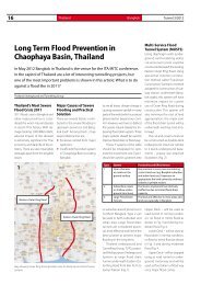
LIMMERN | SCHWEIZ<br />
PROJEKTDATEN AUFTRAGGEBER<br />
S-575<br />
Marti <strong>Tunnel</strong>bau AG<br />
Gripper-TBM<br />
Durchmesser: 5.200mm<br />
Schneidradleistung: 2.205kW<br />
<strong>Tunnel</strong>länge: 2x 1.030m<br />
Geologie: Quintnerkalk<br />
����������������<br />
�����������������<br />
���� �������������<br />
��� �����������<br />
�������������������������<br />
�������������������<br />
������������<br />
������������<br />
��������������<br />
���� � �������������<br />
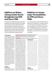
��� � �������������<br />
��� �������� �������������� ����� ���� ����������������� �������� �������� �������� ���� ������<br />
�������������������������������������������������������������������������������������<br />
�������������������������������������������������������������������������������������������<br />
����������������������������������������������������������������������������������������<br />
��������������������������������������������������������������������������������������<br />
�����������������������<br />
��������������������������������� �������������������������������������������������������<br />
����������������������������������������������������������������������������������������<br />
��������������������������������������������������������������������������������������������<br />
��� ������ ���������������� ����������� ����������� ����� ���������� ���� ������ ����������� �����<br />
�������������������������������������������������������������������������������������������<br />
���������������������������������������������������������������������������������������<br />
��������������������������������������������������������������������������������<br />
������������������������������������������������������������������������������������<br />
����������������������������������������������������������������������������������������������<br />
����������������������������
<strong>Tunnel</strong> 7/2011<br />
Offizielles Organ der<br />
www.stuva.de<br />
Title<br />
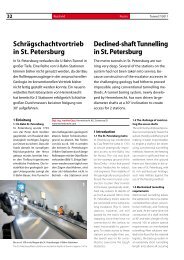
Einfache Aktivierung der Fluchtkammer<br />
Simple Activation of the refuge chamber<br />
(Photo: Dräger Safety AG & Co KGaA)<br />
Inhalt Contents<br />
1<br />
7/11<br />
Schrägschachtvortrieb für bis zu 100 m<br />
tief liegende U-Bahn-Stationen in<br />
St. Petersburg /Russland, Seite 32 ff.<br />
Inclined-shaft <strong>Tunnel</strong>ling for Metro stations<br />
located at depths of down to approx. 100 m in<br />
St. Petersburg / Russia, see pp 32.<br />
Aktuelles / Topical News 2<br />
Hauptbeiträge / Main Articles<br />
Stahlfaserspritzbeton im <strong>Tunnel</strong>bau: Stand der Technik und Beispiele 20<br />
Steel Fibre Shotcrete in <strong>Tunnel</strong>ling: State of the Art and Examples<br />
P. Guirguis<br />
Schrägschachtvortrieb in St. Petersburg 32<br />
Inclined-shaft <strong>Tunnel</strong>ling in St. Petersburg<br />
J. Gaus<br />
Pörzbergtunnel: Sicherheit durch Entrauchungstechnik 40<br />
Pörzberg <strong>Tunnel</strong>: Safety through Smoke Removal Technology<br />
STUVA-Nachrichten / STUVA News 44<br />
Aussteller STUVA-Tagung 2011/ Exhibitors STUVA Conference 2011 48<br />
Ihr Unternehmen auf der STUVA-Tagung ’11 in Berlin / D<br />
Your Company at STUVA Conference ’11 in Berlin / D<br />
Fachtagungen / Conferences<br />
Swiss <strong>Tunnel</strong> Congress 2011 60<br />
2011 Swiss <strong>Tunnel</strong> Congress<br />
Sanierung / Redevelopment<br />
Spritzbetonsanierung eines historischen U-Bahnhofs 63<br />
Redevelopment of the ceiling of the historic Metro Station<br />
Baumaschinen / Construction Equipment<br />
Thirra-Autobahn-<strong>Tunnel</strong> gesichert 67<br />
Thirra Highway <strong>Tunnel</strong> secured<br />
Abdichtung / Sealing<br />
<strong>Tunnel</strong>abdichtung in Fernost 69<br />
<strong>Tunnel</strong> sealing in the Far East<br />
Informationen / Information<br />
Buchbesprechung / Book Review 47<br />
Veranstaltungen / Events 71<br />
Inserentenverzeichnis / Advertising list 72<br />
Impressum / Imprint 72
2 Nachrichten<br />
News <strong>Tunnel</strong> 7/2011<br />
6. IUT ’11 in Sargans/CH<br />
IUT’11 wieder Treffpunkt<br />
der <strong>Tunnel</strong>bauer<br />
Ihren hohen Stellenwert<br />
als Branchentreff und <strong>Tunnel</strong>baumesse<br />
mit vielfältigem<br />
Angebot hat die Innovation<br />
unter Tage auch in 2011 nach<br />
Aussteller- und Besucher-<br />
Meinung wieder bestätigt.<br />
So konnte die 6. IUT mit rd.<br />
3.000 Besuchern im Versuchs-<br />
Stollen Hagerbach (VSH) in<br />
der Schweiz eine erfolgreiche<br />
Bilanz ziehen. Sehr zufrieden<br />
äußerten sich auch die rd. 100<br />
Unternehmen über die optimale<br />
Ausstellungsgröße, die<br />
Sonderschau Licht und Farbe<br />
und das Präsentationsforum.<br />
Von vielen speziell geschätzt<br />
wurde der Besuch der Delegation<br />
von brasilianischen <strong>Tunnel</strong>fachleuten,<br />
den die Arge<br />
IUT arrangiert hatte.<br />
Die Pflege von Kundenkontakten,<br />
die Präsentation von<br />
Innovationen, der Austausch<br />
und das Gespräch unter Fachleuten<br />
und Freunden standen<br />
im Fokus der Veranstaltung.<br />
Das Angebot an Kommuni-<br />
kationsmöglichkeiten war<br />
von den Organisatoren, der<br />
Arge IUT, absichtlich breit<br />
gefächert. Dazu gehörte der<br />
Messebesuch an den Ständen<br />
der Unternehmen, die<br />
ihre Produkte, Verfahren und<br />
Dienstleistungen aus vielen<br />
Bereichen des <strong>Tunnel</strong>baus<br />
vorstellten. Oder die Teilnahme<br />
an einem Firmenvortrag<br />
im Rahmen des Präsentations-Forums,<br />
wo Projekte<br />
und Produkte der Unternehmen<br />
vorgestellt und erläutert<br />
wurden. Auf großes Interesse<br />
stieß dabei die Präsentation<br />
der brasilianischen Delegation<br />
über den <strong>Tunnel</strong>baumarkt<br />
ihres Landes.<br />
Am Nachmittag des 14.<br />
und am Vormittag des 15.<br />
September 2011 fand das<br />
<strong>Tunnel</strong>bau-Seminar mit ausgewählten<br />
Experten statt.<br />
Unter der Leitung von Dr.-Ing.<br />
Roland Leucker von der STUVA<br />
wurde das Thema „<strong>Tunnel</strong>sanierung,<br />
-instandsetzung und<br />
6 th IUT ΄11 in Sargans/CH<br />
IUT ’11 again the Meeting Point<br />
for <strong>Tunnel</strong>lers<br />
Both exhibitors and visitors<br />
were again of the opinion that<br />
Innovation Underground was<br />
once again able to prove itself<br />
as a focal point for the industry<br />
together with the accompanying<br />
fair with all it had to offer in<br />
2011. Consequently the 6th IUT<br />
with some 3,000 visitors in the<br />
Hagerbach Test Gallery (VSH) in<br />
Switzerland was able to draw a<br />
successful balance. The around<br />
100 companies involved expressed<br />
their great satisfaction<br />
with the optimal size of the exhibition,<br />
the special Light and Colour<br />
show and the Presentation<br />
Forum. Many were particularly<br />
impressed by the visit of Brazilian<br />
tunnel experts arranged by the<br />
IUT joint venture.<br />
The event centred on improving<br />
contacts with customers, presenting<br />
innovations, exchanging<br />
views with other experts and<br />
friends. The organisers, the IUT<br />
JV intentionally provided a wide<br />
range of possibilities to communicate.<br />
These included visits to the<br />
company stands, where products,<br />
processes and services from many<br />
fields of tunnelling were presented.<br />
Or participation at lectures presented<br />
by a company within the scope<br />
of the Presentation Forum, where<br />
projects and products were put forward<br />
and discussed. In this connection<br />
great interest was shown in the<br />
presentation by the Brazilian delegation<br />
relating to the tunnelling<br />
market in their country.<br />
In the afternoon of September<br />
14th and the morning<br />
of the 15th a tunnelling seminar<br />
with selected experts took<br />
place. Chaired by Dr.-Ing. Roland<br />
Leucker of STUVA the topic of<br />
“<strong>Tunnel</strong> Redevelopment, Maintenance<br />
and Renovation” was<br />
presented at the IUT ’11. In this<br />
connection various projects and<br />
applications from Germany, Austria<br />
and Switzerland dealing with<br />
the event’s main theme relating<br />
to road and rail were dealt with<br />
and intensively discussed.
���������<br />
�����������<br />
���������������<br />
������������������<br />
��������������������������������������������������������������������������������������������<br />
�������������������������������������������������������������������������������������������������<br />
�������������������������������������������������������������������������������������������������<br />
�������������������������������������������������������������������������������<br />
����������������������������������������������������
4 Nachrichten<br />
News <strong>Tunnel</strong> 7/2011<br />
-erneuerung“ auf der IUT ´11<br />
präsentiert. Vorgestellt und<br />
rege diskutiert wurden dabei<br />
ganz unterschiedliche Projekte<br />
und Anwendungen aus<br />
Deutschland, Österreich und<br />
der Schweiz zum Schwerpunkt<br />
der Veranstaltung im Bereich<br />
Schiene und Straße.<br />
Nicht zu übersehen mit<br />
T-Shirts in den leuchtend<br />
gelb-grünen Farben ihres<br />
Heimatlandes war die große<br />
brasilianische Delegation: Die<br />
Arbeitsgemeinschaft IUT hatte<br />
<strong>Tunnel</strong>fachleute aus Brasilien<br />
zum Besuch und zur Präsentation<br />
des <strong>Tunnel</strong>baumarktes<br />
Ihres Landes eingeladen. Rund<br />
40 Experten waren für 5 Tage<br />
in der Schweiz. Das Programm<br />
enthielt neben dem Besuch<br />
der Messe, der Teilnahme am<br />
<strong>Tunnel</strong>bau-Seminar und am<br />
IUT-Abend auch Fachexkursionen<br />
sowie ein Kulturprogramm.<br />
Vor allem der geführte<br />
Besuch der Delegation von<br />
Ständen der Aussteller und<br />
die Diskussion zwischen brasilianischen<br />
Teilnehmern und<br />
Unternehmensvertretern war<br />
ein besonderes Highlight und<br />
führte zu intensiven Kontakten.<br />
Die brasilianische Delegation<br />
setzte sich aus Vertretern<br />
der größten Bauunternehmen,<br />
Planern, Hochschulvertretern,<br />
Vertretern von Infrastruktur-<br />
Betreibern/Bauherren und<br />
Vertretern der Zulieferindustrie<br />
zusammen.<br />
Mit der Sonderschau „Licht<br />
und Farbe“ bot die Innovation<br />
unter Tage in 2011 erstmals<br />
eine besondere Ausstellung in<br />
der Ausstellung an: In einem<br />
gesonderten <strong>Tunnel</strong>abschnitt<br />
präsentierten Unternehmen<br />
moderne Beleuchtungsmittel<br />
und Farbanstriche. Es wurden<br />
neuartige Beleuchtungsmöglichkeiten<br />
durch verschiedene<br />
Installationen aufgezeigt und<br />
die gegenseitige Beeinflussung<br />
der neuen LED-Beleuchtungsmittel<br />
und der Materialoberflächen<br />
eindrücklich „vor Augen<br />
geführt“. Hier machte die Innovation<br />
unter Tage ihrem Namen<br />
alle Ehre!<br />
Nach einem langen Messetag<br />
oder zur Mittagspause<br />
nutzten viele Besucher und<br />
Aussteller die mit wireless<br />
LAN ausgestatteten Lounges<br />
als Treffpunkt zu Gesprächen,<br />
zu einer ruhigen Pause oder<br />
um ihre E-Mails zu checken.<br />
Und am 14. September 2011<br />
traf man sich nach der Ausstellung<br />
zum traditionellen<br />
IUT-Abend in einer großen<br />
Kaverne des VersuchsStollen<br />
Hagerbach.<br />
Nach zwei ereignis- und<br />
erfolgreichen Tagen war der<br />
Grundtenor bei Ausstellern<br />
wie Besuchern: Wir sehen uns<br />
wieder zur IUT’14 in Sargans.<br />
Impressionen der Innovation<br />
unter Tage, des Festabends<br />
und des Seminars finden Sie<br />
unter www.iut.ch.<br />
The large Brazilian delegation<br />
sporting their country’s colours<br />
in the form of bright yellow and<br />
green T-shirts certainly could not<br />
be overlooked: the IUT JV had invited<br />
experts in tunnelling from<br />
Brazil to pay a visit and provide<br />
a presentation of the tunnelling<br />
market in their country. Some<br />
40 experts were in Switzerland<br />
for 5 days. Apart from attending<br />
the Fair, the programme involved<br />
taking part in the <strong>Tunnel</strong>ling Seminar<br />
and the IUT Evening and<br />
excursions as well as a cultural<br />
programme. First and foremost<br />
the guided tour provided for<br />
the delegation of the exhibitors’<br />
stands and discussions<br />
between Brazilian participants<br />
and company representatives<br />
was a particular highlight promising<br />
long-term contacts. The<br />
Brazilian delegation constituted<br />
representatives of the biggest<br />
construction companies, planners,<br />
university representatives,<br />
representatives of infrastructure<br />
operators/clients and suppliers.<br />
For the first time in 2011 Innovation<br />
Underground presented a<br />
special fair within the fair – a show<br />
devoted to “Light and Colour”. In<br />
a special section of the complex<br />
various companies presented modern<br />
lighting facilities and colour<br />
coatings. First and foremost novel<br />
possibilities were shown and the<br />
influence of LED means of lighting<br />
demonstrated on material surfaces.<br />
A real boost for Innovation<br />
Underground as such!<br />
Following a protracted day<br />
at the fair or for a midday break,<br />
many visitors took avail of the<br />
lounges equipped with wireless<br />
either for chats, a brief break or<br />
check their E-mails. And on the<br />
evening of September 14, 2011<br />
the traditional IUT Evening, that<br />
unique get-together for tunnellers<br />
in a huge cavern at the<br />
Hagerbach Test Gallery, took<br />
place after the exhibition.<br />
Following 2 eventful and<br />
successful days the basic feeling<br />
among both exhibitors and visitors<br />
was: we’ll be back in Sargans<br />
for the IUT ’14. You can access<br />
impressions of Innovation Underground,<br />
the Gala Evening and<br />
the Seminar at www.iut.ch.
GROUND CONTROL<br />
SOLUTIONS<br />
Each tunnel has a different geology and requires specific customized products and systems.<br />
DSI <strong>Tunnel</strong>ing Products and Systems match these requirements perfectly.<br />
Our extensive R&D activities guarantee innovative, flexible and reliable underground support<br />
products to control every imaginable condition. We offer a complete line of high-quality ISO<br />
9001: 2000 certified and patented products. DSI is leading in the development, production<br />
and application of ground control solutions to the tunneling market. In line with our strong<br />
service approach, we are always committed to satisfying our customers’ demands.<br />
DSI is global market leader in the development, production and application of<br />
Post-Tensioning and Geotechnical Systems as well as Concrete Accessories for the<br />
Construction industry. DSI is also the leading supplier of Ground Control Solutions for the<br />
Mining and <strong>Tunnel</strong>ing industry worldwide.<br />
EMEA<br />
Austria<br />
www.dywidag-systems.at<br />
Local Presence – Global Competence<br />
www.dsi-tunneling.com<br />
South America<br />
Chile<br />
www.dsi-chile.com<br />
North America<br />
USA<br />
www.dsiunderground.com<br />
New System Solution for <strong>Tunnel</strong>ing:<br />
DYWI ® Inject Systems<br />
THREADBAR® Anchors<br />
Rebar Rock Bolts and Spiles<br />
DYWI® Drill Hollow Bar Bolts and<br />
IBO Self-Drilling Spiles<br />
OMEGA-BOLT®<br />
Expandable Friction Bolt<br />
AT - POWER SET Self-Drilling<br />
Friction Bolt<br />
DYWIDAG Rock Bolts and Soil Nails<br />
Mortar-Mixing Pumps<br />
Steel Arches and TH-Beams<br />
Liner Plates<br />
PANTEX Lattice Girders<br />
AT - LSC TM Element<br />
(Lining Stress Controller)<br />
AT – Pipe Umbrella Support System<br />
AT – Drainage System<br />
AT – GRP Injection System<br />
DYWI® Inject Systems<br />
DSI Waterproofing System<br />
APAC (ASEAN)<br />
Australia<br />
www.dsiminingproducts.com/au
6 Nachrichten<br />
News <strong>Tunnel</strong> 7/2011<br />
Schweiz<br />
Ausbau und Tiefl egung<br />
der Zentralbahn Luzern<br />
Die meterspurige Zentralbahn<br />
(zb) erhält in Luzern mit dem<br />
zweigleisigen Ausbau und der<br />
Tiefl egung eine leistungsfähigere<br />
Infrastruktur mit einigen<br />
<strong>Tunnel</strong>bauwerken. Dadurch wird<br />
die Voraussetzung für ein attraktives<br />
Angebot zwischen Luzern<br />
und Engelberg bzw. Interlaken<br />
geschaffen. Außerdem trägt<br />
ihre Tiefl egung in Luzern zum<br />
Verringern der Verkehrsbehinderungen<br />
und weniger Lärmemissionen<br />
in der Stadt bei. Gleichzeitig<br />
wird für die Besucher der<br />
Messe Allmend und des im Bau<br />
befindlichen Fußballstadions<br />
eine Haltestelle geschaff en.<br />
Images: Implenia Bau AG<br />
1<br />
Zum 1465 m langen, zweigleisigen<br />
Ausbau und Tiefl egung<br />
der zb in Luzern (Bild 1) gehören<br />
• der bergmännisch erstellte,<br />
554 m lange Hubelmatttunnel<br />
einschließlich des 42 m<br />
langen Tagbautunnel Geissenstein,<br />
• die 296 m lange, mit 3 Zugängen<br />
erschlossene, unterirdische<br />
Haltestelle Allmend<br />
mit Mittelbahnsteig,<br />
• der 471 m lange Tagbautunnel<br />
Allmend in Deckelbauweise<br />
und<br />
• die 144 m lange Rampe Mattenhof.<br />
Switzerland<br />
Development and Lowering of the<br />
Lucerne Zentralbahn<br />
The metre-gauge Zentralbahn<br />
(zb) is being provided with a more<br />
effi cient infrastructure with several<br />
tunnels in Lucerne in the form<br />
of a twin-track development and<br />
lowering the station facility. In this<br />
way the prerequisite for an attractive<br />
schedule between Lucerne<br />
and Engelberg and Interlaken<br />
is to be provided. Furthermore<br />
the lowering of the station in Lucerne<br />
will help reduce hindrances<br />
to traffi c and create fewer noise<br />
emissions in the city. At the same<br />
time a stop is to be provided<br />
for visitors to the Allmend fairgrounds<br />
and the football stadium<br />
currently being built.<br />
Ausbau und Tiefl egung der Zentralbahn (zb) Luzern – Projekt-Übersicht mit den verschiedenen <strong>Tunnel</strong>bauwerken<br />
Development and lowering of the Zentralbahn (zb) in Lucerne – project overview with the various tunnels<br />
The 1,465 m long, twin-track<br />
development and lowering of<br />
the zb in Lucerne constitutes<br />
(Fig. 1):<br />
• the 554 m long Hubelmatt<br />
<strong>Tunnel</strong>, produced by mining<br />
means including the 42 m<br />
long Geissenstein <strong>Tunnel</strong> built<br />
by cut-and-cover,<br />
• the 296 m long Allmend underground<br />
station with a central<br />
platform and 3 accesses,<br />
• the 471 m long Allmend <strong>Tunnel</strong><br />
produced by cut-and-cover<br />
employing the top cover<br />
method and<br />
• the 144 m long Mattenhof<br />
ramp.
RELIABLE � RESPONSIVE<br />
���ROBBINS�����������<br />
WHY SETTLE FOR A DISMANTLED TBM?<br />
���������������������������������������������������������������<br />
�����������������������������������������������������������<br />
���������������������������������������������������������������<br />
�����������������������������������������������������������������<br />
���������������������������������������������������������������
8 Nachrichten<br />
News <strong>Tunnel</strong> 7/2011<br />
Zu diesem Projekt kommen<br />
weitere bauliche Maßnahmen<br />
(Bild 2), wie der zweigleisige<br />
Ausbau von Hergiswill in einem<br />
langen <strong>Tunnel</strong> und Beschleunigungsmaßnahmen<br />
auf dem<br />
Streckennetz.<br />
Hubelmatttunnel<br />
Für diesen zweigleisigen <strong>Tunnel</strong><br />
wurde ein setzungsarmer<br />
Bauablauf mit aufgeteiltem<br />
Ausbruchquerschnitt gewählt.<br />
Die Bauarbeiten begannen<br />
mit dem Abtiefen der Baugruben<br />
an den beiden Portalen.<br />
<strong>Tunnel</strong> und Voreinschnitte<br />
liegen in unterschiedlich verwittertem<br />
Felsen der Süßwassermolasse<br />
unter einer mächtigen<br />
Lockergesteinsschicht.<br />
Auf der Seite Allmend wurde<br />
von einem 25 m langen Vorstollen<br />
aus mit einer offenen<br />
Bohrmaschine ein Erkundungsstollen<br />
(3,90 m Durchmesser)<br />
im <strong>Tunnel</strong>scheitel aufgefahren<br />
(Bild 1). Er diente zum Absaugen<br />
des beim nachfolgenden<br />
Kalottenausbruch mit einer Teilschnittmaschine<br />
(3 - 3,5 m/AT)<br />
entstehenden Staubes; das Gerät<br />
verlädt auch den Ausbruch<br />
über ein Förderband auf Lkw.<br />
Nach dem Kalottenausbruch<br />
wird vom Südportal aus die<br />
Strosse ausgebaut. Der Ausbruchquerschnitt<br />
ist bei 95<br />
m2 rd. 11,50 m breit und rd.<br />
10,30 m hoch. Gesichert wird<br />
der <strong>Tunnel</strong> mit Spritzbeton<br />
und Fels-ankern. Abschließend<br />
erhält er eine Ortbetoninnenschale.<br />
Allmendtunnel<br />
Der zweigleisige Allmendtunnel<br />
und der südliche Teil der<br />
Haltestelle Allmend (Bild 1)<br />
wurden nach einem Sondervorschlag<br />
in Deckelbauweise<br />
unter Druckluft erstellt und<br />
dadurch die Bauzeit auf etwa 8<br />
Zentralbahn (zb) Luzern mit baulichen Maßnahmen für eine leistungsfähigere<br />
Infrastruktur<br />
Zentralbahn (zb) Lucerne with structural measures for a more effective<br />
infrastructure<br />
Monate verkürzt, die Baukosten<br />
verringert und die Umwelt weniger<br />
beeinträchtigt. Im Bereich<br />
der Druckluftstrecke stehen<br />
Seebodenablagerungen aus<br />
tonigen, teilweise sandigen<br />
Schluffen mit organischen<br />
und sandigen Einlagerungen<br />
an. Der obere Grundwasserspiegel<br />
liegt etwa in Höhe der<br />
<strong>Tunnel</strong>decke; außerdem gibt es<br />
einen zweiten, tiefer liegenden,<br />
gespannten Grundwasserträger,<br />
so dass der <strong>Tunnel</strong> vollständig<br />
im Grundwasser liegt.<br />
Bei der Deckelbauweise unter<br />
Überdruck wird der seitliche<br />
Baugrubenabschluss durch<br />
Spundwände sichergestellt, die<br />
nachher wieder gezogen werden.<br />
Nach einem Voraushub<br />
wird darauf die <strong>Tunnel</strong>decke<br />
betoniert und für die Aushubarbeiten<br />
darunter ein entsprechender<br />
Überdruck erzeugt; er<br />
2<br />
The project includes further<br />
structural measures (Fig. 2) such<br />
as the twin-track development<br />
of Hergiswill in a long tunnel and<br />
speed-up measures on the rail<br />
network.<br />
Hubelmatt <strong>Tunnel</strong><br />
A construction cycle causing minimal<br />
settlement with a divided<br />
excavated cross-section was selected<br />
for this twin-track tunnel.<br />
The construction activities started<br />
by deepening the pits at the<br />
2 portals. The tunnel and pre-cuts<br />
are located in differently weathered<br />
sweet water molasse rocks<br />
under a thick layer of soft ground.<br />
An exploratory tunnel (3.90 m diameter)<br />
was driven in the tunnel<br />
apex (Fig. 1) on the Allmend side<br />
from a 25 m long access tunnel<br />
using an open boring machine.<br />
It served to suction off the dust<br />
resulting from the subsequent<br />
crown excavation produced<br />
by a roadheader (3 – 3.5 m per<br />
working day); the machine also<br />
loaded the extracted material<br />
on to lorries via a conveyor belt.<br />
Following the crown excavation<br />
the bench is developed from the<br />
south portal. The excavated crosssection<br />
of roughly 95 m2 is some<br />
11.50 m wide and approx. 10.30 m<br />
high. The tunnel is secured with<br />
shotcrete and rock bolts. Then it is<br />
provided with an in situ concrete<br />
inner shell.<br />
Allmend <strong>Tunnel</strong><br />
The twin-track Allmend <strong>Tunnel</strong><br />
and the southern part of<br />
the Allmend stop (Fig. 1) were<br />
produced by a special proposal<br />
using the top cover method with<br />
compressed air so that the construction<br />
period was reduced to<br />
around 8 months, the construction<br />
costs lowered and the<br />
environment substantially less<br />
affected. Marine deposits consisting<br />
of clayey, partially sandy silts<br />
with organic and sandy intrusions<br />
are located in the compressed air<br />
sector. The upper groundwater<br />
table is located at roughly tunnel<br />
ceiling height; in addition there<br />
is a second zone of artesian<br />
water located further down so<br />
that the tunnel is to be found<br />
completely in the groundwater.<br />
For the top cover method employing<br />
compressed air the excavation<br />
pit closure at the sides<br />
is secured by piling walls, which<br />
are subsequently removed. The<br />
tunnel ceiling is concreted on an<br />
advance excavation and a corresponding<br />
overpressure produced<br />
for the excavation work<br />
progressing underneath; depending<br />
on the depth the pressure<br />
amounts to between 0.57 and<br />
0.68 bar. Gravel is deposited to<br />
weigh down the tunnel ceiling<br />
so that it does not lift on account<br />
of the overpressure.
<strong>Tunnel</strong> 7/2011<br />
liegt je nach Tiefenlage zwischen<br />
0,57 und 0,68 bar. Mit<br />
einer zusätzlichen Kiesschüttung<br />
als Auflast verhinderte<br />
man, dass sich die <strong>Tunnel</strong>decke<br />
infolge des Überdrucks<br />
anhebt.<br />
Druckluftbetrieb<br />
Am Ende der Rampe Mattenhof<br />
wurde der <strong>Tunnel</strong>querschnitt<br />
(10 x 8 m) mit einer Betonwand<br />
abgeschlossen und<br />
darin eine Material- und Personenschleuse<br />
für den Druckluftbetrieb<br />
eingebaut. Darin<br />
müssen sich alle Personen vor<br />
dem Eintritt in den <strong>Tunnel</strong> an<br />
den höheren Druck im <strong>Tunnel</strong><br />
anpassen; dasselbe gilt nach<br />
Arbeitsende (Dekompression).<br />
Die im Druckluftbetrieb<br />
arbeitenden Personen waren<br />
vorher von der Schweizer Unfallversicherungsanstalt<br />
(Suva)<br />
auf ihre Drucklufttauglichkeit<br />
untersucht worden.<br />
Aus Brandschutzgründen<br />
werden alle Maschinen mit<br />
Elektromotoren betrieben,<br />
wie 2 Bagger für die Aushubarbeiten,<br />
Förderbänder und<br />
die Stollenbahn für den Materialtransport.<br />
Der Beton für die<br />
Bodenplatte und die Wände<br />
wurde von außen in den <strong>Tunnel</strong><br />
gepumpt. – Der Druckluftbetrieb<br />
konnte erfolgreich Ende<br />
2010 abgeschlossen werden.<br />
Haltestelle Allmend<br />
Da sich im Haltestellenbereich<br />
wegen des Mittelbahnsteiges<br />
der <strong>Tunnel</strong>querschnitt auf<br />
eine Breite von bis zu 18,2 m<br />
aufweitet (Bild 1), wurden als<br />
Bauhilfsmaßnahme für die<br />
Mittelabstützung der <strong>Tunnel</strong>decke<br />
vorgängig Bohrpfähle<br />
abgeteuft, denn die Mittelstützen<br />
können erst nach dem Erstellen<br />
der Bodenplatte darauf<br />
betoniert werden.<br />
News<br />
Compressed Air<br />
Operation<br />
At the end of the Mattenhof ramp<br />
the tunnel cross-section (10 x 8 m)<br />
was concluded with a concrete<br />
wall and a material and manlock<br />
installed for the compressed air<br />
operation. All those involved had<br />
to adapt to the higher pressure in<br />
the tunnel within this lock prior<br />
to entering the tunnel; the same<br />
applied after completing work<br />
(decompression). Persons engaged<br />
in the compressed air operation<br />
were first of all examined<br />
by the Swiss Accident Insurance<br />
Institute (SUVA) to determine their<br />
suitability for working under compressed<br />
air.<br />
All machines are driven by<br />
electric motors for fire protection<br />
reasons – such as 2 excavators for<br />
excavation work, conveyor belts<br />
and the tunnel railway for transporting<br />
material. The concrete for<br />
the base slab and the walls was<br />
pumped into the tunnel from<br />
the outside. The compressed air<br />
operation was successfully concluded<br />
at the end of 2010.<br />
Allmend Stop<br />
Bored piling was first of all sunk as<br />
an ancillary construction measure<br />
for the central support as the<br />
tunnel cross-section had to be<br />
extended to a width of as much<br />
as 18.2 m (Fig. 1) on account of<br />
the central platform in the area of<br />
the stop for the central supports<br />
can first be concreted on the<br />
base slab after it is produced.<br />
Construction Times<br />
and Costs<br />
The first clod was turned on<br />
December 9, 2008. After construction<br />
began in May 2009<br />
the Hubelmatt <strong>Tunnel</strong> is due to<br />
be concluded in May 2011 whereas<br />
the driving operations for<br />
the Allmend <strong>Tunnel</strong> and parts<br />
of the Allmend stop lasted from<br />
The future<br />
of mobility<br />
InnoTrans 2012<br />
Internationale Fachmesse für Verkehrstechnik<br />
Innovative Komponenten · Fahrzeuge · Systeme<br />
18. – 21. September · Berlin<br />
www.innotrans.de<br />
Messe Berlin GmbH · Messedamm 22 · 14055 Berlin<br />
Tel. +49(0)30/3038-2376 · Fax +49(0)30/3038-2190<br />
innotrans@messe-berlin.de
10 Nachrichten<br />
News <strong>Tunnel</strong> 7/2011<br />
Bauzeiten und Bau-<br />
kosten<br />
Am 9. Dezember 2008 war<br />
der erste Spatenstich. Nach<br />
Baubeginn im Mai 2009 wird<br />
der Hubelmatttunnel im Juni<br />
2011 aufgefahren sein, während<br />
die Vortriebsarbeiten<br />
am Allmendtunnel und Teilen<br />
der Haltestelle Allmend<br />
vom 10. Februar bis 26. Oktober<br />
2010 dauerten. Ab Ende<br />
2011 beginnt der Einbau der<br />
Bahntechnik (Gleise, Fahrleitung,<br />
Signalanlagen) auf der<br />
gesamten Neubaustrecke.<br />
Die Inbetriebnahme ist zum<br />
Fahrplanwechsel 2013 vorgesehen.<br />
Für die Baumaßnahmen werden<br />
insgesamt 45.000 m3 Beton<br />
und 7.000 t Bewehrung,<br />
4.100 m2 Spritzbeton mit 700 m<br />
Felsankern, 27.000 m2 Spundwände<br />
und 7.200 m Bohrpfähle<br />
benötigt. Es fallen 0,28 Mio. m3<br />
Aushub an.<br />
Man rechnet mit Investitionskosten<br />
von insgesamt 250<br />
Mio. CHF (180 Mio. EUR); sie<br />
werden zur Hälfte vom Bund<br />
getragen, den Restbetrag<br />
bringen die Kantone Luzern,<br />
Nidwalden, Obwalden und<br />
die Stadt Luzern auf. Der Bund<br />
steuert seinen Beitrag über den<br />
Infrastrukturfond bei. G.B.<br />
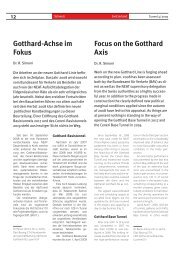
Österreich/Italien<br />
<strong>Brenner</strong> Basistunnel:<br />
Zulaufstrecken und <strong>Tunnel</strong>anschlag<br />
Der 55 km lange <strong>Brenner</strong> Basistunnel<br />
(BBT) ist das Kernstück<br />
der Neubaustrecke München-<br />
Verona im Transeuropäischen<br />
Netz (TEN) und soll 2025 in Betrieb<br />
gehen; er wird voraussichtlich<br />
8,2 Mrd. EUR kosten, wovon<br />
die Europäische Union (EU) 27 %<br />
übernimmt; die übrigen Kosten<br />
teilen sich Österreich und Italien.<br />
Zum BBT gehört der Bau<br />
von Zulaufstrecken im Norden<br />
(Neue Unterinntalbahn) und<br />
Süden zwischen Franzensfeste<br />
und Verona.<br />
Von der neuen südlichen<br />
Zulaufstrecke des BBT wird die<br />
am 18. November 2010 vom<br />
Komitee für wirtschaftliche<br />
Planung (CIPE) beschlossene<br />
Projektierung des Bauloses 1<br />
Anfang Februar 2013 vorliegen:<br />
die Strecke zwischen Franzensfeste<br />
und Waidbruck wird aus<br />
dem 15,5 km langen Schalderertunnel<br />
und dem 5,9 km lan-<br />
gen Grödenertunnel bestehen;<br />
die größte Herausforderung bedeutet<br />
in Waidbruck wegen der<br />
beschränkten Platzverhältnisse<br />
und der sicherheitstechnischen<br />
Auflagen die Anbindung an<br />
den Schlerntunnel. Für die<br />
Finanzierung dieser Baumaßnahme<br />
wurden 1,618 Mrd. EUR<br />
freigegeben.<br />
Für das Baulos 2, die Umfahrung<br />
Bozen, wird die endgültige<br />
Projektierung Anfang 2015 vorliegen<br />
und die CIPE-Genehmigung<br />
Anfang 2016. Ähnlich ist<br />
der Sachverhalt bei Baulos 3,<br />
der 42 km langen Umfahrung<br />
zwischen Trient und Rovereto,<br />
(Ende 2014/Herbst 2015) und<br />
beim Baulos 4 im Bereich Verona<br />
(2013/August 2014). – Der Zeitplan<br />
wurde auf die Inbetriebnahme<br />
des BBT abgestimmt.<br />
Die Arbeiten an der neuen<br />
Unterinntalbahn – davon<br />
32 km in <strong>Tunnel</strong>n - schreiten<br />
February 10 to October 26, 2010.<br />
The rail technological equipment<br />
(tracks, contact wire, signal units)<br />
will be installed along the entire<br />
new route as from the end of 2011.<br />
The project is scheduled to be<br />
opened when the new timetable<br />
is introduced in 2013.<br />
Altogether 45,000 m3 of concrete<br />
and 7,000 t of reinforcement,<br />
4,100 m2 of shotcrete with 700 m<br />
of rock bolts, 27,000 m2 of piling<br />
walls and 7,200 m of bored piles<br />
were needed for the construction<br />
measure. 0.28 mill. m3 of excavation<br />
material will result.<br />
Investment costs of altogether<br />
250 mill. CHF (180 mill. euros) will<br />
ensue; half this total will be borne<br />
by the state, the remaining amount<br />
will be contributed by the cantons<br />
of Lucerne, Nidwalden, Obwalden<br />
and the City of Lucerne. The state’s<br />
contribution will come from the<br />
Infrastructural Fund. G.B.<br />
Literatur/References<br />
[1] Peyer, W.: Allmendtunnel – Durchstich im Druckluftverfahren.<br />
SchweizerBauJournal-Infrastruktur (Aarau) 6/2010, pp. 35 - 37<br />
[2] Kohlschreiber, Ch.: Überdruck unter Luzern. TEC21 (SIA; Zürich) 49-<br />
50/2010, pp. 23 - 25<br />
Austria/Italy<br />
<strong>Brenner</strong> <strong>Base</strong> <strong>Tunnel</strong>:<br />
Access Routes and <strong>Tunnel</strong> Start-Up<br />
The 55 km long <strong>Brenner</strong> <strong>Base</strong><br />
<strong>Tunnel</strong> (BBT) represents the<br />
core of the new Munich-Verona<br />
route on the trans-European network<br />
(TEN) and is due to open<br />
in 2025. It is estimated to cost<br />
8.2 b. euros of which the European<br />
Union will contribute 27 %<br />
of the total with Austria and Italy<br />
sharing the remainder. The BBT<br />
project includes the building of<br />
access routes in the north (New<br />
Lower Inn Valley Railway) and<br />
south between Franzenfeste<br />
and Verona. The planning for<br />
contract section 1 of the new<br />
BBT southern access route,<br />
which was decided on by the<br />
Committee for Economic Planning<br />
(CIPE) will be available at<br />
the beginning of February 2013.<br />
The route between Franzenfeste<br />
and Waidbruck will comprise<br />
the 15.5 km long Schalder <strong>Tunnel</strong><br />
and the 5.9 km long Gröden<br />
<strong>Tunnel</strong>; the greatest challenge<br />
is presented in Waidbruck by<br />
linking up to the Schlern <strong>Tunnel</strong><br />
on account of restricted space<br />
conditions and safety technical<br />
regulations. 1.618 b. euros has<br />
been earmarked for financing<br />
this construction measure.<br />
For contract section 2, bypassing<br />
Bozen, the final planning<br />
will be available at the beginning<br />
of 2015 and CIPE approval early<br />
2016. The same situation applies<br />
to contract section 3, the 42 km<br />
long bypass between Trient and<br />
Rovereto (late 2014/autumn 2015)<br />
and to contract section 4 in the<br />
Verona area (2013/August 2014).<br />
– The timetable has been geared<br />
to the commissioning of the BBT.<br />
Work on the new Lower Inn<br />
Valley Railway – 32 km of which<br />
lies in tunnels – is progressing:<br />
every week 1 km of new track,<br />
every month a new shaft head<br />
building achieved by the suppliers<br />
in order to ensure that the
<strong>Tunnel</strong> 7/2011<br />
voran: jede Woche 1 km neues<br />
Gleis, jeden Monat ein neues<br />
Schachtkopfgebäude als Arbeitsleistung<br />
der Ausrüster, um<br />
die technischen Anlagen zwischen<br />
Kundl und Baumkirchen<br />
zeitgerecht fertig zu stellen;<br />
mehr als 40 km Fahrweg sind<br />
schon eingebaut und die ersten<br />
Testfahrten beginnen. Ende<br />
2012 ist die fahrplanmäßige Inbetriebnahme<br />
vorgesehen. Alle<br />
Bauabläufe liegen im Zeitplan.<br />
– Gut auf der Schiene sind auch<br />
die Umweltmaßnahmen: 24 km<br />
Masse-Feder-Systeme sind bereits<br />
hergestellt.<br />
Nach der ersten Sprengung<br />
für den Zufahrttunnel<br />
Wolf bei Steinach/<strong>Brenner</strong> am<br />
8. April 2011 wurde die dritte<br />
große Baustelle auf der österreichischen<br />
Seite des BBT be-<br />
Nachrichten News<br />
11<br />
KrampeHarex ® Zeit für Lösungen<br />
Stahl- und Kunststofffasern<br />
<strong>Tunnel</strong>bau<br />
Schneller: Besser: Wirtschaftlicher:<br />
Bis zu 2,5-mal schneller als bei<br />
konventioneller Betonstahlbewehrung.<br />
gonnen. Der <strong>Tunnel</strong> wird im<br />
konventionellen Vortrieb in<br />
Teilausbrüchen aufgefahren<br />
und hat 104 m2 Ausbruchquerschnitt.<br />
Von der Baustelle Wolf<br />
zweigt nach der Unterquerung<br />
der bestehenden Eisenbahnlinie<br />
der über 700 m lange Padastertunnel<br />
ab zum Abtransport<br />
des Ausbruchmaterials zur<br />
Deponie im Padastertal. Im Mai<br />
2011 wurden die Vortriebe des<br />
Padastertunnels vom Padastertal<br />
aus und des 1003 m langen<br />
Saxenertunnels von Wolf aus<br />
begonnen; damit gibt es allein<br />
auf dieser Baustelle gleichzeitig<br />
3 <strong>Tunnel</strong>vortriebe. – Zur selben<br />
Zeit verlegt die <strong>Brenner</strong> Basistunnel<br />
Gesellschaft (BBT SE) die<br />
Trinkwasseranlage im Padastertal.<br />
G.B.<br />
Fasern erhöhen Betonfestigkeiten<br />
und den Brandschutz.<br />
technical installations between<br />
Kundl and Baumkirchen are ready<br />
in time. More than 40 km of<br />
track has already been installed<br />
and the first trial runs are beginning.<br />
Operations are due to start<br />
in keeping with the timetable at<br />
the end of 2012. All construction<br />
phases are up to schedule. The<br />
same applies to the measures<br />
for protecting the environment:<br />
24 km of mass-spring systems<br />
have already been produced.<br />
The third large construction<br />
site on the Austrian side<br />
of the BBT began on April 8,<br />
2011 after the initial blasting<br />
for the Wolf access tunnel near<br />
Steinach/<strong>Brenner</strong>. The tunnel is<br />
being driven conventionally in<br />
part-excavations and possesses<br />
104 m2 excavated cross-section.<br />
After underpassing the existing<br />
railway line the more than 700 m<br />
long Padaster <strong>Tunnel</strong> forks off<br />
from the Wolf construction site<br />
for transporting the excavated<br />
material to the dump in the Padastertal.<br />
In May 2011 the drives<br />
for the Padaster <strong>Tunnel</strong> began<br />
from the Padastertal and the<br />
1,003 m long Saxen <strong>Tunnel</strong> from<br />
Wolf. As a result there are now no<br />
less than 3 drives operating on<br />
this site. – At the same time the<br />
<strong>Brenner</strong> Basistunnel Gesellschaft<br />
(BBT SE) is engaged in relocating<br />
the drinking water facility in the<br />
Padastertal. Towards this end a<br />
new elevated tank is being set<br />
up and a new pressure pipeline<br />
laid, which will run through a 500<br />
m long tunnel specially built for<br />
the purpose in the steep hilly<br />
terrain. G.B.<br />
Geringere Material- und Lohnkosten sorgen<br />
für Vorteile in Kalkulation und Angebot.<br />
KrampeHarex GmbH & Co. KG · 59075 Hamm · Tel. +49 (0) 23 81 .9 77 977 · Fax +49 (0) 23 81 .9 77 955 · info@krampeharex.com · www.krampeharex.com
12 Nachrichten<br />
News <strong>Tunnel</strong> 7/2011<br />
Deutschland<br />
Durchschlag beim <strong>Tunnel</strong> Bleßberg<br />
Mit 8314 m ist der zweigleisige<br />
Bleßbergtunnel der längste<br />
<strong>Tunnel</strong> der Neubaustrecke<br />
Ebensfeld-Erfurt, des Schienenverkehrsprojekts<br />
Deutsche<br />
Einheit Nr. 8 (VDE 8.1) und wird<br />
nach seiner Inbetriebnahme der<br />
drittlängste zweigleisige Eisenbahntunnel<br />
in Deutschland<br />
sein. Der <strong>Tunnel</strong> unterquert bei<br />
einer Überdeckung bis zu 330 m<br />
den Hauptkamm des Thüringer<br />
Waldes zwischen Truckenthal<br />
und Goldisthal; er wurde am 29.<br />
Juni 2011 durchgeschlagen.<br />
Das Südportal liegt auf einer<br />
Höhe von 502 m über NN, das<br />
Nordportal bei 1,09 % Steigung<br />
auf 593 m. Der Eisenbahntunnel<br />
hat eine lichte Höhe von 8,23 m<br />
über Schienenoberkante (SOK)<br />
und eine lichte Weite von 13,64<br />
m bei einem Kreisprofil mit 92<br />
m2 Nutzungsquerschnitt. Der<br />
Ausbruchquerschnitt betrug<br />
rd. 130 m2, was etwas 1,8 Mio m3<br />
Ausbruchmaterial ergab.<br />
Der <strong>Tunnel</strong> wurde bergmännisch<br />
im Sprengvortrieb mit<br />
Spritzbetonausbau aufgefahren,<br />
und zwar von Süden auf 4,6 km<br />
Länge über einen 965 m langen<br />
Zwischenangriff und von Norden,<br />
wozu vorab zum Abtransport<br />
des Ausbruchmaterials<br />
anschließend die Saubachbrücke<br />
und der <strong>Tunnel</strong> Goldberg<br />
(1163 m) gebaut wurden.<br />
Der <strong>Tunnel</strong> Bleßberg hat 8<br />
Notausgänge mit Abständen<br />
von höchstens 1000 m, die mit<br />
Rettungsstollen (insgesamt<br />
4477 m), die teilweise parallel<br />
zum Haupttunnel verlaufen,<br />
und einem Aufzugschacht ins<br />
Freie führen. Eine durchgehende<br />
Löschwasserleitung ermöglicht<br />
die rasche Brandbekämpfung im<br />
ganzen <strong>Tunnel</strong>. Als Oberbau wird<br />
eine Feste Fahrbahn eingebaut<br />
und der Gleisabstand im <strong>Tunnel</strong><br />
beträgt 4,50 m und die Ausbaugeschwindigkeit<br />
300 km/h.<br />
An beiden <strong>Tunnel</strong>portalen<br />
werden aufgrund aerodynamischer<br />
Untersuchungen<br />
Bauwerke zum Ausgleich der<br />
Mikrowellenemission (Sonic<br />
boom) [4] errichtet. – Die Gesamtinvestition<br />
für den <strong>Tunnel</strong><br />
Bleßberg wird etwa 200 Mio.<br />
EUR betragen. G.B.<br />
Deutschland<br />
Sanierung des Schlüchterner <strong>Tunnel</strong>s<br />
Der Neue Schlüchterner <strong>Tunnel</strong><br />
ist fast 4 km lang und hat 9<br />
m Innendurchmesser; er wurde<br />
mit einer <strong>Tunnel</strong>vortriebsmaschine<br />
(TVM) im Abstand<br />
von 50 bis 90 m zum bestehenden<br />
<strong>Tunnel</strong> aufgefahren<br />
[1-4]. Ab 26. April 2011 wird<br />
Germany<br />
Breakthrough at Bleßberg <strong>Tunnel</strong><br />
The 8,314 m twin-track long Bleßberg<br />
<strong>Tunnel</strong> is the longest on the<br />
new Ebensfeld-Erfurt rail route<br />
– German Unity Rail Project No.<br />
8 (VDE 8.1) and once commissioned<br />
will be the third longest<br />
twin-track rail tunnel in Germany.<br />
With overburden of up to 230 m<br />
the tunnel underpasses the main<br />
reaches of the Thuringian Forest<br />
between Truckenthal and Goldisthal.<br />
The breakthrough took<br />
place on June 29, 2011.<br />
The south portal is located at<br />
only 502 m ASL, the north portal<br />
at 593 m given 1.09 % gradient.<br />
The rail tunnel possesses a clear<br />
height of 8.23 m above the upper<br />
edge of the rail and a clear<br />
width of 13.64 m given a circular<br />
profile of 92 m2 useful cross-section.<br />
The excavated cross-section<br />
amounts to roughly 130 m2,<br />
which resulted in around 1.8 m.<br />
m3 of excavated material.<br />
The tunnel was driven by mining<br />
means using drill+blast with<br />
shotcrete lining – from the north<br />
Literatur / References<br />
[1] <strong>Tunnel</strong>bau für die NBS Ebensfeld-Erfurt. <strong>Tunnel</strong> 4/2008, pp. 20-21<br />
[2] ICE-<strong>Tunnel</strong> Bleßberg im Thüringer Wald. <strong>Tunnel</strong> 2/2009, pp. 6 – 7<br />
[3] Feldwisch, W.; Drescher, O.; Flügel, M.; Lies. S.: Die <strong>Tunnel</strong> der Neu- und<br />
Ausbaustrecke Nürnberg-Erfurt-Leipzig/Halle. ETR 4/2010, pp. 186-196<br />
[4] Katzenbergtunnel: Besondere Portale verhindern <strong>Tunnel</strong>knall.<br />
<strong>Tunnel</strong> 2/2011, pp. 10 -12<br />
der Eisenbahnverkehr (260<br />
Züge/durchschnittlich) im<br />
Streckenabschnitt zwischen<br />
Fulda und Frankfurt am Main<br />
für die nächsten 3 Jahre durch<br />
den Neuen Schlüchterner<br />
<strong>Tunnel</strong> geführt. Während dieser<br />
Zeit wird der zweigleisige<br />
over 4.6 km via a 965 m long intermediate<br />
point of attack and<br />
from the south, towards which<br />
end the Saubach Bridge and the<br />
Goldberg <strong>Tunnel</strong> (1,163 m) were<br />
subsequently built for removing<br />
the excavated material.<br />
The Bleßberg <strong>Tunnel</strong> possesses<br />
8 emergency exits set<br />
at gaps of maximum 1,000 m,<br />
with evacuation tunnel (altogether<br />
4,477 m), which partially run<br />
parallel to the main tunnel, and a<br />
lift shaft leading into the open. A<br />
continuous extinguishing water<br />
pipe system enables fires to be<br />
tackled swiftly throughout the<br />
entire tunnel. A slab track is to be<br />
installed as superstructure and<br />
the centre distance in the tunnel<br />
amounts to 4.50 m with peaks<br />
speeds reaching 300 km/h.<br />
Structures to counter the<br />
sonic boom are being set up at<br />
both tunnel portals following<br />
aerodynamic investigations [4].<br />
The total investments for building<br />
the Bleßberg <strong>Tunnel</strong> have<br />
been earmarked at around 200<br />
m. euros. G.B.<br />
Germany<br />
Redeveloping the Schlüchtern <strong>Tunnel</strong><br />
The New Schlüchtern <strong>Tunnel</strong> is<br />
nearly 4 k m long and possesses<br />
9 m internal diameter. It was driven<br />
using a tunnel boring machine<br />
(TBM) at a distance of 50<br />
to 90 m from the existing tunnel<br />
[1-4]. As of April 26, 2011 rail traffic<br />
(averaging 260 trains per day)<br />
began using the route between<br />
Fulda and Frankfurt on Main for<br />
the next 3 years passing through<br />
the New Schlüchtern <strong>Tunnel</strong>. During<br />
this period the twin-track<br />
Old Schlüchtern <strong>Tunnel</strong> (1914)<br />
will be modified and upgraded<br />
for single-track rail traffic. Then
<strong>Tunnel</strong> 7/2011<br />
Alte Schlüchterner <strong>Tunnel</strong><br />
(1914) für einen eingleisigen<br />
Eisenbahnverkehr ausgebaut<br />
und ertüchtigt. Danach wird<br />
der Neue Schlüchterner <strong>Tunnel</strong><br />
auf ein Gleis zurückgebaut,<br />
so dass im Endzustand<br />
jede Fahrtrichtung durch eine<br />
eigene <strong>Tunnel</strong>röhre führt.<br />
Die Arbeiten für die Sanierung<br />
des 3576 m langen Alten<br />
Schlüchterner <strong>Tunnel</strong>s umfassen<br />
den Einbau einer neuen<br />
<strong>Tunnel</strong>sohle mittels Sohlvortrieb,<br />
einschließlich Einbau<br />
einer neuen Stahlbetoninnenschale.<br />
Dabei wird der <strong>Tunnel</strong><br />
auf der Nordseite in offener Bauweise<br />
um rd. 60 m verlängert.<br />
Weiter müssen 4 Querschläge<br />
zum Neuen Schlüchterner <strong>Tunnel</strong><br />
erstellt werden; mit den 3<br />
Fugenabdichtung Injektionstechnik Betonsanierung <strong>Tunnel</strong>bau<br />
Systeme für den <strong>Tunnel</strong>bau<br />
systems for tunneling<br />
Fugen-<br />
Abdichtung<br />
joint<br />
sealing<br />
Verfüllen<br />
Verfestigen<br />
fi lling<br />
solidifi cation<br />
TPH. INTERNATIONAL<br />
BELCHENTUNNEL, BASEL (CH)<br />
BEWAG-TUNNEL, BERLIN (D)<br />
KIRCHENWALDTUNNEL, HERGISWIL (CH)<br />
KÖHLBRANDTUNNEL, HAMBURG (D)<br />
BURNLEY STREET TUNNEL, MELBURNE (AUS)<br />
Nachrichten News<br />
13<br />
bereits vorhandenen Querschlägen<br />
verringert sich deren<br />
Abstand von 1000 m auf 500 m.<br />
Die beiden <strong>Tunnel</strong> entsprechen<br />
dann den aktuellen Sicherheitsbestimmungen<br />
der Europäischen<br />
Union für den Betrieb<br />
in Eisenbahntunneln. – Die<br />
Investitionskosten für die gesamten<br />
Maßnahmen (Bau des<br />
Neuen und Umbau/Ertüchtigung<br />
des Alten Schlüchterner<br />
<strong>Tunnel</strong>s) sind mit rd. 200 Mio.<br />
EUR veranschlagt. G.B.<br />
Injektions-<br />
Technik<br />
injection<br />
technology<br />
the New Schlüchtern <strong>Tunnel</strong><br />
will be scaled down to a single<br />
track so that in its final state<br />
traffic will pass through its own<br />
tunnel bore in a single direction.<br />
The operations for redeveloping<br />
the 3,576 m long Old Schlüchtern<br />
<strong>Tunnel</strong> consist of installing<br />
a new tunnel floor by means of<br />
a floor drive including the inclusion<br />
of a new reinforced concrete<br />
inner shell. Towards this end<br />
the tunnel is extended by cutand-cover<br />
by some 60 m. Furthermore<br />
the 4 cross-passages<br />
Literatur / References<br />
[1] Neuer <strong>Tunnel</strong> bei Schlüchtern. <strong>Tunnel</strong> 4/2004, p. 4 und 6/2001, p. 6<br />
[2] Bahn beauftragt Neubau des Schlüchterner <strong>Tunnel</strong>s.<br />
<strong>Tunnel</strong> 8/2005, p. 4<br />
[3] Schlüchterner <strong>Tunnel</strong>: TBM-Vortrieb nach 8 Monaten<br />
Unterbrechung. <strong>Tunnel</strong> 1/2009, p. 3 und 5/2007, p. 3<br />
[4] Durchschlag am Schlüchterner <strong>Tunnel</strong> 5/2009, pp. 4 – 5<br />
CLEM-JONES-TUNNEL, BRISBANE (AUS)<br />
AESCHERTUNNEL, ZÜRICH (CH)<br />
U-BAHNLINIE 5, BERLIN (D)<br />
FINNETUNNEL, BAD BIBRA (D)<br />
SATURN-TUNNEL, AMSTERDAM (NL) …<br />
Sanierung<br />
Erhaltung<br />
restoration<br />
preservation<br />
to the New Schlüchtern <strong>Tunnel</strong><br />
must be produced. As a result<br />
with the 3 existing cross-passages<br />
the gap between them is<br />
decreased from 1,000 to 500 m.<br />
The 2 tunnels comply with the<br />
EU’s current safety regulations for<br />
operating rail tunnels. – Investment<br />
costs for the entire scheme<br />
(building the new tunnel and<br />
renovating/upgrading the old<br />
one) are earmarked at around<br />
200 m. euros. G.B.<br />
TPH.<br />
waterproofi ng systems<br />
Produktion und Vertrieb:<br />
TPH Bausysteme GmbH<br />
Gutenbergring 55 C<br />
D-22848 Norderstedt<br />
Tel. + 49 (0) 40 / 52 90 66 78 - 0<br />
Fax + 49 (0) 40 / 52 90 66 78 - 78<br />
info@tph-bausysteme.com<br />
www.tph-bausysteme.com
14 Nachrichten<br />
News <strong>Tunnel</strong> 7/2011<br />
Österreich<br />
Inbetriebnahme des zweiröhrigen<br />
Tauerntunnels<br />
Der 6,4 km lange Tauerntunnel<br />
(1971/1975) der Autobahn<br />
A10 erhielt nach dem Unfall im<br />
Jahr 1999 eine zweite Röhre<br />
(2006/2010) bei gleichzeitiger<br />
Sanierung der Bestandsröhre.<br />
Dabei konnte sowohl die geplante<br />
Bauzeit um 5 Monate<br />
als auch die vorgesehenen<br />
Investitionskosten um 31 Mio.<br />
EUR auf 197 Mio. EUR verringert<br />
werden [1,2]. Am 30. Juni<br />
2011 wurde der nun zweiröhrige<br />
Tauerntunnel in Betrieb<br />
genommen. Damit ist die gesamte<br />
rd. 192 km lange Autobahn<br />
A10 von Salzburg nach<br />
Villach durchgehend vierspurig<br />
Österreich/Italien<br />
<strong>Brenner</strong> Basistunnel:<br />
Hauptphase gestartet<br />
In Innsbruck wurde am 18. April<br />
2011 die Phase III, die Hauptbauphase<br />
des <strong>Brenner</strong> Basistunnels/<br />
BBT), des derzeit wichtigsten<br />
Verkehrsinfrastrukturprojektes<br />
der Europäischen Union (EU),<br />
gestartet – im Beisein des EU-<br />
Verkehrskommissars und –Koordinators,<br />
von Regierungsvertretern<br />
Österreichs, Italiens und<br />
Deutschlands, sowie Leitern der<br />
beiden beteiligten Eisenbahnen<br />
Österreichs und Italiens.<br />
Die Baukosten betragen<br />
7,46 Mrd. EUR (Preisstand 1.<br />
Januar 2010), dabei entfallen<br />
auf den Rohbau 65 %, Ausbau<br />
15 %, Management und<br />
Grundeinlöse 12,5 % sowie<br />
die Risikovorsorge 7,5 %. Dazu<br />
kommen 1,144 Mrd. EUR für<br />
eine gesamte Risikovorsorge<br />
(ÖGG-Richtlinie). Das Bauprogramm<br />
für den 55 km langen<br />
und in den <strong>Tunnel</strong>n zweiröhrig<br />
ausgebaut. Die A10 ist neben<br />
der <strong>Brenner</strong> und Pyhrn Autobahn<br />
eine der wichtigsten<br />
Nord-Süd-Verbindungen im<br />
europäischen Verkehrsnetz.<br />
Die Autobahn- und Schnellstraßen-Finanzierungs<br />
AG<br />
(Asfinag) hat seit Beginn 2001<br />
rd. 3,7 Mrd. EUR in die <strong>Tunnel</strong>sicherheit<br />
investiert; bis 2014<br />
soll mit weiteren 1,1 Mrd. EUR<br />
die Sicherheit in den <strong>Tunnel</strong>n<br />
(zweite <strong>Tunnel</strong>röhre, Generalüberholung/Sanierung,<br />
Ausbau<br />
der Überwachungszentralen<br />
usw.) erhöht werden. G.B.<br />
BBT zwischen Innsbruck und<br />
Franzensfeste in Italien sieht<br />
eine Aufteilung der Arbeiten<br />
in 5 Hauptbaulose vor:<br />
• 2 Baulose für Erkundungsstollen<br />
und Bauvorbereitungen<br />
sowie<br />
• 3 Hauptbaulose (¼ im konventionellen<br />
und ¾ im maschinellen<br />
Bauverfahren).<br />
Die BBT ist das Zentrum der<br />
Eisenbahn-Hochgeschwindigkeitsverbindung<br />
zwischen<br />
Berlin und Palermo (2400 km)<br />
im transeuropäischen Verkehrsnetz<br />
(TEN) der Europäischen<br />
Union (EU) und stellt einen<br />
entscheidenden Schritt auf<br />
dem Weg zu einem ressourceneffizienten<br />
und nachhaltigen<br />
Transportweg durch die sensible<br />
Alpenregion dar. Er wird von<br />
der europäischen Projektgesell-<br />
Austria<br />
The twin-bore Tauern <strong>Tunnel</strong><br />
commissioned<br />
The 6.4 km long Tauern <strong>Tunnel</strong><br />
(1971/1975) on the A10<br />
motorway was provided with<br />
a second bore (2006/2010)<br />
following the accident in 1999<br />
while the existing bore was redeveloped<br />
at the same time. In<br />
this connection the scheduled<br />
construction period was reduced<br />
by 5 months with the allotted<br />
investment costs being cut<br />
by 31 m. to 197 m. euros [1, 2].<br />
On June 30, 2011 the twin-bore<br />
Tauern <strong>Tunnel</strong> went into service.<br />
As a result the roughly 192<br />
km A10 motorway from Salzburg<br />
to Villach now possesses<br />
4 lanes along its entire length<br />
Austria/Italy<br />
<strong>Brenner</strong> <strong>Base</strong> <strong>Tunnel</strong>:<br />
Main Phase started<br />
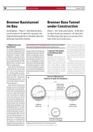
Phase III, the main construction<br />
phase of the <strong>Brenner</strong> <strong>Base</strong> <strong>Tunnel</strong><br />
(BBT), currently the European<br />
Union’s /EU’s) most important<br />
transport infrastructural project,<br />
was started on April 18, 2011 in<br />
Innsbruck – in the presence of<br />
the EU transport commissioner<br />
and coordinator as well as government<br />
representatives from<br />
Austria, Italy and Germany and<br />
the heads of the 2 rail systems<br />
involved from Austria and Italy.<br />
The construction costs are<br />
estimated at 7.45 b. euros (as<br />
of January 1, 2010) with 65 % of<br />
this total accounted for by the<br />
roughwork, 15 % for supporting,<br />
15 % for management and<br />
12.5 % for property rights as well<br />
as 7.5 % for risk provision. In addition<br />
1.144 b. euros must be added<br />
for an overall risk provision<br />
(ÖGG guideline). The construc-<br />
with the tunnels all being twinbore.<br />
Apart from the <strong>Brenner</strong><br />
and Pyrn motorways the Tauern<br />
represents one of the most<br />
important north-south links<br />
on the European transport<br />
network. The Autobahn- und<br />
Schnellstraßen-Finanzierungs<br />
AG (Asfinag) has invested<br />
around 3.7 m. euros in tunnel<br />
safety since the beginning of<br />
2001. By 2014 a further 1.1 m.<br />
euros is to be used to enhance<br />
tunnel safety (second tunnel<br />
bore, general renovation/redevelopment,<br />
expansion of the<br />
control centres etc.). G.B.<br />
tion programme for the 55 km<br />
long BBT between Innsbruck and<br />
Franzenfeste in Italy foresees the<br />
work being divided into 5 main<br />
contract sections:<br />
• 2 construction sections for<br />
exploratory tunnels and preparations<br />
for the construction<br />
phase as well as<br />
• 3 main contract sections (¼<br />
by conventional and ¾ by<br />
mechanised construction<br />
methods).<br />
The BBT is the key for the highspeed<br />
rail link between Berlin<br />
and Palermo (2,400 km) on<br />
the trans-European transport<br />
network (TEN) of the European<br />
Union (EU) and represents<br />
a decisive step en route to an<br />
effective and sustainable transport<br />
artery through the sensitive<br />
Alpine region. It is promoted by
<strong>Tunnel</strong> 7/2011<br />
schaft BBT SE vorangetrieben.<br />
Die österreichische Bundesbahn<br />
(ÖBB) hält in der weiteren<br />
Realisierungsphase 50 % und<br />
die italienische Bahngesellschaft<br />
(RFI) 42 % der Anteile; die<br />
restlichen 8 % teilen sich die 3<br />
Regionen Südtirol, Trient und<br />
Verona südlich des <strong>Brenner</strong>s.<br />
Deutschland<br />
Krammertunnel für Umfahrung von<br />
Garmisch-Partenkirchen<br />
Für den Bau des Krammertunnels<br />
(3,6 km) zur Umfahrung<br />
der Bundesstraße B 23 von Garmisch-Partenkirchen<br />
wurde am<br />
29. April 2011 der Erkundungsstollen<br />
(3.865 m) angeschlagen.<br />
Die Erkundungsergebnisse dienen<br />
der Bauvorbereitung für<br />
den einröhrigen Haupttunnel<br />
unter dem Krammergebirgsmassiv.<br />
Der Erkundungsstollen<br />
soll später als Flucht- und<br />
Deutschland<br />
NBS Ebensfeld-Erfurt:<br />
<strong>Tunnel</strong> Fleckberg<br />
Der zweigleisige und 1.490 m<br />
lange <strong>Tunnel</strong> Fleckberg zwischen<br />
den <strong>Tunnel</strong>n Silberberg (7.391 m)<br />
und Massenberg (1.051 m) ist<br />
Teil der 107 km langen Neubaustrecke<br />
(NBS) Ebensfeld-Leipzig<br />
mit insgesamt 22 <strong>Tunnel</strong>n mit<br />
zusammen 41 km Länge und<br />
38 % Streckenanteil, die 2017 in<br />
Betrieb gehen soll; sie gehört zur<br />
500 km langen Aus- und Neubaustrecke<br />
Nürnberg-Erfurt/Halle,<br />
dem Verkehrsprojekt Deutsche<br />
Einheit (VDE) Nr. 8.<br />
Der <strong>Tunnel</strong> Fleckberg ist<br />
einer der letzten in Angriff genommenen<br />
<strong>Tunnel</strong>bauwerken<br />
dieses Bauvorhabens. Er wird in<br />
Nachrichten News<br />
15<br />
Die Finanzierung wurde sowohl<br />
in Italien als auch in Österreich<br />
abgesichert, so dass weitere Erkundungsstollen<br />
gebaut und<br />
ab 2016 mit den Hauptbaulosen<br />
begonnen werden kann.<br />
Die Fertigstellung des BBT ist<br />
für 2025 geplant. G.B.<br />
Rettungsröhre für den Krammertunnel<br />
genutzt werden; bei<br />
einem Unfall oder einem Brand<br />
können sich Menschen über<br />
Fluchttüren in die parallel zum<br />
Haupttunnel verlaufende Röhre<br />
retten. Für die Baumaßnahmen<br />
zur künftigen Ortsumfahrung<br />
von Garmisch-Partenkirchen<br />
sind insgesamt 33 Mio. EUR<br />
vorgesehen. G.B.<br />
Teilausbrüchen (Kalotte, Strosse<br />
und Sohle) aufgefahren.<br />
Mit den Bauarbeiten wurde im<br />
Frühjahr 2011 begonnen; sie<br />
werden bis Herbst 2012 dauern.<br />
Die Investitionen für dieses<br />
<strong>Tunnel</strong>bauwerk werden etwa<br />
32 Mio. EUR betragen. G.B.<br />
the European project company<br />
BBT SE. The Austrian Federal<br />
Railway (ÖBB) will hold 50 % of<br />
the shares in the further phase<br />
of realisation and the Italian<br />
rail company (RFI) 42 %; the 3<br />
regions South Tyrol, Trient and<br />
Verona hold the remaining 8 %.<br />
Financing was secured both in<br />
Germany<br />
Krammer <strong>Tunnel</strong> for bypassing<br />
Garmisch-Partenkirchen<br />
Work started on the exploratory<br />
tunnel (3,685 m) for producing<br />
the Krammer <strong>Tunnel</strong> (3.6 km) to<br />
bypass the B 23 at Garmisch-<br />
Partenkirchen on April 29, 2011.<br />
The results of the exploration<br />
will serve to prepare for construction<br />
of the single-bore main<br />
tunnel beneath the Krammer<br />
massif. The exploratory tunnel<br />
will later be used as an evacuation<br />
and rescue tunnel for the<br />
Krammer <strong>Tunnel</strong>. In the event<br />
of an accident or a fire, people<br />
will be able to escape through<br />
doors into the gallery running<br />
parallel to the main tunnel. A<br />
total of 33 m. euros has been<br />
allocated for the scheme for<br />
bypassing Garmisch-Partenkirchen<br />
in future. G.B.<br />
Germany<br />
New Ebensfeld-Erfurt Rail Line:<br />
Fleckberg <strong>Tunnel</strong><br />
The twin-track and 1,490 m<br />
long Fleckberg <strong>Tunnel</strong> located<br />
between the Silberberg (7,391 m)<br />
and Messenger (1,051 m) tunnels<br />
is part of the 107 km long new<br />
rail link between Ebensfeld and<br />
Leipzig with a total of 22 tunnels<br />
altogether 41 km in length<br />
comprising 38 % of the route.It is<br />
Literatur / References<br />
[1] <strong>Tunnel</strong>bau für die NBS Ebensfeld-Erfurt. <strong>Tunnel</strong> 4/2008, pp. 20-21<br />
[2] NBS Ebensfeld-Erfurt: <strong>Tunnel</strong> Baumleite und Silberberg. <strong>Tunnel</strong><br />
7/2009, p. 4; Reitersbergtunnel.<br />
<strong>Tunnel</strong> 2/2010, p. 8<br />
[3] NBS Ebensfeld-Erfurt: <strong>Tunnel</strong> Eierberge. <strong>Tunnel</strong> 6/2010, p. 5; <strong>Tunnel</strong><br />
Lichtenholz. <strong>Tunnel</strong> 7/2010, p. 16<br />
[4] NBS Ebensfeld-Leipzig: Hauptvortrieb Silberbergtunnel.<br />
<strong>Tunnel</strong> 7/2010, p. 12; <strong>Tunnel</strong> Brandkopf, <strong>Tunnel</strong> 3/2011, pp. 14-15<br />
Italy as well as Austria so that<br />
further exploratory tunnels can<br />
be produced and work on the<br />
main contract sections started<br />
in 2016. The BBT is scheduled to<br />
be completed in 2025. G.B.<br />
scheduled to become operational<br />
in 2017 and belongs to the<br />
500 km long new and upgraded<br />
Nuremberg-Erfurt/Halle line, part<br />
of the German Unity Transport<br />
Project No. 8.<br />
The Fleckberg <strong>Tunnel</strong> is one<br />
of the last tunnel structures to<br />
be tackled for this scheme. It<br />
is being driven in part sections<br />
(crown, bench and floor). Work<br />
began in spring 2011 and is<br />
scheduled to last until autumn<br />
2012. The investments for this<br />
tunnel will amount to some<br />
32 m. euros. G.B.
16 Nachrichten<br />
News <strong>Tunnel</strong> 7/2011<br />
Österreich<br />
Semmering-Basistunnel:<br />
Bau genehmigt<br />
Der neue rund 27 km lange<br />
Semmering-Basistunnel darf<br />
jetzt gebaut werden, denn die<br />
oberste Eisenbahnbehörde Österreichs<br />
hat am 30. Mai nach<br />
genau einem Jahr Verfahren die<br />
Umweltverträglichkeit bestätigt<br />
und die Baugenehmigung erteilt.<br />
Die Naturschutz-Bescheide der<br />
Bundesländer Niederösterreich<br />
und Steiermark werden in Kürze<br />
erwartet.<br />
Der neue Semmering-Basistunnel<br />
erhält 2 eingleisige<br />
<strong>Tunnel</strong>röhren, die alle 500 m<br />
über Querschläge miteinander<br />
verbunden sind. Der <strong>Tunnel</strong> soll<br />
über die beiden Portale, Münzschlag<br />
im Westen und Gloggnitz<br />
im Osten, und 2 Zwischenangriffen<br />
aufgefahren werden,<br />
und zwar sowohl im zyklischen<br />
(Spritzbetonbauweise) als auch<br />
im kontinuierlichen (mit TVM)<br />
Vortrieb. Die Erkundungsphase<br />
für die Trassenführung wurde bereits<br />
Ende 2009 abgeschlossen.<br />
Die Bauarbeiten am Basistunnel<br />
sollen in der zweiten Hälfte 2012<br />
begonnen werden; mit der Inbetriebnahme<br />
des Semmering-Basistunnels<br />
wird 2024 gerechnet.<br />
Der Bau der gesamten neuen<br />
Südbahn umfasst den Neubau<br />
Wien Hauptbahnhof, den Ausbau<br />
der Pottendorf-Linie, den<br />
Bau des Semmering-Basistunnels,<br />
den Umbau des Bahnhofs<br />
Graz und die Koralm-Bahn und<br />
ist mit rund 10 Mrd. EUR veranschlagt,<br />
wovon 3 Mrd. EUR bereits<br />
auftragsmäßig vergeben<br />
oder verbaut sind. G.B.<br />
RWTH Aachen: Neuer Vertiefungsschwerpunkt<br />
<strong>Tunnel</strong>bau und Geotechnik im Masterstudiengang<br />
Bauingenieurwesen<br />
Mittlerweile ist auch im Bauingenieurwesen<br />
an der RWTH der<br />
bisherige Diplomstudiengang<br />
durch das konsekutive Bache-<br />
Univ.-Prof. Dr.-Ing. Martin Ziegler<br />
Prof. Martin Ziegler<br />
1<br />
Austria<br />
Semmering <strong>Base</strong> <strong>Tunnel</strong>:<br />
Construction approved<br />
The new roughly 27 km long Semmering<br />
<strong>Base</strong> <strong>Tunnel</strong> can now be<br />
built for Austria’s supreme railway<br />
authority confirmed its environmental<br />
compatibility on May 30,<br />
exactly a year after the relevant<br />
procedure was introduced, giving<br />
the green light for construction.<br />
Permits relating to nature conservation<br />
for the federal states<br />
of Lower Austria and Styria are<br />
expected shortly.<br />
The new Semmering <strong>Base</strong><br />
<strong>Tunnel</strong> will possess 2 single-track<br />
bores, which are connected every<br />
500 m by cross-passages. The<br />
tunnel is to be driven via the 2<br />
portals, Münzschlag in the west<br />
and Gloggnitz in the east – and<br />
Literatur / References<br />
[1] Planung für Semmering-Basistunnel. <strong>Tunnel</strong> 3/2006, p. 2<br />
[2] Koralm- und Semmering-Basistunnel, Südbahntagung.<br />
<strong>Tunnel</strong> 5/2009, pp. 50-54<br />
[3] Neuer Semmering-Basistunnel: Erkundungsphase abgeschlossen.<br />
<strong>Tunnel</strong> 3/2010, p. 12<br />
lor-/Masterstudium ersetzt<br />
worden. Das Masterstudium<br />
konnte erstmals zum Wintersemester<br />
2010/2011 aufge-<br />
2 intermediate points of attack<br />
– both in cycles (shotcreting) as<br />
well as continuous excavation<br />
(TBM). The exploratory phase for<br />
the route alignment was completed<br />
at the end of 2009. Construction<br />
work on the <strong>Base</strong> <strong>Tunnel</strong> is<br />
due to start in the second half of<br />
2012; the Semmering <strong>Base</strong> <strong>Tunnel</strong><br />
is scheduled for be commissioned<br />
in 2024.<br />
Construction of the entire<br />
Südbahn comprises the rebuilding<br />
of Vienna’s Main Station,<br />
upgrading the Pottendorf route,<br />
producing the Semmering <strong>Base</strong><br />
<strong>Tunnel</strong>, redeveloping Graz Station<br />
and the Koralm-Bahn. It is due to<br />
cost some 10 b. euros, 3 b. euros<br />
of which has been either contractually<br />
allocated or spent. G.B.<br />
RWTH Aachen: new special focuses<br />
<strong>Tunnel</strong>ling and Geotechnics as<br />
Master Courses in Civil Engineering<br />
The former diploma course at<br />
the RWTH in civil engineering<br />
has now also been replaced by<br />
the consecutive Bachelor/Master<br />
course of studies. The Master<br />
course was first introduced for<br />
the winter semester 2010/2011.<br />
In this connection the 4 previous<br />
special focuses were expanded<br />
to 8. The new special<br />
focuses include tunnelling and<br />
geotechnics provided by the<br />
Chair of Geotechnics headed<br />
by Prof. Martin Ziegler (Fig. 1).<br />
The Master study course is<br />
set up as a 3-tier system (Ta-<br />
ble). Tier 1 concentrates on<br />
special focuses from the field<br />
of geotechnics and tunnelling.<br />
In tier 1 there are only very limited<br />
opportunities to select<br />
subjects from other special focuses.<br />
However this is certainly<br />
possible in tiers 2 and 3. In tier<br />
2 apart from special lectures relating<br />
to Geotechnics the possibility<br />
is offered to choose essential<br />
special focuses from the<br />
sectors constructional engineering,<br />
waterways engineering,<br />
construction management or<br />
transport planning depending
<strong>Tunnel</strong> 7/2011<br />
nommen werden. Damit verbunden<br />
war eine Ausweitung<br />
der bisherigen 4 Vertiefungsrichtungen<br />
auf insgesamt 8<br />
Vertiefungsschwerpunkte. Neu<br />
hinzugekommen ist u.a. der<br />
Vertiefungsschwerpunkt <strong>Tunnel</strong>bau<br />
und Geotechnik, der<br />
federführend vom Lehrstuhl<br />
für Geotechnik im Bauwesen<br />
unter der Leitung von Univ.-<br />
Prof. Dr.-Ing. Martin Ziegler<br />
angeboten wird (Bild 1).<br />
Das Masterstudium ist als<br />
Dreischalenmodell aufgebaut<br />
(Tabelle). In der ersten Schale<br />
werden schwerpunktmäßig<br />
Vertiefungsfächer aus dem<br />
Bereich der Geotechnik und<br />
des <strong>Tunnel</strong>baus angeboten.<br />
In dieser ersten Schale gibt es<br />
nur sehr eingeschränkte Möglichkeiten,<br />
Fächer aus anderen<br />
Vertiefungsschwerpunkten<br />
zu wählen. Dies ist aber ohne<br />
weiteres in der zweiten und<br />
dritten Schale möglich. In der<br />
zweiten Schale wird neben<br />
einigen Spezialvorlesungen<br />
aus dem Bereich Geotechnik<br />
die Möglichkeit geboten, je<br />
nach zukünftig gewünschtem<br />
Profil die wesentlichen Vertiefungsfächer<br />
aus den Bereichen<br />
Konstruktiver Ingenieurbau,<br />
Wasserbau, Baubetrieb oder<br />
Verkehrsplanung zu wählen.<br />
In der dritten Schale bestehen<br />
hinsichtlich der Fächerwahl fast<br />
keine Einschränkungen. Durch<br />
das Schalenmodell wird dem<br />
Studierenden die Möglichkeit<br />
geboten, eine Spezialisierung<br />
in den Fächern <strong>Tunnel</strong>bau und<br />
Geotechnik zu erhalten, ohne<br />
auf eine Vertiefung in einem<br />
weiteren Vertiefungsschwerpunkt<br />
verzichten zu müssen.<br />
Damit lässt der in der Praxis<br />
erhobene Wunsch nach einer<br />
möglichst breiten Ingenieursausbildung,<br />
die das Kennzeichen<br />
des früheren Diplomin-<br />
Nachrichten News<br />
17<br />
genieurs an der RWTH Aachen<br />
war, auch mit dem neuen Bachelor-/Masterstudiengang<br />
mit Vertiefungsschwerpunkt<br />
<strong>Tunnel</strong>bau und Geotechnik<br />
realisieren.<br />
Kernfächer des neuen Vertiefungsschwerpunkts<br />
sind<br />
neben den bisher schon angebotenen<br />
Vertiefungsfächern<br />
in Grundbau, Boden- und Felsmechanik<br />
die neuen Lehrveranstaltungen<br />
Bau und Berechnung<br />
von <strong>Tunnel</strong>n, sowie eine<br />
erweiterte Projektstudie aus<br />
dem Bereich des <strong>Tunnel</strong>baus.<br />
In die Lehrveranstaltung Bau<br />
und Berechnung von <strong>Tunnel</strong>n<br />
ist eine eigene Vorlesung über<br />
Sprengtechnik sowie eine<br />
weitere über die Organisation<br />
von großen <strong>Tunnel</strong>projekten<br />
integriert. Wir freuen uns, dass<br />
wir für beide Veranstaltungen<br />
erfahrene und namhafte Lehrbeauftragte<br />
aus der Praxis gewinnen<br />
konnten. So wird die<br />
Sprengtechnik von Dr.-Ing.<br />
Peter Reinders von Orica Mining<br />
Services gehalten und<br />
die Organisation von großen<br />
<strong>Tunnel</strong>projekten von dem<br />
früheren Vorsitzenden der Geschäftsleitung<br />
der AlpTransit<br />
Gotthard AG Dipl.-Ing. Peter<br />
Zbinden. Diese beiden Vorlesungen<br />
werden erstmals zum<br />
Wintersemester 2011/2012<br />
angeboten.<br />
In der bereits im Sommersemester<br />
2011 durchgeführten<br />
Projektstudie wurden Teilaspekte<br />
der Wehrhahnlinie in<br />
Düsseldorf von Studierenden<br />
im Team bearbeitet. Ziel war<br />
dabei, aus freundlicherweise<br />
vom Amt für Verkehrsmanagement<br />
der Stadt Düsseldorf und<br />
der Projektleitung der Wehrhahnlinie<br />
zur Verfügung gestellten<br />
Unterlagen sich z.B. ein<br />
Baugrundmodell zu erarbeiten,<br />
maßgebende Berechnungs-<br />
on future requirements. In tier<br />
3 there are practically no limitations<br />
regarding the choice of<br />
subjects. Thanks to this 3-tier<br />
set-up the student is provided<br />
with the possibility of specialising<br />
in tunnelling and geotechnics<br />
without having to renounce<br />
specialisation in a further special<br />
focus. Consequently the desire<br />
expressed in practice for training<br />
as widely structured as<br />
possible in engineering, which<br />
was characterised by the former<br />
diploma in engineering at the<br />
RWTH Aachen, can be fulfilled<br />
with the new Bachelor/Master<br />
course with special focus on<br />
tunnelling and geotechnics.<br />
Core subjects of the new<br />
special focus in addition to those<br />
provided so far in foundation<br />
engineering, soil and rock mechanics<br />
are new courses in building<br />
and dimensioning tunnels<br />
as well as an extended project<br />
study from the tunnelling sector.<br />
The course devoted to building<br />
and dimensioning tunnels<br />
also includes lectures devoted<br />
to drill+blast as well as others<br />
on organisation of major tunnel<br />
projects. We are delighted that<br />
we have been able to gain the<br />
services of experienced leading<br />
experts from practice for the 2<br />
classes. Dr.-Ing. Peter Renders of<br />
Orica Mining Services will present<br />
the course on drill+blast<br />
whilst the topic of organising<br />
major tunnel projects will be<br />
taken charge of by the former<br />
CEO of the AlpTransit Gotthard<br />
AG Dipl.-Ing. Peter Zbinden.
18 Nachrichten<br />
News <strong>Tunnel</strong> 7/2011<br />
Modul Nr. Lehrveranstaltungen<br />
Summen<br />
SWS CP<br />
T 1 Grundbau Vertiefung 3 5 Geotechnik<br />
T 2 Grundlagen Felsmechanik und Felsbau 2 3 Geotechnik<br />
T 3 Bodenmechanik Vertiefung 3 6 Geotechnik<br />
T 4 Geokunststoffe 2 2 Geotechnik<br />
T 5<br />
T 6<br />
Bau und Berechnung von <strong>Tunnel</strong>n 4<br />
Sprengtechnik 0,5<br />
Organisation von <strong>Tunnel</strong>bauprojekten 0,5<br />
Lehrstuhl Wahlmöglichkeiten<br />
8 Geotechnik<br />
Bauvertragsmanagement 2 3 Baubetrieb / Projektmanagement<br />
Projektmanagement Master 3 5<br />
T 7<br />
<strong>Tunnel</strong>planung<br />
<strong>Tunnel</strong>betrieb<br />
2<br />
3<br />
8 Straßenwesen<br />
T 8 Numerische Methoden 2 4 Angewandte Mechanik<br />
T 9 Plastizitätstheorie und Bruchmechanik 3 6 Angewandte Mechanik<br />
T 10 Geotechnische Mess- und Versuchstechnik 2 3 Geotechnik<br />
T 11 Geotechnische Projektstudie 3 5 Geotechnik<br />
T 12<br />
Felsbau<br />
Staudammbau<br />
2<br />
1<br />
5 Geotechnik<br />
T 13 Ingenieurgeologische Erkundungsverfahren 2 3 Ingenieurgeologie<br />
T 14 Bautechnik von Verkehrsanlagen II 5 8 Straßenwesen<br />
T 15<br />
Wasserbau III 2 4<br />
Küsteningenieurwesen 2 4<br />
Wasserbau<br />
T 16<br />
Massivbau III-a (Ausgewählte Kapitel des Massivbaus)<br />
Massivbau III-b (Spannbetonbau)<br />
3<br />
2<br />
8 Massivbau<br />
T 17 Beton - Eigenschaften und Prüfung Teil I und Teil II 5 8 Baustoffkunde<br />
T 18 Kontinuumsmechanik 5 8 Angewandte Mechanik<br />
T 19 Finanzierung von Verkehrsinfrastruktur und Betrieb 6 8<br />
Straßenwesen / Stadtbauwesen /<br />
Schienenbahnwesen<br />
T 20 Hydromechanik III 2 4 Wasserbau<br />
T 21 Hochwasserschutz 2 3 Wasserbau<br />
T 22<br />
Verkehrswasserbau I<br />
Verkehrswasserbau II<br />
2<br />
2<br />
3<br />
3<br />
Wasserbau<br />
T 23 Wasserbauliches Versuchswesen 2 3 Wasserbau<br />
T 24 Grundwasserbewirtschaftung 2 3 Wasserbau<br />
T 25<br />
Sickerwasserprognose<br />
Verwertung mineralischer Feststoffe<br />
2<br />
2<br />
6 Abfallwirtschaft<br />
T 26 Massivbau IV 5 8 Massivbau<br />
T 27 Bauwerkserhaltung 1 BM 3 4 Baustoffkunde<br />
T 28 Zusatzmittel für Beton 2 3 Baustoffkunde<br />
T 29 Abstimmung der Wahl mit Prüfungsausschuss / Fachstudienberatung 5 8<br />
T 30 Abstimmung der Wahl mit Prüfungsausschuss / Fachstudienberatung 5 8<br />
Gesamt-CPs zu wählen 96CP<br />
Master-Arbeit 24 CP<br />
(Master-Arbeit ) (24 CP)<br />
Summe 120 CP<br />
Dreischalenmodell des Masterstudienganges an der RWTH Aachen<br />
Three-tier model for Master courses at the RWTH Aachen<br />
Schale 1:<br />
40 CP aus T 1 - T 9<br />
Schale 2:<br />
32 CP aus T 10 - T 18<br />
und nicht gewählten T 1 bis T 9<br />
Schale 3:<br />
24 CP aus T 19 - T 30<br />
und nicht gewählten T 10 - T 18
<strong>Tunnel</strong> 7/2011<br />
schnitte zu identifizieren oder<br />
Bauabläufe festzulegen. Das<br />
Konzept dieser Lehrveranstaltung<br />
stieß auf große Zustimmung<br />
bei den Studierenden,<br />
so dass wir uns entschlossen,<br />
dieses zu einem „Reality Learning“<br />
zu erweitern, indem z.B.<br />
in videoaufgezeichneten fiktiven<br />
Baubesprechungen mit<br />
verteilten Rollen die eigenen<br />
Ausarbeitungen in größerer<br />
Runde vorgestellt und auch<br />
verteidigt werden müssen. Für<br />
��������������<br />
Nachrichten News<br />
19<br />
das erweiterte Konzept wurde<br />
bei der RWTH Aachen im Rahmen<br />
der Exzellenz der Lehre<br />
für das Programm Exploratory<br />
Teaching Space, eine Plattform<br />
für kreative Ideengenerierung<br />
künftiger Lehr- und Lernformen<br />
an der RWTH Aachen,<br />
eine Förderung beantragt, die<br />
im August dieses Jahres positiv<br />
beschieden wurde. Wir freuen<br />
uns, das neue Konzept damit<br />
kurzfristig umsetzen zu können.<br />
Weitere Informationen zum neuen Masterschwerpunkt auf<br />
www.geotechnik.rwth-aachen.de unter Lehre/Studiengänge.<br />
Prof. Martin Ziegler<br />
��������������������������������������������<br />
�����������������������������������<br />
Fire safety engineering with tailored solutions and<br />
convincing customer support.<br />
����������������������������������������������������<br />
��������������������������������������������������������<br />
��������������������������������������������������������<br />
��������������<br />
������������ �������������������������������������������<br />
������������������������������������������������������<br />
� �����������������������������������������������<br />
�������������<br />
� �������������������������������<br />
� ������������������������������������������������������<br />
��������������������<br />
These 2 classes will be introduced<br />
for the 2011/2012 winter<br />
semester.<br />
In the project study introduced<br />
during the 2011 summer<br />
semester partial aspects of the<br />
Wehrhahnlinie in Düsseldorf<br />
were tackled by teams of students.<br />
Towards this end the aim<br />
was, on the basis of documents<br />
kindly made available by the<br />
City of Düsseldorf’s Office for<br />
Transport Management and<br />
the Wehrhahnlinie’s project<br />
management, to work out a<br />
subsoil model, identify decisive<br />
analysis sections or determine<br />
construction cycles. The concept<br />
of this course met with<br />
great resonance among the<br />
���������������������������������������������<br />
�������������������������������������������������������<br />
���������������������������������������������<br />
������������ �����������������������������������<br />
������������������������������������������������<br />
�������������������������<br />
� ������������������������������������������������<br />
��������������������������������<br />
� ��������������������������<br />
� �������������������������������������������<br />
����������<br />
students therefore we decided<br />
to expand this in the form of<br />
“reality learning” so that e.g. in<br />
video-recorded fictitious consultations<br />
– with corresponding<br />
roles being adopted, the various<br />
proposals were presented and<br />
also defended within a greater<br />
group. For this expanded concept<br />
a platform for creative idea<br />
generation for future forms of<br />
teaching and learning sponsorship<br />
was applied for from<br />
the RWTH within the scope of<br />
the Exploratory Teaching Space<br />
programme. This was granted<br />
in August this year. We are really<br />
pleased to be in a position<br />
to apply the new concept so<br />
quickly.<br />
Fermacell GmbH<br />
������������������<br />
���������������������������������<br />
�����������������������������<br />
�������� ��������������������<br />
������� ����������������<br />
���������������
20 Stahlfaserspritzbeton - Stand der Technik <strong>Tunnel</strong> 7/2011<br />
Stahlfaserspritzbeton<br />
im <strong>Tunnel</strong>bau:<br />
Stand der Technik und<br />
Beispiele<br />
Die Möglichkeiten und Gründe für den Einsatz<br />
von Stahlfaserbeton im <strong>Tunnel</strong>bau sind vielfältig,<br />
woraus die Vielzahl existierender Anwendungsvarianten<br />
resultiert. Die Spritzbetonbauweise<br />
ist bereits seit Jahren Stand der Technik<br />
und der folgende Beitrag gibt einen Überblick.<br />
1 Einführung<br />
Die Bereitschaft für den Einsatz<br />
von Stahlfaserspritzbeton im<br />
<strong>Tunnel</strong>bau steigt mit der Anforderung<br />
an Sicherheit, verfahrenstechnischer<br />
Vereinfachung<br />
und Bauzeitverkürzung, den<br />
die Verwendung des Baustoffes<br />
ermöglicht sowie den Kosten,<br />
die gegenüber einer herkömmlichen<br />
Konstruktionslösung aus<br />
Stahlbeton eingespart werden.<br />
Im Spritzbetonverfahren bietet<br />
der Stahlfaserbeton den Vorteil,<br />
dass der ausgesprochen komplizierte<br />
sowie zeitaufwändige<br />
Einbau der Bewehrung entfällt<br />
(Bild 1).<br />
Nicht nur der Bauablauf wird<br />
beschleunigt, zudem wird auch<br />
die frühzeitige Aktivierung der<br />
Erstsicherung des Gebirges sichergestellt.<br />
Unter schwierigen<br />
geologischen Bedingungen<br />
treten zwischen dem Auffahren<br />
des Querschnitts und der<br />
Aktivierung der Sicherung, Auflockerungen<br />
im Gebirge auf.<br />
Bei schlechten Gebirgsverhältnissen<br />
erweist sich eine frühzeitige<br />
Tragwirkung der Sicherung<br />
als zielführend. Die frühe<br />
Tragfähigkeit wird durch das<br />
zügige Einbauverfahren und<br />
Dipl.-Ing. Philipp Guirguis, Bekaert GmbH,<br />
Technical Manager for Construction Products, Friedrichsdorf / D,<br />
www.bekaert.de<br />
die hohe Frühfestigkeit des<br />
Stahlfaserspritzbetons erzielt.<br />
Die Zugabe der Stahlfasern im<br />
Spritzbetonverfahren erfolgt in<br />
der Regel über Dosiereinrichtungen<br />
direkt in das Bereitstellungsgemisch<br />
im Betonwerk.<br />
Beim Stahlfaserspritzbeton ist<br />
der Rückprall, der zu einem<br />
geringeren Fasergehalt in der<br />
<strong>Tunnel</strong>schale im Vergleich<br />
zum Bereitstellungsgemisch<br />
führt, zu beachten. Aufgrund<br />
des Auffahrprozesses ist eine<br />
Orientierung der Fasern senkrecht<br />
zur Auftragsrichtung zu<br />
beobachten, was aus Sicht<br />
der Trageigenschaften als positiver<br />
Effekt zu bewerten ist.<br />
Beide zuvor genannten Effekte<br />
führen beim Stahlfaserspritzbeton<br />
dazu, dass Prüfkörper<br />
zur Ermittlung des Energieabsorptionsvermögens,<br />
unter<br />
gleichen Bedingungen zum<br />
späteren Bauwerk hergestellt<br />
und ausgewertet werden.<br />
Je länger und dünner die<br />
Stahlfasern, desto positiver<br />
ist der Einfluss auf Duktilität,<br />
Tragfähigkeit und Energieab-<br />
Steel Fibre Shotcrete in<br />
<strong>Tunnel</strong>ling:<br />
State of the Art and Examples<br />
There are many possibilities and reasons for the<br />
application of steel fibre concrete in tunnelling,<br />
which account for the manifold number of existing<br />
uses. The shotcreting construction method<br />
has been state of the art for many years, which<br />
is reflected in the following report.<br />
1 Introduction<br />
The readiness to apply steel fibre<br />
shotcrete in tunnelling increases<br />
with demands on safety, processtechnological<br />
streamlining and<br />
reducing the construction time,<br />
which facilitates the use of the<br />
material as well as costs, which<br />
are saved compared with a conventional<br />
reinforced concrete<br />
structural solution. With regard<br />
to the shotcreting method steel<br />
fibre concrete offers the advantage<br />
that there is no need for<br />
the extremely complicated and<br />
time-consuming installation of<br />
reinforcement (Fig. 1).<br />
The construction process is<br />
speeded up. Furthermore the<br />
initial securing of the rock sets<br />
in at an early stage. Loosening of<br />
the rock occurs between driving<br />
the cross-section and activating<br />
the support given tricky geological<br />
conditions. In the case of<br />
poor rock conditions early activation<br />
of the bearing effect of<br />
the support helps achieve the<br />
target. This early bearing behaviour<br />
is attained by the speedy<br />
installation method and the early<br />
setting strength. The addition of<br />
the steel fibres in the shotcreting<br />
process generally takes place via<br />
dosing units for the ready mix in<br />
the concrete plant. In the case of<br />
steel fibre shotcrete the rebound,<br />
which leads to a slight fibre content<br />
in the tunnel shell compared<br />
with the ready mix, must be taken<br />
into consideration. Owing to<br />
the driving process orientation<br />
of the fibres perpendicular to the<br />
direction of placement is to be<br />
observed, something which can<br />
be assessed as positive regarding<br />
the bearing characteristics. In the<br />
case of steel fibre shotcrete the<br />
2 previously mentioned effects<br />
lead to test specimens being<br />
produced and evaluated to establish<br />
the energy absorption<br />
capacity under the same conditions<br />
prevailing at the subsequent<br />
structure. The longer and<br />
thinner the steel fibres are the<br />
more positive their influence on<br />
the ductility, bearing capacity<br />
and energy absorption capacity<br />
of the steel fibre shotcrete is.<br />
However the fibre length should<br />
be restricted to some 35 mm on<br />
account of processibility and<br />
should not exceed 2/3 rd of the<br />
hose diameter.
<strong>Tunnel</strong> 7/2011<br />
1<br />
Typisches Einbauverfahren von Mattenbewehrung im <strong>Tunnel</strong>bau<br />
Typical installation method for mat reinforcement in tunnelling<br />
sorptionsvermögen des Stahlfaserbetons.<br />
Allerdings ist aufgrund<br />
der Verarbeitbarkeit die<br />
Faserlänge auf ca. 35 mm zu<br />
begrenzen und sollte 2/3 des<br />
Schlauchdurchmessers nicht<br />
überschreiten.<br />
2 Materialeigenschaften<br />
des Stahlfaserbetons<br />
Stahldrahtfasern werden dem<br />
Beton zugemischt, um neben<br />
einer Traglasterhöhung, verschiedene<br />
mechanische Eigenschaften<br />
des Betons zu verbessern.<br />
Zu den maßgebenden<br />
Eigenschaften, die durch die<br />
Zugabe von Stahldrahtfasern<br />
deutlich verbessert werden,<br />
zählen:<br />
• Duktilitätssteigerung unter<br />
Zug und Druck<br />
• erhöhte Schlagfestigkeit<br />
• verbessertes Ermüdungsverhalten<br />
• geringere Abplatzneigung<br />
• erhöhte Dauerhaftigkeit<br />
• geringere Rissbreiten im Gebrauchszustand<br />
• Biegetragfähigkeit in allen 3<br />
Raumrichtungen<br />
Steel Fibre Shotcrete - State of the Art<br />
Der Einsatz von Stahlfaserbeton<br />
bietet im Vergleich zum Einsatz<br />
herkömmlicher Betonstahlbewehrung<br />
beim Spritzbetonverfahren<br />
im <strong>Tunnel</strong>bau deutliche<br />
Vorzüge. Hierzu zählen insbesondere<br />
erhöhte Arbeitssicherheit,<br />
Kosteneinsparungen bei<br />
den Bewehrungsarbeiten sowie<br />
Vereinfachung und Beschleunigung<br />
des gesamten Bauablaufs.<br />
Es ergibt sich eine bessere Homogenität<br />
der Spritzschicht, da<br />
keine Spritzschatten aufgrund<br />
Spritzen durch eine Bewehrung<br />
auftreten. Hinzu kommt, dass<br />
weniger Überprofil ausgespritzt<br />
werden muss, da den<br />
Konturen des Gebirges besser<br />
gefolgt werden kann.<br />
3 Normierung von<br />
Stahlfasern in der EN<br />
14889-1<br />
In Europa sind Stahlfasern zur<br />
Verwendung in Beton mit dem<br />
CE-Zeichen zu kennzeichnen.<br />
Die Mindestanforderungen an<br />
Stahlfasern werden in der harmonisierten<br />
Norm EN 14889-<br />
1 [6] beschrieben. Die Norm<br />
2 Material Properties of<br />
Steel Fibre Shotcrete<br />
Steel wire fi bres are mixed with<br />
concrete, in order to improve various<br />
mechanical properties of<br />
the concrete quite apart from<br />
enhancing the bearing eff ect.<br />
The decisive characteristics,<br />
which are considerably improved<br />
through the addition of steel<br />
wire fi bres, include:<br />
• increased ductility given tension<br />
and pressure<br />
• enhanced impact strength<br />
• improved fatigue behaviour<br />
• low propensity for spalling<br />
• increased durability<br />
• slighter crack widths in operational<br />
state<br />
• bending tensile capacity in all<br />
3 spatial directions<br />
Innovativer – Kompetenter – Zuverlässiger<br />
Gemeinsam stärker<br />
im <strong>Tunnel</strong>bau<br />
Schläuche · Armaturen · Zubehör für:<br />
hoses · fittings · equipment for:<br />
Pressluft compressed air<br />
Wasser water<br />
Beton concrete<br />
TechnoBochum<br />
Salweidenbecke 21<br />
44894 Bochum, Germany<br />
Tel. +49 (0)2 34/5 88 73-73<br />
Fax +49 (0)2 34/5 88 73-10<br />
info@techno-bochum.de<br />
www.techno-bochum.de<br />
21
22 Stahlfaserspritzbeton - Stand der Technik <strong>Tunnel</strong> 7/2011<br />
legt Anforderungen für Stahlfasern<br />
für Beton, Mörtel und<br />
Einpressmörtel für tragende<br />
und andere Zwecke fest. Es<br />
gibt 2 unterschiedliche Systeme<br />
der Konformitätsbescheinigung:<br />
• System 1 – Stahlfasern für<br />
tragende Zwecke und<br />
• System 3 – Stahlfasern für<br />
andere Zwecke.<br />
Die Norm definiert tragende<br />
Zwecke wie folgt: “Bei der<br />
Verwendung von Fasern für<br />
tragende Zwecke tragen die<br />
zugegebenen Fasern zur Tragfähigkeit<br />
eines Betonbauteils<br />
bei.“ Demnach ist für fast alle<br />
praktisch relevanten Fälle eine<br />
Konformitätsbescheinigung<br />
nach System „1“ erforderlich<br />
Um Verwechslungen vorzubeugen,<br />
sollten ausschließlich<br />
nach System „1“ überwachte<br />
und zertifizierte Stahlfasern mit<br />
zugehörigem EG-Konformitätszertifikat<br />
verwendet werden.<br />
In der Norm sind für die jeweils<br />
maßgebenden Eigenschaften<br />
der Fasern zulässige Toleranzen<br />
festgelegt. Um Unterschiede in<br />
der Leistungsfähigkeit einzelner<br />
Fasertypen transparent darzulegen,<br />
wird an einem Referenzbeton<br />
der Einfluss auf die Festigkeit<br />
von Beton getestet. Es ist die Mindestzugabemenge<br />
Stahlfasern<br />
definiert, die erforderlich ist, um<br />
in einem Prüfverfahren nach DIN<br />
EN 14651 [5] eine residuelle Biegezugfestigkeit<br />
von 1,5 N/mm2<br />
bei einer Rissöffnungsbreite von<br />
0,5 mm und von 1,0 N/mm2 bei<br />
einer Rissöffnungsbreite von 3,5<br />
mm zu erreichen.<br />
4 Europäische Norm für<br />
Spritzbeton in der EN<br />
14487-1<br />
In der europäischen Norm für<br />
Spritzbeton EN 14887-1 [2] wird<br />
die Verwendung von Fasern ge-<br />
regelt und erforderliche Testverfahren<br />
zur Ermittlung von<br />
Duktilität und Leistungsfähigkeit<br />
verschiedener Faserbetone<br />
beschrieben. Zwei unterschiedliche<br />
Testverfahren sind in dieser<br />
Norm aufgenommen:<br />
Statisch unbestimmte Plattenprüfungen<br />
zur Ermittlung<br />
des Energieabsorptionsvermögen<br />
(Systemtragfähigkeit) nach<br />
EN 14488-5 [4] und statisch<br />
bestimmte Balkenprüfungen<br />
zur Ermittlung der Querschnittstragfähigkeit<br />
nach EN<br />
14488-3 [3]. Die EN 144887- 1<br />
[2] verweist somit bezüglich<br />
der Testverfahren auf weitere<br />
europäische Normen, die im<br />
anschließenden Kapitel aufgegriffen<br />
und erläutert werden.<br />
Die Klassifizierung von<br />
Festigkeitsklassen und zugeordneter<br />
Durchbiegung nach<br />
EN 14488-3 [3] erfolgt gemäß<br />
Tabelle 1. Es ist wichtig zu beachten,<br />
dass der gewählte Festigkeitswert<br />
(S1-S4) auf keinem<br />
Punkt der Last-Verformungskurve<br />
im entsprechenden<br />
Verformungsbereich (D1 –D3)<br />
unterschritten wird.<br />
Compared to applying conventional<br />
reinforced concrete<br />
the application of steel fibre<br />
concrete affords clear advantages<br />
in conjunction with<br />
the shotcreting method in<br />
tunnelling. In particular these<br />
relate to increased industrial<br />
safety, cost saving for the reinforcing<br />
operations as well as<br />
making the entire work cycle<br />
more straightforward and<br />
quicker. The sprayed layer is<br />
more homogeneous as no<br />
spraying shadows occur on<br />
account of spraying through<br />
reinforcement. In addition<br />
there is the fact that less<br />
overbreak has to be sprayed<br />
as the rock contours can be<br />
followed better.<br />
3 Standardising Steel<br />
Fibres in the EN 14889-1<br />
In Europe steel fibres for application<br />
in concrete have to be<br />
accorded the CE marking. The<br />
minimum requirements for<br />
steel fibres are described in the<br />
standardised norm EN 14889-1<br />
[6]. The norm establishes requirements<br />
for concrete, mortar and<br />
Verformungsbereich Festigkeitsklasse (Mindestwert) in [MPa]<br />
Verformung<br />
[mm]<br />
S1 S2 S3 S4<br />
D1 0,5 bis 1<br />
D2 0,5 bis 2 1 2 3 4<br />
D3 0,5 bis 4<br />
Tabelle 1: Definition der residuellen Festigkeitsklassen<br />
Deformation area Strength class (min. value) in [MPa]<br />
Deformation<br />
[mm]<br />
S1 S2 S3 S4<br />
D1 0,5 to 1<br />
D2 0,5 to 2<br />
1 2 3 4<br />
D3 0,5 to 4<br />
Table 1: Definition of the residual Strength Classes<br />
Für das Energieabsorptionsvermögen<br />
definiert die EN 14488-5<br />
[4] die in Tabelle 2 aufgeführten<br />
Klassen.<br />
grouting mortar for bearing and<br />
other purposes. There are 2 different<br />
systems for certificating the<br />
conformity:<br />
• System 1 – steel fibres for bearing<br />
purposes and<br />
• System 3 – steel fibres for<br />
other purposes.<br />
The norm defines bearing purposes<br />
as follows: “when applying<br />
fibres for bearing purposes the<br />
added fibres contribute towards<br />
the bearing capacity of a concrete<br />
element”. Accordingly a System<br />
“1” certification of the conformity<br />
is necessary for practically all<br />
relevant cases. Thus only steel fibres<br />
monitored and certificated<br />
in accordance with System “1”<br />
with the relevant EU certificate<br />
of conformity should be applied<br />
in order to avoid any confusion.<br />
The norm contains the permissible<br />
tolerances for the properties of<br />
the fibres applicable in each case.<br />
In order to present differences in<br />
the capabilities of the individual<br />
types of fibres in a clear manner<br />
the influence on the concrete’s<br />
strength is tested on a reference<br />
concrete. The minimum amount<br />
of added steel fibre is defined,<br />
which is necessary to attain a residual<br />
bending tensile strength<br />
of 1.5 N/mm2 given a crack opening<br />
width of 0.5 mm and of 1.0<br />
N/mm2 given a crack opening<br />
width of 3.5 mm in a test procedure<br />
in accordance with DIN EN<br />
14651 [5].<br />
4 European Norm for<br />
Shotcrete in the EN<br />
14487-1<br />
The European norm for shotcrete<br />
EN 14887-1 [2] defines the application<br />
of fibres and describes<br />
necessary test methods to determine<br />
the ductility and capabilities<br />
of various fibre concretes.<br />
Two different test methods are<br />
included in this norm: statically<br />
undefined slab tests to determine<br />
the energy absorption capacity<br />
(system bearing capacity)<br />
according to EN 14488-5 [4] and
<strong>Tunnel</strong> 7/2011<br />
Erlaubt das Ergebnis statisch unbestimmter<br />
Plattenprüfungen eine Aussage über<br />
die Systemtragfähigkeit (sinnvollerweise<br />
heranzuziehen bei typisch rückverankerten<br />
Spritzbetonschalen), lässt das<br />
Ergebnis von Balkenprüfungen eine Aussage<br />
über die Querschnittstragfähigkeit<br />
zu (sinnvollerweise zu verwenden in einer<br />
Bemessung, in der die Querschnittstragfähigkeit<br />
als Materialwiderstand herangezogen<br />
wird).<br />
Insofern unterscheiden sich nicht<br />
nur die Testverfahren sondern auch die<br />
Ergebnisse derselben. Folglich können<br />
Ergebnisse von Plattenprüfungen nicht<br />
für Bemessungen herangezogen werden,<br />
in denen auf der Widerstandsseite<br />
die Querschnittstragfähigkeit angesetzt<br />
wird (üblicher Vorgang bei Tragwerksbemessungen).<br />
5 Testverfahren zur Ermittlung<br />
der Leistungsfähigkeit<br />
5.1 Plattenprüfungen nach EN 14488-5<br />
Bestimmung der Energieabsorption bei<br />
faserverstärkten plattenförmigen Prüfkörpern:<br />
Das verformungsgesteuerte Testverfahren<br />
betrachtet einen quadratischen<br />
Prüfkörper mit der Abmessung 600 x 600<br />
mm und einer Plattendicke von 100 mm<br />
(siehe auch Bild 12). Dieser wird unter<br />
Baustellenbedingungen gefertigt um<br />
die Effekte Faserorientierung und Faserrückprall<br />
zu berücksichtigen (Bild 2). Der<br />
Prüfkörper wird für den Test ringsum frei<br />
drehend gelagert und über eine Einzellast<br />
in Plattenmitte verformungsgesteuert bis<br />
auf eine maximale Durchbiegung von 30<br />
mm belastet (Auswertung erfolgt bei 25<br />
Steel Fibre Shotcrete - State of the Art<br />
Energieabsorptionsklasse Absorbierte Energie im Joule bei einer Durchbiegung bis maximal 25 mm<br />
E500 500<br />
E700 700<br />
E1000 1000<br />
Tabelle 2: Definition der Energieabsorptionsklasse<br />
Energy absorption class Absorbed energy in joules given a deflection of max. 25 mm<br />
E500 500<br />
E700 700<br />
E1000 1000<br />
Table 2: Definition of the Energy Absorption Classes<br />
statically defined beam tests to determine<br />
the cross-section bearing capacity according<br />
to EN 14488-3 [3]. Thus the EN 144887-<br />
1 [2] refers to other European norms relating<br />
to test methods, which are taken up<br />
and explained in the following chapter.<br />
The classification of strength classes and<br />
relevant deflection according to EN 14488-<br />
3 [3] takes place in keeping with Table 1. It<br />
is important to observe that the selected<br />
strength value (S1-S4) does not undershoot<br />
the load-deformation curve at any point of<br />
the corresponding deformation area (D1-<br />
D3).<br />
The EN 14488-5 [4] defines the classes<br />
contained in Table 2 for the energy absorption<br />
capacity.<br />
Should the result of statically undefined<br />
slab tests permit a conclusion relating to<br />
the system bearing capacity (appropriately<br />
determined from typical back-anchored<br />
shotcrete shells) to be reached, the outcome<br />
of beam tests enables the cross-sectional<br />
bearing capacity to be determined<br />
(appropriately applied in a calculation, in<br />
which the cross-sectional bearing capacity<br />
is taken as material resistance).<br />
In this respect both the test methods<br />
as well as the results they produce differ.<br />
As a consequence results from slab tests<br />
cannot be applied for dimensioning, if the<br />
cross-sectional bearing capacity is included<br />
on the resistance side (usual procedure for<br />
bearing structure dimensioning).<br />
5 Test Methods for Determining<br />
the Capability<br />
5.1 Slab Test after EN 14488-5<br />
Determining the energy absorption for fibre-reinforced<br />
slab-shaped test specimens:<br />
Flexible!<br />
Powerful!<br />
ADAPTABLE!<br />
� Anchor Drilling<br />
� Geothermal Drilling<br />
� Pile Drilling<br />
� Exploration Drilling<br />
� Jet Grouting<br />
� Soilmix-Systems<br />
� Pipe roofing for<br />
tunneling<br />
EMDE Industrie-Technik GmbH<br />
Lahnstr. 32-34� D-56412 Nentershausen<br />
Phone +49 (0) 64 85-187 04-0<br />
��www.emde.de �<br />
bohrtechnik@emde.de<br />
Drilling<br />
Ideas
24 Stahlfaserspritzbeton - Stand der Technik <strong>Tunnel</strong> 7/2011<br />
2<br />
Herstellung eines Prüfkörpers aus Stahlfaserspritzbeton (im Hintergrund<br />
sind die Schalungsformen erkennbar)<br />
Production of a steel fibre shotcrete test specimen (the formwork units can<br />
be seen in the background)<br />
mm). Die Last-Verformungskurve<br />
wird kontinuierlich aufgezeichnet.<br />
Die Ergebnisse<br />
werden anschließend in einem<br />
Diagramm der absorbierten Energie<br />
als Funktion der Durchbiegung<br />
aufgetragen.<br />
5.2 Statisch bestimmte Biegebalkenprüfungen<br />
nach EN<br />
14488-3<br />
Bestimmung der Biegefestigkeiten<br />
bei faserverstärkten<br />
plattenförmigen Prüfkörpern:<br />
Das verformungsgesteuerte<br />
Testverfahren bezieht sich<br />
auf einen gekerbten Balken<br />
mit einer Länge von 500 mm,<br />
einer Breite von 125 mm und<br />
einer Höhe von 75 mm, welcher<br />
aus einer zuvor gespritzten<br />
Quadratplatte herauszuschneiden<br />
ist. Der Prüfkörper<br />
wird für den Test auf 2 frei drehenden<br />
Rollen gelagert und<br />
über 2 Einzellasten, jeweils im<br />
Drittelpunkt der Spannweite,<br />
verformungsgesteuert bis auf<br />
eine maximale Durchbiegung<br />
von 40 mm belastet. Die Last-<br />
Verformungskurve wird kontinuierlich<br />
aufgezeichnet.<br />
6 Langzeitverhalten<br />
von Faserbetonen<br />
Es ist von zentraler Bedeutung<br />
dem Langzeitverhalten von<br />
Faserbetonen, auch bei der<br />
Verwendung von Spritzbeton,<br />
Aufmerksamkeit zu widmen. Unterschiedliche<br />
Kriechversuche<br />
haben gezeigt, dass die Verwendung<br />
von Stahlfaserbeton<br />
weder zu bedenklichen Kriechverformungen<br />
noch zu einem<br />
Kriechversagen führt. Hingegen<br />
sind erhebliche Kriechverformungen<br />
bei Kunststofffaserbetonen<br />
zu erwarten, die bis zum<br />
vollständigen Kriechversagen<br />
führen. Unterschiedliche Veröffentlichungen<br />
beschreiben<br />
dieses Verhalten. Beispielsweise<br />
sei auf die Österreichische<br />
Richtlinie „Faserbeton“ [10] hingewiesen,<br />
in deren Anhang die<br />
Ergebnisse der Kriechversuche<br />
hinterlegt wurden. Die meisten<br />
Kriechversuche wurden anhand<br />
von balkenförmigen Prüfkörpern<br />
durchgeführt.<br />
Untersuchungen des Langzeitverhaltens<br />
an plattenartigen<br />
Versuchskörpern mit Abmessungen<br />
gemäß EN 14488-5 [4]<br />
führten zu analogen Ergebnissen<br />
hinsichtlich der Kriechneigung<br />
von Kunststofffaserbetonen<br />
(Bild 3). Das Lastniveau für<br />
die Langzeitversuche wurde<br />
mit lediglich 60 % der sich aus<br />
den Kurzzeitversuchen resul-<br />
the deformation-controlled test<br />
method takes a quadratic test<br />
specimen with the dimensions<br />
600 x 600 mm and a slab thickness<br />
of 100 mm into account<br />
(please also see Fig. 12). This is<br />
produced under site conditions<br />
in order to take the effects of<br />
fibre orientation and fibre rebound<br />
into consideration (Fig.<br />
2). The test specimen is set up<br />
so that it can rotate freely for the<br />
test and deformation-controlled<br />
via an individual load at the slab<br />
centre and a load applied up<br />
to a maximum deflection of 30<br />
mm (evaluation takes place at<br />
25 mm). The load-deformation<br />
curve is recorded continuously.<br />
Subsequently the results are<br />
displayed in a diagram of the<br />
absorbed energy as a function<br />
of the deflection.<br />
5.2 Statically defined Bending<br />
Beam Tests after EN 14488-3<br />
Determining the bending<br />
strengths for fibre-reinforced<br />
slab-shaped test specimens:<br />
the deformation-controlled<br />
test method relates to a notched<br />
beam 500 mm in length, 125 mm<br />
wide and 75 mm high, which is<br />
cut from a previously sprayed<br />
quadratic slab. The test specimen<br />
is set on 2 freely rotating rollers<br />
for the test and deformation-<br />
3<br />
Kriechversuchsstand<br />
Creep test stand<br />
controlled via 2 individual loads,<br />
each at the third points on the<br />
span width, and a load applied<br />
up to a maximum deflection of 40<br />
mm. The load-deformation curve<br />
is recorded continuously.<br />
6 Long-term Behaviour<br />
of Fibre Concretes<br />
It is essential to observe the longterm<br />
behaviour of fibre concretes<br />
also when shotcrete is applied.<br />
Various creep tests have shown<br />
that the application of steel fibre<br />
concrete neither leads to substantial<br />
creep deformations nor to<br />
creep failure. On the other hand<br />
substantial creep deformations<br />
can be expected from plastic fibre<br />
concretes. Different publications<br />
describe this behaviour. For<br />
example a reference is made to<br />
the Austrian Guideline on “Fibre<br />
Concrete” [10], whose appendix<br />
contains results of creep tests.<br />
Most creep tests were executed<br />
on the basis of beam-shaped test<br />
specimens.<br />
Investigations of the longterm<br />
behaviour on slab-shaped<br />
test specimens with dimensions<br />
in keeping with EN 14488-5 [4]<br />
led to similar results regarding<br />
the tendency of plastic fibre concretes<br />
to creep (Fig. 3). The load<br />
level for the long-term tests was<br />
set at only 60 % of the acceptab-
<strong>Tunnel</strong> 7/2011<br />
tierenden aufnehmbaren Last<br />
festgelegt und dennoch konnte<br />
nach relativ kurzer Zeit unter<br />
Variation realer Temperaturunterschiede<br />
die Kriechneigung<br />
der Kunststofffaserbetone beobachtet<br />
werden (Bild 4).<br />
7 Referenzprojekte<br />
Zahlreiche <strong>Tunnel</strong>projekte wurden<br />
weltweit in den letzten<br />
Jahren unter Verwendung von<br />
Stahlfaserspritzbeton realisiert.<br />
Zwei Referenzobjekte werden<br />
nachfolgend vorgestellt.<br />
7.1 Gotthard-Basistunnel<br />
Mit dem 57 km langen Gotthard-Basistunnel<br />
entsteht der<br />
längste Eisenbahntunnel der<br />
Welt. Er ist das Herzstück einer<br />
Flachbahn durch die Alpen.<br />
Bereits zu einem sehr frühen<br />
Zeitpunkt, im Oktober 2001,<br />
hat Bekaert (Schweiz) AG die<br />
Projektbearbeitung aufgenommen,<br />
die zu einem erfolgreichen<br />
Spritzbetonkonzept mit Dramix®<br />
Stahldrahtfasern und Duomix®<br />
PP führte. Um die Bauzeit zu<br />
verkürzen, wurde die gesamte<br />
<strong>Tunnel</strong>strecke in 5 Abschnitte<br />
mit 3 Zwischenangriffen (Amsteg,<br />
Sedrun, Faido) unterteilt.<br />
Der Einsatz von Stahlfaserspritzbeton<br />
wurde auf die Abschnitte<br />
mit geplantem Sprengvortrieb<br />
konzentriert. Hier bestand die<br />
Möglichkeit, Stahlfaserspritzbeton<br />
effektiv für die Felssicherungsarbeiten<br />
einzusetzen.<br />
Erstfeld: Strabag (Schweiz) AG<br />
Hier befindet sich das nördliche<br />
Portal des <strong>Tunnel</strong>s. Neben den<br />
Außenanlagen besteht der<br />
7,6 km lange Teilabschnitt (TBM-<br />
Vortrieb Herrenknecht) aus 2<br />
parallelen Einspur-<strong>Tunnel</strong>röhren.<br />
Die ersten 600 m wurden in<br />
einer offenen Baugrube erstellt<br />
(Tagbautunnel). Der Tagbautunnel<br />
mit einem Volumen von<br />
Steel Fibre Shotcrete - State of the Art<br />
Kriechverhalten unter Langzeitbelastung von Stahl- und Kunststofffasern (X-Achse: Tage / Y-Achse: Verformungen)<br />
Creep behaviour under long-term load of steel and plastic fibres (X-axis: days/ Y-axis: deformations)<br />
40.000 m3 Brandschutzbeton<br />
wird mit Duomix M6 verstärkt,<br />
dessen Zudosierung über den<br />
Einsatz Incite MD400 erfolgte.<br />
Das <strong>Tunnel</strong>bauunternehmung<br />
Strabag (Schweiz) AG führte zusätzlich<br />
im Sprengvortrieb die<br />
Abzweigungsbauwerke für den<br />
Weiterausbau „Gotthard lang“<br />
aus. Für die Felssicherung wurde<br />
Dramix RC-65/35-BN für die<br />
Stahlfaserspritzbetonmischung<br />
eingesetzt. (Bild 5).<br />
Amsteg: Strabag (Schweiz) AG<br />
Der Zufahrtstunnel von 2 km<br />
Länge wurde im Sprengvortrieb<br />
ausgeführt, Felssicherung<br />
mittels Dramix RC-65/35-BN. Ab<br />
dem Fußpunkt Amsteg wird der<br />
TBM-Vortrieb Herrenknecht,<br />
von beiden <strong>Tunnel</strong>röhren, rd.<br />
12 km Richtung Süden, bis zur<br />
Teilabschnittsgrenze Sedrun<br />
geführt.<br />
Sedrun: Arge Transco Sedrun<br />
(Implenia CH, Frutiger CH,<br />
Bilfinger Berger D, Pizzarotti I)<br />
Vom Zwischenangriff Sedrun<br />
aus wurden die geologisch<br />
schwierigen Zonen in Rich-<br />
le load derived from the shortterm<br />
tests and notwithstanding<br />
the inclination of the plastic fibre<br />
concretes to creep was observed<br />
after a relatively short time<br />
with varied real temperature differences<br />
(Fig. 4).<br />
7 Reference Projects<br />
Numerous tunnel projects have<br />
• Büro-, Mannschafts-, Wohn-,<br />
• Sanitär-, Dusch-, WC-<br />
• Lager-, Werkstatt-Container<br />
• Bank- und<br />
Sparkassengebäude<br />
• Kindergärten/<br />
Schulklassen<br />
• Lieferung sofort,<br />
europaweit.<br />
4<br />
been accomplished in the course<br />
of recent years using steel fibre<br />
shotcrete. Two reference projects<br />
are now presented.<br />
7.1 Gotthard <strong>Base</strong> <strong>Tunnel</strong><br />
The world’s longest railway tunnel<br />
is being created in the shape<br />
of the 57 km long Gotthard <strong>Base</strong><br />
<strong>Tunnel</strong>. It represents the core of<br />
25<br />
Vermietung · Verkauf · Service<br />
Zeppelinstr. 19–21 · 49733 Haren (Ems)<br />
$ (05932) 5 06-0 · Fax (05932) 5 06-10<br />
info@container.de 6253_92x92_SW_11-08
26 Stahlfaserspritzbeton - Stand der Technik <strong>Tunnel</strong> 7/2011<br />
5<br />
Tagbautunnel Erstfeld, Brandschutzbeton Duomix® M6<br />
Erstfeld cut-and-cover tunnel: fire protection concrete Dramix® M6<br />
6<br />
Ortsbrustsicherung mit Dramix® Stahlfaserspritzbeton<br />
Securing the face with Dramix® steel fibre shotcrete<br />
tung Norden und Süden<br />
(Gesamtlänge 6,2 und 3 km<br />
Loserweiterung) im Sprengvortrieb<br />
durchfahren (Bild 6).<br />
Vor Vertragsunterzeichnung<br />
für die Lieferungen der Stahlfasern<br />
hat sich die federführende<br />
Leitung Arge Transco<br />
Sedrun über die Leistungsfähigkeit<br />
und Produktionsmöglichkeiten<br />
(Liefersicherheit)<br />
überzeugt. Die Forderung der<br />
Lieferung von Stahlfasern per<br />
Bahn auf die Baustelle konnte<br />
erfüllt werden (Bild 7). Die<br />
Zusammenarbeit von Arge,<br />
Holcim (Schweiz) AG und Bekaert<br />
(Schweiz) AG ermöglichte<br />
es, die Stahlfasern im Zementwerk<br />
von Holcim Untervaz auf<br />
die Schmalspurbahn der RhB<br />
(Rhätische Bahn) umzuladen.<br />
Der Transport erfolgte jeweils<br />
zusammen mit dem Zementzug<br />
nach Sedrun auf den<br />
Hauptinstallationsplatz. Allein<br />
a flat trajectory railway through<br />
the Alps. Bekaert (Schweiz) AG<br />
took up the project planning at<br />
a relatively early point in time –<br />
October 2001 – leading to a successful<br />
shotcrete concept with<br />
Dramix®, steel wire fibres and Duomix®<br />
PP. The entire tunnel route<br />
was split up into 5 sections with<br />
3 intermediate points of attack<br />
(Amsteg, Sedrun and Faido) in<br />
order to reduce the construction<br />
time. The application of steel fibre<br />
shotcrete was concentrated<br />
on the sections where drill+blast<br />
drives were planned. Here it was<br />
possible to apply steel fibre shotcrete<br />
effectively for the rock supporting<br />
activities.<br />
Erstfeld: Strabag (Schweiz) AG<br />
The tunnel’s north portal is located<br />
here. Apart from the outside<br />
facilities the 7.6 km long<br />
part-section (Herrenknecht TBM<br />
drive) comprises 2 parallel singletrack<br />
tunnel bores. The first 600<br />
m was tackled by cut-and-cover.<br />
The cut-and-cover tunnel with a<br />
volume of 40,000 m3 fire protection<br />
concrete is reinforced with<br />
Duomix M6, which was added<br />
through applying Incite MD400.<br />
The tunnelling contractor Strabag<br />
(Schweiz) AG also undertook<br />
the branching structures for<br />
further development “Gotthard<br />
lang” by drill+blast. Dramix RC-<br />
65/35-BN was used for the steel<br />
fibre shotcrete mix (Fig. 5).<br />
Amsteg: Strabag (Schweiz) AG<br />
The 2 km long access tunnel was<br />
tackled via drill+blast, the rock<br />
secured by Dramix RC-65/25-BN.<br />
The Herrenknecht TBM drive for<br />
the 2 tunnel bores is executed<br />
some 12 km towards the south<br />
until the Sedrun part-section<br />
boundary from the Amsteg<br />
bottom point.<br />
Sedrun: Transco Sedrun JV<br />
(Implenia CH, Frutiger CH,<br />
Bilfinger Berger D, Pizzarotti I)<br />
The geologically tricky zones<br />
towards the north and south<br />
(total length 6.2 km and a 3 km<br />
long extension of the section)<br />
were driven from the Sedrun<br />
intermediate point of attack<br />
via drill+blast (Fig. 6). Prior to<br />
the signing of the contract for<br />
supplying the steel fibres the responsible<br />
contractor Transco Sedrun<br />
JV checked the capabilities<br />
Länge des gesamten <strong>Tunnel</strong>- und Stollensystems [km] 151.80<br />
Ausbruch Sprengvortrieb [km (%)] 66.30 (43,7)<br />
Abschlagslängen [m] 0.8 bis 4.0<br />
Spitzenleistung [m/Arbeitstag] 11.5<br />
Durchschnittsleistung günstige Geologie [m/Arbeitstag] 3.0 bis 4.5<br />
Durchschnittsleistung ungünstige Geologie<br />
Vortrieb <strong>Tunnel</strong>bohrmaschine (Herrenknecht)<br />
[m/Arbeitstag] 1.0<br />
Ausbruch TBM [km (%)] 85.5 (56.3)<br />
Durchschnitt Erstfeld [m/Arbeitstag] 14<br />
Spitzenleistung Erstfeld [m/Arbeitstag] 56.0<br />
Gewicht der TBM Erstfeld<br />
Materialbewirtschaftung<br />
[t] 3000<br />
Gesamtmenge des ausgebrochenen Materials [Mio. t] 25<br />
Beton [Mio. m3] 2.3<br />
Bekaert Stahlfasern [t] 8.800<br />
Bekaert Duomix M6 [t] 105<br />
Tabelle 3: Projektkennzahlen Rohbau Gotthard-Basistunnel<br />
(Quelle: Medienstelle Alp Transit, 7.9.09)
<strong>Tunnel</strong> 7/2011<br />
für den Abschnitt Los Sedrun<br />
wurden pro Jahr über 1.000 t<br />
Stahldrahtfasern der (geklebte<br />
Fasertypen, Anlieferung in Big<br />
Bags zu 1.100 kg, CE Label,<br />
System 1) für Stahlfaserspritzbeton<br />
verarbeitet. Die gesamte<br />
Beton- und Stahlfaserspritzbetonproduktion<br />
erfolgte durch<br />
Arge Transco, in der Doubrava<br />
Betonzentrale mit 2 Dosieranlagen<br />
DE Incite SF 500 (1 Anlage<br />
Dramix® Stahlfasern, 1 Duomix®<br />
M6 PP Fasern) (Bild 8). Für die<br />
im Sprengvortrieb eingesetzten<br />
Stahlfaserspritzbetone wurde<br />
u.a. die Anforderung einer<br />
absolut igelfreien Rezeptur verlangt<br />
und durchgesetzt. Dazu<br />
haben sich die eingesetzten,<br />
geklebten Dramix® Stahlfasertypen<br />
bewährt. Die Förderung<br />
und Dosierung mit den auto-<br />
Steel Fibre Shotcrete - State of the Art<br />
matischen Dosieranlagen haben<br />
sich über die lange Bauzeit<br />
mit der eingesetzten Stahlfaser<br />
in Big Bags zu 1.100 kg als zuverlässigen<br />
Systementscheid<br />
erwiesen. Mit diesem Einsatz<br />
konnten die großen Volumen<br />
für Erstsicherungsarbeiten und<br />
Ortsbrustsicherungen sicher-<br />
und zeitgerecht bewältigt werden<br />
(Tabelle 3).<br />
Faido: Arge TAT (Implenia CH,<br />
Alpine A, CSC Impresa SA I,<br />
Hochtief D, Impregilo)<br />
Der südliche Zwischenangriff<br />
Faido umfasst einen 2,7 km<br />
langen Schrägstollen mit rd.<br />
12 % Gefälle, um das Niveau<br />
der künftigen <strong>Tunnel</strong>röhren<br />
zu erreichen. Hier befindet<br />
sich auch die zweite Multifunktionsstelle<br />
(Bild 9). Von<br />
and production facilities (secure<br />
delivery). The demand to supply<br />
the steel fibres by rail to the site<br />
was successfully accomplished<br />
(Fig. 7). Collaboration between<br />
the JV, Holcim (Schweiz) AG and<br />
Bekaert (Schweiz) AG made it<br />
possible to transload the steel<br />
fibres in the Holcim Untervaz’s<br />
cement plant on to the narrowgauge<br />
track of the RhB (Rhaetian<br />
Railway). In each case transportation<br />
took place together with the<br />
cement train to Sedrun arriving<br />
at the main installation yard. For<br />
the Sedrun section alone more<br />
than 1,000 t of steel wire fibres<br />
glued fibre types, delivered in<br />
big bags of 1,100 kg, CE Label,<br />
System 1) were processed for<br />
steel fibre shotcrete per year. The<br />
entire concrete and steel fibre<br />
shotcrete production was under-<br />
taken by the Transco JV in the<br />
Doubrava concrete plant with 2<br />
dosing units DE Incite SF 500 (1<br />
unit Dramix® steel fibres, 1 Duomix®<br />
M6 PP fibres) (Fig. 6). For<br />
the steel fibre shotcretes used for<br />
drill+blast activities among other<br />
things the demand for a recipe<br />
absolutely free of clumps was<br />
called for and successful achieved.<br />
Towards this end the Dramix®<br />
glued steel fibre types that<br />
were used proved their worth.<br />
The decision to supply the steel<br />
fibres in 1,100 km big bags and<br />
apply the automatic dosing system<br />
over the protracted construction<br />
period turned out to be<br />
the right one. In this manner the<br />
huge volumes required for initial<br />
supporting operations and securing<br />
the face were tackled safety<br />
and as scheduled (Table 3).<br />
27
28 Stahlfaserspritzbeton - Stand der Technik <strong>Tunnel</strong> 7/2011<br />
7<br />
Anlieferung der Stahldrahtfasern per Bahn<br />
Delivering the steel wire fi bres by rail<br />
dieser aus wurden die beiden<br />
<strong>Tunnel</strong>röhren 15 km Richtung<br />
Sedrun im Norden mit TBM<br />
Herrenknecht vorgetrieben.<br />
Für die Felssicherungsarbeiten<br />
wurden im Zugangsstollen<br />
und in der Multifunktionsstelle<br />
Dramix® Stahlfasern eingesetzt.<br />
Die Stahlfaserspritzbetonproduktion<br />
erfolgte durch<br />
Holcim/Sika.<br />
Bodio: Arge TAT (Implenia CH,<br />
Alpine A, CSC Impresa SA I,<br />
Hochtief D, Impregilo)<br />
Mit einem Umgehungsstollen<br />
wurde eine bautechnische Lockergesteinsstreckeumfahren,<br />
damit eine schnellere Erschließung<br />
der unterirdischen<br />
Montagekaverne für die <strong>Tunnel</strong>bohrmaschineHerrenknecht<br />
ermöglicht wurde. Die<br />
Sohlenplatte Umgehungsstollen<br />
und Sicherungsspritzbeton<br />
mit Dramix® Stahlfasern und<br />
Duomix® M6 PP Fasern. Mit<br />
TBM-Vortrieb Herrenknecht<br />
wurden ab Bodio 13 km vorgetrieben.<br />
7.2 <strong>Tunnel</strong> Eyholz<br />
Die Umfahrung Visp stellt ein rd.<br />
8 km langes Teilstück der Nationalstraße<br />
A9 im Kanton Wallis<br />
dar. Visp wird im Süden in den<br />
2 insgesamt ca. 7,5 km langen<br />
<strong>Tunnel</strong> Visp und Eyholz umfah-<br />
ren. Für jeden der <strong>Tunnel</strong> werden<br />
2 Röhren erstellt, zwischen<br />
den beiden <strong>Tunnel</strong>n wird die<br />
A9 im Vispertal über die in den<br />
Jahren 2004 bis 2006 erstellten<br />
Staldbach-Brücken geführt. Zur<br />
Herstellung der Halbanschlüsse<br />
vom und ins Vispertal werden in<br />
den beiden <strong>Tunnel</strong>n insgesamt<br />
5 unterirdische Verzweigungen,<br />
im <strong>Tunnel</strong> Eyholz ein Ein- und<br />
Ausfahrttunnel sowie im <strong>Tunnel</strong><br />
Visp ein Überwurftunnel,<br />
erstellt.<br />
Der <strong>Tunnel</strong> Eyholz bildet den<br />
östlichen Teil der Umfahrung<br />
Visp und besteht aus einer<br />
Nord- und Südröhre, mit je-<br />
Faido: TAT JV (Implenia CH,<br />
Alpine A, CSC Impresa SA I,<br />
Hochtief D, Impregilo)<br />
The Faido southern intermediate<br />
point of attack embraces a<br />
2.7 km long inclined tunnel with<br />
roughly 12 % gradient devised<br />
to reach the level of the future<br />
tunnel bores. The second Multi<br />
Function Station is also located<br />
here (Fig. 9). From this point<br />
the 2 main tunnel bores were<br />
driven with a Herrenknecht<br />
TBM 15 km towards Sedrun in<br />
the north. Dramix® steel fi bres<br />
were applied for the rock securing<br />
operations in the access<br />
tunnel and the Multi Function<br />
Station. Holcim,/Sika undertook<br />
the production of the steel fi bre<br />
shotcrete.<br />
Bodio: TAT JV (Implenia CH,<br />
Alpine A, CSC Impresa SA I,<br />
Hochtief S, Impregilo)<br />
A section of soft ground was<br />
detoured with a by-pass tunnel<br />
in order to enable the underground<br />
assembly chamber<br />
for the Herrenknecht TBM to<br />
be set up more speedily. For<br />
the base of the bypass tunnel<br />
and the supporting shotcrete<br />
with Dramix® steel fibres and<br />
Duomix® M6 PP fibres were applied.<br />
13 km was driven with<br />
the Herrenknecht TBM from<br />
Bodio.<br />
7.2 Eyholz <strong>Tunnel</strong><br />
The Visp bypass represents a<br />
roughly 8 km long part-section<br />
of the A9 national highway in<br />
the Canton of Valais. Visp is bypassed<br />
in the south by 2 altogether<br />
roughly 7.5 km long tunnels<br />
Visp and Eyholz. Both tunnels<br />
each possess 2 bores, the A9 in<br />
the Visper Valley runs over the<br />
Automatische Förderung und<br />
Dosierung mit Incite DE SF 500,<br />
Dramix Stahldrahtfasern und<br />
Duomix M6<br />
Automatic transport and dosing with<br />
Incite DE SF 500, Dramix steel wire<br />
fi bres and Duomix M6<br />
Length of entire tunnel and gallery system [km] 151.80<br />
Excavation drill+blast [km (%)] 66.30 (43,7)<br />
Lengths of advance [m] 0.8 to 4.0<br />
Peak rate [m/working day] 11.5<br />
Average rate in favourable geology [m/working day] 3.0 to 4.5<br />
Average rate unfavourable geology<br />
TBM drive (Herrenknecht)<br />
[m/working day] 1.0<br />
TBM excavation [km (%)] 85.5 (56.3)<br />
Average Erstfeld [m/working day] 14<br />
Peak rate Erstfeld [m/working day] 56.0<br />
TBM weight Erstfeld<br />
Material management<br />
[t] 3000<br />
Total amount of excavated material [m. t] 25<br />
Concrete [m. m3] 2.3<br />
Bekaert steel fi bres [t] 8.800<br />
Bekaert Duomix M6 [t] 105<br />
Table 3: Project Key Figures for Roughwork – Gotthard <strong>Base</strong> <strong>Tunnel</strong><br />
(Quelle: Medienstelle Alp Transit, 7.9.09)<br />
8
<strong>Tunnel</strong> 7/2011<br />
Steel Fibre Shotcrete - State of the Art<br />
9 10<br />
Übersicht Multifunktionsstelle Faido<br />
View of the Faido Multi Function Station<br />
weils einer Länge von 4,2 km<br />
(Bild 10). Die Arge Haupttunnel<br />
Eyholz unter der Federführung<br />
der Frutiger AG <strong>Tunnel</strong>bau<br />
Thun führt die Projektarbeit.<br />
Das gesamte Projekt wird im<br />
Sprengvortrieb ausgeführt. Der<br />
Durchstich ist auf Anfang 2012<br />
vorgesehen.<br />
Die geologischen Verhältnisse<br />
in den beiden <strong>Tunnel</strong>n<br />
sind im Wesentlichen gut aufgeschlossen.<br />
Im <strong>Tunnel</strong> Eyholz<br />
wurde vorgängig ein Sondierstollen<br />
entlang der <strong>Tunnel</strong>achse<br />
erstellt. Auf der Ostseite des<br />
<strong>Tunnel</strong>s Eyholz wird der Bergsturz<br />
sowie darüber liegender<br />
Bachschutt durchörtert.<br />
Nach rd. 500 m und einem<br />
schleifenden Übergang vom<br />
Lockergestein liegen die beiden<br />
<strong>Tunnel</strong>röhren vollständig<br />
im Fels. Im Bereich Staldbach<br />
des <strong>Tunnel</strong>s Eyholz wurden<br />
die geologischen Verhältnisse<br />
mit zahlreichen Sondierbohrungen<br />
erkundet, um die dort<br />
vorhandene Lockergesteinsübertiefung<br />
und eine Zone mit<br />
ungünstigen Gebirgseigenschaften<br />
(Graphitzone) mit<br />
ausreichender Genauigkeit<br />
zu erfassen und die Vortriebe<br />
entsprechend darauf abzustimmen.<br />
Mit der Umfahrung Visp Süd<br />
ist die Bauausführung eines<br />
Großprojekts im Gange, dass<br />
bezüglich <strong>Tunnel</strong>vortrieb eine<br />
Vielzahl unterschiedlicher und<br />
anspruchsvoller Ingenieur- und<br />
������������������������������������<br />
���������������������������<br />
��������������������������������������<br />
����������������������������<br />
�������������������������������������<br />
���������<br />
�����������������������������<br />
����������������<br />
Nord- und Südröhre des Eyholz-<strong>Tunnel</strong>s<br />
North and south bores of the Eyholz <strong>Tunnel</strong><br />
Staldbach bridge built between<br />
2004 and 2006. To produce the<br />
links from and into the Vispertal<br />
a total of 5 underground forks,<br />
an access and exit tunnel in the<br />
Eyholz <strong>Tunnel</strong> as well as a refurbished<br />
section tunnel in the Visp<br />
<strong>Tunnel</strong> must be produced.<br />
The Eyholz <strong>Tunnel</strong> forms the<br />
eastern part of the Visp bypass<br />
and consists of a north and south<br />
bore each 4.2 km in length (Fig.<br />
10) The Hauptunnel Eyholz AG<br />
JV headed by the Frutiger AG<br />
<strong>Tunnel</strong>bau Thun is responsible<br />
for working out the project. The<br />
entire project is being tackled via<br />
drill+blast. The breakthrough is<br />
foreseen for early 2012.<br />
The geological conditions<br />
in both tunnels are by and lar-<br />
ge well explored. In the Eyholz<br />
<strong>Tunnel</strong> an exploratory heading<br />
was produced in advance along<br />
the tunnel axis. On the Eyholz<br />
<strong>Tunnel</strong>’s east side a rockslide as<br />
well as debris located above it<br />
must be penetrated. After some<br />
500 m and a looping transition<br />
to the soft ground the 2 tunnel<br />
bores are located completely<br />
in rock. In the Eyholz <strong>Tunnel</strong>’s<br />
Staldbach area the geological<br />
conditions were investigated<br />
with numerous exploratory<br />
drillholes in order to determine<br />
the soft ground overdeepening<br />
and a zone with unfavourable<br />
rock properties (graphite zone)<br />
with suffi cient accuracy in order<br />
to ensure that the drives were<br />
properly geared to this.<br />
�����������������������<br />
��������������������������������������<br />
�����������������������������<br />
29<br />
��������������������������������������<br />
���������������������������<br />
��������������������������������������<br />
��������������<br />
��������������������������<br />
���������������������<br />
������������������������ �������������������������
30 Stahlfaserspritzbeton - Stand der Technik <strong>Tunnel</strong> 7/2011<br />
11<br />
Geklebte Stahldrahtfasern für hohe Dosiergenauigkeit und -geschwindigkeiten<br />
Glued steel wire fibres for exact dosage and high dosing speeds<br />
12<br />
Versuchsanordnung der Plattenprüfung gemäß SIA 162/6<br />
Test set-up for the slab test according to SIA 162/6<br />
Unternehmeraufgaben birgt.<br />
Zum 15. September 2011 befindet<br />
sich der Vortriebsstand<br />
in der Nordröhre bei 2.446 m<br />
und in der Südröhre bei 2.680<br />
m. Die gesamte Beton- und<br />
Spritzbetonproduktion erfolgt<br />
in der auf dem Hauptinstallationsplatz<br />
erstellten Betonzentrale<br />
durch die Arge Eyholz. In der<br />
Betonzentrale wurde eine Förder-<br />
und Dosieranlage (Incite<br />
SF 500) für die wirtschaftliche<br />
und sichere Produktion von<br />
Stahlfaserspritzbeton installiert<br />
(Bild 11). Die Anlieferung<br />
der Stahldrahtfasern Bekaert<br />
GH 65/35 (CE Label, System 1,<br />
geklebte Stahlfasertype) erfolgt<br />
in Big Bags zu 1.100 kg.<br />
Die verlangten Anforderungen<br />
an den Stahlfaserspritzbeton<br />
wurden unter Leitung der Arge<br />
Eyholz in enger Zusammenarbeit<br />
mit allen Beteiligten zielführend<br />
mittels Vorversuchen<br />
erarbeitet. Das Arbeitsvermögen<br />
der ausgearbeiteten Stahldrahtfaserdosierung<br />
wurde<br />
anhand von Plattenprüfungen<br />
am Geo-Bau_Labor, Chur/CH,<br />
geprüft. Ein Energieabsorptionsvermögen<br />
von 800 Joule<br />
wurde erreicht und lag somit<br />
über dem geforderten Wert von<br />
700 Joule (Bild 12). Der Einsatz<br />
Stahlfaserspritzbeton als Sicherheitselement<br />
für die Felssicherung<br />
und in bestimmten Sicherungsprofilen<br />
als Ersatz von<br />
Mattenbewehrung, hat sich im<br />
laufenden Projekt als effiziente,<br />
sichere und wirtschaftliche Lösung<br />
bestätigt.<br />
The Visp bypass constitutes the<br />
execution of a major project,<br />
which involves a large number<br />
of different and sophisticated<br />
engineering and entrepreneurial<br />
tasks relating to driving the<br />
tunnel. As of September 15,<br />
2011 the drive had progressed<br />
to 2,446 m in the north bore and<br />
2,680 m in the south one. The<br />
total concrete and shotcrete<br />
production is carried out at the<br />
concrete plant set up on the<br />
main installation yard by the Eyholz<br />
JV. A transport and dosing<br />
system (Incite SF 500) was installed<br />
at the concrete plant for the<br />
economic and safe production<br />
of steel fibre shotcrete (Fig. 11).<br />
The delivery of steel wire fibre<br />
GH 65/35 (CE Label, System 1,<br />
glued steel fibre type) is carried<br />
out in big bags of 1,100 kg. The<br />
requirements posed on the steel<br />
fibre shotcrete were worked out<br />
by the Eyholz JV with all those<br />
involved on the basis of advance<br />
tests. The working capacity<br />
of the steel wire fibre dosage<br />
that was worked out was tested<br />
on the basis of slab tests at<br />
the Geo-Bau Labor, Chur/CH. An<br />
energy absorption capacity of<br />
800 joules was attained thus exceeding<br />
the demanded value of<br />
700 joules (Fig. 12). The application<br />
of steel fibre shotcrete as a<br />
safety element for securing the<br />
rock and in certain supporting<br />
profiles as a substitute for mat<br />
reinforcement confirmed itself<br />
as an efficient, safe and economic<br />
solution in the course of the<br />
ongoing project.<br />
Literatur / References<br />
[1] Bemessung von Stahlfaserbeton im <strong>Tunnel</strong>bau, B.Maidl, A.Nitschke,<br />
M. Ortu, Bochum, Juni 1999<br />
[2] EN 14487-1, Spritzbeton – Teil1: Begriffe, Festlegungen und Konformität<br />
[3] EN 14488-3, Prüfung von Spritzbeton – Teil 3: Biegefestigkeiten<br />
(Erstriss-, Biegezug- und Restfestigkeit) faserverstärkter balkenförmiger<br />
Betonprüfkörper<br />
[4] EN 14488-5, Prüfung von Spritzbeton – Teil 5: Bestimmung der Energieabsorption<br />
bei faserverstärkten plattenförmigen Prüfkörpern<br />
[5] EN 14651, Prüfverfahren für Beton mit metallischen Fasern<br />
– Bestimmung der Biegezugfestigkeit (Proportionalitätsgrenze,<br />
residuelle Biegezugfestigkeit)<br />
[6] EN 14889-1, Fasern für den Beton – Teil 1, Stahlfasern – Begriffe,<br />
Festlegungen und Konformität<br />
[7] EFNARC, Three point bending test on a square panel with notch,<br />
Flexural tensile strength of fibre concrete on sprayed test specimen,<br />
June 2011<br />
[8] Model Code 2010, First complete draft, Volume 1, bulletin 55<br />
[9] Österreichische Vereinigung für Beton- und Bautechnik „Richtlinie<br />
Faserbeton“ Fassung Juli 2008<br />
[10] SIA 162/6: 1999 Empfehlung Stahlfaserbeton<br />
[11] De Rivaz Benoit, Violay <strong>Tunnel</strong>- Steel fibre reinforced spray concrete<br />
for compliance with site safety requirement<br />
[12] D. Hansel, P.Guirguis, Stahlfaserbetontübbinge: Stand der Technik<br />
und realisierte Projekte, <strong>Tunnel</strong> 1/2011<br />
[13] Alex Schneider, Bruno Saller: Anspruchsvoller <strong>Tunnel</strong>bau in Lockergestein<br />
und Fels, <strong>Tunnel</strong>bau-Schweizer Bau Journal – SBJ 2/09
Alle Vorteile eines<br />
<strong>Tunnel</strong> 7/2011<br />
Abonnements + ein<br />
Geschenk aussuchen.<br />
8 Ausgaben tunnel im Jahres-Abo:<br />
Sie sparen 29,- EUR im Vergleich zum Einzelheftkauf<br />
und erhalten<br />
1 x Wii Fit Plus inkl. Balance Board oder<br />
1 x Leatherman FUSE kostenlos dazu!<br />
Jetzt ausfüllen und Prämie sichern<br />
Wii Fit Plus Leatherman FUSE Firmenanschrift Privatanschrift<br />
Firmenname Branche<br />
Vorname, Name<br />
Gilt nur<br />
bis zum<br />
31.12.2011<br />
Straße PLZ, Ort<br />
Telefon eMail<br />
Datum/Unterschrift 2011TUA01V0<br />
Noch mehr Infos unter: www.tunnel-online.info<br />
31<br />
[ ] Ja, ich lese die Fachzeitschrift tunnel 12 Monate zum Vorzugspreis<br />
von nur 147,- statt 176,- EUR im Einzelverkauf. Mein Geschenk erhalte<br />
ich direkt nach Zahlungseingang. Das Abonnement läuft nach 12 Monaten<br />
automatisch aus.<br />
[ ] Ja, ich bin damit einverstanden, dass mich der Bauverlag und die<br />
DOCUgroup per E-Mail über interessante Zeitschriftenangebote informieren.<br />
Diese Einwilligung kann ich jederzeit widerrufen. Ich kann der<br />
Verarbeitung und Nutzung meiner Daten für Zwecke der Werbung jederzeit<br />
beim Verlag widersprechen.
32 Russland Russia<br />
<strong>Tunnel</strong> 7/2011<br />
Schrägschachtvortrieb<br />
in St. Petersburg<br />
In St. Petersburg verlaufen die U-Bahn-<strong>Tunnel</strong> in<br />
großer Tiefe. Eine Reihe von U-Bahn-Stationen<br />
können bisher nicht genutzt werden, da der Bau<br />
der Rolltreppenzugänge in der anspruchsvollen<br />
Geologie im konventionellen Vortrieb bisher<br />
nicht fertig gestellt werden konnte. Ein neuentwickeltes<br />
Vortriebssystem von Herrenknecht<br />
hat bereits für 2 Stationen erfolgreich Schächte<br />
großen Durchmessers bei einer Neigung von<br />
30° aufgefahren.<br />
1 Einleitung<br />
1.1 U-Bahn St. Petersburg<br />
St. Petersburg wurde 1703<br />
von Zar Peter dem Großen<br />
gegründet, um Russland den<br />
strategisch wichtigen Zugang<br />
zur Ostsee zu sichern. Dass die<br />
Stadt damals im sumpfigen<br />
Mündungsdelta der Neva<br />
gebaut wurde, bereitet heute<br />
den Tiefbau-Ingenieuren<br />
erhebliche Probleme. Die Instabilität<br />
des geologisch jungen<br />
Untergrundes zwingt die<br />
U-Bahn-Bauer, ihre <strong>Tunnel</strong> in<br />
Dipl.-Ing. Joachim Gaus, Herrenknecht AG, Schwanau/D<br />
www.herrenknecht.com<br />
den tiefliegenden geologisch<br />
älteren, festen Tonsteinuntergrund<br />
zu planen. Bei Tiefen<br />
von bis zu rd. 100 m werden<br />
die meisten St. Petersburger<br />
U-Bahn-Stationen durch lange<br />
Rolltreppen mit der Oberfläche<br />
verbunden (Bild 1). Einige Stationen<br />
werden zwar täglich von<br />
den Zügen durchfahren, sind<br />
aber als Haltestellen nicht in<br />
Betrieb – die Stationen sind<br />
1<br />
Bis zu rd. 100 m tief liegen die St. Petersburger U-Bahn-Stationen<br />
The St. Petersburg Metro stations are located at depths of down to approx. 100 m<br />
Inclined-shaft <strong>Tunnel</strong>ling<br />
in St. Petersburg<br />
The metro tunnels in St. Petersburg are running<br />
very deep. Several of the stations on the<br />
system had not been taken into service, because<br />
construction of the escalator accesses in<br />
the challenging geology had hitherto proved<br />
impossible using conventional tunnelling methods.<br />
A tunnel boring system, newly developed<br />
by Herrenknecht, has now driven largediameter<br />
shafts at a 30° inclination to create<br />
access for 2 stations.<br />
1 Introduction<br />
1.1 The St. Petersburg metro<br />
St. Petersburg was established<br />
by Czar Peter the Great in 1703<br />
to secure strategically important<br />
access to the Baltic Sea<br />
for Russia. The city was built<br />
on the swampy ground of the<br />
Neva Delta – a fact that posed<br />
serious headaches for today’s<br />
civil engineers. The instability of<br />
the geologically young subsoil<br />
forced the metro tunnel constructors<br />
to plan their tunnels<br />
in the lower, geologically older,<br />
hard clay subsoil. At depths of<br />
as much as around 100 m, most<br />
St. Petersburg metro stations<br />
are connected to the surface by<br />
long escalators (Fig. 1). Some<br />
stations, however, are still<br />
passed by the trains without<br />
stopping, since they have no<br />
connection to the surface, so<br />
were inaccessible to passengers.<br />
To create access to these<br />
stations and enable their use,<br />
the search was on for a method<br />
to overcome the tough<br />
obstacles.<br />
1.2 The challenge of constructing<br />
the access shafts<br />
The commonly employed procedure<br />
is to temporarily freeze the<br />
subsoil, thereby solidifying it and<br />
making it water impermeable,<br />
to enable a shaft to be driven<br />
using conventional tunnelling<br />
methods. However, the freezing<br />
can result in uplift and then to<br />
settlement when the ground<br />
thaws out. Particularly in the urban<br />
area of St. Petersburg, with<br />
its rich architectural heritage,<br />
such risks militate against the<br />
use of the freezing method.<br />
1.3 Mechanized tunnelling<br />
requirements<br />
Mechanized tunnelling allows<br />
the settlement risk to be better<br />
controlled than when conventional<br />
methods and freezing<br />
are used. At the same time, the<br />
construction of a shaft inclined<br />
at 30° and with a length of only<br />
around 100 m places special<br />
requirements on mechanized<br />
tunnelling. New solutions needed<br />
to be found for the material<br />
logistics, the back-up system in<br />
an extremely short tunnelling<br />
length and, above all, securing
<strong>Tunnel</strong> 7/2011<br />
nicht mit der Erdoberfläche<br />
verbunden. Um zu diesen Stationen<br />
einen Zugang zu schaffen<br />
und sie überhaupt nutzbar zu<br />
machen, wurde ein Verfahren<br />
gesucht, mit dem die Herausforderungen<br />
bewältigt werden<br />
können.<br />
1.2 Herausforderung beim<br />
Bau der Zugangsschächte<br />
Beim hier sonst üblichen Verfahren<br />
wird der Baugrund temporär<br />
vereist und so verfestigt<br />
und wasserundurchlässig, dass<br />
der Schacht konventionell ausgebrochen<br />
werden kann. Durch<br />
das Vereisen kann es zu Hebungen<br />
kommen und beim späteren<br />
Auftauen zu Setzungen.<br />
Besonders im Stadtgebiet St.<br />
Petersburgs mit seinem reichen<br />
historischen Bestand sprechen<br />
diese Risiken gegen den Einsatz<br />
des Vereisungsverfahrens.<br />
1.3 Anforderungen an die<br />
Maschinentechnik<br />
Im maschinellen Vortrieb kann<br />
das Setzungsrisiko besser kontrolliert<br />
werden als beim Einsatz<br />
konventioneller Methoden und<br />
der Vereisung. Gleichzeitig stellt<br />
der Bau eines um 30° geneigten<br />
Schachtes mit einer Länge von<br />
Schrägschachtvortrieb<br />
Der EPB-Schild S-441 (10,69 m Durchmesser) für den Schrägschachtvortrieb in St. Petersburg<br />
The EPB shield S-441 (10.69 m diameter) for the inclined shaft drive in St. Petersburg<br />
nur rd. 100 m besondere Anforderungen<br />
an den maschinellen<br />
Vortrieb. Für die Materiallogistik,<br />
das Nachläufersystem auf<br />
einer extrem kurzen Vortriebslänge<br />
sowie vor allem die Absicherung<br />
der Maschine gegen<br />
ein unkontrolliertes Abtauchen<br />
St. Petersburg Escalator <strong>Tunnel</strong>,<br />
U-Bahn-Stationen Obvodny Canal und Admiralteyskaya<br />
Ort St. Petersburg, Russland<br />
Nutzung Rolltreppenschacht für<br />
Zugang U-Bahn-Station<br />
Kunde OAO Metrostroy<br />
Vortriebslänge [m] 105/116<br />
Ringteilung 7+1<br />
Tübbinglänge [mm] 1.000<br />
Tübbinginnendurchmesser [mm] 9.400<br />
Tübbingaußendurchmesser [mm] 10.400<br />
Maschinentyp EPB-Schild<br />
Schilddurchmesser [mm] 10.690<br />
Schneidradleistung [kW] 1.200<br />
Vortriebskraft [kN] 54.428<br />
Nennmoment [kNm] 8.638<br />
the machine against uncontrolled<br />
sinking. A machine diameter<br />
of 10.7 m was determined,<br />
to allow for the size of the shaft<br />
required to accommodate 3 parallel<br />
escalators. The intention was<br />
to be able to recover the major<br />
components of the boring sys-<br />
tem from the blind shaft at the<br />
end of tunnelling, for reuse in<br />
other projects.<br />
Herrenknecht was commissioned<br />
by the Russian construction<br />
company, OAO Metrostroy,<br />
to develop a machine concept<br />
for construction of an access<br />
St. Petersburg Metro <strong>Tunnel</strong>,<br />
Obvodny Canal and Admiralteyskaya Metro Stations<br />
Location St. Petersburg, Russia<br />
Use Escalator shaft for<br />
accessing Metro station<br />
Client OAO Metrostroy<br />
Driven length [m] 105/116<br />
Ring distribution 7+1<br />
Segment length [mm] 1.000<br />
Segment internal diameter [mm] 9.400<br />
Segment external diameter [mm] 10.400<br />
Machine type EPB shield<br />
Shield diameter [mm] 10.690<br />
Cutting wheel output [kW] 1.200<br />
Thrusting force [kN] 54.428<br />
Rated torque [kNm] 8.638<br />
33<br />
2
34 Russland<br />
Russia <strong>Tunnel</strong> 7/2011<br />
Die Lösung für den Materialtransport bei 30° Neigung: ein System mit 2 Winden und gleisgebundenen Wägen<br />
The solution for transporting material given a 30° incline: a system with 2 winches and trackbound cars<br />
müssen neue Lösungen gefunden<br />
werden. Der umzusetzende<br />
Maschinendurchmesser von<br />
10,7 m leitet sich ab aus dem<br />
geforderten Schachtdurchmesser,<br />
der 3 parallele Rolltreppen<br />
aufnehmen soll. Die Hauptkomponenten<br />
der Bohranlage<br />
sollen zum Ende des Vortriebs<br />
aus dem Blindschacht geborgen<br />
werden können, um sie<br />
bei weiteren Projekten wieder<br />
einzusetzen.<br />
Herrenknecht erhielt den<br />
Auftrag durch das russische<br />
Bauunternehmen OAO Metrostroy,<br />
für den Bau eines Zugangsschachtes<br />
an der Station<br />
Obvodny Canal ein entsprechendes<br />
Maschinenkonzept zu<br />
entwickeln sowie die Vortriebsmaschine<br />
zu konstruieren und<br />
zu liefern. Die folgenden Ausführungen<br />
beziehen sich auf<br />
die Umsetzung des Projektes<br />
Obvodny Canal, sie gelten gleichermaßen<br />
für das Folgeprojekt<br />
Admiralteyskaya, das nach<br />
dem Erfolg des ersten Vortriebs<br />
beauftragt wurde.<br />
2 Umsetzung in der<br />
Konstruktion<br />
Auf der Grundlage der bekannten<br />
geologischen Parameter<br />
und nach Abstimmung<br />
mit dem Kunden entwickelte<br />
Herrenknecht den EPB-Schild<br />
S-441, der einschließlich der<br />
notwendigen Baustellenkomponenten<br />
auf die beschriebenen<br />
Projektgegebenheiten<br />
ausgelegt war (Tabelle, Bild 2).<br />
2.1 Materiallogistik<br />
Für den Materialtransport im<br />
<strong>Tunnel</strong> können bei einer Neigung<br />
von 30° weder Pneufahrzeuge<br />
noch Züge oder Förderbänder<br />
eingesetzt werden.<br />
Auch Sandwich-Förderbänder,<br />
die beim Einsatz in kohäsivem<br />
Ton zu Verklebungen neigen,<br />
oder eine Zahnradbahn schieden<br />
aus, da die Neigung den<br />
Einsatzbereich übersteigt. Als<br />
Lösung für den Transport von<br />
Abraummaterial und <strong>Tunnel</strong>segmenten<br />
wurde ein System<br />
gewählt, das mit 2 Winden<br />
und gleisgebundenen Wägen<br />
3<br />
shaft at the Obvodny Canal station<br />
and to design, construct and<br />
delivery a tunnelling machine to<br />
carry out the work. The following<br />
remarks relate to the implementation<br />
of the Obvodny Canal<br />
project, but also apply to the<br />
Admiralteyskaya follow-on project,<br />
which was commissioned<br />
after the successful completion<br />
of the first tunnel.<br />
2 Implementation in<br />
machine design<br />
On the basis of the known geological<br />
parameters and in consultation<br />
with the customer,<br />
Herrenknecht developed the<br />
S-441 EPB Shield, which was designed,<br />
including the necessary<br />
site components, in line with the<br />
prescribed project characteristics<br />
(Table, Fig. 2).<br />
2.1 Material logistics<br />
With an inclination of 30°, neither<br />
rubber-tired vehicles nor<br />
trains nor conveyor belts could<br />
be used to transport material in<br />
the tunnel. Sandwich conveyors,<br />
which tend to clog when used in<br />
cohesive clay, and a rack railway<br />
were also out of the question,<br />
since the gradient was too steep<br />
for these systems as well. The selected<br />
solution for transporting<br />
spoil and tunnel segments was a<br />
system operating with 2 winches<br />
and rail-borne cars, carrying spoil<br />
buckets (Fig. 3).<br />
In addition to service and<br />
emergency brakes on the winch,<br />
local regulations required safeguarding<br />
against rope breakage<br />
on the winched cars. It was important<br />
that the braking impulse<br />
of the winched car should not be<br />
transmitted to the rail tracks and<br />
from there to the tunnel lining.<br />
The rope linkage to the winched<br />
car was therefore designed as a<br />
double rope, in order to comply<br />
with the required safeguarding<br />
against rope breakage. Furthermore,<br />
a slackline guard controlled<br />
synchronous running of the<br />
winch with the winched car.<br />
It was essential for the EPB<br />
Shield’s screw conveyor to perform<br />
adequately at an angle of<br />
50°. Test runs before use on the<br />
construction site demonstrated<br />
that, while the conveyor performance<br />
declined as the gradient<br />
increased, satisfactory performance<br />
was still achieved at the<br />
required angle of inclination.<br />
2.2 Back-up<br />
The overall length of the tunnelling<br />
system had to be kept<br />
very short for the comparatively<br />
short bore in the Obvodny Canal<br />
project of just 97 m. A single<br />
21 m backup was provided and<br />
the overall length of the entire<br />
tunnelling machine (shield and<br />
backup) was just 32 m. Construction<br />
of the back-up in the<br />
start-up shaft was restricted by<br />
the winch house in rear of the<br />
tunnel and therefore required<br />
installation of the back-up in 2
<strong>Tunnel</strong> 7/2011<br />
und Abraumkübeln operiert<br />
(Bild 3).<br />
Die örtlichen Vorschriften<br />
erforderten neben einer Betriebs-<br />
und Notfallbremse an<br />
der Winde auch eine Sicherung<br />
gegen Seilbruch am Windenwagen.<br />
Der Bremsimpuls des<br />
Windenwagens sollte nicht auf<br />
den Schachtschienenstrang<br />
und von dort in den Ausbau<br />
übertragen werden. Die Seilverbindung<br />
zum Windenwagen<br />
wurde daher als Doppelseil<br />
ausgeführt um die geforderte<br />
Sicherheit gegen Seilbruch zu<br />
erfüllen. Des Weiteren kontrolliert<br />
eine Schlaffseilsicherung<br />
den Synchronlauf der Winde<br />
mit dem Windenwagen.<br />
Eine ausreichende Leistung<br />
der Förderschnecke des EPB-<br />
Schildes musste auch in einem<br />
Winkel von 50° gewährleistet<br />
sein. Testläufe vor dem Baustelleneinsatz<br />
belegten, dass der<br />
Rückgang der Förderleistung<br />
bei der Erhöhung der Neigung<br />
zufriedenstellend und ausreichend<br />
war.<br />
2.2 Nachläufer<br />
Die Gesamtlänge der Vortriebsanlage<br />
musste für die vergleichsweise<br />
kurze <strong>Tunnel</strong>strecke<br />
im Projekt Obvodny Canal<br />
von 97 m sehr kurz gehalten<br />
werden. Es wurde ein einziger<br />
Nachläufer mit nur 21 m Länge<br />
vorgesehen. Die gesamte Anlage<br />
(Schild und Nachläufer) ist 32<br />
m lang. Die Nachläufer-Anfahrkonstruktion<br />
im Anfahrschacht<br />
wurde durch das nach hinten<br />
anschließende Windenhaus<br />
begrenzt und erforderte eine<br />
Montage des Nachläufers in 2<br />
Schritten. Die Transformatoren<br />
zur Energieversorgung der Maschinenhydraulik<br />
wurden aus<br />
Platzgründen nicht auf dem<br />
Nachläufer installiert, sondern<br />
an der Oberfläche aufgestellt.<br />
2.3 Stabilisierung der <strong>Tunnel</strong>bohrmaschine<br />
Die sehr weiche, zu durchörternde<br />
Geologie über der festen<br />
Tonsteinschicht besteht aus glazifluvialen<br />
und fluvialen Ablagerungen<br />
mit teilweise hohem<br />
Wassergehalt und geben dem<br />
Gewicht der <strong>Tunnel</strong>bohrmaschine<br />
nur wenig Widerstand:<br />
Sand, Schluff und Tonschichten,<br />
die erst mit zunehmender Tiefe<br />
an Festigkeit gewinnen. Grundsätzlich<br />
liegt der Schwerpunkt<br />
einer Vortriebsmaschine nahe<br />
den schwersten Bauteilen, dem<br />
Schneidrad und dem Schneidradantrieb.<br />
Wird die Maschine<br />
von der horizontalen Montagelage<br />
nach vorne gekippt,<br />
verläuft seine Schwerpunkts-<br />
Resultierende nicht mehr durch<br />
den Schild, der beim „normalen“<br />
horizontalen Einsatz das Eigengewicht<br />
der Maschine über<br />
Bettung an das umgebende<br />
Erdreich überträgt. Die Resultierende<br />
wandert beim Kippen der<br />
Maschine in die Schneidradebene.<br />
Die Maschine würde sich<br />
also durch ihr Eigengewicht unkontrolliert<br />
immer weiter nach<br />
unten in Richtung Erdmittelpunkt<br />
graben.<br />
Um die notwendige Stabilisierung<br />
des Schildes und der<br />
gesamten Vortriebsmaschine zu<br />
erreichen entwickelten die Herrenknecht-Ingenieure<br />
ein System<br />
aus am Schild befestigten Stahllitzen.<br />
Sie leiten eine Zugkraft<br />
in die obere Hälfte des Schildes<br />
ein und setzten der Schildabtrift<br />
ein Drehmoment entgegen. Die<br />
Stahllitzen verlaufen durch den<br />
Schacht nach oben und werden<br />
an Hohlkolbenzylindern an einer<br />
Rücksteife an der Erdoberfläche<br />
verankert. Diese Hohlkolbenzylinder<br />
ermöglichen parallel<br />
zum Vortrieb eine kraftgesteuerte<br />
Verlängerung der Stahllitzen<br />
(Bild 4).<br />
Inclined-shaft <strong>Tunnel</strong>ling<br />
stages. For space reasons, the<br />
transformers to supply energy<br />
to the machine hydraulics were<br />
not installed on the back-up, but<br />
erected on the surface.<br />
2.3 Stabilization of the tunnelling<br />
machine<br />
The very soft geology to be penetrated<br />
above the solid clayey<br />
soil layer comprised glacio-fluvial<br />
and fluvial deposits, in some cases<br />
with a high water content, providing<br />
very little resistance to the<br />
weight of the tunnelling machine:<br />
sand, silt and clay strata, which<br />
gained strength only with increasing<br />
depth. The center of gravity<br />
of a tunnelling machine is essentially<br />
located near the heaviest<br />
components – the cutting wheel<br />
and the cutting wheel drive. If the<br />
Sicher. Dauerhaft.<br />
machine is tilted forward out of<br />
the horizontal, its net force no<br />
longer runs through the shield,<br />
which in “normal” horizontal use,<br />
transmits the inherent weight of<br />
the machine through the bedding<br />
to the surrounding ground.<br />
Instead, as the machine is tilted,<br />
the net force shifts to the cutting<br />
wheel plane. The inherent weight<br />
of the TBM would therefore produce<br />
a tendency for the machine<br />
to bury itself in an uncontrolled<br />
manner in the direction of the<br />
center of the earth.<br />
To achieve the necessary<br />
stabilization of the shield and<br />
the entire tunnelling machine,<br />
Herrenknecht engineers developed<br />
a system using steel<br />
ropes secured to the shield.<br />
These introduce a tension into<br />
<strong>Tunnel</strong>tore von Elkuch Bator.<br />
Für höchste Anforderungen.<br />
Strengstens erprobt.<br />
Zum Beispiel am Lötschberg<br />
und Gotthard Basistunnel.<br />
Zur Sicherheit!<br />
Elkuch Bator | Herzogenbuchsee | www.elkuch.com | T +41 62 956 20 50<br />
35
36 Russland<br />
Russia <strong>Tunnel</strong> 7/2011<br />
4<br />
Schematische Darstellung der System- und Maschinenkomponenten sowie der wirkenden Kräfte: F1 Zugseile, F2 Wasserund<br />
Erddruck, F3 TBM, F4 Nachläufer, F5 Vortriebspressen, 1 Schneidrad, 2 Förderschnecke, 3 Steuerstand, 4 Windenwagen,<br />
5 Zugseile, 6 Treppenelemente, 7 Kippbare Schildwiege, 8 Anfahrkonstruktion für Nachläufer, 9 Windenplattform<br />
Schematic presentation of the system and machine components as well as the active forces: F1 pulling cable, F2 water and<br />
earth pressure, F3 TBM, F4 back-up system, F5 thrusting jacks, 1 cutting wheel, 2 screw conveyor, 3 control stand, 4 winch car,<br />
5 pulling cable, 6 escalator elements, 7 tilting shield cradle, 8 starting-up structure for back-up system, 9 winch platform<br />
2.4 Bergung der Schildmaschine<br />
Die Planung sah vor, dass der<br />
maschinelle Vortrieb beim Erreichen<br />
der erforderlichen Tiefe<br />
in einer Kaverne endet. Alle<br />
Nachläufer- und Maschinenkomponenten<br />
sollten so ausgelegt<br />
sein, dass sie im Schacht<br />
abgebaut und mit den Winden<br />
zum <strong>Tunnel</strong>portal geborgen<br />
werden können. Geplant war,<br />
den Schildmantel als Teil des<br />
<strong>Tunnel</strong>ausbaus im Schacht zu<br />
belassen. Der Schild wurde in<br />
4 Außensegmente und 4 demontierbare<br />
Innensegmente<br />
unterteilt. Hierdurch reduzierte<br />
sich der Aufwand der Neufertigung<br />
des Schildmantels für<br />
jeden weiteren Schacht.<br />
2.5 Tübbingausbau<br />
Der Tübbingausbau, bestehend<br />
aus 7 Normalsteinen und einem<br />
Schlussstein, mit einer Segmentlänge<br />
von nur 1.000 mm aber einer<br />
Dicke von 500 mm wurde an<br />
die speziellen Anforderungen<br />
des Projekts angepasst. Die<br />
Herstellung erfolgte in einer bestehenden<br />
Tübbingfabrik in St.<br />
Petersburg in Schalungen, die<br />
von Herrenknecht Formwork<br />
produziert wurden. Das Ringdesign<br />
berücksichtigt die auftretende<br />
Hangabtriebskraft der<br />
<strong>Tunnel</strong>röhre bei nicht vollständig<br />
ausgebildetem Verbund des<br />
Ausbaus mit dem umgebenden<br />
Gestein. Es wurden zusätzliche<br />
Verschraubungen in der Ringfuge<br />
eingefügt.<br />
3 Baustellenablauf<br />
3.1 Montage: Kippen der<br />
TBM und Verschieben in die<br />
Anfahrdichtung<br />
Die Schildmaschine wurde in<br />
der horizontalen Lage montiert<br />
und erst nach ihrer Fertigstellung<br />
wurde das Gewicht<br />
von 650 t um ein Drehgelenk<br />
an der Schildwiege auf 30° gekippt.<br />
Zwei Zylinder hoben die<br />
Schildwiege bis kurz vor den<br />
the upper half of the shield and<br />
apply torque to counteract the<br />
shield drift. The steel ropes run<br />
upwards through the shaft and<br />
are anchored in tubular piston<br />
cylinders on a reaction frame on<br />
the surface. The tubular piston<br />
cylinders allow controlled powered<br />
extension of the steel ropes,<br />
synchronized with the tunnelling<br />
advance (Fig. 4).<br />
2.4 Recovery of the shield<br />
machine<br />
The plan allowed for the mechanized<br />
tunnelling to end in a<br />
cavern, once the required depth<br />
had been reached. All back-up<br />
and machine components were<br />
to be designed in such a way as<br />
to allow them to be disassembled<br />
in the shaft and winched out to<br />
the tunnel portal. It was planned<br />
to leave the shield skin in<br />
the shaft as part of the tunnel<br />
cladding. The shield was subdivided<br />
into 4 outer segments and 4<br />
removable inner segments. This<br />
reduced the cost and effort of<br />
new production of the shield<br />
skin for each additional shaft.<br />
2.5 Segment installation<br />
The segment rings, each comprising<br />
seven standard segments<br />
with a key segment, at<br />
a segment length of just 1,000<br />
mm, but a thickness of 500 mm,<br />
were adapted to the specific requirements<br />
of the project. The<br />
segments were cast in an existing<br />
segment production plant<br />
in St. Petersburg, using moulds<br />
supplied by Herrenknecht Formwork.<br />
The ring design took account<br />
of the force acting down<br />
the inclined plane of the tunnel<br />
bores, allowing for incomplete<br />
bonding between the tunnel<br />
segments and the surrounding<br />
rock. Additional bolted joints<br />
were inserted in the ring joints.<br />
3 Construction site<br />
sequence<br />
3.1 Installation: tilting of the<br />
TBM and shifting to the startup<br />
sealing<br />
The tunnelling shield was installed<br />
in a horizontal position and,<br />
once completed, the weight of<br />
650 t was tilted to 30°, using a<br />
swivel joint on the shield cradle.<br />
Two cylinders lifted the shield<br />
cradle to just before the tipping<br />
point and 2 additional cylinders<br />
supported the force of the machine<br />
acting down the inclined<br />
plane against the shaft wall. A<br />
steel structure was then used<br />
to secure the shield cradle in its<br />
final position (Fig. 5).<br />
3.2 Logistics<br />
To ensure a tunnelling with minimal<br />
settlement, it was necessary<br />
for tunnelling and ring construction<br />
to proceed as smoothly as<br />
possible without holdups and<br />
interruptions. This, in turn, required<br />
smooth operation of the
<strong>Tunnel</strong> 7/2011<br />
Kipppunkt und 2 weitere Zylinder<br />
stützten die Hangabtriebskraft<br />
der Maschine gegen die<br />
Schachtwand ab. Anschließend<br />
wurde die Schildwiege mit einer<br />
Stahlkonstruktion in ihrer endgültigen<br />
Lage fixiert (Bild 5).<br />
3.2 Logistik<br />
Um einen setzungsminimierten<br />
Vortrieb zu gewährleisten,<br />
musste sichergestellt werden,<br />
dass Vortrieb und Ringbau<br />
möglichst ohne Stockungen<br />
und Unterbrechungen<br />
vonstattengehen. Hierfür ist<br />
wiederum Voraussetzung,<br />
dass die Abraumlogistik störungsfrei<br />
abläuft. Um die von<br />
den Winden gezogenen Abraumkübel<br />
im Pendelbetrieb<br />
beladen zu können, wurde die<br />
Schnecke so ausgelegt, dass<br />
sie über den zu beladenden<br />
Kübel geschwenkt werden<br />
konnte.<br />
3.3 Oberflächennaher Start<br />
der TBM<br />
Bereits auf den ersten Metern<br />
Vortrieb im Dichtblock wurde<br />
die Abbaukammer möglichst<br />
hoch mit abgebautem Material<br />
des Injektionsblocks gefüllt, um<br />
eine der Hangabtriebskraft entgegengesetzte<br />
Stützdruckkraft<br />
auf die TBM zu aktivieren. Sobald<br />
nach den ersten gebauten<br />
Tübbingringen genügend Erddruck<br />
auf die Maschine einwirkte,<br />
war die Schildmaschine<br />
auch ohne die bei den ersten<br />
Metern der Anfahrt benutzten<br />
Zylinder steuer- und kontrollierbar.<br />
Die Stahllitzen, die dem<br />
Absinken der Schildmaschine<br />
entgegenwirkten, wurden sowohl<br />
am ersten Schacht (Obvodny<br />
Canal) als auch am zweiten<br />
Schacht (Admiralteyskaya)<br />
erfolgreich in der ersten Hälfte<br />
des Vortriebs als Rückhaltesystem<br />
verwendet. In der zweiten<br />
5<br />
Schrägschachtvortrieb<br />
Anfahrsituation beim Schrägschachtvortrieb<br />
Starting-up situation for the inclined shaft drive<br />
Hälfte des Vortriebs wurden die<br />
Spannseile nur noch mit wenig<br />
Zugkraft mitgezogen. Da der<br />
Stützdruck in der Abbaukammer<br />
mit der Tiefe der Maschine<br />
ansteigt, kann zur Steuerung<br />
der Maschine genügend Vortriebspressenkraft<br />
aktiviert<br />
werden und die Spannlitzen<br />
werden nicht mehr zur Kontrolle<br />
der Maschine benötigt.<br />
3.4 Vortrieb<br />
Beim ersten Vortrieb Obvodny<br />
Canal steuerten die Maschinenfahrer<br />
der OAO Metrostroy die<br />
Schrägschachtmaschine über<br />
eine Strecke von 97 m hinunter<br />
zur 65 m tief gelegenen Metrostation.<br />
Die Maschinenmontage<br />
von 2,5 Monaten nahm im<br />
Vergleich mit der eigentlichen<br />
Vortriebszeit einen großen<br />
Part des Projekts ein. Für die<br />
Anfahrprozedur bis zum ersten<br />
verbleibenden Bauwerksring<br />
mit der Verlängerung des<br />
Nachläufers wurden zusätzliche<br />
3 Wochen benötigt. Die durchschnittliche<br />
<strong>Tunnel</strong>produktion<br />
lag nach dem Vortriebsstart<br />
(Oktober 2009) bei 1,5 Ringen<br />
(bei 1,0 m Ringlänge) mit einem<br />
maximalen Wert von 4 Ringen<br />
pro Tag (Bild 6). Bereits am 25.<br />
spoil logistics. To be able to load<br />
the winched spoil buckets in a<br />
shuttle operation, the screw conveyor<br />
was designed to enable it<br />
to swing over the buckets being<br />
loaded.<br />
3.3 Near-surface start of the<br />
TBM<br />
Right from the first meters of<br />
advance in the sealing block,<br />
the excavation chamber was<br />
filled as high as possible with<br />
spoil from the injection block in<br />
order to activate face support<br />
pressure on the TBM, in opposition<br />
to the force acting down<br />
the inclined plane. Once there<br />
was sufficient pressure applied<br />
������������������������<br />
�����������������<br />
������ ��������������������<br />
������ �����������<br />
Kolkmannskamp 8<br />
D-44879 Bochum<br />
fon:00 49 (0) 2 34/5 99 63 10<br />
fax:00 49 (0) 2 34/5 99 63 20<br />
e-mail: info@astbochum.de<br />
to the machine, after the first<br />
segment rings had been installed,<br />
the tunnelling shield was<br />
steerable and controllable even<br />
without the cylinders used for<br />
the first meters of the start-up.<br />
The steel ropes, used to prevent<br />
the sinking of the tunnelling<br />
shield, were successfully used as<br />
a restraining system in the first<br />
shaft (Obvodny Canal) and in the<br />
second shaft (Admiralteyskaya)<br />
during the first half of tunnelling.<br />
In the second half of the advance,<br />
the restraining ropes had<br />
only little tension applied. Since<br />
the face support pressure in the<br />
excavation chamber increases<br />
with the depth of the machine,<br />
sufficient advancing thrust force<br />
can be activated to control the<br />
machine, so that the tensioning<br />
ropes were no longer required<br />
to stabilize the machine.<br />
3.4 <strong>Tunnel</strong>ling advance<br />
In the first shaft – for the Obvodny<br />
Canal – the OAO Metrostroy<br />
machine operators drove the<br />
inclined shaft machine for 97<br />
m down to the 65 m deep metro<br />
station. In comparison with<br />
the actual tunnelling time, the<br />
machine installation time of 2.5<br />
months took up a considerable<br />
part of the project. A further<br />
3 weeks were required for the<br />
37
38 Russland<br />
Russia <strong>Tunnel</strong> 7/2011<br />
Dezember 2009 wurde der<br />
letzte Tübbingring gesetzt und<br />
der Vortrieb abgeschlossen. Ein<br />
Jahr später, im Dezember 2010<br />
wurde die Station feierlich eröffnet.<br />
Im Sommer 2011 wurde die<br />
Anlage nach der Sanierung unweit<br />
des westlichen Endes der<br />
St. Petersburger Pracht- und<br />
Einkaufsmeile Newski Prospekt<br />
wieder aufgebaut. Dort<br />
wartet schon einige Jahre die<br />
Metrostation Admiralteyskaja<br />
auf ihre Inbetriebnahme. Der<br />
Ersatzschildmantel war zu diesem<br />
Zeitpunkt bereits von Herrenknecht<br />
geliefert worden.<br />
Der zweite Schrägschacht<br />
für die Station Admiralteyskaya<br />
wurde mit einer Länge von<br />
116 Ringen von Dezember<br />
2010 bis April 2011 realisiert,<br />
wobei ein Durchschnittswert<br />
von 1,3 Ringen/Tag erreicht<br />
wurde (Bild 7).<br />
4 Setzungen<br />
Bereits im Vorfeld wurden<br />
aufwändige Untersuchungen<br />
zum Setzungsverhalten des<br />
Untergrunds durchgeführt.<br />
Ein setzungsarmer Vortrieb<br />
war das entscheidende Hauptargument<br />
für den Einsatz des<br />
maschinellen Vortriebs. Beim<br />
Vortriebsstart beträgt die Distanz<br />
der Maschinenoberkante<br />
zur Oberfläche nur 1,0 m. Das<br />
Erdreich vor dem Startschacht<br />
war im Vorfeld durch Injektionsarbeiten<br />
zu einem Dichtblock<br />
verfestigt worden. Bei<br />
einem Winkel von 30° gewinnt<br />
die <strong>Tunnel</strong>bohrmaschine bei jedem<br />
Meter Vortrieb einen 0,5 m<br />
an Tiefe. Die Länge des Dichtblocks<br />
beim ersten Schachtvortrieb<br />
am Obvodny Canal war auf<br />
eine Länge von 10 m durch die<br />
Größe des Baufelds beschränkt.<br />
Daran schloss direkt eine vierspurige<br />
Hauptverkehrsstraße<br />
6<br />
Tübbingausbau: Ringteilung, 7+1, Länge 1.000 mm, Dicke 500 mm<br />
Segmental lining: ring distribution 7+1, length 1,000 mm, thickness 500 mm<br />
mit einer mittig verlaufenden<br />
Straßenbahntrasse, die es quer<br />
zu unterfahren galt. Die Startphase<br />
der Schrägschachtmaschine<br />
stellte hinsichtlich der<br />
Setzungskontrolle die größte<br />
Herausforderung dar. Mit fortschreitendem<br />
Vortrieb und der<br />
wachsenden Überlagerung<br />
über der <strong>Tunnel</strong>firste wurden<br />
Oberflächensetzungen besser<br />
beherrschbar.<br />
5 Demontage im<br />
Schacht<br />
Die Demontage wurde wie geplant<br />
im Blindschacht durchgeführt.<br />
Da die Maschine in eine<br />
bestehende Kaverne gleich neben<br />
der Metrostation einfuhr,<br />
war die Schneidraddemontage<br />
im Schutz dieser Kaverne und<br />
mit Hilfe einer Winde am Kavernendach<br />
problemlos.<br />
6 Zusammenfassung<br />
und Ausblick<br />
In Zusammenarbeit mit dem<br />
Kunden OAO Metrostroy entwickelte<br />
Herrenknecht ein Vor-<br />
start-up procedure to the first remaining<br />
structural ring with the<br />
extension of the back-up. Average<br />
tunnelling production after<br />
the start of the advance (October<br />
2009) was 1.5 rings daily (at a ring<br />
length of 1 m) with a maximum<br />
of 4 rings daily (Fig. 6). The final<br />
segment ring was installed and<br />
the tunnelling completed on 25<br />
December 2009, with the station<br />
opened in an official ceremony 1<br />
year later in December 2010.<br />
In the summer of 2011, following<br />
refurbishment and delivery<br />
of a replacement shield skin<br />
by Herrenknecht, the installation<br />
was erected again not far from<br />
the western end of Nevsky Prospekt,<br />
the prestigious St. Petersburg<br />
boulevard and shopping<br />
area, ready to start work on a<br />
further metro station, Admiralteyskaya,<br />
which had been waiting<br />
for some years to be commissioned.<br />
The second inclined shaft for the<br />
Admiralteyskaya station – with a<br />
length of 116 rings – was constructed<br />
between December<br />
2010 and April 2011, at an average<br />
tunnelling rate of 1.3 rings<br />
daily (Fig. 7).<br />
4 Settlement<br />
Well ahead of commencement<br />
of tunnelling works, extensive<br />
investigation was carried out<br />
into the settlement behavior of<br />
the subsoil. Low-settlement tunnelling<br />
was the key argument in<br />
favour of employing mechanized<br />
tunnelling. At the commencement<br />
of tunnelling, the distance<br />
between the top edge of the<br />
machine and the earth surface<br />
was just 1 m. Before the TBM<br />
started its advance, the ground<br />
in front of the start-up shaft was<br />
solidified into a sealing block by<br />
injection work. At an inclination<br />
of 30°, the tunnel boring machine<br />
descends a 0.5 m for each<br />
meter of advance. The length of<br />
the sealing block in the first shaft<br />
advance at Obvodny Canal was<br />
restricted by the size of the site<br />
to a length of 10 m. The site was<br />
immediately adjacent to a fourlane<br />
main traffic route with a
<strong>Tunnel</strong> 7/2011<br />
triebssystem, das erfolgreich<br />
erstmals einen Schacht mit<br />
einem Innendurchmesser von<br />
9,4 m bei einer Neigung von 30°<br />
gemeistert hat. Der Rolltreppenschacht<br />
zur Erschließung<br />
der bislang „schlafenden“ U-<br />
Bahn-Station Obvodny Canal<br />
wurde schnell und sicher im<br />
Spätjahr 2009 aufgefahren.<br />
Ein zweiter Einsatz des Herrenknecht-EPB-Schildes<br />
S-441<br />
schloss sich von Dezember<br />
2010 bis April 2011 an und ein<br />
dritter Einsatz wird im Dezember<br />
2011 an der Station Spasskaya<br />
folgen.<br />
Sowohl die eingesetzte<br />
Maschinentechnik (Schildmaschine<br />
mit Nachläufer, Anfahrkonstruktion,<br />
Steuer- und<br />
Stützsystem mit Zylindern<br />
und Litzen) als auch die ebenfalls<br />
gelieferten Komponenten<br />
zum Betrieb der Baustelle<br />
(Tübbing-Schalungen, Kran)<br />
haben sich im Einsatz bewährt.<br />
Während die maschinelle Herstellung<br />
von Schrägschächten<br />
im Hartgestein, beispielsweise<br />
zur Nutzung als Druckwasserstollen,<br />
vielfach und erfolgreich<br />
durchgeführt wurde, ist mit<br />
der Konzeption einer Anlage<br />
für Schächte im Lockergestein<br />
unter Grundwasser komplettes<br />
Neuland betreten worden. Bei<br />
entsprechenden geologischen<br />
Gegebenheiten bietet sich der<br />
Einsatz des Systems zum Beispiel<br />
auch für Zugangsschächte<br />
zu Minen an.<br />
Der Bau des zweiten Rolltreppenschachtes für die Station Admiralteyskaya<br />
wurde im April 2011 erfolgreich abgeschlossen<br />
Construction of the second escalator shaft for the Admiralteyskaya Station<br />
was successfully completed in April 2011<br />
Inclined-shaft <strong>Tunnel</strong>ling<br />
street car line running along the<br />
center, which had to be crossed.<br />
In terms of settlement control,<br />
the start-up phase of the inclined<br />
shaft machine posed the biggest<br />
challenge. With proceeding advance<br />
and increasing overlap<br />
over the tunnel crown, surface<br />
settlement became easier to<br />
control.<br />
5 Disassembly in the<br />
shaft<br />
As planned, the machine was<br />
disassembled in the blind shaft.<br />
Since the machine advanced<br />
into an existing cavern next to<br />
the metro station, there were<br />
no problems in disassembling<br />
the cutting wheel with the aid<br />
of a winch in the shelter of this<br />
cavern.<br />
6 Summary and perspectives<br />
In collaboration with the customer,<br />
OAO Metrostroy, Herrenknecht<br />
developed a tunnelling<br />
system that, for the first time,<br />
successfully mastered a shaft with<br />
an internal diameter of 9,400 mm<br />
at an inclination of 30°. The escalator<br />
shaft to access the hitherto<br />
dormant Obvodny Canal metro<br />
station was quickly and safely produced<br />
in late 2009. A second use<br />
of the Herrenknecht S-441 EPB<br />
shield followed from December<br />
GROSSES BEWEGEN!<br />
7<br />
Maschinen<br />
Stahlbau<br />
Dresden<br />
Niederlassung der Herrenknecht AG<br />
www.msd-dresden.de | info@msd-dresden.de<br />
2010 to April 2011, and a third<br />
use is planned at the Spasskaya<br />
station in December 2011.<br />
Both the mechanized tunnelling<br />
technology used (tunnelling<br />
shield with back-up, start-up<br />
construction, control and support<br />
systems with cylinders<br />
and ropes) and the supplied<br />
components for operation of<br />
the construction site (segment<br />
formwork, crane) proved their<br />
capabilities in use. While mechanized<br />
production of inclined<br />
shafts has been successfully<br />
carried out many times in hard<br />
rock – for example in producing<br />
pressure shafts – the design of<br />
a tunnelling system for shafts<br />
in loose rock below groundwater<br />
level broke new ground. In<br />
corresponding geological situations,<br />
the system could also<br />
be used, for example, to drive<br />
access shafts to mines.<br />
39
40 Deutschland Germany<br />
<strong>Tunnel</strong> 7/2011<br />
Pörzbergtunnel:<br />
Sicherheit durch<br />
Entrauchungstechnik<br />
Der Pörzbergtunnel im thüringischen Schaala<br />
ist ein vergleichsweise kleiner <strong>Tunnel</strong>. Dennoch<br />
müssen auch dort höchste Sicherheitsanforderungen<br />
erfüllt werden, wie der folgende Beitrag<br />
aufzeigt.<br />
Grafik: Trox<br />
Lageplan der Ortsdurchfahrt Schaala in Thüringen<br />
General plan of the through road in the Thuringian town of Schaala<br />
<strong>Tunnel</strong> geraten dann in den<br />
Blick der Öffentlichkeit, wenn<br />
ein Unfall Menschenleben fordert<br />
oder ein Automobilclub<br />
die mangelnde Sicherheit<br />
dieser Bauwerke anprangert.<br />
Die <strong>Tunnel</strong>, die es dann auf<br />
die Titelseiten der Boulevard-<br />
Presse oder der Motor-Magazine<br />
schaffen, sind zumeist<br />
Unterführungen im Verlauf<br />
von Autobahnen oder Bahnstrecken.<br />
Dass aber auch ein<br />
vergleichsweise kleiner <strong>Tunnel</strong><br />
mit Gegenverkehr höchste<br />
Sicherheitsanforderungen erfüllen<br />
muss und erfüllen kann,<br />
zeigt der Pörzbergtunnel im<br />
thüringischen Schaala.<br />
www.trox.de<br />
Der Pörzbergtunnel ist Bestandteil<br />
des Neubaus der<br />
Landesstraße L 1048 zur Verbesserung<br />
der Anbindung des<br />
Städtedreiecks Saalfeld – Rudolstadt<br />
– Bad Blankenburg<br />
an die Autobahnen A4, A71<br />
und A73. Gleichzeitig beseitigt<br />
der <strong>Tunnel</strong> die Engstelle in<br />
der „Ortsdurchfahrt Schaala“<br />
(Bild 1). Die Verbesserung der<br />
Verkehrsinfrastruktur stellt den<br />
Bauherr, das Land Thüringen,<br />
beim Bau des Pörzbergtunnels<br />
vor eine besondere Aufgabe.<br />
Der Bau muss gerüstet sein<br />
für alle Arten von Gütern, die<br />
Pörzberg <strong>Tunnel</strong>:<br />
Safety through Smoke<br />
Removal Technology<br />
The Pörzberg <strong>Tunnel</strong> at Schaala in Thuringia is<br />
a comparatively small tunnel. Notwithstanding<br />
here too the highest safety requirements must<br />
be fulfilled as the following contribution indicates.<br />
1<br />
The attention of the public is<br />
drawn to tunnels should an<br />
accident cause fatalities or if a<br />
motoring association refers to<br />
a structure’s lack of safety. The<br />
tunnels, which are then featured<br />
in the gutter press or the<br />
car magazines, are usually underpasses<br />
on motorways or rail<br />
routes. The Pörzberg <strong>Tunnel</strong> at<br />
Schaala in Thuringia nonetheless<br />
shows that even a relatively small<br />
tunnel with 2-way traffic must<br />
and can fulfil the highest safety<br />
requirements.<br />
The Pörzberg <strong>Tunnel</strong> is part<br />
of the upgraded L 1048 high-<br />
way produced to improve linking<br />
the Saalfeld – Rudolstadt<br />
– Bad Blankenburg urban conurbation<br />
to the A4, A71 and A73<br />
motorways. At the same time the<br />
tunnel removes the bottleneck<br />
when driving through Schaala<br />
(Fig. 1). Improving the transport<br />
infrastructure saw the client, the<br />
Land of Thuringia, faced with a<br />
particular challenge. The project<br />
has to provide the capability for<br />
transporting all kinds of goods<br />
over this route, including hazardous<br />
ones, and the tunnel<br />
has to be in a position to cope<br />
with them all (Fig. 2).<br />
In this connection special<br />
requirements were placed primarily<br />
on the tunnel ventilation:<br />
in the Pörzberg <strong>Tunnel</strong> the ventilation<br />
has to function economically<br />
whilst ensuring that should<br />
there be a fire the smoke gases<br />
are removed from the tunnel by<br />
the shortest possible path in accordance<br />
with the requirements<br />
of the RABT 2006 – Guidelines<br />
for the Development and Operation<br />
of Road <strong>Tunnel</strong>s, Edition<br />
2006 – and that the intended<br />
evacuation routes are kept free<br />
of smoke in the event of a tunnel<br />
fire.<br />
In the RABT 2006 the ventilation<br />
is dimensioned to comply<br />
with a lorry fire. In this connection<br />
the ventilation concepts in
<strong>Tunnel</strong> 7/2011<br />
auf diesem Weg transportiert<br />
werden sollen. Dazu gehören<br />
auch Gefahrstofftransporte, für<br />
die der Brandschutz im <strong>Tunnel</strong><br />
ausgelegt sein muss (Bild 2).<br />
In erster Linie wurden dabei<br />
besondere Anforderungen<br />
an die <strong>Tunnel</strong>lüftung gestellt:<br />
Die <strong>Tunnel</strong>lüftung soll im <strong>Tunnel</strong><br />
Pörzberg unter Wahrung<br />
eines wirtschaftlichen Betriebs<br />
gewährleisten, dass im Fall<br />
eines Brandes die Rauchgase<br />
auf kürzestem Weg, gemäß<br />
den Anforderungen der RABT<br />
2006 – Richtlinien für den<br />
Ausbau und Betrieb von Straßentunneln,<br />
Ausgabe 2006,<br />
abgesaugt oder aus dem <strong>Tunnel</strong><br />
gestoßen werden und die<br />
vorgesehenen Rettungswege<br />
im Fall eines <strong>Tunnel</strong>brandes<br />
rauchfrei bleiben.<br />
Bei der RABT 2006 wird die<br />
Dimensionierung der Entlüftung<br />
auf der Grundlage eines<br />
Lkw-Brandes beschrieben.<br />
Dabei sind die Brandfall-Lüftungskonzepte<br />
abhängig von<br />
der <strong>Tunnel</strong>länge. Bei <strong>Tunnel</strong>n<br />
von einer Länge zwischen 600<br />
und 1.200 m – dazu gehört der<br />
Pörzbergtunnel – sehen die<br />
RABT eine Auslegung je nach<br />
Risikoanalyse vor. Dabei kann<br />
eine einfache mechanische<br />
Längslüftung ausreichend<br />
sein. Es kann aber auch eine<br />
Rauchabsaugung über eine<br />
große Absaugöffnung oder<br />
eine Rauchabsaugung über<br />
Zwischendecke mit steuerbaren<br />
Absaugöffnungen vorzusehen<br />
sein.<br />
Die Lösung in Thüringen gestaltet<br />
sich wie folgt: Für den<br />
Fall eines Brandes ist entlang<br />
der <strong>Tunnel</strong>decke ein Rauchabsaugkanal<br />
von 924 m Länge<br />
angeordnet. Dieser ist durch<br />
eine betonierte Zwischendecke<br />
vom Fahrraum abgetrennt. In<br />
der Zwischendecke wurden<br />
Querschnitt des Pörzbergtunnels<br />
Cross-section of the Pörzberg <strong>Tunnel</strong><br />
in Abständen von ca. 50 m 17<br />
fernsteuerbare <strong>Tunnel</strong>klappen<br />
angeordnet (Bild 3). Im Fall<br />
eines Brandereignisses im Bereich<br />
der Zwischendecke wird<br />
der Rauch durch 4 gezielt geöffnete<br />
Klappen in den Deckenkanal<br />
abgesaugt und weiter<br />
durch das Lüftergebäude und<br />
2 vertikale Abluftschächte in<br />
die Atmosphäre gefördert.<br />
Der kombinierte Betrieb der<br />
<strong>Tunnel</strong>klappen und der Strahlventilatoren<br />
ermöglicht den<br />
Rauchabzug auf einer Strecke<br />
von ca. 200 m im Bereich des<br />
Brandortes, während der Rest<br />
des <strong>Tunnel</strong>s weitgehend rauchfrei<br />
bleibt (Bild 4). Zusätzlich ist<br />
der <strong>Tunnel</strong> mit einer automatischen<br />
stationären Feuerlöschanlage<br />
ausgestattet und damit<br />
auch für den Transport von Gefahrgut<br />
freigegeben.<br />
Die <strong>Tunnel</strong>klappen, die im<br />
Pörzbergtunnel angewendet<br />
und bei Trox entwickelt<br />
wurden, sind speziell für den<br />
Einbau in unterirdischen Verkehrsanlagen<br />
konzipiert (Bild<br />
Entrauchungstechnik<br />
the event of fire depend on the<br />
tunnel length. In the case of tunnels<br />
between 600 and 1,200 m in<br />
length – which includes the Pörzberg<br />
<strong>Tunnel</strong> – the RABT calls for a<br />
risk analysis. In this connection a<br />
straightforward mechanical longitudinal<br />
ventilation can suffice.<br />
However smoke removal via a<br />
large exhaust opening or smoke<br />
removal via an intermediate ceiling<br />
with an automatic exhaust<br />
system can be called for.<br />
The solution applied in Thuringia<br />
was as follows: an 824 m<br />
long smoke removal duct was<br />
placed along the tunnel ceiling<br />
Fernsteuerbare <strong>Tunnel</strong>klappen<br />
<strong>Tunnel</strong> flaps operated by remote-control<br />
2<br />
to counter fire. It is separated<br />
from the driving zone by an intermediate<br />
ceiling made of concrete.<br />
17 remote-controlled flaps<br />
(Fig. 3) are arranged in the intermediate<br />
ceiling at roughly 50 m<br />
intervals. Should fire break out<br />
in the intermediate ceiling zone<br />
smoke is removed via 4 flaps in<br />
the ceiling duct and carried out<br />
into the open through the ventilation<br />
building and 2 vertical<br />
exhaust air shafts. Combined<br />
operation of the tunnel flaps<br />
and the jet fans enables smoke<br />
to be removed over a distance<br />
of some 200 m in the fire zone<br />
3<br />
41
42 Deutschland<br />
Germany <strong>Tunnel</strong> 7/2011<br />
Schalung und Rüstung im Pörzbergtunnel<br />
Formwork and scaffolding in the Pörzberg <strong>Tunnel</strong><br />
5). Getestet werden die Klappen<br />
in dem im Jahre 2009 eröffneten<br />
Internationalen Center<br />
Brandschutztechnik (ICB). Hier<br />
lassen sich die Eigenschaften<br />
der Bauelemente in einem<br />
einzigartigen Kombi-Ofen für<br />
Wand- und Deckenprüfungen<br />
messen. 20 gasbetriebene<br />
<strong>Brenner</strong> simulieren Brände<br />
mit Temperaturen bis zu 1.200<br />
Grad. Um große Klappen, wie<br />
sie auch in <strong>Tunnel</strong>n verbaut<br />
werden, realistisch testen zu<br />
können, hat der Kombi-Ofen<br />
entsprechende Abmessungen.<br />
Auf einer Grundfläche von 3 x<br />
4 m und einer Höhe von 4 m<br />
geben auch großdimensionale<br />
Systeme ihre Werte an die installierten<br />
Sensoren weiter.<br />
Gerade Brand- und Rauchschutzklappen<br />
für <strong>Tunnel</strong> sind<br />
keine Konfektionsware. Die<br />
Bauwerke unterscheiden sich<br />
signifikant in der Dimensionie-<br />
rung, im Strömungsverhalten<br />
sowie in der installierten Lüftungs-<br />
und Löschtechnik. Bei<br />
dem Hersteller der Lüftungsklappen<br />
schlägt man daher<br />
einen individuellen Entwicklungsweg<br />
für die Produkte an.<br />
4<br />
whereas the rest of the tunnel<br />
largely remains free of smoke<br />
(Fig. 4). Furthermore the tunnel<br />
is equipped with an automatic<br />
stationary fire extinguishing system<br />
making it capable for coping<br />
with hazardous goods.<br />
Speziell für unterirdische Verkehrsanlagen entwickelte <strong>Tunnel</strong>klappen<br />
<strong>Tunnel</strong> flaps specially developed for underground transportation facilities<br />
5<br />
The tunnel flaps, which are used<br />
in the Pörzberg <strong>Tunnel</strong> were devised<br />
by Trox and are intended<br />
for application in underground<br />
transportation facilities (Fig. 5).<br />
The flaps were tested in the International<br />
Centre for Fire Protection<br />
Technology (ICB) opened<br />
in 2009. Here the properties of<br />
construction components can<br />
be measured in a unique combined<br />
furnace for wall and ceiling<br />
trials. 20 gas-operated burners<br />
simulate fires at temperatures<br />
of up to 1,200°. In order to test<br />
flaps of the size used in tunnels<br />
the combined furnace possesses<br />
corresponding dimensions. On a<br />
3 x 4 m surface area with a height<br />
of 4 m large dimensioned systems<br />
as well pass on values to<br />
the sensors that are installed.<br />
Fire and smoke protection<br />
flaps for tunnels are certainly<br />
not available off-the-peg. Such<br />
structures vary significantly in<br />
their dimensions, flow behaviour<br />
as well as the installed ventilation<br />
and extinguishing technology.<br />
As a result the manufacturer<br />
of ventilation flaps plumps for<br />
developing the products on an<br />
individual basis.<br />
During an initial conceptional<br />
phase customer requirements<br />
and valid legal stipulations are<br />
intensively examined. The first<br />
product concept is created on<br />
this basis. Following extensive<br />
conceptions and studies the<br />
development sector undertakes<br />
the design and analytical phase.<br />
Then the details of the product<br />
are further specified and a prototype<br />
built. On the basis of this<br />
prototype the thermal behaviour<br />
and stability are tested. This<br />
is followed by initial fire tests in<br />
installation mode and issues relating<br />
to corrosion behaviour and<br />
reliability are examined.<br />
During the optimisation phase<br />
further tests are scheduled.
<strong>Tunnel</strong> 7/2011<br />
In einer ersten Konzeptionsphase<br />
werden intensiv Kundenanforderungen<br />
und die aktuellen<br />
gesetzlichen Auflagen geprüft.<br />
Auf dieser Basis entsteht die<br />
erste Produktidee. Nach ausführlichen<br />
Konzeptionen und<br />
Studien tritt der Entwicklungsbereich<br />
in die Konstruktions-<br />
und Berechnungsphase ein.<br />
Danach werden die Details<br />
des Produktes weiter spezifiziert<br />
und ein Prototyp gebaut.<br />
Anhand dieses Prototyps werden<br />
das thermische Verhalten<br />
und die Stabilität getestet. Es<br />
folgen erste Brandversuche in<br />
der Einbausituation und Fragen<br />
des Korrosionsverhaltens<br />
und der Beständigkeit werden<br />
geprüft.<br />
In der Optimierungsphase<br />
stehen weitere Tests auf dem<br />
Programm. Dauerfunktion in<br />
allen Einbaulagen, Deformationsverhalten<br />
und Dichtigkeit<br />
werden ebenso überprüft wie<br />
das strömungstechnische Verhalten<br />
und die akustischen<br />
Eigenschaften. Nach Untersuchungen<br />
bezüglich Schwingung<br />
und Erdbebenbeständigkeit<br />
ist die Optimierungsphase<br />
soweit abgeschlossen, dass<br />
Brandprüfungen in der Materialprüfungsanstaltvorgenommen<br />
werden können. Dort werden<br />
auch Funktionstests und<br />
Dauertests durchgeführt.<br />
Erst wenn eine Brandschutz-<br />
oder Rauchschutzklappe alle<br />
Untersuchungen erfolgreich<br />
bestanden hat, geht das Produkt<br />
zum Kunden. Die unterschiedlichenEntwicklungsschritte<br />
garantieren nicht nur<br />
ein auf die Anforderungen<br />
des jeweiligen Projektes hin<br />
maßgeschneidertes Produkt.<br />
Sie garantieren auch die Funktionalität<br />
und Zuverlässigkeit<br />
teils weit über die geforderten<br />
Werte hinaus. Dokumentiert<br />
wird dies mit Prüfberichten<br />
anerkannter Prüfanstalten in<br />
ganz Europa bzw. weltweit<br />
Das kontinuierliche Wachstum<br />
des Kraftfahrzeugverkehrs<br />
und der steigende Bedarf an öffentlichen<br />
Verkehrsmitteln wie<br />
U-Bahnen, Zügen und Bussen<br />
werden den Druck erhöhen,<br />
mit Verkehrswegen unter die<br />
Erde auszuweichen. Hinzu<br />
kommt, dass sich das zusammenwachsende<br />
Europa auch<br />
beim Schienenverkehr mit immer<br />
schnelleren Verbindungen<br />
weiter vernetzt. Voraussetzung<br />
für dieses Wachstum sind sichere<br />
<strong>Tunnel</strong>. Die europäische<br />
Richtlinie 2004/54/EG wird<br />
dazu einen Beitrag leisten. Bis<br />
spätestens 2014 muss sie bei<br />
bereits vorhandenen <strong>Tunnel</strong>n<br />
umgesetzt sein. 2019 ist auch<br />
für die <strong>Tunnel</strong>, für die eine Fristverlängerung<br />
beantragt wurde,<br />
letzter Termin.<br />
Die Einweihung erfolgte im<br />
Dezember 2010 (Bild 6). Seither<br />
hat die Strecke ein Verkehrsaufkommen<br />
von mehr als 11.000<br />
Fahrzeugen pro Tag mit einem<br />
Schwerverkehranteil von mehr<br />
als 20 %.<br />
Smoke Removal Technology<br />
Im Dezember 2010 wurde der Pörzbergtunnel eingeweiht<br />
The Pörzberg <strong>Tunnel</strong> was inaugurated in December 2010<br />
Permanent functioning in all<br />
installation modes, deformation<br />
behaviour and tightness<br />
are investigated as well as the<br />
flow-technical behaviour and<br />
the acoustic properties. After<br />
examinations relating to vibrations<br />
and seismic resistance the<br />
optimisation phase has been<br />
concluded to such an extent that<br />
fire tests can be undertaken at<br />
the Material Test Institute. Functional<br />
tests and endurance trials<br />
are also carried out there.<br />
A fire protection or smoke<br />
protection flap is first dispatched<br />
to the customer providing<br />
all these tests have been passed<br />
successfully. The various development<br />
phases assure that the<br />
product is custom-built to comply<br />
with the requirements of the<br />
project in question. Furthermore<br />
functionality and reliability in<br />
some cases far in excess of the<br />
required values are guaranteed.<br />
Test reports from recognised test<br />
institutes throughout Europe<br />
and the world document this.<br />
The continuous growth of<br />
motorised traffic and the increasing<br />
need for public forms of<br />
transportation such as Metro<br />
systems, trains and buses will<br />
make it all the more necessary<br />
to go underground for creating<br />
transport arteries. In addition<br />
there is the factor that Europe as<br />
it comes together continues to<br />
develop ever faster rail links. Safe<br />
tunnels are essential for growth<br />
of this kind. The European Guideline<br />
2004/54/EU will afford a contribution<br />
towards this. It has to<br />
be put into practice in the case<br />
of existing tunnels by 2014. The<br />
final date for tunnels, for which<br />
an extension of the deadline has<br />
been requested, is 2019.<br />
The tunnel was opened in<br />
2010 (Fig. 6). Since then the route<br />
has carried more than 11,000<br />
vehicles per day – more than<br />
20 % of which is accounted for<br />
by heavy vehicles.<br />
6<br />
43
44 STUVA-Nachrichten STUVA News<br />
<strong>Tunnel</strong> 7/2011<br />
Forschung und Entwicklung<br />
STUVA Nachrichten<br />
Neues Forschungsvorhaben<br />
„Barrierefreie<br />
Querungsstellen an<br />
Hauptverkehrsstraßen“<br />
Das Bundesministerium für<br />
Verkehr, Bau und Stadtentwicklung<br />
(BMVBS) fördert ein Forschungsvorhaben<br />
zum Thema<br />
„Barrierefreie Querungsstellen<br />
an Hauptverkehrsstraßen – Ausgestaltung<br />
von Bordsteinabsenkungen<br />
und Bodenindikatoren<br />
im Detail“. Das Vorhaben wird<br />
von der STUVA in Kooperation<br />
mit dem Institut Verkehr und<br />
Raum der Fachhochschule Erfurt<br />
(IVR) sowie dem Ingenieurbüro<br />
für Systemberatung und<br />
Planung GmbH (ISUP) bearbeitet.<br />
Die fachliche Begleitung erfolgt<br />
durch die Bundesanstalt<br />
für Straßenwesen (BASt). Zudem<br />
sind durch ein parallel laufendes<br />
Begleitprojekt des Bundeskompetenzzentrum<br />
Barrierefreiheit<br />
(BKB) die Interessenvertreter behinderter<br />
Menschen direkt an<br />
der Bearbeitung beteiligt.<br />
Die barrierefreie Ausgestaltung<br />
von Überquerungsstellen<br />
spielt bei der Zugänglichkeit<br />
und Nutzbarkeit von Straßenräumen<br />
zur Gewährleistung<br />
barrierefreier Wegeketten eine<br />
entscheidende Rolle. Durch<br />
den zunehmenden Anteil älterer<br />
Menschen und dem damit<br />
einhergehenden Anstieg der<br />
Anzahl von Nutzern rollbarer<br />
Gehhilfen (Rollatoren), wächst<br />
die Gruppe der Menschen, die<br />
die häufig aus einem Kompromiss<br />
zwischen geh- und<br />
sehbehinderten Menschen resultierenden<br />
Kanten von 3 cm<br />
evtl. nur mit Schwierigkeiten<br />
überwinden können. Daneben<br />
werden von blinden und sehbehinderten<br />
Menschen Sicherheitsbedenken<br />
dahingehend<br />
geäußert, dass eine Höhe von<br />
lediglich 3 cm an der Untergrenze<br />
der Wahrnehmbarkeit<br />
mit dem Langstock liege; zumal<br />
durch Einbautoleranzen sowie<br />
durch Schmutzansammlungen<br />
in der Rinne das geforderte Mindestmaß<br />
in der Praxis oftmals<br />
noch unterschritten wird. Der<br />
TAGUNG TAGUNG'11 '11<br />
STUVA CONFERENCE'11<br />
beschriebene Zielkonflikt besteht<br />
bei der Ausgestaltung der<br />
3 cm-Bordsteinkante im Detail.<br />
Nutzende eines Langstocks<br />
bevorzugen eine möglichst<br />
gebrochene Kante, da diese<br />
besser zu ertasten ist. Menschen<br />
mit Rollstühlen oder Rollatoren<br />
können hingegen abgerundete<br />
Kanten leichter überwinden.<br />
Empirische Daten zur optimalen<br />
Ausrundung und Neigung der 3<br />
cm-Bordsteinkante, um sowohl<br />
die Berollbarkeit als auch die Ertastbarkeit<br />
so weit wie möglich<br />
sicherzustellen, wurden bisher<br />
allerdings nicht erhoben.<br />
Ziel des Vorhabens ist es,<br />
unter Beteiligung der Vertreter<br />
von Menschen mit Behinderungen<br />
weitgehend standardisierte<br />
Ausführungshinweise<br />
und Einsatzempfehlungen für<br />
die Gestaltung (Bordkante und<br />
Bodenindikatoren) von Überquerungsstellen<br />
an Hauptverkehrsstraßen<br />
unter besonderer<br />
Research and Development<br />
STUVA news<br />
New Research Project<br />
“Accessible Crossing<br />
Points on Main Traffic<br />
Arteries”<br />
The Federal Ministry for Transport,<br />
Building and Urban Development<br />
(BMVBS) is promoting<br />
a research project devoted to<br />
“Accessible Crossing Points on<br />
6.–8. Dez. 2011, Berlin<br />
Dec 6–8, 2011, Berlin<br />
Unterirdisches Bauen für<br />
zukunftsfähigen Umwelt- und Klimaschutz<br />
Underground Construction for<br />
Sustainable Environmental and Climate Protection<br />
Main Traffic Arteries – Design<br />
of dropped Kerbs and Ground<br />
Indicating Systems in Detail”.<br />
The project is being tackled<br />
by STUVA in collaboration<br />
with the Fachhochschule (University<br />
of Applied Sciences)<br />
Erfurt’s Institute for Transport<br />
and Space (IVR) as well as the<br />
Ingenieurbüro für Systemberatung<br />
und Planung GmbH<br />
(ISUP). The Federal Highways<br />
Research Institute (BASt) provides<br />
the expertise. In addition<br />
representatives for the interests<br />
of the handicapped are directly<br />
involved in the project through<br />
a parallel running accompanying<br />
project run by the Federal Competence<br />
Centre for Accessibility<br />
(BKB).<br />
Designing barrier-free crossing<br />
points plays a decisive role<br />
for accessing and using road<br />
areas to ensure accessible<br />
links. As a result of the increasing<br />
number of elderly people<br />
and the in turn growth in the<br />
number of persons using walkers<br />
the group of people, who<br />
often find it difficult to negotiate<br />
say 3 cm high kerbs owing<br />
to impeded faculties (walking,<br />
sight) is on the up and up.<br />
Furthermore blind persons or<br />
those with impaired vision frequently<br />
express the view that a<br />
height of only 3 cm represents<br />
the lower limit of perceptibility<br />
when using a walking stick; especially<br />
since the desired lower<br />
limit is not met on account of<br />
installation tolerances as well<br />
as the accumulation of dirt in<br />
the gutter. The described dilemma<br />
is to be found in the<br />
details involved with designing<br />
the 3 cm high kerb. Those using<br />
a walking stick prefer a broken<br />
kerb if possible as it is easier<br />
to identify. People with wheel<br />
chairs or walkers on the other<br />
hand can more easily overcome<br />
rounded kerbs. Empirical data<br />
relating of the 3 cm high kerb<br />
being rounded and chamfered<br />
in order to ensure accessibility<br />
as well as identification as far as<br />
possible have so far not been<br />
obtained.<br />
The aim of the project is to<br />
provide as far as possible standardised<br />
proposals and recommendations<br />
for application for<br />
designing crossing points (kerb<br />
and ground indicating systems)<br />
on main roads taking the requirements<br />
of people with impaired<br />
sight and mobility into<br />
account. This also means that<br />
existing systems should not be<br />
restricted in their effectiveness<br />
but to ensure that the number<br />
of people, who can take advantage<br />
of such systems, is increased<br />
(e.g. late-blind persons,<br />
users of guide dogs); in this
������������<br />
<strong>Tunnel</strong> 7/2011<br />
Berücksichtigung der Anforderungen<br />
sehgeschädigter und<br />
gehbehinderter Menschen<br />
zu geben. Dabei geht es auch<br />
darum, die Wirksamkeit bestehender<br />
Systeme nicht einzuschränken,<br />
sondern den Kreis<br />
der Menschen, die einen Nutzen<br />
von solchen Systemen haben,<br />
zu erweitern (z.B. Späterblindete,<br />
Nutzer mit Blindenführhund);<br />
dabei sind einschränkende<br />
Auswirkungen für z.B. gehbehinderte<br />
Menschen zu vermeiden.<br />
Die aus der Untersuchung<br />
abgeleiteten Empfehlungen<br />
werden für eine Fortschreibung<br />
der Regelwerke aufbereitet. Die<br />
Umsetzung der Barrierefreiheit<br />
und Standardisierung stellen<br />
unter Aspekten der gleichberechtigten<br />
Teilhabe sowie der<br />
STUVA-Nachrichten STUVA News<br />
45<br />
Berücksichtigung begrenzter<br />
finanzieller Ressourcen bei den<br />
Straßenbaulastträgern einen<br />
wichtigen Baustein für eine inklusive,<br />
nachhaltige und damit<br />
zukunftsfähige Straßenraumgestaltung<br />
dar.<br />
Das Projekt startete am 1. August<br />
2011 und hat eine Laufzeit<br />
von 2 Jahren. Es wird seitens der<br />
BASt von einem forschungsbegleitenden<br />
Ausschuss betreut,<br />
in dem Planer, Praktiker, Baulastträger<br />
und Betroffene vertreten<br />
sind.<br />
STUVA-Tagung 2011<br />
vom 6. bis 8. Dezember<br />
auf dem Messegelände<br />
Berlin<br />
Umwelt- und Klimaschutz gewinnt<br />
einen immer höheren<br />
������������������������<br />
������������������������������������������������������������<br />
��������������������������������������������������������������<br />
��������������������������������������������������������������<br />
���������������������������������������������������������<br />
��������������������������������������������������������������������<br />
�����������������������������������������������������������������������<br />
����������������������������������������������������������������������������<br />
������������������������������������������������������������������������<br />
�����������������������������<br />
connection negative effects for<br />
e.g. people restricted in their<br />
mobility must be avoided. The<br />
recommendations obtained<br />
from the project will be channelled<br />
into the code of practice.<br />
The application of accessibility<br />
and ensuring it becomes standard<br />
practice represent important<br />
elements for an inclusive,<br />
sustainable and in turn futureoriented<br />
design of road space<br />
taking equal participation as<br />
well as the consideration of limited<br />
financial resources into<br />
consideration.<br />
The project commenced on<br />
August 1, 2011 and will run for<br />
2 years. It will be monitored by<br />
a committee set up by the BASt<br />
with planners, practicians, clients<br />
and affected persons.<br />
The 2011 STUVA Conference<br />
staged at the<br />
Berlin Fairgrounds from<br />
December 6 to 8<br />
Environmental and climatic protection<br />
is gaining an ever increasing<br />
social relevance. As a result<br />
our motto for the event runs under<br />
“Underground Construction<br />
for sustainable Environmental and<br />
Climate Protection”. Against this<br />
background on December 6 and<br />
7 leading experts associated with<br />
STUVA will present papers on:<br />
• Keynote lecture on the role of<br />
the citizen in major projects<br />
• International major projects<br />
• Safety in tunnelling<br />
• Legal issues<br />
• Fire protection<br />
• <strong>Tunnel</strong> ventilation, tunnel<br />
operation<br />
�����������������<br />
������������������������������<br />
�������� ��� ��� �� ���� ��<br />
�������� ��� ��� �� ���� ��<br />
��������� ���������������������<br />
������� �������������������������������������
46 STUVA-Nachrichten<br />
STUVA News <strong>Tunnel</strong> 7/2011<br />
gesellschaftlichen Stellenwert.<br />
Deshalb haben wir unsere<br />
Tagung unter das Motto<br />
„Unterirdisches Bauen für zukunftsfähigen<br />
Umwelt- und Klimaschutz“<br />
gestellt. In diesem<br />
Rahmen referieren am 6. und<br />
7. Dezember 2011 anerkannte<br />
Fachleute aus dem Umfeld der<br />
STUVA zu den Themen:<br />
• Grundsatzvortrag zur Rolle<br />
der Bürger bei Großprojekten<br />
• Internationale Großprojekte<br />
• Sicherheit im <strong>Tunnel</strong>bau<br />
• Rechtsfragen<br />
• Brandschutz<br />
• <strong>Tunnel</strong>lüftung, <strong>Tunnel</strong>betrieb<br />
• Maschineller <strong>Tunnel</strong>bau<br />
• <strong>Tunnel</strong>sanierung, <strong>Tunnel</strong>ertüchtigung<br />
• und im „Jungen Forum“ werden<br />
Nachwuchsingenieure<br />
etwas von ihrer Faszination<br />
des <strong>Tunnel</strong>baus vermitteln.<br />
Die auch in diesem Jahr erneut<br />
gestiegenen Anmeldezahlen<br />
zeigen, dass es weiterhin<br />
eine große Nachfrage für den<br />
Erfahrungsaustausch im <strong>Tunnel</strong>bausektor<br />
gibt. Das bewährte<br />
Konzept dieses Treffens der<br />
<strong>Tunnel</strong>baufamilie erfährt auch<br />
in 2011 in den Fachkreisen Zuspruch:<br />
Bei der STUVA-Tagung<br />
findet sich die ideale Verbindung<br />
von hochkarätigen Fach-<br />
Tagungsgebühren Anmeldung nach dem<br />
30. September 2011* [Euro]<br />
STUVA-Mitglieder 400<br />
Studenten 50<br />
Nicht-Mitglieder, Sonstige 490<br />
(Mitgliedsfirmen wird ab der 16. Anmeldung 10 % Rabatt gewährt)<br />
* Bei Zahlung vor Ort im Tagungsbüro werden zusätzlich 30 Euro berechnet<br />
Tabelle 1: Tagungsgebühren<br />
Conference fees Registration after<br />
September 30, 2011* [euros]<br />
STUVA members 400<br />
Students 50<br />
Non-members, others 490<br />
(Member companies are granted 10 % discounts as from the 16th registration)<br />
* An additional 30 euros is charged for payment on the spot in the Conference Office<br />
Table 1: Conference Fees<br />
vorträgen, einer tagungsbegleitenden<br />
Ausstellung, einem<br />
Festabend für das gesellige<br />
Miteinander und Exkursionen<br />
am dritten Veranstaltungstag.<br />
Und das zu einem günstigen<br />
Preis (Tabelle 1).<br />
Bei Redaktionsschluss waren<br />
bereits fast 2.000 Netto-<br />
Quadratmeter Ausstellungsfläche<br />
vergeben und somit<br />
nur noch wenige Flächen<br />
verfügbar. Auf den folgenden<br />
Seiten finden Sie eine Auswahl<br />
der Firmen, die sich bereits<br />
entschieden haben, sich<br />
dem breiten Fachpublikum<br />
zu präsentieren. Alle, die nun<br />
feststellen, dass sie bei dieser<br />
Veranstaltung nicht fehlen dürfen,<br />
finden Details zur Tagung<br />
unter www.stuva.de.<br />
Die Redaktion ist für Sie da!<br />
Haben Sie Fragen oder Vorschläge zu den Artikeln in tunnel,<br />
zu Autoren oder zu den Produkten?<br />
Wollen Sie uns Ihre Meinung sagen?<br />
Schreiben Sie uns oder rufen Sie an:<br />
Redaktion tunnel,<br />
Avenwedder Straße 55,<br />
D-33311 Gütersloh,<br />
Tel.: +49 (0) 5241 / 80-88730,<br />
Fax: +49 (0) 5241 / 80-9650,<br />
E-Mail: Roland.Herr@Bauverlag.de<br />
• Mechanised tunnelling<br />
• <strong>Tunnel</strong> redevelopment, tunnel<br />
refurbishing<br />
• And in the “Young Forum”<br />
up-and-coming engineers<br />
will provide insights into the<br />
fascination of tunnelling.<br />
The increased number of registrations<br />
recorded again this year<br />
shows that there continues to be<br />
a great demand for exchanging<br />
experiences on the tunnelling<br />
sector. It is evident that he triedand-tested<br />
concept of this gettogether<br />
for the tunnelling<br />
family has again appealed to<br />
expert circles this year. The STU-<br />
VA Conference provides the ideal<br />
setting for high-quality lectures,<br />
an accompanying exhibition, a<br />
gala evening covering the social<br />
side of things and excursions on<br />
the third day of the event. And<br />
all this at an attractive price (Table<br />
1).<br />
As we went to press almost<br />
2,000 net square metres of exhibition<br />
space had been taken<br />
so that only a few areas are still<br />
available. On the following pages<br />
you can find a selection of companies,<br />
which have already decided<br />
to present themselves to a<br />
wide range of experts. All those,<br />
who now decide they don’t want<br />
to miss out on the event, can find<br />
details of the Conference by accessing<br />
www.stuva.de.<br />
Your Editorial Staff takes care of you!<br />
Do you have questions or proposals concerning the articles<br />
of tunnel, the authors or the products?<br />
Do you like to tell us your opinion?<br />
Don´t hesitate to contact us:<br />
Editorial office of tunnel,<br />
Avenwedder Straße 55,<br />
D-33311 Gütersloh,<br />
Phone: +49 (0) 5241 / 80-88730,<br />
Fax: +49 (0) 5241 / 80-9650,<br />
E-Mail: Roland.Herr@Bauverlag.de<br />
Offizielles Organ der STUVA · Official Journal of the STUVA<br />
www.tunnel-online.info<br />
Steel Fibre Shotcrete in <strong>Tunnel</strong>ling<br />
Inclined-shaft <strong>Tunnel</strong>ling in St. Petersburg<br />
Pörzberg <strong>Tunnel</strong>: Safety through Smoke Removal Technology<br />
7<br />
November<br />
2011
<strong>Tunnel</strong> 7/2011<br />
Zweite überarbeitete Aufl age<br />
Maschineller <strong>Tunnel</strong>bau im Schildvortrieb<br />
Prof. Dr.-Ing. Bernhard Maidl,<br />
Dr.-Ing. E.h. Martin Herrenknecht,<br />
Dr.-Ing. Ulrich Maidl,<br />
Dr.-Ing. Gerhard Wehrmeyer.<br />
2. vollständig überarbeitete<br />
und ergänzte Aufl age, ISBN 978-<br />
3-433-02948-0.<br />
2011, 512 Seiten mit 468 Abb.<br />
und 44 Tab. sowie 315 Quellen.<br />
Format 17,5 x 24,5 cm. Geb. EUR<br />
119,--. Bestellung möglich über<br />
Profi l – Ihre Buchhandlung im<br />
Bauverlag.<br />
Der weltweite Trend im<br />
Bauwesen zur Mechanisierung<br />
und Automatisierung verlangte<br />
auch eine gleichartige Entwicklung<br />
im <strong>Tunnel</strong>bau: den maschinellen<br />
<strong>Tunnel</strong>bau – selbst in<br />
Österreich, dem Traditionsland<br />
der Neuen Österreichischen<br />
<strong>Tunnel</strong>bauweise (NÖT/NATM)<br />
– und zwar mit mehr Arbeitssicherheit,<br />
höheren Vortriebsgeschwindigkeiten,<br />
höherer Kostensicherheit<br />
und geringerem<br />
Personaleinsatz insbesondere<br />
bei Großprojekten und häufi g<br />
im Wettbewerb gegen konventionelle<br />
Bauverfahren.<br />
Der maschinelle <strong>Tunnel</strong>bau<br />
im Schildvortrieb hat sich seit<br />
dem Erscheinen der ersten<br />
Aufl age des Buches erheblich<br />
weiterentwickelt. Anspruchsvolle<br />
<strong>Tunnel</strong>bauprojekte unter<br />
schwierigen Randbedingungen<br />
fordern innovative Lösungen,<br />
die sowohl in der Bauverfahrenstechnik<br />
als auch im Baubetrieb<br />
bei den eingesetzten Maschinen<br />
und den verwendeten<br />
Baustoff en stetig zur Weiter- und<br />
Neuentwicklung führen.<br />
Das vorliegende Buch<br />
stellt den neuesten Stand<br />
der Technik des maschinellen<br />
Schildvortriebes und die unterschiedlichenMaschinen-<br />
Buchbesprechung Book Review<br />
47<br />
arten (Druckluft-, Flüssigkeits-,<br />
Erddruck-, kombinierte und<br />
Sonderschilde) dar und gibt<br />
Berechnungsansätze, Konstruktionshinweise<br />
und Empfehlungen<br />
(DAUB) zur Auswahl<br />
von <strong>Tunnel</strong>vortriebsmaschinen<br />
(TVM). Nach Einzelheiten über<br />
die <strong>Tunnel</strong>auskleidung mit<br />
Tübbingen und Ortbetonschalen<br />
(u.a. mit Stahlfasern) wird<br />
ausführlich eingegangen auf<br />
die Abbauwerkzeuge und<br />
–verfahren, die Fördereinrichtungen,<br />
die <strong>Tunnel</strong>sicherung,<br />
die Vermessung<br />
und Steuerung sowie die<br />
Arbeitssicherheit; danach<br />
werden partnerschaftliche<br />
Vertragsmodelle für die<br />
Bauabwicklung gebracht<br />
sowie Anleitungen für<br />
das Prozess-Controlling<br />
und Datenmanagement.<br />
– Umfangreiche Literaturangaben<br />
ermöglichen<br />
weitere Vertiefung und<br />
das Stichwortverzeichnis<br />
erleichtert das Auffinden<br />
des Gesuchten in diesem neuen<br />
Standardwerk des maschinellen<br />
<strong>Tunnel</strong>baus. G.B.<br />
Second revised edition<br />
Mechanised <strong>Tunnel</strong>ling with Shield<br />
Driving<br />
Prof. Bernhard Maidl, Dr.-Ing. E.h.<br />
Martin Herrenknecht, Dr.-Ing.<br />
Ulrich Maidl, Dr.-Ing. Gerhard<br />
Wehrmeyer, 2nd completely revised<br />
and amended edition. ISBN<br />
978-3-433-02948-0. 2011, 512<br />
pp. with 468 Ills. and 44 Tables<br />
as well as 315 Sources. Format<br />
17.5 x 24.5 cm. Bound. 119.-<br />
euros. Can be ordered via your<br />
bookshop in the Bauverlag.<br />
The worldwide trend in construction<br />
towards mechanisation<br />
and automation also demanded<br />
a similar development in tunnelling:<br />
mechanised tunnelling<br />
– even in Austria, the home of<br />
the New Austrian <strong>Tunnel</strong>ling Method<br />
(NATM) – aff ording more<br />
industrial safety, higher driving<br />
rates, greater cost security and<br />
a lower labour force especially<br />
for major projects and often in<br />
competition with conventional<br />
construction methods.<br />
Mechanised tunnelling with<br />
shield driving has developed<br />
substantially since the book<br />
first appeared. Sophisticated<br />
construction projects with tricky<br />
marginal conditions call for inno-<br />
vative solutions, which constantly<br />
lead to new developments in<br />
construction technology as well<br />
as in construction management<br />
in conjunction with the machines<br />
deployed and the building<br />
materials applied.<br />
This book presents the latest<br />
state of the art for mechanised<br />
shield driving and the various<br />
types of machines (compressed<br />
air, slurry, earth pressure, combined<br />
and special shields)<br />
and provides approaches for<br />
calculations, pointers on designs<br />
and recommendations<br />
(DAUB: German <strong>Tunnel</strong>ling<br />
Committee) for choosing tunnelling<br />
machines. Following<br />
details on lining tunnels with<br />
segments and in situ concrete<br />
shells (incl. steel fi bres),<br />
extraction tools and methods,<br />
conveying installations, how to<br />
support tunnels, surveying and<br />
control as well as industrial safety<br />
are all dealt with. Then fair<br />
contractual models for execution<br />
of construction work are examined<br />
along with as guidelines<br />
for process controlling and data<br />
management. Extensive literary<br />
references enable further consolidation<br />
and the index facilitates<br />
fi nding what is being sought in<br />
this new standard work on mechanised<br />
tunnelling. G.B.
48 Aussteller STUVA-Tagung 2011 <strong>Tunnel</strong> 7/2011<br />
Ihr Unternehmen auf der<br />
STUVA-Tagung’11 in Berlin/D<br />
Mit mehr als 40 Referenten<br />
und über 1.500 erwarteten<br />
Teilnehmern wird auch die<br />
STUVA-Tagung ’11 vom 6. bis<br />
8. Dezember 2011 auf dem<br />
Messegelände Berlin/D wieder<br />
eine „Pflichtveranstaltung“ für<br />
alle <strong>Tunnel</strong>bauer werden. Die<br />
folgende Auswahl soll Ihnen<br />
Dätwyler Schweiz AG<br />
www.datwyler.com<br />
Stand / Booth Nr. C115<br />
Rainer Grote<br />
Tel.: +41 (0) 41 / 8751477<br />
rainer.grote@datwyler.com<br />
Die Dätwyler Schweiz AG ist ein führender Anbieter von innovativen,<br />
kundenspezifi schen Lösungen von Dichtungs- und Dämpfungsproblemen<br />
für qualitativ hoch stehende Anwendungen. Mit über<br />
90 Jahren Innovationskraft ist Dätwyler ein international führender<br />
Spezialist für Kautschuktechnologie:<br />
• Dichtprofi le für Hoch- und Tiefbau<br />
Extrusionsprodukte von Dätwyler stehen in über 150 <strong>Tunnel</strong>n auf<br />
5 Kontinenten und vielen renommierten Gebäuden erfolgreich im<br />
Einsatz<br />
• Hochpräzise Gummiformteile für die Automobilindustrie<br />
Jedes dritte Auto weltweit enthält ein Produkt von Dätwyler<br />
• Gummiformteile für Anwendungen in der Maschinen-, Apparate-<br />
und Geräteindustrie sowie in der Verpackungsindustrie<br />
Rund 1.000 Mitarbeiterinnen und Mitarbeiter erwirtschaften über<br />
100 Mio. Euro Umsatz.<br />
DMI Injektionstechnik GmbH<br />
www.d-m-i.net<br />
Stand / Booth D 105<br />
schon einmal einen Überblick<br />
geben, mit welchen Unternehmen<br />
Sie auf der begleitenden<br />
Ausstellung in Halle<br />
20 Kontakt treten oder mit<br />
wem Sie Ihre Kontakte vertiefen<br />
können. Eine vollständige<br />
Ausstellerliste finden Sie unter<br />
www.stuva.de.<br />
Walter Münch<br />
Tel.: +49 (0) 174 / 9515477 oder +49 (0) 30 / 4174423-40<br />
info@d-m-i.net<br />
DMI ist ein international agierendes Unternehmen mit Sitz in Berlin / D.<br />
Es gehört zu gleichen Teilen dem niederländischen Baukonzern Strukton<br />
Civiel und Walter Münch. DMI ist ein Unternehmen, das nicht nur<br />
in den Bereichen der klassischen Bauwerksabdichtung und Sanierung<br />
tätig ist, sondern auch in der Bodenverfestigung und im Bereich des<br />
Spezialtiefbaus.<br />
Your Company at the 2011<br />
STUVA Conference in Berlin/D<br />
With more than 40 speakers and<br />
expected participation in excess<br />
of 1,500 the 2011 STUVA Conference<br />
from December 6 – 8,<br />
2011 at the Berlin Fairgrounds<br />
will once again be a “must” for all<br />
tunnellers. The following selection<br />
is intended to provide you<br />
with an insight of companies at-<br />
tending the accompanying exhibition<br />
in Hall 20, with which you<br />
can get in touch or consolidate<br />
your contracts. A complete list<br />
of exhibitors can be obtained by<br />
accessing www.stuva.de.<br />
International:<br />
Dätwyler Schweiz AG, Militärstrasse 7, 6467 Schattdorf / CH<br />
Daetwyler Switzerland Inc. is a leading provider of innovative, custom-designed<br />
solutions for sealing, insulation and vibration-control<br />
problems in high-quality applications. Delivering innovation for over<br />
90 years, Daetwyler is a leading international specialist in rubber<br />
technology:<br />
• Seals and gaskets for building construction and civil engineering<br />
Extruded products by Daetwyler are in successful service in many<br />
renowned buildings and in over 150 tunnels on 5 continents<br />
• Precision moulded rubber components for the automotive industry<br />
One in 3 cars worldwide uses a Daetwyler product<br />
• Moulded rubber parts for applications in the machine, appliance,<br />
power tool and packaging industries<br />
With some 1,000 employees, the company generates annual of over<br />
100 million euros.<br />
International:<br />
DMI Injektionstechnik GmbH, Tietzstraße 25, 13509 Berlin / D<br />
DMI is an internationally active company based in Berlin / D. It belongs<br />
in equal parts to the Dutch construction company Civiel and Walter<br />
Münch. DMI is involved both in classical sectors such as waterproofi ng<br />
and redeveloping structures as well as in soil consolidation and special<br />
foundation engineering.
<strong>Tunnel</strong> 7/2011<br />
Zur DMI Gruppe gehören die Firmen:<br />
• DMI Injektionstechnik GmbH in Berlin. Diese führt hauptsächlich<br />
Injektionen und Bohrarbeiten aus, verfügt aber auch über hochqualifi<br />
ziertes Fachpersonal für Betonsanierungsarbeiten.<br />
• DMI Nederland BV in Weert (Limborg). Diese hat sich auf das Sanieren<br />
und Beschichten von Betonoberfl ächen spezialisiert, führt aber<br />
ebenfalls Injektionen und Abdichtungen aus.<br />
• DBS Spezialsanierungen GmbH in Forst (Lausitz). Hier werden zum<br />
größten Teil Spritzbeton- und Sanierungsarbeiten ausgeführt.<br />
Die Leistungen von DMI im Überblick:<br />
• Baugrubenabdichtungen<br />
• Injektionen im <strong>Tunnel</strong>bau<br />
• <strong>Tunnel</strong>abdichtungen<br />
• Bauwerksabdichtungen<br />
• Rissverpressungen<br />
• Bodenverfestigungen<br />
• Zement- und Feststoffi njektionen<br />
• im Niederdruckverfahren<br />
• Bohrungen und Vereisungsbohrungen<br />
• Injektionen unter Wasser<br />
• Gelinjektionen<br />
• Beton- und Bauwerkssanierungen<br />
• Beschichtungen<br />
• Spritzbeton und Hangsicherung<br />
• Planung und Beratung<br />
• Innovationen und Neuentwicklungen<br />
Dr. Spang<br />
Ingenieurgesellschaft für Bauwesen, Geologie und Umwelttechnik mbH<br />
www.dr-spang.de<br />
Stand / Booth B111<br />
Dipl.-Ing. Christian Spang<br />
Tel.: +49 (0) 2302 / 91402-0<br />
zentrale@dr-spang.de<br />
Die Dr. Spang Ingenieurgesellschaft für Bauwesen, Geologie und<br />
Umwelttechnik mbH ist ein mittelständisches Ingenieurbüro mit<br />
Niederlassungen in Witten (Nordrhein-Westfalen), Freiberg (Sachsen),<br />
Esslingen/Neckar (Baden-Württemberg), Nürnberg (Bayern) sowie<br />
Naumburg (Sachsen-Anhalt) von wo wir in ganz Deutschland, in Europa<br />
sowie weltweit als Consultant tätig sind. Zu den Schwerpunkten<br />
des Leistungsspektrums zählen dabei Untersuchungs-, Planungs- und<br />
Beratungsleistungen zum <strong>Tunnel</strong>bau und zur <strong>Tunnel</strong>sanierung.<br />
Unsere Arbeit beginnt mit einer fundierten Empfehlung zum<br />
Untersuchungsumfang und reicht bis zur fachlichen Begleitung der<br />
Bau- oder gegebenenfalls Sanierungsmaßnahmen. Bei geo- und<br />
tunnelbautechnischen Fragen in allen Phasen der HOAI untersuchen<br />
und bewerten wir gezielt den Baugrund und entwickeln optimale<br />
Lösungen, überwachen sämtliche Tief- und <strong>Tunnel</strong>bauarbeiten und<br />
stellen unseren fachkundigen Rat zur Verfügung. Als modernes Consultingbüro<br />
erarbeiten wir kostengünstige und umweltverträgliche<br />
Lösungen. Ohne Bindung an Lieferanten- und Herstellerinteressen<br />
arbeiten wir unabhängig und gewährleisten Qualität.<br />
Exhibitors STUVA Conference 2011<br />
The DMI Group comprises:<br />
• DMI Injektionstechnik GmbH in Berlin. It mainly undertakes grouting<br />
and drilling operations but also employs highly qualifi ed skilled staff<br />
for concrete redevelopment work.<br />
• DMI Nederland BV in Weert (Limburg). It specialises in redeveloping<br />
and coating concrete surfaces as well as carrying out grouting and<br />
sealing operations.<br />
• DBS Spezialsanierungen GmbH in Forst (Lausitz). Mainly involved with<br />
shotcreting and redevelopment operations.<br />
A survey of DMI’s operations:<br />
• Sealing construction pits<br />
• Grouting in tunnelling<br />
• Sealing tunnels<br />
• Sealing structures<br />
• Grouting cracks<br />
• Soil consolidation<br />
• Cement and solid material grouting<br />
• Employing low pressure methods<br />
• Drilling and freezing drillholes<br />
• Grouting underwater<br />
• Concrete and structural redevelopment<br />
• Coatings<br />
• Shotcreting and securing slopes<br />
• Planning and consultancy<br />
• Innovations and new developments<br />
International:<br />
Dr. Spang Ingenieurgesellschaft für Bauwesen,<br />
Geologie und Umwelttechnik mbH, Westfalenstraße 5-9,<br />
58455 Witten / D<br />
Dr. Spang Ingenieurgesellschaft für Bauwesen, Geologie und Umwelttechnik<br />
mbH is a SME engineering offi ce with branches in Witten (Northe<br />
Rhine-Westphalia), Freiberg (Saxony), Esslingen/Neckar (Baden-Württemberg),<br />
Nuremberg (Bavaria) and Naumburg (Saxony-Anhalt) from<br />
where we are active throughout Germany, Europe and worldwide as a<br />
consultant. The main areas of our business activities are investigation,<br />
planning and consultant services for tunneling and tunnel renovation.<br />
Our work begins with a soundly-based recommendation as to the<br />
scope of investigations, and extends right through to expert support<br />
with construction measures or, if necessary, reconstruction measures. On<br />
matters relating to geotechnics and tunnelling across all phases covered<br />
by the HOAI (German schedule of fees for architects and engineers), we<br />
investigate and assess the subsoil in a focussed manner, developing<br />
optimised solutions and monitoring all civil engineering and tunnel<br />
construction works, and off ering expert advice. As a modern consultancy<br />
offi ce, we devise cost-favourable and environmentally sustainable solutions.<br />
With no ties to the interests of particular suppliers or manufacturers,<br />
we work independently and off er a guarantee of quality.<br />
49
50 Aussteller STUVA-Tagung 2011 <strong>Tunnel</strong> 7/2011<br />
Unsere Partner auf Kundenseite schätzen unsere Zuverlässigkeit und<br />
die wirtschaftliche Durchführung mit dem Hauptaugenmerk auf<br />
Termintreue und Kostensicherheit.<br />
So entwickelte sich aus dem 1980 gegründeten Ingenieurbüro<br />
in kontinuierlicher Arbeit eine leistungsstarke Ingenieurgesellschaft,<br />
die immer dort ist, wo unsere Kunden sie braucht. Das persönliche<br />
Engagement für unsere Auftraggeber ist Grundlage einer erfolgreichen<br />
bestimmten Firmengeschichte. Dieser Erfolg gründet sich auf der dauerhaften<br />
Einsatzbereitschaft und Zuverlässigkeit unserer Mitarbeiter. Je<br />
nach Aufgabenstellung sind über 75 hochqualifi zierte Mitarbeiter tätig,<br />
die über eine breite Wissensbasis aus langjähriger Praxis verfügen.<br />
Dräger Safety AG & Co. KGaA<br />
www.draeger.com<br />
Stand / Booth B124<br />
Werner Ochse<br />
Business Development Manager<br />
Tel.: +49 (0)451 / 882-2444, Fax: + 49 (0) 451 / 882-72444<br />
E-Mail: werner.ochse@draeger.com<br />
Technik für das Leben<br />
Dräger ist ein international führendes Unternehmen der Medizin- und<br />
Sicherheitstechnik. Das 1889 in Lübeck gegründete Familienunternehmen<br />
besteht in 5. Generation und hat sich zu einem globalen<br />
börsennotierten Konzern entwickelt.<br />
„Technik für das Leben“ ist die Leitidee des Unternehmens. Ob im<br />
Krankenhaus, in der Industrie, bei der Feuerwehr, im Bergbau oder im<br />
Rettungsdienst: Dräger-Produkte schützen, unterstützen und retten Leben.<br />
Der Unternehmensbereich Sicherheitstechnik bietet seinen Kunden<br />
Produkte und Dienstleistungen für ein ganzheitliches Gefahrenmanagement,<br />
insbesondere für den Personen- und Anlagenschutz.<br />
Dazu gehören Atemschutzausrüstungen, stationäre und mobile<br />
Gasmesssysteme, Brandübungsanlagen, professionelle Tauchtechnik<br />
sowie Alkohol- und Drogenmessgeräte. Darüber hinaus entwickelt<br />
Dräger gemeinsam mit seinen Kunden maßgeschneiderte Lösungen<br />
für Sicherheit im <strong>Tunnel</strong>bau von der Konzeptionsphase bis zur Betriebsphase<br />
eines Projekts.<br />
Elkuch Bator AG<br />
www.elkuch.com<br />
Stand / Booth B103<br />
Peter C. Bürgi<br />
Geschäftsführer<br />
Tel.: +41 (0) 62 / 95620-50, Fax: +41 (0) 62 / 95620-51<br />
p.buergi@elkuch.com<br />
Ihr Partner für massgeschneiderte <strong>Tunnel</strong>torlösungen<br />
Über 50 Jahre Erfahrung in der Entwicklung und Herstellung von<br />
technisch anspruchsvollen Toren für Hangars, Feuerwehrgebäude,<br />
Industriehallen etc. mit und ohne Brandschutzanforderungen waren<br />
Grundlage für die seit 1990 entwickelten <strong>Tunnel</strong>-Torsysteme, welche<br />
höchsten Qualitäts- und Sicherheitsanforderungen genügen müssen.<br />
Our partners on the client side value our reliability and the economical<br />
manner in which we conduct our business, with a key emphasis on<br />
adherence to deadlines and reliable costs.<br />
Our approach and our consistent hard work has seen the engineering<br />
offi ce established in 1980 develop into a high-performing engineering<br />
business that is always there when our clients need us. Our personal<br />
commitment to our clients is the basis of a successful company history.<br />
This success is based on a consistent commitment to hard work and<br />
reliability on the part of our employees. Depending on the task in hand,<br />
over 70 highly-qualifi ed staff are involved, off ering a wealth of knowledge<br />
in wide-ranging fi elds derived from extensive practice.<br />
International:<br />
Dräger Safety AG & Co. KGaA, Business Center Europe Central, Bergbau,<br />
Ver- und Entsorger, <strong>Tunnel</strong>bau, Revalstraße 1, 23560 Lübeck / D<br />
Technology for Life<br />
Dräger is an international leader in the fi elds of medical and safety<br />
technology. The family-owned company was founded in Lübeck, Germany,<br />
in 1889. Over the past 5 generations, Dräger has evolved into a<br />
publicly traded, worldwide group.<br />
“Technology for Life” is the guiding philosophy. Whether in clinical<br />
applications, industry, mining or fi re and emergency response services,<br />
Dräger products protect, support and save lives.<br />
The safety division off ers customers consultancy, products and<br />
services for an integrated hazard management, especially for personal<br />
and facility protection. The current portfolio comprises stationary<br />
and mobile gas detection systems, respiratory protection equipment,<br />
fi re training systems, professional diving equipment as well as alcohol<br />
and drug detection units. Additionally, Dräger develops tailor-made<br />
safety solutions for tunnel construction together with its customers,<br />
from the conceptual design stage until the project goes into operation.<br />
International:<br />
Elkuch Bator AG, Hofmattstrasse 14, 3360 Herzogenbuchsee / CH<br />
Your Partner for Tailor-made <strong>Tunnel</strong> Door Solutions<br />
Over 50 years of experience in developing and producing technically<br />
sophisticated doors for hangars, fi re-fi ghting stations, industrial halls etc.,<br />
with and without fi re-protective requirements, form the basis for the<br />
since 1990 developed tunnel door systems. They must meet the highest<br />
requirements for quality and security.
<strong>Tunnel</strong> 7/2011<br />
Elkuch Bator bietet eine Palette von individuell nach Vorgaben und<br />
Sicherheitsanforderungen der Bauherren/Planer konzipierten Sicherheitstore<br />
für Bahn- und Straßentunnel an. Eine ganze Anzahl bisher<br />
realisierter Projekte steht für die Kompetenz und Leistungsfähigkeit<br />
von Elkuch Bator in diesem bedeutungsvollen Marktsegment. Unter<br />
anderem hat Elkuch Bator den Lötschberg-Basistunnel mit sämtlichen<br />
Querschlags-, Nothaltestellen- und Spurwechseltoren ausgerüstet,<br />
und ist seit 2008 an der Ausrüstung des Gotthard-Basistunnels mit<br />
Querschlagtüren, Nothaltestellentoren, Muff enkammertoren, Spurwechseltoren,<br />
Technikraumtüren, Kavernentoren und anderem mehr.<br />
Im Ganzen beträgt der bisherige Lieferumfang am Gotthard-Basistunnel<br />
über 450 Türen, Tore und andere Abschlüsse. Weitere Referenzen<br />
von Elkuch Bator bei Bahn- und Straßentunneln sprechen für sich!<br />
Eine der herausragenden Stärken von Elkuch Bator ist das umfassende<br />
Leistungsspektrum, welches die gesamte Fertigungskette von<br />
der Entwicklung und Konstruktion über die Herstellung der Tore bis<br />
zum Einbau und der Instandhaltung der <strong>Tunnel</strong>tore reicht.<br />
Fermacell GmbH<br />
www.aestuver.de<br />
Stand / Booth C122<br />
Tel.: +49 (0) 203 / 60880-3<br />
Fax: +49 (0) 203 / 60880-8349<br />
info@xella.com<br />
Brandschutz mit System<br />
Hauptgeschäftsfelder der Fermacell GmbH sind das Fermacell Gipsfaser-Programm<br />
für den trockenen Innenausbau von Wänden und<br />
Decken, die Fermacell Estrich-Elemente für den Boden und die Fermacell<br />
Powerpanel Familie für Nassräume und den Außenwandbereich.<br />
Die Aestuver Brandschutzplatte rundet das Programm ab.<br />
Im Produktbereich Fermacell Aestuver dreht sich alles um den<br />
baulichen Brandschutz. Aestuver Brandschutzplatten gehören zur<br />
Klasse A1, der höchsten Baustoff klasse. Neben der Nichtbrennbarkeit<br />
ist die zementgebundene, glasfaserbewehrte Platte zugleich wasser-<br />
und frostbeständig, extrem druck-, biege- und abriebfest sowie leicht<br />
zu verarbeiten. Die Platte eignet sich vorrangig für die Sicherung von<br />
Flucht- und Rettungswegen im baulichen Brandschutz oder für den<br />
<strong>Tunnel</strong>bau. Die Aestuver Brandschutzplatten werden, wie auch die<br />
Powerpanel Familie, in einem Werk in Sachsen-Anhalt hergestellt.<br />
Xella produziert und vertreibt Baustoff e und Rohstoff e. Mit den 3<br />
Geschäftseinheiten Baustoff e, Trockenbau-Systeme und Kalk ist das<br />
Unternehmen der weltweit größte Hersteller von Porenbeton und<br />
Kalksandstein und führend in der Herstellung von Gipsfaser-Platten.<br />
Die Xella-Gruppe bündelt die Kompetenzen und das Know-how der<br />
Traditionsmarken Ytong, Silka, Hebel, Fermacell und Fels.<br />
Exhibitors STUVA Conference 2011<br />
FIND JOBS ONLINE<br />
Elkuch Bator off ers a variety of Security Door Systems for Railway and<br />
Road <strong>Tunnel</strong>s, individually tailored to the concepts, drawings and safety<br />
requirements of the owners and planners of tunnel projects. A whole<br />
range of projects executed to date are evidence for the competence<br />
and capability of Elkuch Bator in this important market segment. Among<br />
other projects, Elkuch Bator has supplied all cross-passage, emergency<br />
stop station and crossover doors to the Lötschberg <strong>Base</strong> <strong>Tunnel</strong>, and is<br />
since 2008 installing the doors for the cross-passages, emergency stop<br />
stations, connector chambers, lane-changes, technical rooms, caverns<br />
and many other means for the Gotthard <strong>Base</strong> <strong>Tunnel</strong>. In total, the range<br />
of delivery for the Gotthard <strong>Base</strong> <strong>Tunnel</strong> contains so far more than 450<br />
doors and other closures. Other references of rail and road tunnel door<br />
applications by Elkuch Bator speak for themselves!<br />
One of the outstanding strengths of Elkuch Bator is the comprehensive<br />
range of services, covering the entire production chain from the<br />
design and construction through to the installation, commissioning and<br />
maintenance of tunnel doors.<br />
International:<br />
Fermacell GmbH, Düsseldorfer Landstraße 395, 47259 Duisburg / D<br />
Systematic Fire Protection<br />
The main business segments of Fermacell GmbH are the Fermacell gypsum<br />
fi bre range for dry lining and interior work of walls, ceilings and fl oorings as<br />
well as Fermacell Powerpanel for wet rooms and semi-exposed external wall<br />
areas. The fi re protection boards of Fermacell Aestuver complete the range.<br />
Fermacell Aestuver products are high performance boards for fi re<br />
prevention. Aestuver fi re protection boards are class A1 rated, the<br />
highest possible classifi cation. Beside the non-combustibility the cement-bonded,<br />
fi breglass-reinforced board is at the same time water and<br />
frost resistant, extremely durable, impact resistant and is easy to install.<br />
The board is perfectly suited for the protection of escape routes and<br />
emergency exits in the event of fi re as well as for tunnel, plant room and<br />
underground construction. Both Fermacell Powerpanel and Fermacell<br />
Aestuver are produced in a factory in Saxony-Anhalt.<br />
Xella produces and sells construction materials and raw materials.<br />
With its 3 divisions of wall construction materials, dry construction<br />
materials and lime, the company is the world‘s largest manufacturer of<br />
aerated autoclaved concrete and calcium silicate blocks and the leading<br />
manufacturer of gypsum fi bre boards. Xella bundles the competencies<br />
and know-how of the traditional brands, Ytong, Silka, Hebel, Fermacell<br />
and Fels, advancing them even further.<br />
www.tunnel-online.info<br />
51
52 Aussteller STUVA-Tagung 2011 <strong>Tunnel</strong> 7/2011<br />
HANNING & KAHL GmbH & Co KG<br />
www.hanning-kahl.de<br />
Stand / Booth D126<br />
Nico Liesenfeld<br />
Tel.: +49 (0) 5202 / 707-644<br />
nico.liesenfeld@hanning-kahl.com<br />
Vorwärts denken<br />
Die Hanning & Kahl GmbH & Co KG wurde von den Familien Hanning<br />
und Kahl im Jahre 1898 in Bielefeld gegründet. “Vorwärts denken” ist<br />
bei Hanning & Kahl Anspruch, Verpfl ichtung und Energie zugleich.<br />
Es ist ein unkonventionelles und auch deshalb sehr erfolgreiches<br />
Unternehmen, dessen technische Produkte im schienengebundenen<br />
Verkehr und in Windenergieanlagen weltweit eingesetzt werden.<br />
Das Unternehmen agiert in 4 Geschäftsbereichen. Es unterstützt<br />
seine Partner von der Konzeptphase über die Inbetriebnahme bis zur<br />
Wartung bei hydraulischen und elektromechanischen Bremssystemen,<br />
Weichenstellsystemen und Systemen der Leit- und Sicherungstechnik.<br />
Hanning & Kahl-Systeme entstehen in einer gelungenen Symbiose<br />
aus wirtschaftlicher Serienfertigung und individuellem Zuschnitt. Das<br />
ermöglicht technisch zielgenaue und zuverlässige Systemlösungen aus<br />
einer Hand, die sich für den Betreiber schnell rechnen.<br />
GuideLight – Das intelligente Leitsystem<br />
Die Sicherheit der Menschen hat höchste Priorität. Bei Notfällen in<br />
<strong>Tunnel</strong>- und Untergrundanlagen ist die Evakuierung von Personen<br />
eine besondere Herausforderung. Das intelligente Leitsystem Guide-<br />
Light schaff t hier eine zukunftsweisende Lösung: Signalstarke LED-<br />
Lichtbänder leiten ereignisorientiert Passanten sicher zu den günstig<br />
gelegenen Notausgängen. Außerdem dient das bodennahe System<br />
als Orientierungshilfe für die Rettungskräfte.<br />
Herrenknecht AG<br />
www.herrenknecht.de<br />
Stand / Booth A116<br />
Achim Kühn<br />
Tel.: +49 (0) 7824 / 302-4500<br />
marketing@herrenknecht.de<br />
Herrenknecht ist Technologie- und Marktführer im Bereich der maschinellen<br />
<strong>Tunnel</strong>vortriebstechnik. Als einziges Unternehmen weltweit liefert<br />
Herrenknecht modernste <strong>Tunnel</strong>bohranlagen für alle Baugründe und<br />
in allen Durchmessern – von 0,10 bis 19 m. Die Produktpalette umfasst<br />
maßgeschneiderte Maschinen für Verkehrstunnel (Traffi c <strong>Tunnel</strong>ling) und<br />
Ver- und Entsorgungstunnel (Utility <strong>Tunnel</strong>ling). Unter dem Dach des<br />
Herrenknecht Konzerns formiert sich ein Team innovativer Spezialisten,<br />
das auf Wunsch integrierte Lösungen rund um den <strong>Tunnel</strong>bau mit projektspezifi<br />
schen Equipment- und Servicepaketen anbietet. Herrenknecht<br />
entwickelt innovative technische Lösungen, um vertikale Schächte bis<br />
in große Tiefen abteufen sowie Schrägschächte erfolgreich auff ahren zu<br />
können. Das Unternehmen stellt außerdem modernste Tiefbohranlagen<br />
her, um bis in eine Tiefe von 6.000 m vorzudringen sowie Anlagen für die<br />
Erschließung oberfl ächennaher Geothermie.<br />
International:<br />
HANNING & KAHL GmbH & Co KG, Rudolf-Diesel-Straße 6,<br />
33813 Oerlinghausen / D<br />
Planning Ahead<br />
Hanning & Kahl GmbH & Co KG was founded by the Hanning family and<br />
the Kahl family in Bielefeld in 1898. “Planning Ahead” is our ambition, our<br />
commitment and our driving force. Hanning & Kahl is an unconventional<br />
and therefore also very successful company, whose technical products are<br />
deployed in rail-based transportation and wind turbines worldwide.<br />
The company has 4 operating divisions. It supports its partners from<br />
concept to commissioning and maintenance - whether it be hydraulic or<br />
electro-mechanical brake systems, point-setting systems or control and<br />
safety technology systems. Hanning & Kahl systems evolve in a successful<br />
symbiosis of economically-effi cient series production and individual<br />
design, leading to technically targeted and reliable integrated solutions<br />
from one source, with rapid returns for operators.<br />
GuideLight – The intelligent guiding system<br />
Human safety has the utmost priority. Evacuating persons from tunnel<br />
and underground installations in emergencies is a formidable challenge.<br />
Hanning & Kahl‘s intelligent GuideLight guiding system is a future-oriented<br />
solution: highly visible LED light strips safely guide the public to the<br />
nearest emergency exits in each particular situation. And the fl oor-level<br />
system also guides rescue teams.<br />
International:<br />
Herrenknecht AG, Schlehenweg 2, 77963 Schwanau-Allmannsweier / D<br />
Herrenknecht is a technology and market leader in the area of mechanized<br />
tunnelling systems. As the only company worldwide, Herrenknecht<br />
delivers cutting-edge tunnel boring machines for all ground conditions<br />
and in all diameters – ranging from 0.10 to 19 m. The Herrenknecht product<br />
range includes tailor-made machines for transport tunnels (Traffi c<br />
<strong>Tunnel</strong>ling) and supply and disposal tunnels (Utility <strong>Tunnel</strong>ling). Under<br />
the umbrella of the Herrenknecht Group, a team of innovative specialists<br />
has formed to provide integrated solutions around tunnel construction<br />
with project-specifi c equipment and service packages upon request.<br />
Herrenknecht develops innovative technical solutions to sink vertical<br />
shafts down to great depths as well as to successfully excavate sloping<br />
shafts. The company also produces state-of-the-art deep drilling rigs that<br />
drill down to depths of 6,000 m as well as plants for the exploration of<br />
shallow geothermal energy.
<strong>Tunnel</strong> 7/2011<br />
Für den längsten Eisenbahntunnel der Welt schlossen 2010 und<br />
2011 Maschinen von Herrenknecht erfolgreich die Vortriebe unter<br />
dem Gotthard-Massiv ab. Insgesamt bohrten sie mehr als 85 km<br />
der 2 x 57 km langen Hauptröhren. Weltweit haben Baufi rmen<br />
insgesamt rd. 1.500 km neue <strong>Tunnel</strong> im Durchmesserbereich ><br />
4,20 m mit Herrenknecht-Technologie erstellt. Rund 850 Utility-<br />
<strong>Tunnel</strong>ling-Maschinen von Herrenknecht sind weltweit unterwegs,<br />
um Wasser- und Abwassersysteme, Gas- und Ölpipelines sowie<br />
Rohrleitungen für Strom, Internet und Telefonleitungen zu bauen<br />
und zu verlegen.<br />
Normet International Ltd.<br />
www.normet.fi<br />
Stand / Booth A 107<br />
Andreas Enzler<br />
Vice President Region Europe, Middle East, Africa & India<br />
andreas.enzler@normet.fi<br />
Normet ist eine global tätige und schnell wachsende fi nnische<br />
technologieorientierte Firma. Sie bietet hochentwickelte Lösungen<br />
für ausgewählte Kundenprozesse für den Untertage- und <strong>Tunnel</strong>bau-<br />
Markt. Die Normet Gruppe entwickelt, produziert, vertreibt Maschinen<br />
und Bauchemie für Prozesse im Untertagebau. Dazu zählen<br />
Stollenausbau mit mobilen steuertechnisch betriebenen Geräten für<br />
Spritzbeton, automatisierte Ladesysteme für Sprengstoff und Logistik<br />
im Untertagebau. Das Angebot von Normet beinhaltet eine umfangreiche<br />
Auswahl an Service auf Lebzeiten rund um das Equipment und<br />
dessen angewandten Prozessen. Normet ist der globale Marktführer<br />
in seinem Segment. Zusammen mit seinem Strategie-Partner „TAM<br />
International“ verfügt Normet über ein Netzwerk von Vertriebs- und<br />
Servicefi rmen auf 5 Kontinenten, 22 Ländern und 36 Standorten. Der<br />
Nettoumsatz der Gruppe in 2010 betrug über 100 Mio. Euro. Normet<br />
beschäftigt weltweit über 600 Fachleute.<br />
Die Redaktion ist für Sie da!<br />
Haben Sie Fragen oder Vorschläge zu den Artikeln in tunnel,<br />
zu Autoren oder zu den Produkten?<br />
Wollen Sie uns Ihre Meinung sagen?<br />
Schreiben Sie uns oder rufen Sie an:<br />
Redaktion tunnel,<br />
Avenwedder Straße 55,<br />
D-33311 Gütersloh,<br />
Tel.: +49 (0) 5241 / 80-88730,<br />
Fax: +49 (0) 5241 / 80-9650,<br />
E-Mail: Roland.Herr@Bauverlag.de<br />
Exhibitors STUVA Conference 2011<br />
Herrenknecht tunnel boring machines successfully achieved final<br />
breakthrough beneath the Gotthard mountain range (Switzerland)<br />
in 2010 and 2011, after excavating more than 85 km of the world‘s<br />
longest railway tunnel (2 x 57 km). In total, construction companies<br />
have excavated worldwide around 1,500 km of new tunnels using<br />
Herrenknecht machines in the large-diameter sector (> 4.20 m). More<br />
than 850 Herrenknecht Utility <strong>Tunnel</strong>ling Machines are in operation<br />
around the world constructing or laying water and wastewater systems,<br />
gas and oil pipelines, as well as conduits for electricity, Internet<br />
and telephone lines.<br />
International:<br />
Normet International Ltd. Rothusstrasse 21,<br />
6331 Hünenberg / CH, Tel.: +41 (0) 41 / 7685200<br />
Normet Oy, Ahmolantie 6, 74510 Iisalmi / FI,<br />
Telephone +358 (0) 17 / 83241, info@normet.fi<br />
Normet is a globally operating and fast growing Finnish technology<br />
company. It provides advanced solutions for selected customer processes<br />
in underground mining and tunnel construction environments.<br />
The Group develops, manufactures and markets machines as well as<br />
construction chemicals for underground processes such as tunnel<br />
support by mobile robotized concrete spraying, automated explosive<br />
charging and underground logistics. Normet‘s off ering includes a<br />
comprehensive range of life time care services around the equipment<br />
and around the processes they are used for. Normet is the global market<br />
leader in its market segment. Normet has together with its strategical<br />
partner TAM International own sales and service companies in 5<br />
continents, 22 countries and 36 locations. The Group’s Net sales in 2010<br />
was over 100 million euros. Normet currently employs over 600 business<br />
professionals.<br />
Your Editorial Staff takes care of you!<br />
Do you have questions or proposals concerning the articles<br />
of tunnel, the authors or the products?<br />
Do you like to tell us your opinion?<br />
Don´t hesitate to contact us:<br />
Editorial offi ce of tunnel,<br />
Avenwedder Straße 55,<br />
D-33311 Gütersloh,<br />
Phone: +49 (0) 5241 / 80-88730,<br />
Fax: +49 (0) 5241 / 80-9650,<br />
E-Mail: Roland.Herr@Bauverlag.de<br />
Offizielles Organ der STUVA · Official Journal of the STUVA<br />
www.tunnel-online.info<br />
Steel Fibre Shotcrete in <strong>Tunnel</strong>ling<br />
Inclined-shaft <strong>Tunnel</strong>ling in St. Petersburg<br />
Pörzberg <strong>Tunnel</strong>: Safety through Smoke Removal Technology<br />
53<br />
7<br />
November<br />
2011
54 Aussteller STUVA-Tagung 2011 <strong>Tunnel</strong> 7/2011<br />
OBERMEYER Planen + Beraten GmbH<br />
www.opb.de<br />
Stand / Booth B 113<br />
Dipl.-Ing. A. Werth<br />
Abteilungsleiter <strong>Tunnel</strong>- und Ingenieurtiefbau<br />
Tel.: +49 (0) 89 / 5799-202, Fax: +49 (0) 89 / 5799-222<br />
Andreas.Werth@opb.de<br />
Die weltweit tätige Unternehmensgruppe Obermeyer mit ihren 3 Geschäftsbereichen<br />
– Gebäude, Verkehr und Umwelt – bietet integrierte<br />
Gesamtplanung, qualifi zierte Fachplanung sowie Beratungsleistungen<br />
in nahezu allen Fachbereichen des Bauwesens.<br />
In dem Fachgebiet <strong>Tunnel</strong>bau stellen fundiertes Wissen und die in einer<br />
Vielzahl von anspruchsvollen Projekten erworbenen Erfahrungen<br />
unserer Mitarbeiter eine optimale Grundlage für die Lösung aller<br />
Planungsaufgaben dar. Unseren Auftraggebern bieten wir folgende<br />
Leistungen an:<br />
• Machbarkeitsstudien<br />
• Objektplanung <strong>Tunnel</strong><br />
• Tragwerksplanung<br />
• Technische Ausrüstung<br />
• Sicherheitskonzepte.<br />
Im kompetenten Team entwickelt Obermeyer zielorientiert und<br />
kundennah innovative und wirtschaftliche <strong>Tunnel</strong>bauwerke in unterschiedlichen<br />
Baumethoden wie:<br />
• Schildvortrieben<br />
• Bergmännischen Bauweisen<br />
• Druckluftvortrieben<br />
• Sondervortrieben mit Vereisungen/DSV-Körpern/Injektionskörpern<br />
• Deckelbauweisen<br />
• Off enen Bauweisen<br />
• <strong>Tunnel</strong>erneuerung<br />
Pressluft Frantz<br />
Baumaschinen- und Ersatzteilhandels GmbH<br />
www.pressluft-frantz.de<br />
Stand / Booth D 136<br />
Tel.: +49 (0) 69 / 4209730<br />
Email: info@pressluft-frantz.de<br />
Pressluft Frantz ist ein Handels- und Beratungsunternehmen für Baumaschinen<br />
und Druckluftlösungen mit eigenen Werkstätten, sowie<br />
ein Hersteller von Sondermaschinen. Zu unserem Kundenkreis zählen<br />
Bauunternehmen, Anlagenbauer und Industriewerke.<br />
Als kompetenter, maschinentechnischer Partner stehen wir Ihnen in<br />
unseren Büros in Frankfurt/Main und Falkenstein/Vogtland zur Verfügung.<br />
Druckluft ist der Schlüssel für vielfältige Vorgänge im Anlagenbau<br />
und Baustellengewerbe. Ihre vielfache Anwendung in Industrie und<br />
Bau wird von uns nicht nur gehandelt, sondern als kreative Druckluftkonzepte<br />
weiterentwickelt. Ob Sie ein Anlagenbauer sind oder<br />
ein Industriewerk versorgt werden soll, ist für uns kein Unterschied.<br />
Es sollte immer darum gehen die Bedarfsstellen lückenlos und wirtschaftlich<br />
zu bedienen.<br />
Obermeyer is an internationally active company with 3 divisions – buildings,<br />
transport and environment – provides integrated overall planning,<br />
qualifi ed specialised planning as well as consultancy services in practically<br />
all fi elds of construction.<br />
With a competent team Obermeyer develops innovative and economic<br />
tunnels using diff erent construction methods in a targeted manner<br />
assuring the client’s satisfaction. These include:<br />
• <strong>Tunnel</strong> planning projects<br />
• Structural design<br />
• Technical equipment<br />
• Safety concepts.<br />
With a competent team Obermeyer develops innovative and economic<br />
tunnels using diff erent construction methods in a targeted manner<br />
assuring the client’s satisfaction. These include:<br />
• Shield drives<br />
• Trenchless construction methods<br />
• Compressed air drives<br />
• Cut-and-cover construction methods<br />
• <strong>Tunnel</strong> renovation.<br />
International:<br />
Pressluft Frantz Baumaschinen- und Ersatzteilhandels GmbH,<br />
Flinschstr. 53, 60388 Frankfurt / D<br />
Pressluft Frantz is a distributor and consultant for construction equipment<br />
and compressed-air solutions with own workshops, as well as a<br />
manufacturer of special machinery. Our clientele includes construction<br />
companies, plant manufacturers and industrial plants.<br />
As a qualifi ed, technical partner we are available in our offi ces in<br />
Frankfurt/Main and Falkenstein/Vogtland.<br />
Compressed-air is the key to versatile processes in plant construction<br />
and civil construction industry. Its multiple applications in industry and<br />
construction are not only dealt by us, but we develop them further into<br />
creative compressed-air solutions. It does not make a diff erence to us<br />
whether you are a plant manufacturer or whether an industrial plant<br />
needs to be adequately supplied. The focus should always be on operating<br />
the site of demand in the most consistent and economical way.
<strong>Tunnel</strong> 7/2011<br />
Unsere Kompressoren können in bestehende Behausungen innerhalb Ihres<br />
Werks eingebaut werden, als voll funktionsfähige Containerlösung zum Einsatz<br />
kommen oder als Einbau-/Ausbaulösung zu Ihrem bestehenden System<br />
integriert werden. Die so gewonnenen technischen Möglichkeiten für<br />
unsere Kunden sind ebenso groß wie die mittel- und langfristige fi nanzielle<br />
Ersparnis, die in der Regel mit einem neuen Druckluftsystem einhergeht.<br />
Unsere Druckluftlösungen für den <strong>Tunnel</strong>- und Spezialtiefbau:<br />
• Druckluftversorgung für maschinellen und konventionellen Vortrieb<br />
• Druckluftversorgung für Arbeiten in Druckluft<br />
• OEM-Kompressoren für andere Gerätehersteller.<br />
The Robbins Company<br />
www.therobbinscompany.com<br />
Stand / Booth Nr. D140<br />
Brianna Home<br />
Tel.: +1 440 248 3303<br />
sales@robbinstbm.com<br />
Robust und zuverlässig: Robbins TBMs bohren Tag und Nacht<br />
Seit nunmehr 60 Jahren stellt Robbins <strong>Tunnel</strong>bohrmaschinen nach<br />
Anforderungen des Kunden her, die kontinuierlich durch jegliche<br />
Gesteinsart, von weichem Grund bis zu Hartgestein, bohren. Robbins<br />
EPB Maschinen werden bei immer mehr Projekten in den verschiedenstens<br />
Ländern eingesetzt. Neue Methoden, wie z.B. OFTA (Onsite First<br />
Time Assembly), Standardisierung von Maschinenkomponenten und<br />
frühe Einbeziehung der Lieferanten, ermöglichen heutzutage deutlich<br />
kürzere Lieferzeiten. Optimierte Konstruktionsmethoden und dem<br />
damit verbundenen robusteren Design, führen zu einer Reduktion der<br />
Stillstandszeiten der Maschinen und damit zu einer erhöhten Leistung.<br />
Die Robbins Onsite First Time Assembly (OFTA) Methode wurde das<br />
erste Mal bei dem Projekt “Niagra <strong>Tunnel</strong>” in Kanada im Jahre 2006 durchgeführt.<br />
Es stellte sich heraus, dass diese Methode zu erheblichen Zeit-<br />
und Kosteneinsparungen für den Kunden führt. Bei der OFTA Methode<br />
wird auf eine Werksmontage verzichtet, d.h. die TBM wird auf der Baustelle<br />
endmontiert und nicht wie sonst üblich in der Montagehalle. Diese<br />
erste Montage für die weltweit größte Hartgesteinsmaschine (14,4 m<br />
Durchmesser), wurde innerhalb von nur 17 Wochen durchgeführt.<br />
Während Robbins weiterhin Montagehallen an vielen Orten auf<br />
der Welt unterhält, wird die OFTA Methode mehr und mehr bei den<br />
unterschiedlichsten TBM Typen eingesetzt. Dieses erst kürzlich bei<br />
einer 10 m Durchmesser Hyprid EPB Maschine für das Projekt “Sleemanabad<br />
Carrier Canal” in Indien. Aktuell kommt OFTA bei einer 10 m<br />
Durchmesser Doppelschild-TBM für das Projekt “Kargi Hydroelectric<br />
Project” in der Türkei zum Einsatz.<br />
Im Jahre 2011 festigte Robbins seine Position im Bereich der<br />
EPB Maschinen mit hervorragenden Vortriebsleistungen von 720<br />
m/Monat. Diese wurden bei Chinas “Zhengzhou Metro” Projekt<br />
erreicht – ein Rekord für Chinesische EPBs im Durchmesserbereich<br />
von 6 und 7 m. Robbins baut momentan mehrere EPB Maschinen für<br />
Vortriebe beim Projekt “Moscow Metro” in Russland. Hierbei handelt<br />
es sich um Maschinen mit einem Durchmesser von 6,2 bis 6,6 m für<br />
den Ausbruch von wechselhaftem Grund, bestehend aus Lehm, Sand<br />
und Kalk.<br />
Um mehr über die aktuellen Robbins <strong>Tunnel</strong>projekte zu erfahren,<br />
besuchen Sie Stand D140 auf der diesjährigen STUVA in Berlin oder<br />
klicken Sie auf www.TheRobbinsCompany.com oder rufen Sie an<br />
unter +1 440 248 3303.<br />
Exhibitors STUVA Conference 2011<br />
Our compressors can be built into existing housings within your works,<br />
can be applied as fully functioning container solutions or be integrated<br />
as built-in/build-on solutions to your existing system. For our clients the<br />
technical possibilities gained by this are equally as large as the middle<br />
and long term fi nancial savings, which generally accompany a new<br />
compressed-air system.<br />
Our compressed-air solutions for tunnel and civil engineering:<br />
• Compressed-air supply for mechanized and conventional tunneling<br />
• Compressed-air supply for working in compressed-air<br />
• OEM compressors for other machine manufacturers.<br />
International:<br />
The Robbins Company, 29100 Hall Street, Solon, Ohio 44139 / USA<br />
Robust Reliability : Robbins TBMs bore Day and Night<br />
With 60 years of experience, The Robbins Company manufactures<br />
custom TBMs to bore continuously through everything from soft<br />
soils to mountainous hard rock. Robbins EPBs continue to make swift<br />
headway on a variety of projects in multiple countries. Pioneering<br />
applications have minimized project schedules and reduced downtime<br />
- from efficient TBM assembly methods to optimized machine<br />
designs that result in landmark performances.<br />
Robbins’ Onsite First Time Assembly (OFTA) method was first used<br />
on Canada’s Niagara <strong>Tunnel</strong> Project in 2006. The method has been<br />
proven to result in significant time savings and cost reductions for<br />
the contractor, all by initially assembling the TBM at the jobsite rather<br />
than in a manufacturing facility. That first assembly, for the world’s<br />
largest hard rock TBM (14.4 m diameter), was accomplished in just 17<br />
weeks.<br />
While Robbins still maintains its workshops in locations around<br />
the world, OFTA is now being carried out on multiple projects and on<br />
all TBM types. The method has been used most recently on a 10.0 m<br />
diameter Hybrid EPB for India’s Sleemanabad Carrier Canal, and is<br />
currently underway on a 10.0 m Double Shield machine for Turkey’s<br />
Kargi Hydroelectric Project.<br />
In 2011, Robbins further cemented its roots in the soft ground<br />
tunneling market, with landmark rates of 720 m per month achieved<br />
at China’s Zhengzhou Metro project - a record for Chinese EPBs in the<br />
6 to 7 m diameter range. Robbins is also gearing up for mixed ground<br />
excavation at Russia’s Moscow Metro, where three EPBs ranging from<br />
6.2 to 6.6 m will tackle urban tunneling in clay, sand, cobbles, and<br />
limestone.<br />
To learn more about the latest tunneling feats, stop by the Robbins<br />
stand D140 at STUVA. The stand will feature interactive information<br />
and videos, and will be staffed by a team of Robbins employees<br />
from the world over. Visit www.TheRobbinsCompany.com or call<br />
+1 440 248 3303.<br />
55
56 Aussteller STUVA-Tagung 2011 <strong>Tunnel</strong> 7/2011<br />
Schauenburg<br />
Maschinen- und Anlagen-Bau GmbH<br />
www.schauenburg-mab.com<br />
Stand / Booth 409<br />
Matthias Unger<br />
Tel.: +49 (0) 41 / 36-900510, Mobile: +49 (0) 163 / 3800367<br />
sales@schauenburg-mab.com<br />
Schauenburg Maschinen- und Anlagenbau (MAB) ist eines der führenden<br />
Unternehmen in der Herstellung von Maschinen und Anlagen für<br />
folgende Bereiche:<br />
• Regenerierung von Bentonittrüben im Spezialtief- und <strong>Tunnel</strong>bau<br />
• Sand- und Kiesaufbereitung<br />
• Nassmechanische Aufbereitung von Materialien aller Art<br />
• Umwelttechnik.<br />
Auf Basis unserer langjährigen Erfahrungen und in enger Zusammenarbeit<br />
mit unseren Kunden entwickeln wir innovative Maschinen,<br />
Anlagen und Verfahrensweisen, die den hohen Anforderungen einer<br />
modernen, effi zienten und wirtschaftlichen Mineralienaufbereitung<br />
gerecht werden.<br />
Der Einsatz von hochresistentem Naturkautschuk, Polyurethan<br />
und Legierungen ermöglicht den Schauenburg Maschinen und<br />
Anlagen den problemlosen Dauereinsatz unter extremen Bedingungen.<br />
STS Scheltzke Spezialtiefbau Maschinen<br />
www.scheltzke.de<br />
Stand / Booth D123<br />
Sven Scheltzke<br />
Tel.: +49 (0) 170 / 9640478<br />
sven@scheltzke.de<br />
Das 1995 gegründete Unternehmen STS Scheltzke Spezialtiefbau<br />
Maschinen ist ein international tätiger Hersteller von Maschinen und<br />
Anlagen für die Injektions-, Verankerungs- und Bohrtechnik im Bereich<br />
Spezialtiefbau. Von der kleinen Injektionspumpe über komplette<br />
voll-automatische Misch- und Pumpstationen, Container-Anlagen und<br />
Hochdruckpumpen, sowie Datenerfassungsgeräte der neuen Generation<br />
bietet STS ein breites und innovatives Leistungsspektrum, welches<br />
auf unsere Kundenbedürfnisse individuell zugeschnitten wird.<br />
Dabei steht Ihnen auch unser umfangreicher Mietmaschinenpark<br />
zur Verfügung, um unsere Produkte erst einmal kennenzulernen.<br />
Durch ständig neue Erfahrungen und Ideen unserer Kunden aus der<br />
Praxis werden unsere Produkte stetig optimiert. Von der Planung bis<br />
hin zur Ausführung stehen wir mit unserem langjährigen Know-How<br />
rund um die Uhr weltweit zur Verfügung. Denn Service wird bei uns<br />
großgeschrieben.<br />
International:<br />
Weseler Str. 35, 45478 Mülheim-Ruhr / D<br />
Schauenburg Maschinen- und Anlagenbau (MAB) is one of the leading<br />
manufacturers in producing machines and equipment for the following<br />
areas:<br />
• regeneration of bentonite slurries for special foundation engineering<br />
and tunnelling<br />
• sand and gravel preparation<br />
• wet mechanical preparation of all kinds of materials<br />
• environmental technology.<br />
<strong>Base</strong>d on many years of experience and in close collaboration with our<br />
customers we develop innovative machines, equipment and processes,<br />
which comply with the high demands of modern, effi cient and economic<br />
preparation of minerals.<br />
The application of high-resistant natural rubber, polyurethane<br />
and alloys enables Schauenburg Maschinen- und Anlagenbau to<br />
operate continuously without any problems under extreme conditions.<br />
International:<br />
STS Scheltzke Spezialtiefbau Maschinen, Diamantstraße 14,<br />
65468 Trebur / D<br />
Founded in 1995, STS Scheltzke Spezialtiefbau Maschinen is a globally<br />
active manufacturer of machines and equipment for injection, anchoring<br />
and drilling technology for use in the foundation construction sector.<br />
From a small injection pump to complete fully automatic mixing and<br />
pumping stations, container units and high pressure pumps, as well as<br />
next-generation data capture devices, STS off ers a broad and innovative<br />
range of services, which will tailor to the requirements of each individual<br />
customer.<br />
As part of this, we also place at your disposal our comprehensive<br />
selection of rental machines, giving you a chance to get to know our<br />
products fi rst. Our products are continually being improved thanks to<br />
the new practical experience and ideas of our customers. From the planning<br />
stages, right through to execution, we are there for you around the<br />
clock and around the globe, ready to off er our longstanding expertise.<br />
After all, providing great service is our primary objective.
<strong>Tunnel</strong> 7/2011<br />
TPH Bausysteme GmbH<br />
www.tph-bausysteme.com<br />
Stand / Booth 16<br />
Götz Tintelnot<br />
Tel.: +49 (0) 40 / 52906678-0<br />
info@tph-bausysteme.com<br />
Systeme für den <strong>Tunnel</strong>bau<br />
Aufgrund der besonderen Bedingungen im <strong>Tunnel</strong>bau müssen Abdichtungs-<br />
und Sanierungsprodukte spezielle Eigenschaften aufweisen,<br />
die auch unter Extrembedingungen zuverlässig funktionieren. Solche<br />
Extremsituationen können z.B. das Stoppen von einströmendem<br />
Wasser, die Verfestigung von geologischen Gefügestörungen oder das<br />
Verfestigen von lockerem Baugrund zur Vermeidung von Ausbläsern<br />
sein. Aber auch für die Abdichtung von Stahlbetonbauteilen wie z.B.<br />
Innenschalen und Zwischendecken im bergmännischen Vortrieb oder<br />
für die Abdichtung von Tübbingen oder Vortriebsrohren stell TPH eine<br />
breite Auswahl an Produkten zur Verfügung.<br />
Die Erfahrung zeigt, dass trotz einer sorgfältigen Planung und<br />
Ausführung von <strong>Tunnel</strong>bauprojekten das Thema der nachträglichen<br />
Sanierung aufgrund von eindringendem Wasser durch Risse, Arbeitsfugen,<br />
schadhaften Rahmendichtungen oder Ringraumspalten eine<br />
große Rolle spielt. Auch dafür bieten wir Ihnen vielfältige Sanierungs-<br />
und Injektionsprodukte, in deren Entwicklung und Produktion unsere<br />
langjährigen Erfahrungen einfl ießen.<br />
TROX GmbH<br />
www.trox.de<br />
Stand / Booth B102<br />
Rüdiger Gurny<br />
Tel.: +49 (0) 2845 / 202-1005<br />
r.gurny@trox.de<br />
Geprüfte Sicherheit:<br />
Trox-<strong>Tunnel</strong>klappen für unterirdische Verkehrsanlagen<br />
Die Kunst, mit Luft souverän umzugehen, versteht Trox wie kaum ein<br />
anderes Unternehmen. Gegründet 1951, entwickelt Trox anspruchsvolle<br />
Komponenten und Systeme für die Klimatisierung von Räumen<br />
sowie den Brand- und Rauchschutz. Durch intensive Forschungs- und<br />
Entwicklungstätigkeit ist das Unternehmen seit Jahren Technologieführer<br />
in der Branche.<br />
Trox ist ein inhabergeführtes, international agierendes Unternehmen<br />
mit einem Umsatz von über 350 Mio. Euro in 2010. Mit 25<br />
Tochtergesellschaften in 22 Ländern und 13 Produktionsstätten in<br />
11 Ländern verfügt das Unternehmen über leistungsfähige und<br />
kundennahe Fertigungskapazitäten, die auch bei Großprojekten mit<br />
mehrjährigen Laufzeiten eine zuverlässige und termintreue Lieferung<br />
garantieren.<br />
Die Kompetenz des Unternehmens in der Brand- und Rauchschutztechnik<br />
ist einzigartig in der Branche. Seit Jahrzehnten entwickelt<br />
Trox Komponenten und Systeme für den Brand- und Rauchschutz<br />
in Gebäuden und unterirdischen Verkehrsanlagen. Trox bietet<br />
seinen Kunden dabei geprüfte Sicherheit, höchste Qualitätsstandards<br />
und zahllose Vorteile.<br />
Trox ist ein zertifi ziertes Unternehmen und aktives Mitglied in der<br />
Studiengesellschaft für unterirdische Verkehrsanlagen e.V. (STUVA).<br />
Exhibitors STUVA Conference 2011<br />
International:<br />
TPH Bausysteme GmbH, Gutenbergring 55 C, 22848 Norderstedt / D<br />
Systems for <strong>Tunnel</strong>ling<br />
Due to the extraordinary conditions at tunnelling all sealing and restoration<br />
products are obliged to show special properties, which can even<br />
pass extreme conditions in reliable terms. To such extreme conditions it<br />
can be counted the stopping of in-rushing water, solidifi cation of geological<br />
structure failures or the rigidifying of loose subsoil.<br />
Beside this TPH off ers a wide range of products for sealing of reinforced<br />
structural elements e.g. inner casing and steerages at miner type<br />
propulsion or for sealing of tubbing elements as well as jacking pipes.<br />
Experience shows that even with great care during planning, design<br />
and execution failures due to cracks, joints, defective frame gaskets at<br />
tubbing construction or annulus gaps at pipe drift the post-applied sealing<br />
plays a major role. Also for this part of tunnel construction TPH can<br />
off er our wide portfolio of products for restoration as well as injection<br />
materials, in which we have invested our long term experience and on<br />
going research and development.<br />
International:<br />
Trox GmbH, Heinrich-Trox-Platz, 47504 Neukirchen-Vluyn / D<br />
Tested safety:<br />
Trox tunnel dampers for underground<br />
Trox understands the art of competently handling air like no other<br />
company. Founded in 1951, the company develops sophisticated<br />
components and systems for room air conditioning, as well as fi re and<br />
smoke protection. Due to extensive research and development, Trox<br />
has, for years, been one of the sector’s leaders in technology.<br />
Trox is an owner-run, globally active company with a turnover of<br />
350 million euros in 2010. With 25 subsidiary companies in 22 countries<br />
and 13 production sites in 11 countries, the company has effi cient,<br />
customer oriented manufacturing capacities that guarantee reliability<br />
and timely delivery, even in case of large-scale projects spanning<br />
several years.<br />
The company’s competence in fi re and smoke protection technology<br />
is unique in the sector. For decades, Trox has been developing<br />
components and systems for fi re and smoke protection in buildings<br />
and underground transport systems. Trox off ers its customers tested<br />
safety, the highest quality standards, and other numerous advantages.<br />
Trox is a certifi ed company and active member in the Research<br />
Association for Underground Transportation Facilities (Studiengesellschaft<br />
für unterirdische Verkehrsanlagen e.V., STUVA).<br />
57
58 Aussteller STUVA-Tagung 2011 <strong>Tunnel</strong> 7/2011<br />
Ingenieurbüro Dipl.-Ing. H. Vössing GmbH<br />
www.voessing.de<br />
Stand / Booth A102<br />
Dipl.-Ing. Dieter Stephan<br />
Tel.: +49 (0) 211 / 9054-5, Fax +49 (0) 211 / 9054-619<br />
tunnelbau@voessing.de<br />
<strong>Tunnel</strong>bau – Kompetenz, die im Verborgenen liegt<br />
Das Ingenieurbüro Vössing ist seit vielen Jahren eines der führenden<br />
Consulting-Unternehmen im Bereich des Bau- und Infrastrukturwesens<br />
in Deutschland, mit zunehmend internationaler Ausrichtung. Zu<br />
den Kernkompetenzen des Unternehmens gehören Beratungsleistungen,<br />
Fachplanungen, das Projektmanagement und die Bauüberwachung<br />
für Maßnahmen, die den gesamten Projektlebenszyklus<br />
umfassen. Projekte werden, angefangen von der Projektidee über die<br />
Machbarkeit, Planung und Realisierung bis hin zum Betrieb begleitet,<br />
wobei die Umnutzung oder Verwertung ebenso Bestandteil der<br />
Ingenieuraufgaben ist. Vössing ist als ganzheitlicher Dienstleister<br />
integrierter Aufgabenstellungen tätig und hat sich damit bis heute<br />
eine international anerkannte Marktstellung erarbeitet.<br />
Der <strong>Tunnel</strong>bau zählt zu den faszinierendsten, aber auch schwierigsten<br />
Aufgaben im Baubereich, eine besondere Herausforderung für die<br />
Vössing-Experten. Mit genauer Kenntnis der geologischen Bodenbeschaff<br />
enheit sowie aller gängigen Bauweisen bietet Vössing umweltschonende<br />
und maßgeschneiderte Lösungen für die Infrastruktur<br />
„unter Tage“. Die interdisziplinäre Zusammenarbeit diverser Fachdisziplinen<br />
und zahlreiche Jahre der Erfahrung ermöglichen es, komplexen<br />
Aufgabenstellungen mit innovativen und realisierbaren Lösungen<br />
zu begegnen. Vössing ist Ihr Partner in allen Fragen des <strong>Tunnel</strong>baus.<br />
Wacker Chemie AG<br />
www.wacker.com/etonis<br />
Stand / Booth D119<br />
Frank Gregory<br />
frank.gregory@wacker.com<br />
Kompetenz und Servicenetzwerk auf 5 Kontinenten<br />
Wacker ist eines der weltweit führenden und forschungsintensivsten<br />
Chemieunternehmen mit einem Gesamtumsatz von 4,75 Mrd.<br />
Euro. Die Produktpalette reicht von Siliconen über Bindemittel und<br />
polymere Additive für vielfältige industrielle Bereiche bis hin zu<br />
biotechnologisch hergestellten Pharmawirkstoff en und Reinstsilicium<br />
für Halbleiter- und Solaranwendungen. Als nachhaltig orientierter<br />
Technologieführer fördern wir Produkte und Ideen mit hohem Wertschöpfungspotenzial<br />
für mehr Lebensqualität für jetzige und künftige<br />
Generationen basierend auf Energieeffi zienz, Klima- und Umweltschutz.<br />
Global vernetzt über 5 Geschäftsbereiche, 26 Produktionsstandorte<br />
und mehr als 100 Tochtergesellschaften und Vertriebsbüros<br />
sind wir in allen wichtigen Wirtschaftsregionen und Wachstumsmärkten<br />
präsent.<br />
Als zuverlässiger Innovationspartner entwickelt Wacker mit rd.<br />
16.300 Mitarbeitern für und gemeinsam mit Kunden wegweisende<br />
Lösungen und hilft ihnen, noch erfolgreicher zu sein.<br />
International:<br />
Ingenieurbüro Dipl.-Ing. H. Vössing GmbH Brunnenstraße 29-31,<br />
40223 Düsseldorf / D<br />
<strong>Tunnel</strong>ling – Hidden Competence<br />
The Ingenieurbüro Vössing has been one of the leading consulting fi rms<br />
in the fi eld of construction and infrastructure in Germany for many years<br />
– with increasing international involvement. The company essentially is<br />
engaged in consultancy, design, project management and monitoring<br />
measures, which relate to the entire life cycle of a project. Projects are accompanied<br />
from the concept by way of feasibility, design and realisation<br />
right up to operation, with conversion or reutilisation also representing a<br />
part of the engineering problem being tackled. Vössing fulfi ls integrated<br />
tasks on a holistic basis and has been able to establish itself on the<br />
market internationally.<br />
<strong>Tunnel</strong>ling is numbered among the most fascinating albeit the<br />
most diffi cult tasks on the construction sector – a special challenge for<br />
Vössing’s specialists. With an exact awareness of the geological composition<br />
of the soil as well as all customary construction methods Vössing<br />
off ers environmentally apt and custom-built solutions for the underground<br />
infrastructure. Interdisciplinary collaboration among various<br />
specialised fi elds and many years of experience enable complex tasks<br />
to be mastered with innovative and realisable solutions. Vössing is your<br />
partner in all issues relating to tunnelling.<br />
International:<br />
Wacker Chemie AG, Johannes-Hess-Straße 24, 84489 Burghausen / D<br />
Expertise and service network on 5 continents<br />
Wacker is one of the world’s leading and most research-intensive chemical<br />
companies. In 2010, its sales totalled 4.75 billion euros. Products<br />
range from silicones, binders and polymeric additives for diverse industrial<br />
sectors to bioengineered pharmaceutical actives and hyperpure<br />
silicon for semiconductor and solar applications. As a technology leader<br />
focusing on sustainability, Wacker promotes products and ideas that<br />
off er high value-added potential to ensure that current and future<br />
generations enjoy a better quality of life based on energy effi ciency and<br />
protection of the climate and environment.<br />
Spanning the globe via 5 business divisions, 26 production sites and<br />
over 100 subsidiaries and sales offi ces, we have established a presence<br />
in all key economic regions and growth markets. With a workforce some<br />
16,300 strong, Wacker sees itself as a reliable innovation partner that develops<br />
trailblazing solutions for, and in collaboration with, its customers.<br />
Wacker also helps them boost their own success.
<strong>Tunnel</strong> 7/2011<br />
Muttersprachliche Spezialisten in unseren Technical Centern unterstützen<br />
unsere Kunden weltweit bei der Entwicklung von Produkten,<br />
die auf die lokalen Anforderungen abgestimmt sind, und begleiten<br />
sie auf Wunsch in allen Phasen komplexer Herstellungsprozesse.<br />
Wacker-E-Solutions sind Online-Services, die wir in unserem<br />
Kundenportal und auch als integrierte Prozesslösung anbieten. Für<br />
unsere Kunden und Partner bedeutet dies umfassende Informationen<br />
und zuverlässige Services für eine schnelle, sichere und hoch effi ziente<br />
Projekt- und Auftragsabwicklung. Weltweit und unabhängig von<br />
Zeit und Ort unter: www.wacker.com<br />
ZERNA INGENIEURE GmbH<br />
www.zerna.eu<br />
Stand / Booth C114<br />
Dr.-Ing. Ludger Speier<br />
Tel.: +49 (0) 234 / 9204-0<br />
info@zerna.eu<br />
Unterirdische Streckenführungen für den Ausbau der Bahn- und<br />
Straßennetze sind eine entscheidende Voraussetzung zur Lösung von<br />
Verkehrsproblemen. Sie machen den Verkehr fl üssig und lenken ihn<br />
zielgerichtet in gewollte Bahnen. <strong>Tunnel</strong> sorgen in Ballungsräumen<br />
und im Oberfl ächenverkehr für täglich spürbare Entlastung.<br />
In Großstädten und Ballungsräumen wächst der Bedarf an intelligenten<br />
und zukunftsgerichteten Konzepten für die Ver- und Entsorgung.<br />
Ob Neubau, Umbau oder Sanierung: unterirdische bauliche<br />
Anlagen stellen hohe Anforderungen an die Bautechnik, denen wir<br />
mit umfassenden Konzeptions- und Planungsarbeiten unter Berücksichtigung<br />
von höchster Effi zienz und Präzision begegnen. So legen<br />
wir z.B. ein besonderes Augenmerk auf den Schutz zu unterfahrender<br />
Bebauung und auf einen besonders schonenden Umgang mit dem<br />
Baugrund und dem Grundwasser. Unsere Erfahrungen aus vielfältigen<br />
Forschungsprojekten fl ießen in den Grundbau, den Spezialtiefbau<br />
und den <strong>Tunnel</strong>bau ein. Mit Sachverstand, Kompetenz, Durchsetzungsvermögen<br />
und Augenmaß schaff en wir die bestmöglichen<br />
Voraussetzungen zur Realisierung des Bauwerks unter der Erde. Und<br />
das immer auf der Höhe der Zeit.<br />
fachbuchtipp<br />
Profil –<br />
Buchhandlung im Bauverlag<br />
Bauverlag BV GmbH<br />
Avenwedder Str. 55<br />
33311 Gütersloh<br />
Tel.: +49 (0) 5241/80-88 957<br />
Fax: +49 (0) 5241/80-60 16<br />
profil@bauverlag.de<br />
www.profil-buchhandlung.de<br />
Exhibitors STUVA Conference 2011<br />
Our technical centers employ local specialists, who assist customers<br />
worldwide in the development of products tailored to regional demands,<br />
supporting them during every stage of their complex production<br />
processes, if required.<br />
Wacker e-solutions are online services provided via our customer<br />
portal and as integrated process solutions. Our customers and business<br />
partners thus benefi t from comprehensive information and reliable service<br />
to enable projects and orders to be handled fast, reliably and highly<br />
effi ciently. Visit us anywhere, anytime around the world at:<br />
www.wacker.com<br />
International:<br />
Zerna Ingenieure GmbH, Lise-Meitner-Allee 11, 44801 Bochum / D<br />
Underground route alignments for developing railway and road networks<br />
represent a decisive prerequisite for solving transport problems.<br />
They enable traffi c to fl ow and ensure that it moves in the right direction.<br />
In built-up areas tunnels cater for perceptible relief on a daily basis also<br />
for surface traffi c.<br />
In large cities and built-up areas there is growing need for intelligent<br />
and future oriented concepts for supply and disposal utilities. Whether<br />
new buildings, conversions or redevelopments: underground structures<br />
place high demands on construction technology, which we counteract<br />
through extensive conceptional and planning activities taking the<br />
utmost effi cency and precision into account. For instance we place particular<br />
importance on protecting buildings that are being undertunnelled<br />
as well as treating the subsoil and the groundwater with especial care.<br />
Our experience resulting from diverse research projects is incorporated<br />
in soil engineering and tunnelling. Through expert knowledge, competence,<br />
assertiveness and sense of proportion we create the best possible<br />
prior conditions for accomplishing an underground facility. And always<br />
up to the minute.<br />
Bau-Marketing<br />
Grundlagen, Anwendung, Beispiele<br />
Sammy Ziouziou<br />
2010 Oldenbourg Verlag<br />
ISBN 978-3-486-59008-1<br />
EUR 24,80<br />
Bauunternehmen erwirtschaften heute einen wachsenden Anteil<br />
ihres Umsatzes durch baunahe Dienstleistungen. Sie generieren zudem<br />
einen hohen Anteil ihrer Gesamtbauleistungen außerhalb Deutschlands.<br />
Diese sukzessive Veränderung des Leistungsportfolios geht in den<br />
meisten Bauunternehmen mit einer wachsenden Bedeutung des<br />
Marketings einher.<br />
Bestellen Sie online unter: www.profil-buchhandlung.de<br />
59
60 Fachtagungen Conferences<br />
<strong>Tunnel</strong> 7/2011<br />
Schweiz<br />
Swiss <strong>Tunnel</strong> Congress 2011<br />
Das Jahr 2010 war für die<br />
Schweizer <strong>Tunnel</strong>bauindustrie<br />
ein ganz außergewöhnliches<br />
Jahr insbesondere durch die<br />
letzten Durchschläge des Gotthard-Basistunnels.<br />
Ein weiteres<br />
besonderes Ereignis des Jahres<br />
bildet die erfolgreiche Kandidatur<br />
für den World <strong>Tunnel</strong> Congress<br />
2013 in Genf.<br />
Die über 800 Teilnehmer aus<br />
13 Nationen folgten am 1. Tag<br />
des STV den Vorträgen über<br />
neueste Erkenntnisse beim Bau<br />
aktueller Untertagebauvorhaben<br />
und besuchten die erweiterte<br />
Fachausstellung von über<br />
40 Unternehmungen im Kultur-<br />
und Kongresszentrum Luzern<br />
(KKL); eine große Anzahl der<br />
Teilnehmer besuchte am darauffolgenden<br />
Tag auch aktuelle<br />
Baustellen in der Schweiz,<br />
wie den Gotthard-Basistunnel<br />
Faido, die Durchmesserlinie<br />
Zürich (Bahnhof Löwenstraße/<br />
Weinbergtunnel), den Ceneri-Basistunnel<br />
Sigirino, die A9<br />
Südumfahrung Visp (<strong>Tunnel</strong><br />
Eyholz) und die Gesamterneuerung<br />
Cityring Luzern.<br />
Nach einführenden Worten<br />
des FGU-Präsidenten Martin<br />
Bosshard hielt Dr. Peter Füglistaler<br />
vom Bundesamt für<br />
Verkehr (BAV) in Bern den<br />
Eröffnungsvortrag über „<strong>Tunnel</strong>land<br />
Schweiz – Ein Land<br />
ohne <strong>Tunnel</strong>blick“, wo in den<br />
letzten 10 Jahren 30 Bahntunnel<br />
gebaut und weitere im Bau<br />
sind, wie die Basistunnel am<br />
Gotthard und Ceneri, bei der<br />
Durchmesserlinie in Zürich,<br />
CEVA in Genf usw., sowie für<br />
das Projekt Bahn 2030 u.a. der<br />
Zimmerbergtunnel, die Tieflegung<br />
des Bahnhofs Luzern<br />
und die Umfahrung Bellinzonas.<br />
Solche <strong>Tunnel</strong>bauten sind<br />
Leitlinie für eine nachhaltige<br />
Mobilität – ganz im Sinne der<br />
Verlagerung des öffentlichen<br />
Verkehrs von der Straße auf die<br />
Schiene. Das Erfolgsmodell der<br />
bisherigen Finanzierung (FinöV-<br />
Fonds) soll nun für die gesamte<br />
Bahninfrastruktur gelten (BIF);<br />
geplant sind alle 5 bis 8 Jahre<br />
Investitionen in die Bahninfrastruktur<br />
von 3 bis 5 Mrd. CHF,<br />
schließlich hat die Schweiz das<br />
dichtestbenutzte Bahnnetz der<br />
Welt.<br />
Die anschließenden Vorträge<br />
befassten sich wie beim<br />
letzten Kongress [1, 2] nicht<br />
nur mit den Basistunneln der<br />
Gotthard-Achse, sondern mit<br />
neuesten Erkenntnissen beim<br />
Bau von aktuellen Untertagebauten,<br />
die in der Schweiz und<br />
im Ausland derzeit ausgeführt<br />
werden.<br />
Gotthardachse<br />
Zur Gotthardachse gehören<br />
hauptsächlich der Gotthard-<br />
Basistunnel sowie im Süden<br />
der Ceneri-Basistunnel und im<br />
Norden der Zimmerberg-Basistunnel<br />
(20 km; 2. Phase). Näher<br />
eingegangen wurde auf die<br />
beiden ersten Basistunnel.<br />
Dr. Renzo Simoni berichtete<br />
als Vorsitzender der Geschäftsleitung<br />
der AlpTransit Gotthard<br />
AG (ATS) über „Gotthard 2016<br />
– Alle Signale auf grün?“ und<br />
gab einen Überblick über den<br />
Stand der Arbeiten am Gotthard-Basistunnen<br />
(GBT) [3 bis<br />
7], der in 5 Teilabschnitten<br />
(TA Erstfeld, Amsteg, Sedrun,<br />
Faido und Bodio) erstellt wird;<br />
Anfang 2011 waren über 99 %<br />
vom insgesamt 159,8 km langen<br />
<strong>Tunnel</strong>system ausgebrochen,<br />
teils ausgebaut und mit<br />
dem Einbau der Bahntechnik<br />
Switzerland<br />
2011 Swiss <strong>Tunnel</strong> Congress<br />
2010 was a very special year for<br />
the Swiss tunnelling industry<br />
especially thanks to the final<br />
breakthroughs on the Gotthard<br />
<strong>Base</strong> <strong>Tunnel</strong>. The successful candidacy<br />
for the 2013 World <strong>Tunnel</strong><br />
Congress in Geneva represented<br />
a further milestone during the<br />
year.<br />
The more than 800 participants<br />
from 13 nations attended<br />
the lectures on latest recognitions<br />
acquired during the building<br />
of current underground<br />
engineering projects and the<br />
extended exhibition featuring<br />
more than 40 companies on<br />
the STV’s first day at Lucerne’s<br />
Culture and Congress Centre<br />
(KKL). The following day a large<br />
number of those taking part also<br />
visited current construction sites<br />
in Switzerland such as the Gotthard<br />
<strong>Base</strong> <strong>Tunnel</strong> – Faido, the<br />
Zurich Cross-City Link (Löwenstraße/Weinberg<br />
<strong>Tunnel</strong> Station),<br />
the Ceneri <strong>Base</strong> <strong>Tunnel</strong> – Sigirino,<br />
the A9 south bypass Visp (Eyholz<br />
<strong>Tunnel</strong>) and the total upgrading<br />
of the Lucerne City Ring.<br />
After an introductory address<br />
by FGU president Martin Bosshard,<br />
Dr. Peter Füglistaler from the<br />
Federal Office for Transport (BAV)<br />
in Berne held the opening paper<br />
on “<strong>Tunnel</strong>ling Country Switzerland<br />
– a Country without <strong>Tunnel</strong><br />
Vision”, where during the past 10<br />
years 30 rail tunnels have been<br />
or are still being built such as the<br />
Gotthard and Ceneri <strong>Base</strong> <strong>Tunnel</strong>s,<br />
the Zurich Cross-City Link,<br />
CEVA in Geneva etc. as well as<br />
the project Bahn 2030 including<br />
the Zimmerberg <strong>Tunnel</strong>, relocating<br />
Lucerne Station at a deeper<br />
level and bypassing Bellinzona.<br />
Such tunnels characterise sustainable<br />
mobility absolutely in<br />
keeping with the efforts to move<br />
public transportation from the<br />
roads onto rail. The successful<br />
model for financing employed<br />
so far (FinöV-Fonds) is now to<br />
be applied to the entire rail infrastructure.<br />
Investments of 3 to<br />
5 b. CHF are to be poured into<br />
the rail infrastructure every 5 to 8<br />
years – after all Switzerland possesses<br />
the world’s most densely<br />
frequented rail network.<br />
The papers that followed dealt<br />
with the <strong>Base</strong> <strong>Tunnel</strong>s along<br />
the Gotthard axis as at the last<br />
Congress [1, 2] as well as with the<br />
latest recognitions relating to the<br />
building of current underground<br />
engineering projects, which are<br />
being tackled at present both in<br />
Switzerland and elsewhere.<br />
Gotthard Axis<br />
The Gotthard axis mainly constitutes<br />
the Gotthard <strong>Base</strong> <strong>Tunnel</strong> as well as<br />
the Ceneri <strong>Base</strong> <strong>Tunnel</strong> in the south<br />
and the Zimmermann <strong>Base</strong> <strong>Tunnel</strong><br />
(20 km; 2 nd phase) in the north. The<br />
first 2 of these <strong>Base</strong> <strong>Tunnel</strong>s were<br />
examined in closer detail.<br />
Dr. Renzo Simoni, the CEO of<br />
the AlpTransit Gotthard AG (ATS)<br />
reported on “Gotthard 2016 – All<br />
Signals on green?” providing a<br />
survey of the stage reached by<br />
work on the Gotthard <strong>Base</strong> <strong>Tunnel</strong><br />
(GBT) [3 to 7], which is being<br />
built in 5 part-sections (Erstfeld,<br />
Amsteg, Sedrun, Faido and Bodio).<br />
At the beginning of 2011,<br />
99 % of the altogether 159.8 km<br />
long tunnel system had been excavated<br />
and work on installing<br />
the rail technology started. At<br />
the Ceneri <strong>Base</strong> <strong>Tunnel</strong> (CBT) by<br />
the end of 2010, 10.8 km (27 %)<br />
of the altogether 39.78 km had<br />
been excavated by drill+blast<br />
from the 3 excavation sites Vigana,<br />
Sigirino and Vezia. Work<br />
is forging ahead according to
<strong>Tunnel</strong> 7/2011<br />
bereits begonnen. Am Ceneri-Basistunnel<br />
(CBT) [8, 9]<br />
waren bis Ende 2010 an den<br />
3 Vortriebsbaustellen Vigana,<br />
Sigirino und Vezia 10,8 km<br />
(27 %) von den insgesamt<br />
39,78 km im Sprengvortrieb<br />
aufgefahren. – Die Arbeiten<br />
sind im Zeitplan; die Eröffnung<br />
des GBT ist nun 2016 und die<br />
des CBT 2019 vorgesehen. Näher<br />
eingegangen wurde beim<br />
GBT auf<br />
• die ingenieurgeologischen<br />
Erfahrungen mit dem Gebirgsverhalten(Blockbildungen<br />
in der Ortsbrust, gegenseitige<br />
Beeinflussungen,<br />
Unterschiede zwischen<br />
den beiden <strong>Tunnel</strong>röhren,<br />
Mikrobeben und Prognosegenauigkeit)<br />
im Beitrag<br />
über „150 km Vortrieb durch<br />
die Alpen“,<br />
• technische und logistische<br />
Herausforderungen in den<br />
TA Bodio und Faido bei<br />
„Gleichzeitigkeit von Ausbruch<br />
und Innenausbau“<br />
(Bauablauf und Bauprogramm,<br />
logistische Herausforderungen<br />
und Lösungen<br />
im Gleisbetrieb und Umsetzung<br />
Parallelität TBM-Vortrieb<br />
– Innenausbau) und<br />
• Sicherstellung einer lebensrettenden<br />
Umgebung mit<br />
Hilfe der „Betriebslüftung“<br />
(<strong>Tunnel</strong>klima, Lüftungsziele/-konzept)<br />
sowie beim<br />
CBT auf<br />
• „Herausforderungen beim<br />
Gegenvortrieb Vezia“ hinsichtlich<br />
der erwarteten<br />
Bergwassermengen und<br />
den Erfahrungen mit den<br />
Sprengerschütterungen.<br />
Weitere <strong>Tunnel</strong>projekte<br />
Wie beim letzten Swiss <strong>Tunnel</strong><br />
Congress wurde wieder über<br />
weitere <strong>Tunnel</strong>bauvorhaben<br />
berichtet:<br />
Fachtagungen Conferences<br />
61<br />
Bilder 1 und 2 Alp Transit Gotthard AG, Luzern<br />
Gotthard-Basistunnel: Nische zum Einbau eines Spurwechseltors, TA Faido<br />
Gotthard <strong>Base</strong> <strong>Tunnel</strong>: niche for installing a track switching gate, Faido part-section<br />
• „Weinbergtunnel der Durchmesserlinie<br />
Zürich“ [10, 11]<br />
(zweigleisig, 4,9 km lang mit<br />
10,30 m Durchmesser) über<br />
Erfahrungen im Hydrovortrieb<br />
mit Mixschild (11,34 m<br />
Durchmesser) mit parallelem<br />
Flucht- und Rettungsstollen<br />
im Abschnitt Central<br />
bis Schacht Südtrakt (42 m<br />
tief mit 23 m Durchmesser)<br />
beim Hauptbahnhof Zürich<br />
bei geringer Überlagerung<br />
und dem Problem schädlicherOberflächensetzungen,<br />
• „CEVA-Projekt – neue Schienenverbindung<br />
Schweiz-<br />
Frankreich“ (Großraum<br />
Franco-Valdo-Cenevois) mit<br />
2 zweigleisigen 2.024 und<br />
1.437 m langen <strong>Tunnel</strong>n<br />
und<br />
• „<strong>Tunnel</strong> Eyholz“ mit 2 zweispurigen<br />
<strong>Tunnel</strong>röhren je<br />
4,2 km lang und im Spreng-<br />
und Lockergesteinsvortrieb<br />
für die Südumfahrung Visp<br />
der Nationalstraße A9. Näher<br />
eingegangen wurde auch auf<br />
internationale Projekte, wie<br />
• „<strong>Tunnel</strong> des Kraftwerk-Projektes<br />
Niagara“ (10,9 km lang<br />
schedule; the GBT is now due<br />
to open in 2016 and the CBT in<br />
2019. The GBT was more closely<br />
examined with regard to<br />
• The engineering geological<br />
findings with the rock conditions<br />
(block formations at<br />
the face, mutual influences,<br />
differences between the 2<br />
tunnel bores, micro seismic<br />
effects and accuracy of forecasts)<br />
– in the report “150 km<br />
driven through the Alps”,<br />
• Technical and logistical challenges<br />
in the Bodio and Faido<br />
part-sections reflected in “Simultaneous<br />
Excavation and<br />
Inner Lining” (construction<br />
cycle and construction programme,<br />
logistical challenges<br />
and solutions given trackbound<br />
operation and putting<br />
parallel TBM drive and inner<br />
lining into practice) and<br />
• Securing a life-saving environment<br />
with the aid of<br />
“Operational Ventilation”<br />
(tunnel climate, ventilation<br />
targets/concepts) as well as<br />
in the case of the CBT<br />
• “Challenges during the Vezia<br />
Counter-Drive” regarding the<br />
expected amounts of under-<br />
ground water and findings<br />
with vibrations from blasting.<br />
Further <strong>Tunnel</strong> Projects<br />
Just as at the last Swiss <strong>Tunnel</strong><br />
Congress other tunnelling projects<br />
were also dealt with such as:<br />
• “Weinberg <strong>Tunnel</strong> on the Zurich<br />
Cross-City Link” [10, 11]<br />
(twin-track, 4.9 km long with<br />
10.30 m diameter), hydrodrive<br />
findings with mix-shield<br />
(11.34 m diameter) with parallel<br />
evacuation and rescue galleries<br />
in the central to south tract section<br />
(42 m deep with 23 m diameter)<br />
at Zurich Central Station<br />
given shallow overburden and<br />
the problem of harmful surface<br />
settlement,<br />
• “CEVA Project – new Rail Link<br />
between Switzerland and<br />
France” (Franco-Valdo-Cenevois<br />
region) with 2 twin-track<br />
2,024 and 1,437m long tunnels<br />
and<br />
• “Eyholz <strong>Tunnel</strong>” with 2 twinlane<br />
tunnel bores each 4.2 km<br />
long driven by blasting and in<br />
soft ground for the Visp south<br />
bypass on the A9 national<br />
highway.
62 Fachtagungen<br />
Conferences <strong>Tunnel</strong> 7/2011<br />
mit 12,80 m Durchmesser,<br />
mit TVM aufgefahren),<br />
• Verkehrstunnelbauten (29<br />
km für Bahn und Straßen)<br />
für die „Olympischen Winterspiele<br />
2014“ in Sochi/Russland<br />
[12],<br />
• „<strong>Brenner</strong> Basistunnel – Von<br />
der Vorerkundung zum Bau“<br />
[13, 14] (64 km lang mit 2<br />
eingleisigen <strong>Tunnel</strong>röhren<br />
von 8,10 m Durchmesser<br />
und Entwässerungsstollen<br />
darunter; Teil der TEN 1<br />
Achse Berlin-Palermo) mit<br />
bisher 16 km Erkundungs-<br />
und Fensterstollen sowie<br />
Angaben über Bauzeiten<br />
und –kosten,<br />
• „Neue Bahnverbindung<br />
Lyon-Turin“ mit 57 km langem<br />
Basistunnel mit 2 eingleisigen<br />
<strong>Tunnel</strong>röhren,<br />
derzeit 3 Zugangsstollen in<br />
Frankreich bei bis zu 2.500 m<br />
Deckgebirge,<br />
• „<strong>Tunnel</strong> Emisor Oriente –<br />
Tiefer Abwasserkanal für den<br />
Großraum Mexiko-Stadt“<br />
von 62 km Länge mit 16 bis<br />
20 m Durchmesser, erstellt in<br />
6 Baulosen von 8,6 bis 12,2<br />
km Länge beim Einsatz von<br />
6 TVM,<br />
• „<strong>Tunnel</strong>projekt Pajares –<br />
Hochgeschwindigkeitslinie<br />
Madrid-Oviedo“ mit 25 km<br />
langem Basistunnel mit 2<br />
eingleisigen <strong>Tunnel</strong>röhren<br />
mit 8,50 m Durchmesser<br />
beim Einsatz von 5 TVM und<br />
• „Großprojekt in Deutschland<br />
– Stuttgart 21 und Neubaustrecke<br />
Wendlingen-Ulm“<br />
[15] mit Umwandlung des<br />
Hauptbahnhofs Stuttgart<br />
als jetzigen Kopfbahnhof in<br />
einen Durchgangsbahnhof<br />
in Tieflage und die NBS mit<br />
drei 5,90 bis 13,5 km langen<br />
<strong>Tunnel</strong>n mit 2 eingleisigen<br />
<strong>Tunnel</strong>röhren – zusammen<br />
63 km <strong>Tunnel</strong>strecke.<br />
Colloquim<br />
Am Nachmittag vor der Fachtagung<br />
fand das Colloquium diesmal<br />
über „Logistik im Untertagbau“<br />
statt. Zuerst sprach Prof. Dr.<br />
Georg Anagnostou von der RTH<br />
Zürich als Leiter des Colloquiums<br />
und zeigte den Einfluss der Logistik<br />
auf die Bauabläufe und die<br />
Produktionssteigerung sowie die<br />
Humanisierung der Arbeitsplätze<br />
bei gleichzeitiger Erhöhung<br />
der Arbeitssicherheit.<br />
Eingegangen wurde mit Projektbeispielen<br />
auf „Nachläuferkonstruktionen<br />
– Konzeption in<br />
TVM- und konventionellen Vortrieben“<br />
[4, 16] und den „Materialtransport<br />
mit Förderbändern“<br />
und ihre Grenzen sowie auf „Ver-<br />
und Entsorgungskonzepte für<br />
Schüttgut“ am Beispiel des<br />
Weinbergtunnels der Durchmesserlinie<br />
Zürich als Innerstädtische<br />
Baustelle mit beengten<br />
Platzverhältnissen [10, 11].<br />
Die Bedeutung der „Logistik<br />
bei der Sanierung von Bahntunneln“<br />
bei Beibehaltung des Betriebes<br />
wurde am eingleisigen<br />
Grenchenbergtunnel (8.578<br />
m) und am zweigleisigen Adlertunnel<br />
(5.300 m) gezeigt,<br />
sowie die Baustellenlogistik, Sicherheit<br />
und Kommunikation<br />
als wesentliche Erfolgsfaktoren<br />
bei der „Gesamtneuerung des<br />
Cityring Luzern“ (85.000 Fahrzeuge<br />
je Tag) beim 1.500 m<br />
langen Sonnenbergtunnel und<br />
dem 600 m langen Reussporttunnel<br />
bei großem Anspruch an<br />
die Verfügbarkeit des Nationalstraßensystems.<br />
Weitere Einzelheiten enthält<br />
der Tagungsband [17] – zu beziehen<br />
mit Fax + 49 (0) 5241 / 809650.<br />
– Der Swiss <strong>Tunnel</strong> Congress<br />
2012 wird wieder mit Colloquium<br />
davor in Luzern stattfinden.<br />
Und zwar am 13./14. Juni 2012.<br />
G.B.<br />
International Projects were<br />
also more closely examined<br />
such as<br />
• “Niagara Power Station <strong>Tunnel</strong>”<br />
(10.9 km long with 12.80 m diameter,<br />
driven by TBM),<br />
• Transport tunnel construction<br />
(29 km for road and rail<br />
for the “2014 Winter Olympics”<br />
in Sochi/Russia [12],<br />
• “<strong>Brenner</strong> <strong>Base</strong> <strong>Tunnel</strong> – from<br />
Advance Exploration to<br />
Construction” [13, 14] (64<br />
km with 2 single-track tunnel<br />
tubes each 8.10 m in diameter<br />
and drainage gallery<br />
beneath; part of the Berlin-<br />
Palermo TEN 1 axis) – so far<br />
with 16 km of exploration<br />
and access tunnels as well as<br />
details of construction times<br />
and costs,<br />
• “New Lyon-Turin Rail Link”<br />
– with 57 km long <strong>Base</strong> <strong>Tunnel</strong><br />
with 2 single-track tunnel<br />
tubes, at present 3 access<br />
tunnels in France with up to<br />
2,500 m covering rock,<br />
• “Emisor Oriente <strong>Tunnel</strong> –<br />
Deep Sewage Canal for the<br />
Mexico City Region” with a<br />
length of 62 km with 16 to<br />
20 m diameter, constructed<br />
in 6 contract sections ranging<br />
from 8.6 to 12.2 km in<br />
length using 6 TBMs,<br />
• “Pajares <strong>Tunnel</strong> Project – Madrid-Oviedo<br />
High-Speed<br />
Line” with as 25 km long base<br />
tunnel with 2 single-track<br />
tunnel tubes each 8.50 m in<br />
diameter using 5 TBMs and<br />
• “Major Projects in Germany –<br />
Stuttgart 21 and new Wendlingen-Ulm<br />
Line” [15] with<br />
conversion of the Stuttgart<br />
Main Station from a deadend<br />
facility to a through station<br />
set at a lower level and<br />
the new route with three 5.9<br />
to 13,5 km long tunnels with<br />
2 single-track tunnel tubes –<br />
altogether 63 km of tunnels.<br />
Colloquium<br />
The Colloquium took place on the<br />
afternoon prior to the Congress,<br />
this time devoted to “Logistics in<br />
Underground Construction”. The<br />
first paper was presented by Prof.<br />
Georg Anagnostou from the RTH<br />
Zurich, chairing the Colloquium,<br />
who displayed the influence of<br />
logistics on working cycles and<br />
increase in productivity as well<br />
as humanisation of work places<br />
whilst enhancing industrial safety<br />
at the same time.<br />
Examples of projects were<br />
provided when examining “Trailer<br />
Designs – Conception for TBM<br />
and conventional Drives” [4, 16]<br />
and “Material Transport with Belt<br />
Conveyors” and its limits as well<br />
as “Supply and Disposal Concept<br />
for Bulk Material” taking the<br />
Weinberg <strong>Tunnel</strong> on the Zurich<br />
Cross-City Link as an example for<br />
an urban construction site with<br />
constricted space conditions<br />
[10, 11].<br />
The significance of “Logistics<br />
during the Redevelopment of<br />
Rail <strong>Tunnel</strong>s” while services are<br />
still running was dwelt on taking<br />
the example of the single-track<br />
Grenchenberg <strong>Tunnel</strong> (8,578 m)<br />
and the twin-track Adler <strong>Tunnel</strong><br />
(5,300 m) as well as the site logistics,<br />
safety and communications<br />
as essential factors for success<br />
for the “Total Upgrading of the<br />
Lucerne City Ring” (85,000 vehicles<br />
per day) with the 1,500 m<br />
long Sonnenberg <strong>Tunnel</strong> and<br />
the 600 m long Reussport <strong>Tunnel</strong><br />
with great demands made<br />
on the availability of the national<br />
highways system.<br />
Further details are contained in<br />
the Proceedings [17] – obtainable<br />
via Fax + 49 5241 9650. – The<br />
2012 Swiss <strong>Tunnel</strong> Congress will<br />
again be held in Lucerne preceded<br />
by a Colloquium – on June<br />
13/14, 2012. G.B.
<strong>Tunnel</strong> 7/2011<br />
Sanierung während Betriebspause<br />
Spritzbetonsanierung eines<br />
historischen U-Bahnhofs<br />
Ein hohes Maß an Präzision<br />
erfordert die Grundinstandsetzung<br />
der Decke der<br />
historischen U-Bahnstation<br />
Fehrbelliner Platz in Berlin. Aufgetreten<br />
waren Rissbildungen<br />
und Abplatzungen. Die stark<br />
profilierte Decke musste – da<br />
der Bahnhof unter Denkmalschutz<br />
steht - hinsichtlich ihrer<br />
Abmessungen exakt wie im<br />
Originalbestand ausgeführt<br />
werden. Die Sanierung erfolgt<br />
mit Spritzbeton. Die Arbeiten<br />
können nur nachts während<br />
der Betriebspause der U-Bahn<br />
ausgeführt werden.<br />
Einst als Erschließungsbahn<br />
gebaut, ist die heutige U-Bahnlinie<br />
U 3 eine der ältesten Linien<br />
im Berliner Untergrund.<br />
Sie sollte zu Beginn des 20.<br />
Jahrhunderts die Besiedlung<br />
der Gemeinde Wilmersdorf<br />
unterstützen. Die in der Regel<br />
in der Innenstadt arbeitenden<br />
Bewohner benötigten eine<br />
schnelle und zuverlässige<br />
Verkehrsverbindung ins Zentrum.<br />
Gleichzeitig konnte so<br />
die Attraktivität des Berliner<br />
Vorortes gesteigert werden.<br />
Schon damals wetteiferten die<br />
umliegenden Gemeinden der<br />
Großstadt um wohlhabende<br />
Bürger.<br />
Bis heute haben sich entlang<br />
der 12 km langen Strecke<br />
einige historische Bahnhöfe<br />
erhalten und zeugen in ihrer<br />
Gesamtgestaltung vom repräsentativen<br />
Anspruch Wilmersdorfs.<br />
Mittlerweile jedoch sind<br />
sie in die Jahre gekommen.<br />
Umfangreiche Beton-Sanierungsarbeiten<br />
werden derzeit<br />
am U-Bahnhof Fehrbelliner<br />
Platz ausgeführt. Wenn die<br />
Stadt sich schlafen legt und<br />
Sanierung Redevelopment 63<br />
die letzte Bahn abgefahren ist,<br />
übernehmen hier für wenige<br />
Stunden 5 Kolonnen der Firma<br />
Bodo Pilgrimowski Betonsanierung<br />
aus Neuseddin, einem<br />
Mitglied der GüteschutzgemeinschaftBetoninstandsetzung<br />
Berlin und Brandenburg,<br />
das Kommando.<br />
Obwohl er zwischen 1968<br />
und 1972 grundlegend umgebaut<br />
wurde – damals entstand<br />
eine Verbindung zur Linie U<br />
7 – atmet der 1913 eröffnete<br />
Bahnhof, der nach einem Ent-<br />
Redevelopment during discontinuation of services<br />
Redevelopment of the ceiling of the<br />
historic Metro Station<br />
Redevelopment of the ceiling of<br />
the historic Metro Station Fehrbelliner<br />
Platz in Berlin calls for a<br />
high degree of precision. Cracks<br />
and spalling had occurred. The<br />
extremely profiled ceiling has<br />
to be renovated exactly in accordance<br />
with its original state<br />
with regard to its dimensions<br />
– as the station enjoys protected<br />
status. Redevelopment is taking<br />
place using shotcrete. The work<br />
can only be executed during the<br />
night hours when the Metro is<br />
not running.<br />
Unter Denkmalschutz steht der Bahnhof Fehrbelliner Platz in Berlin. Bodenfliesen<br />
sowie die gelbgrünen, oben mit einem dunkelbraunen Keramik-Fries<br />
abgesetzten Fliesen sind noch im Originalzustand erhalten<br />
The Fehrbelliner Platz Station in Berlin is protected. Floor tiles as well as the<br />
yellow-green tiles above provided with a dark-brown ceramic frieze, still exist in<br />
their original state<br />
wurf des Architekten Wilhelm<br />
Leitgebel realisiert wurde, auch<br />
heute noch den Geist der spätwilhelminischen<br />
Zeit. Die Bodenfliesen<br />
sowie das schmiedeeiserne<br />
Gittertor am Eingang<br />
sind ebenso im Originalzustand<br />
erhalten, wie die gelbgrünen,<br />
oben mit einem dunkelbraunen<br />
Keramik-Fries abgesetzten<br />
Fliesen auf den Wänden<br />
der Bahnsteighalle. Mosaiken<br />
in einem dem Stil der Zeit ent-<br />
Once constructed as a branch<br />
project the present U 3 Metro<br />
line is one of the oldest in Berlin.<br />
At the beginning of the 20 th century<br />
it was intended to further<br />
the growth of the Wilmersdorf<br />
district. Many of the people living<br />
there worked in the city and<br />
needed a fast and reliable transport<br />
link to reach the centre. At<br />
the same time the Berlin suburb’s<br />
attractiveness could also be<br />
furthered in this way. After all<br />
at the time the various suburbs<br />
clustered around the metropolis<br />
were competing to attract a prosperous<br />
class of citizens.<br />
A number of historic stations<br />
along the 12 km long route<br />
still remain today and reflect<br />
Wilmersdorf’s claim to being something<br />
special. However they<br />
have become rather long in the<br />
tooth. Extensive concrete redevelopment<br />
work is being undertaken<br />
at present at the Fehrbelliner<br />
Platz Metro Station. When<br />
the city goes to sleep and the<br />
last train has gone it’s the turn<br />
of 5 teams from the Bodo Pilgrimowski<br />
Betonsanierung Company<br />
from Neuseddin, a member<br />
of the Berlin and Brandenburg<br />
Quality Protection Association<br />
for Concrete Renovation, at least<br />
for a few hours.<br />
Although it was extensively<br />
rebuilt between 1968 and 1972<br />
– the connection to the Line U<br />
7 was undertaken at the time<br />
– the station, opened in 1913 in<br />
accordance with a design by the<br />
architect Wilhelm Leitgebel, still<br />
retains traces of the late-Wilhelminian<br />
period. The floor tiles as<br />
well as the wrought-iron lattice<br />
gate at the entrance are also retained<br />
in their original state just<br />
as the yellow-green tiles on the<br />
walls of the station hall finished<br />
off with a dark- brown ceramic<br />
frieze at the top. Mosaics in a<br />
majolica frame, corresponding<br />
to the style of the era, indicate<br />
to passengers the stop they just<br />
have reached. In between there<br />
are old views of the city. The<br />
octagonal central pillars faced<br />
with brown ceramic tiles are also<br />
in their original state. However<br />
the lighting units in the ceiling<br />
are new.
64<br />
Freigelegte Träger, die Untersicht ist korrodiert, die Deckenträger lagern auf dem Unterflansch des Mittelträgers<br />
Exposed beams, the underside is corroded. The ceiling beams are lying on the lower flange of the central beam<br />
sprechenden Majolika-Rahmen<br />
informieren den Reisenden über<br />
den Namen des aktuellen Halts.<br />
Dazwischen Bilder mit alten<br />
Stadtansichten. Ebenfalls im<br />
Originalzustand erhalten sind<br />
die mit braunen Keramikfliesen<br />
bekleideten achteckigen<br />
Mittelstützen. Neu sind dagegen<br />
die Beleuchtungskörper in<br />
der Decke.<br />
Bei Sonderuntersuchungen<br />
der Bausubstanz des historischen<br />
Bahnhofs wurden erhebliche<br />
Schäden im Deckenbereich<br />
festgestellt. An einigen<br />
Stellen waren bereits Rissbildungen<br />
und Betonablösungen<br />
aufgetreten. Es gab Hinwiese<br />
auf Hohlräume, die eine Schollenbildung<br />
vermuten ließen.<br />
Bereits in der Vergangenheit<br />
wurden mehrfach größere Betonabplatzungen<br />
und Risse an<br />
der Decke beseitigt.<br />
Um die Tragfähigkeit und<br />
die uneingeschränkte Nutzung<br />
des Bahnhofs weiterhin<br />
zu gewährleisten, wurde daher<br />
Sanierung Redevelopment <strong>Tunnel</strong> 7/2011<br />
eine Grundinstandsetzung der<br />
Bahnhofsdecke geplant. Sie<br />
sieht vor, die gesamte Decke des<br />
unter Denkmalsschutz stehenden<br />
Bahnsteigs soweit statisch<br />
vertretbar abzustemmen und<br />
nach denkmalpflegerischen<br />
Gesichtspunkten entsprechend<br />
dem vorhandenen Bild wieder<br />
aufzubauen. Für die Bauzeit<br />
wurde insgesamt ein Zeitraum<br />
von 2 Jahren veranschlagt.<br />
Situation vor Ort<br />
Die lange Bauzeit begründet<br />
sich aus den Gegebenheiten<br />
vor Ort: Bei der Decke des U-<br />
Bahnhofes Fehrbelliner Platz<br />
handelt es sich um eine stark<br />
profilierte Trägerbetondecke<br />
mit Kalkzementputz. An den<br />
Außenrändern befinden sich<br />
dreifach abgestufte Randunterzüge<br />
mit einer Gesamtbreite<br />
von etwa 90 cm. Die Mittelstützenachse<br />
prägt ein sechsfach<br />
abgestufter Mittelunterzug mit<br />
etwa 1,70 m Gesamtbreite. In<br />
den Stützenachsen sind quer<br />
Special examinations of the state<br />
of the historic station revealed<br />
considerable damage to the<br />
ceiling. Cracks and spalling were<br />
already present at some places.<br />
There was evidence of cavities,<br />
which indicated flaking. On several<br />
occasions in the past major<br />
concrete spalling and cracks in<br />
the ceiling had to be repaired.<br />
In order to ensure the station’s<br />
bearing capacity and its unrestricted<br />
use in future, a thorough<br />
Beschädigungen in der alten Decke<br />
Damage to the old ceiling<br />
renovation of the station ceiling<br />
was planned. It foresees the entire<br />
ceiling of the protected station<br />
being shored up and rebuilding<br />
it in accordance with the original<br />
concept according to the existing<br />
picture. A period of 2 years was<br />
allocated for its construction.<br />
Situation on the Spot<br />
The lengthy construction period<br />
is due to the circumstances on<br />
the spot: The ceiling of the Fehrbelliner<br />
Platz Metro Station is a<br />
strongly profiled beam concrete<br />
ceiling with lime cement plaster.<br />
Three-fold stepped edge joists<br />
with an overall width of some 90<br />
cm are to be found at the sides.<br />
The central buttress axis is marked<br />
by a six-fold stepped central<br />
joist with a total width of about<br />
1.70 m. Convex/concave ceiling<br />
panels (approx. 2.20 x 5.15 to 5.90<br />
m) with convex/concave undersides<br />
are set up in the buttress<br />
axes. Roughly 0.90 x 1.10 m large<br />
panels are located between the<br />
buttress axes, which are framed<br />
with main and secondary joists.<br />
As the station is located in a<br />
curve, both the convex/concave<br />
ceiling panels as well as the<br />
individual panels possess different<br />
dimensions. They have to<br />
be exactly designed to match<br />
their original state. This is particularly<br />
important on account of<br />
the lighting being reinstalled in<br />
the ceiling panels following renovation,<br />
thus requiring a great<br />
deal of formwork as shotcrete is<br />
being used. The measurements<br />
of the individual panels as well as<br />
the central, main and secondary<br />
beams had to be taken precisely<br />
and documented regarding their<br />
position and height prior to work<br />
commencing on the ceiling.<br />
Furthermore every night prior<br />
to work starting extensive provisions<br />
have to be made in order<br />
to ensure that the irreplaceable,
<strong>Tunnel</strong> 7/2011<br />
zur Bahnachse konvex/konkave<br />
Deckenspiegelfelder (ca. 2,20 x<br />
5,15 bis 5,80 m) mit konvex und<br />
konkav ausgebildeten Untersichten<br />
angeordnet. Zwischen<br />
den Stützenachsen befinden<br />
sich etwa 0,90 x 1,10 m große<br />
Kassettenfelder, die mit Haupt-<br />
und Nebenunterzügen eingerahmt<br />
sind.<br />
Da der Bahnhof in einer<br />
Krümmung liegt, weisen sowohl<br />
die konvex/konkaven<br />
Deckenspiegelfelder als auch<br />
die einzelnen Kassettenfelder<br />
unterschiedliche Abmessungen<br />
auf. Sie müssen exakt wie im<br />
Originalbestand ausgeführt<br />
werden. Das ist speziell wegen<br />
der Einbauleuchten, die nach<br />
der Renovierung wieder in die<br />
Kassettenfelder eingesetzt werden<br />
sollen, wichtig, erfordert<br />
jedoch bei der vorgesehenen<br />
Ausführung mit Spritzbeton<br />
umfangreiche Schalungen.<br />
Die Maße der jeweiligen Kassetten<br />
sowie der anliegenden<br />
Mittel-, Haupt- und Nebenträger<br />
wurden vor Beginn der<br />
Deckenarbeiten in Lage und<br />
Höhe exakt aufgemessen und<br />
dokumentiert.<br />
Außerdem müssen jede<br />
Nacht vor Arbeitsbeginn umfangreiche<br />
Vorkehrungen getroffen<br />
werden, um sicherzustellen,<br />
dass die unersetzlichen,<br />
historischen Fliesen im Bahnhof<br />
nicht beschädigt werden. Während<br />
der Sandstrahlarbeiten<br />
und Spritzbetonarbeiten wird<br />
eine Entstaubungsanlage eingesetzt,<br />
die eine Staubent-wicklung<br />
außerhalb der jeweiligen<br />
Arbeitsbereiche und vor allem<br />
eine Verschmutzung des Bahnhofs<br />
verhindert. Sie muss täglich<br />
nach Arbeitsschluss wieder demontiert<br />
werden. Das gleiche<br />
gilt auch für die Schutzabdeckungen<br />
der elektrischen Einrichtungen<br />
auf dem Bahnsteig.<br />
Sanierung Redevelopment<br />
Hinzu kommt, dass pro Nacht<br />
für die Maßnahme lediglich ein<br />
Zeitraum von knapp zweieinhalb<br />
Stunden zur Verfügung<br />
steht. Die Bauarbeiten auf dem<br />
Bahnhof können nur während<br />
der nächtlichen Betriebspause<br />
nach Abschaltung des Fahrstroms<br />
zwischen ca. 1 Uhr und<br />
3.30 Uhr durchgeführt werden.<br />
„Spätestens um 3.25 Uhr“, so<br />
Firmenchef Bodo Pilgrimowski,<br />
„müssen wir aus dem Gleis raus<br />
sein. Und das muss dann nicht<br />
nur geräumt, sondern auch<br />
sauber sein.“<br />
Erschwerend kommt hinzu,<br />
dass das Gleis in manchen<br />
Nächten gar nicht freigegeben<br />
wird, weil Züge durchfahren.<br />
Das sind dann zusätzliche, zum<br />
Teil auch unangekündigte Ausfälle.<br />
Aber, lobt Pilgrimowski:<br />
„Die Mitarbeiter arbeiten hier<br />
im Laufschritt, um die knappe<br />
Zeit so gut zu nutzen wie<br />
es irgend geht.“ Andererseits<br />
gewinnt er der Situation auch<br />
positive Seiten ab: „Wetterbedingte<br />
Ausfallquoten haben wir<br />
hier nicht zu beklagen. Hier unten<br />
müssen wir nie mit Regen<br />
rechnen und auch Minustemperaturen<br />
kommen nicht vor.“<br />
Exakte Planung<br />
Um die zur Verfügung stehende<br />
Zeit optimal zu nutzen,<br />
werden die vor- und nachbereitenden<br />
Arbeiten außerhalb<br />
der Bahn-Betriebspausen ausgeführt.<br />
Dazu wurde auf der<br />
Geländeoberfläche ein leistungsfähiger<br />
Gerätepark mit<br />
schallgeschützter Einhausung<br />
installiert, der auch nachts in<br />
den lärmgeschützten Zeiträumen<br />
betrieben werden kann.<br />
Insgesamt 5 Kolonnen sind<br />
im Einsatz. Sie arbeiten sich von<br />
hinten nach vorne durch. Aus<br />
Sicherheitsgründen und um<br />
sicherzustellen, dass der Bahn-<br />
historic tiles in the station are<br />
not damaged. During the sandblasting<br />
and shotcreting operations<br />
a dedusting unit is utilised,<br />
which prevents dust developing<br />
outside the given working sectors<br />
and above all to ensure the<br />
station is not polluted. It has to<br />
be dismantled again on a daily<br />
basis once work is over. The same<br />
applies to the protective covers<br />
for the electric equipment on the<br />
platform.<br />
An additional factor is that<br />
only a period of two and a half<br />
hours is available nightly for the<br />
scheme. Operations at the station<br />
can only be carried out during<br />
the nightly break in train services<br />
between roughly 1.00 and 3.30<br />
a.m. after the traction current has<br />
been shut down. According to<br />
company boss Bodo Pilgrimowski<br />
“we must be away from the track<br />
by 3.25 a.m. and it must not only<br />
be cleared but clean as well”.<br />
A further difficulty is that the<br />
track is not available during certain<br />
nights because trains are still<br />
running. This represents additional,<br />
in some cases unannounced<br />
outfalls. However Pilgrimowski<br />
is full of praise: “the staff work<br />
at full speed in order to exploit<br />
the brief time available as far as<br />
possible”. At the same time, he<br />
finds there are also positive sides<br />
to the matter: “We don’t have to<br />
worry about outage quotas due<br />
to the weather. Down here we<br />
haven’t rain to bother about and<br />
the same applies to minus temperatures”.<br />
Exact Planning<br />
In order to exploit the time available<br />
optimally the preparatory and<br />
follow-up work is carried out outside<br />
the breaks in rail services. Towards<br />
this end an efficient equipment<br />
yard with sound-proofed<br />
enclosure was installed on the<br />
surface, which can also be ope-<br />
rated in the night hours during<br />
noise-protected periods.<br />
Altogether 5 teams are on<br />
the job, working from the rear<br />
towards the front. For safety<br />
reasons and to ensure that the<br />
platform area also has sufficient<br />
lighting available, first the one<br />
side and then the opposite one<br />
is redeveloped. The first team removes<br />
the concrete, the second<br />
carries out the sand-blasting<br />
operations on the beams, the<br />
third team installs the reinforcements,<br />
then the shotcreting work<br />
is executed. The team of painters<br />
finishes off the job.<br />
Demolition Work<br />
All loose and damaged parts of<br />
the old concrete ceiling below<br />
beam level are removed to prepare<br />
the substrate. The ceiling<br />
is largely unreinforced. Only the<br />
ceiling and joist beams are clad<br />
with wire lathing on their lower<br />
flange, which however was partially<br />
corroded.<br />
To avoid damage occurring to<br />
the historic tile frieze the ceiling<br />
concrete is cut with positively<br />
Freigelegter Deckenträger, mit Korrosionsschutz<br />
versehen und fertig<br />
gestellter Bewehrung<br />
Exposed ceiling beam provided with<br />
corrosion protection and completed<br />
reinforcement<br />
65
66<br />
steigbereich immer über eine<br />
ausreichende Beleuchtung verfügt,<br />
wird erst die eine und später<br />
dann die gegenüberliegende<br />
Seite saniert. Die erste Kolonne<br />
stemmt den Beton ab, die zweite<br />
Kolonne führt die Sandstrahlarbeiten<br />
an den Trägern durch,<br />
die dritte Kolonne bringt die<br />
Bewehrungen an, anschließend<br />
werden die Spritzbetonarbeiten<br />
ausgeführt. Die abschließende<br />
Fertigstellung erfolgt durch die<br />
Malerkolonne.<br />
Abbrucharbeiten<br />
Zur Untergrundvorbereitung<br />
werden zunächst alle lockeren<br />
und beschädigten Teile der alten<br />
Betondecke unterhalb der<br />
Trägerlage abgestemmt. Die<br />
Decke ist weitgehend unbewehrt.<br />
Lediglich die Decken-<br />
und Unterzugträger sind am<br />
Unterflansch mit Putzdrahtgewebe<br />
ummantelt, das jedoch<br />
teilweise korrodiert war.<br />
Zur Vermeidung von Beschädigungen<br />
der historischen<br />
Fliesenfriese wird der Deckenbeton<br />
mit zwangsgeführten<br />
Geräten an der Fliesenkante an<br />
den Randunterzügen sowie an<br />
den Mittelstützen eingeschnitten.<br />
Die Schnitttiefe beträgt 3<br />
cm im Putz und etwa 7 cm im<br />
Beton. Zuvor wird die Lage<br />
der Deckenträger exakt sondiert,<br />
um eine Beschädigung<br />
auszuschließen. Der Abbruch<br />
erfolgt im Bereich der Fliesen<br />
mit Kleingeräten bzw. durch<br />
Handstemmarbeiten.<br />
Die im Rahmen der Abbrucharbeiten<br />
freigelegten<br />
Deckenträger und der Mittelunterzug<br />
werden gestrahlt.<br />
Die Strahloberfläche entspricht<br />
nach dem Strahlen dem Norm-<br />
Reinheitsgrad Sa 2 1/2 nach<br />
DIN EN ISO 12 944. Auf die<br />
gestrahlten Stahlprofilflächen<br />
wird anschließend mehrschich-<br />
Sanierung Redevelopment <strong>Tunnel</strong> 7/2011<br />
tig ein Korrosionsschutzsystem<br />
nach ZTV KOR Stahlbau<br />
aufgetragen. In Bereichen mit<br />
späterem Kontakt zum Beton<br />
wird der Korrosionsschutz nach<br />
Applikation der letzten Schicht<br />
abgesandet, um einen Haftverbund<br />
zu gewährleisten. Zur<br />
Erreichung eines tragfähigen,<br />
rauen Untergrundes werden<br />
auch sämtliche Betonausbruchflächen<br />
flächig gestrahlt.<br />
Spritzbetonarbeiten<br />
Die Herstellung der historischen<br />
Deckenuntersicht erfolgt mit<br />
Spritzbeton. Da die Bestandsabmessungen<br />
wieder herzustellen<br />
Fertig gestellter Mittelunterzug<br />
Completed central joist<br />
sind, erfordern die Arbeiten vom<br />
ausführenden Unternehmen ein<br />
Höchstmaß an Präzision. Vor Beginn<br />
der Arbeiten werden die<br />
Deckenträgerunterflansche an<br />
der Unterseite mit U-förmigen<br />
Bügeln (d = 10 mm, e = 10 cm)<br />
eingefasst und die Bügelenden<br />
mit chemischen Dübeln<br />
im Bestandsbeton verankert.<br />
Nach dem gleichen Verfahren<br />
wird auch der Mittelunterzug<br />
profiliert und eingefasst. Der<br />
Deckenspiegel erhält eine Edelstahlmatte<br />
als Bewehrung. In<br />
Bereichen mit geringer Betonüberdeckung<br />
wird zusätzlich<br />
eine Bewehrung aus Edelstahl<br />
50/50/3 mm eingebaut. Norma-<br />
Fertig gestelltes Kassettenfeld: die Maße entsprechen dem Originalbestand,<br />
damit die Einbauleuchten, die nach der Renovierung wieder in die<br />
Kassettenfelder eingesetzt werden sollen, passen<br />
Completed panel: its dimensions correspond to the original state so that the<br />
lights re-installed in the panels following renovation fit<br />
guided equipment at the frieze<br />
edge on the peripheral joists<br />
and the central buttresses. The<br />
cutting depth amounts to 3 cm<br />
in plaster and some 7 cm in concrete.<br />
Prior to this the position<br />
of the ceiling beams was exactly<br />
identified in order to preclude<br />
damage. Demolition in the<br />
proximity of the tiles took place<br />
using small tools or by manual<br />
chiselling work.<br />
The ceiling beams and central<br />
joist exposed in the course<br />
of the demolition work have to<br />
sand-blasted. The surface following<br />
blasting corresponds to<br />
the standard purity degree Sa 2<br />
½ according to DIN EN ISO 12<br />
944. Subsequently a multi-layered<br />
corrosion protection system<br />
in keeping with 2TV KOR<br />
Steel Construction is installed: in<br />
areas where there is late contact<br />
with the concrete the corrosion<br />
protection is sand-blasted after<br />
application of the final layer in<br />
order to provide an adhesive<br />
bond. All areas where concrete<br />
is removed are also thoroughly<br />
sand-blasted to attain a workable,<br />
rough surface.<br />
Shotcreting Operations<br />
The production of the historic<br />
ceiling underside is carried out<br />
using shotcrete. As the existing<br />
dimensions have to be restored,<br />
the operations undertaken by<br />
the responsible contractor require<br />
the utmost precision. Prior<br />
to commencing the operations<br />
U-shaped stirrups (d = 10 mm, e<br />
= 10 cm) are attached to the ceiling<br />
beam lower flanges and the<br />
ends of the stirrups anchored in<br />
the existing concrete with chemical<br />
dowels. The central joist<br />
is also profiled and framed. The<br />
ceiling panel is provided with a<br />
stainless steel matting as reinforcement.<br />
In areas with a shallow<br />
concrete covering a 50/50/3
<strong>Tunnel</strong> 7/2011<br />
lerweise beträgt die Schichtdicke<br />
4 cm, wegen der insgesamt<br />
niedrigen Deckenhöhe kann<br />
teilweise aber nur eine Dicke<br />
von 2 cm realisiert werden.<br />
Anschließend erfolgt der<br />
Spritzbetonauftrag nach DIN<br />
18551 mit einer Körnung von 8<br />
mm. Eingesetzt wird Beton der<br />
Güteklasse C 25/30. Dabei wird<br />
zunächst die Bewehrung eingespritzt.<br />
Schließlich erfolgt ein<br />
Auftrag der Deckschicht bis zur<br />
Höhe der Schalung mit einem<br />
Spritzmörtel der Güteklasse<br />
C25/30 in 4 mm Körnung. Die<br />
Abmessungen der Schalungen<br />
entsprechen den vor Baubeginn<br />
erhobenen Vermessungsdaten.<br />
So ist sichergestellt, dass die<br />
neue Deckenkonstruktion in<br />
der Höhe des alten Bestandes<br />
bleibt. Die fertige Spritzbetonfläche<br />
wird abschließend mit<br />
einer hellen Dispersionsfarbe<br />
beschichtet.<br />
Baumaschinen Construction Equipment<br />
67<br />
Fazit<br />
Die Grundinstandsetzung der<br />
Decke im historischen U-Bahnhof<br />
Fehrbelliner Platz in Berlin<br />
erfordert vom ausführenden<br />
Unternehmen eine genaue<br />
Planung im Vorfeld und eine<br />
hohe Präzision bei der Ausführung.<br />
Die Arbeiten werden<br />
mit Spritzbeton ausgeführt.<br />
Optisch und in ihren Abmessungen<br />
entspricht die Deckenansicht<br />
nach der Fertigstellung<br />
der Originalansicht. Selbstverständlich<br />
wird die Leistung des<br />
Unternehmens durch einen<br />
Beauftragten der Prüf- und<br />
Überwachungsstelle der BundesgütegemeinschaftInstandsetzung<br />
von Betonbauteilen<br />
überprüft, wie es der Bauherr,<br />
die Berliner Verkehrsbetriebe,<br />
bei all seinen Betoninstandsetzungsvorhaben<br />
fordert.<br />
Albanien/Kosovo<br />
Thirra-Autobahn-<strong>Tunnel</strong> gesichert<br />
Die neue Autobahn zwischen<br />
Albanien und dem Kosovo<br />
wird nach ihrer Fertigstellung<br />
den Kosovo mit der Hafenstadt<br />
Durres an der Adria verbinden<br />
und dabei Albanien durchqueren.<br />
Die dann stark vereinfachte<br />
und verkürzte Reiseroute wird<br />
erheblich zur Entwicklung von<br />
Handel und Tourismus in der<br />
nordalbanischen Region beitragen.<br />
Auf albanischer Seite liegt<br />
der 1.858 m hohe Berg Runes<br />
genau in der geplanten Autobahnstrecke<br />
zwischen Rreshen<br />
und Kalimash. Die Ingenieure<br />
entschieden sich dafür, die<br />
neue Autobahn mittels eines<br />
5,5 km langen, doppelröh-<br />
rigen <strong>Tunnel</strong>s durch den Berg<br />
Runes zu führen. Die Arbeiten<br />
am Thirra-<strong>Tunnel</strong> begannen im<br />
Mai 2007 und wurden von allen<br />
4 Portalen aus gleichzeitig vorgetrieben.<br />
DSI produzierte im Werk Pasching<br />
bei Linz/A Ankertechnik<br />
und Stützmittel für den Thirra-<br />
<strong>Tunnel</strong> und lieferte diese dem<br />
Projektfortschritt entsprechend<br />
auf die Baustelle. Die Sicherungssysteme<br />
wurden im Werk<br />
laufend an die neuen Bedürfnisse<br />
angepasst. Die während<br />
der Vortriebsarbeiten angetroffene<br />
stark wechselnde Geologie<br />
(insgesamt 5 Felsklassen) erforderte<br />
eine große Flexibilität und<br />
rasche Neuberechnung sowie<br />
stainless steel reinforcement is<br />
additionally installed. Normally<br />
the layer thickness amounts to 4<br />
cm, however on account of the<br />
generally low ceiling height in<br />
some cases a thickness of only 2<br />
cm can be accomplished.<br />
Subsequently shotcrete is<br />
placed in accordance with DIN<br />
18551 with 8 mm grain size.<br />
Quality class C 25/30 concrete<br />
is applied. In this case first the<br />
reinforcement is sprayed. Then<br />
the covering layer is placed to<br />
formwork height using a sprayed<br />
mortar of quality class C 25/30<br />
with 4 mm grain size. The formwork<br />
dimensions conform to the<br />
measurement data obtained prior<br />
to the start of construction.<br />
In this way it is ensured that the<br />
new ceiling structure remains at<br />
the height of the original one.<br />
The completed shotcrete surface<br />
is then coated with a light dispersion<br />
colour.<br />
Summary<br />
The repairing of the ceiling in the<br />
historic Fehrbelliner Platz Metro<br />
Station in Berlin requires exact<br />
advance planning from the responsible<br />
contractor as well as<br />
precision during execution. The<br />
work is carried out using shotcrete.<br />
After completion the ceiling<br />
corresponds both optically and<br />
in its dimensions to the original.<br />
It goes without saying that<br />
the contractor’s performance is<br />
checked by a representative of<br />
the federal body responsible for<br />
testing and supervising concrete<br />
parts as the client, the Berliner<br />
Verkehrsbetriebe demands for<br />
all its concrete renovation projects.<br />
www.betonerhaltung.com<br />
Albania/Kosovo<br />
Thirra Highway <strong>Tunnel</strong> secured<br />
Once completed, the new Albania-Kosovo<br />
Highway will<br />
link Kosovo with the seaport of<br />
Durres on the Adriatic Sea, crossing<br />
Albania. The travel route will<br />
then be much easier and shorter,<br />
thus significantly contributing to<br />
increasing trade and tourism in<br />
this area of northern Albania.<br />
On the Albanian side, 1,858 m<br />
high Mt. Runes divides the planned<br />
highway section between<br />
the towns of Rreshen and Kalimash.<br />
Engineers decided to<br />
guide the new highway through<br />
the mountain in a 5.5 km long<br />
double tube tunnel. <strong>Tunnel</strong>ling<br />
work for the Thirra <strong>Tunnel</strong> started<br />
in May 2007 from all 4 portals simultaneously.<br />
In its production facility in Pasching<br />
near Linz/A, DSI produced<br />
anchor systems and rock<br />
support for the Thirra <strong>Tunnel</strong> and<br />
supplied them to the site in accordance<br />
with project progress.<br />
The support systems were continuously<br />
adjusted in the plant to<br />
suit new requirements. During<br />
excavation work, changing rock<br />
conditions were repeatedly encountered<br />
in 5 different zones.<br />
This required a huge amount of<br />
flexibility and quick recalculation<br />
and adjustments of the support<br />
systems that were needed.<br />
The characteristics of the<br />
IBO-Self-Drilling Anchor System<br />
– quick and safe application<br />
due to drilling, installation and
68 Baumaschinen<br />
Construction Equipment <strong>Tunnel</strong> 7/2011<br />
Thirra-<strong>Tunnel</strong> zwischen Albanien und dem Kosovo<br />
Thirra <strong>Tunnel</strong> between Albania and Kosovo<br />
Anpassung der notwendigen<br />
<strong>Tunnel</strong>sicherung.<br />
Die Eigenschaft des IBO-<br />
Selbstbohrankersystems -<br />
schneller und sicherer Einbau<br />
durch Bohren, Versetzen und<br />
Injizieren in einem Arbeitsgang<br />
- unterstützten das Projektteam.<br />
Die wechselnde Geologie im<br />
<strong>Tunnel</strong> erforderte zudem eine<br />
Anpassung der Ankerlängen<br />
vor Ort, was durch die Verwendung<br />
der mitgelieferten Muffen<br />
jederzeit möglich war.<br />
Die <strong>Tunnel</strong>laibung im Bereich<br />
des vordersten Abschlages<br />
konnte jeweils durch den Einsatz<br />
von Pantex® Gitterträgern,<br />
Typ 95/30/20, sofort gesichert<br />
werden. Die räumlichen Aussteifungselemente<br />
des Pantex®<br />
Gitterträgersystems reduzieren<br />
die lokalen Knicklängen der<br />
Gurtstäbe und gewährleisten,<br />
neben einer hohen Normal-<br />
und Biegemomentbeanspruchung,<br />
eine sichere Übertragung<br />
der Querkräfte auch im<br />
nicht eingespritzten Zustand.<br />
Die voll in die Spritzbetonschale<br />
integrierten Gitterträger stellen<br />
zudem sicher, dass eventuelle<br />
Verschiebungen des umgebenden<br />
Gebirges minimiert und<br />
gleichzeitig die Wasserdichtigkeit<br />
der Spritzbetonschale entscheidend<br />
erhöht wird.<br />
Im Juli 2010 wurde der<br />
Thirra-<strong>Tunnel</strong> für den Verkehr<br />
freigegeben.<br />
grouting in a single operational<br />
step – constituted a huge advantage<br />
for the project team. The<br />
changing rock conditions also<br />
required an ad hoc adjustment<br />
of the anchor lengths, which<br />
could be done any time using<br />
the included couplers.<br />
Immediate support in the excavation<br />
area was achieved using Type<br />
95/30/20 Pantex® Lattice Girders.<br />
The Lattice Girder stiffeners (also<br />
known as „spiders“) reduce local<br />
buckling lengths of the bars and,<br />
Sicherung der <strong>Tunnel</strong>innenschale mit Selbstbohrankern und Gitterträgern<br />
Support of <strong>Tunnel</strong> Lining using Self-Drilling Anchors and Lattice Girders<br />
in addition to a high normal and<br />
bending moment resistance,<br />
provide an assured transfer of the<br />
normal forces prior to the application<br />
of shotcrete. The complete<br />
integration of the Lattice Girders<br />
in the shotcrete lining results in a<br />
tunnel lining that significantly reduces<br />
ground deformations and<br />
prevents the ingress of water.<br />
The Thirra <strong>Tunnel</strong> was opened<br />
to traffic in July 2010.<br />
www.dywidag-systems.com
<strong>Tunnel</strong> 7/2011 Abdichtung Sealing<br />
69<br />
Singapur baut Verkehrsnetz aus<br />
<strong>Tunnel</strong>abdichtung in Fernost<br />
Derzeit baut die Regierung des<br />
Stadt- und Inselstaates Singapur<br />
ihr Verkehrsnetz massiv aus, um<br />
dem stetig steigenden Verkehrsaufkommen<br />
auf Schiene und<br />
Straße entsprechen zu können.<br />
Sowohl die Metro von Singapur<br />
als auch Straßen verlaufen<br />
dabei oftmals durch <strong>Tunnel</strong><br />
– teilweise sogar unterhalb des<br />
Meeresbodens, wie etwa der im<br />
Bau befindliche Marina Coastal<br />
Expressway (MCE). Die Schnellstraße<br />
wird mit einem 420 m<br />
langen Streckenabschnitt unter<br />
dem Meeresboden der im Süden<br />
von Singapur gelegenen Marina<br />
Bay verlaufen. An der Abdichtung<br />
des <strong>Tunnel</strong>s für den MCE<br />
sowie der <strong>Tunnel</strong> der ebenfalls<br />
im Bau befindlichen Downtown<br />
Line der Metro von Singapur ist<br />
die StekoX GmbH, Spezialist für<br />
aktive Abdichtungssysteme,<br />
Magstadt/D, beteiligt.<br />
Der Straßentunnel des MCE,<br />
bei dem zur Abdichtung der Injektionsschlauch<br />
WaterproofX®<br />
1 zum Einsatz kommt, ist 3,6<br />
km lang. Der MCE wird die 10.<br />
Schnellstraße in Singapur sein<br />
und ist ein Schlüsselelement<br />
des inselweiten Straßenverkehrsnetzes.<br />
Eine der größten<br />
Herausforderungen beim Bau<br />
des MCE ist die Konstruktion<br />
des <strong>Tunnel</strong>abschnitts, der unter<br />
Wasser verläuft. So werden hier<br />
zunächst entlang des geplanten<br />
<strong>Tunnel</strong>verlaufs sogenannte Temporary<br />
Earth Retaining Structures<br />
(TERS) installiert, also künstliche<br />
Abgrenzungen, die einen trockenen<br />
Bereich für den <strong>Tunnel</strong>aushub<br />
herstellen sollen. Anschließend<br />
wird nach und nach das<br />
Meerwasser abgepumpt. Nach<br />
der Stabilisierung des Bodens,<br />
unter anderem unter Einsatz<br />
von Bohrpfählen, wird dieser<br />
bis zum geplanten <strong>Tunnel</strong>sohle<br />
20 m unter dem Meeresspiegel<br />
in Schichten ausgehoben und<br />
mit Verstrebungen stabilisiert.<br />
Anschließend werden Boden,<br />
Wände und Decke des <strong>Tunnel</strong>s<br />
gebaut und die Verstrebungen<br />
nach und nach wieder entfernt<br />
Singapore expands transportation network<br />
<strong>Tunnel</strong> sealing in the Far East<br />
At present, the government of<br />
the city and island state of Singapore<br />
is massively expanding<br />
its transportation network to be<br />
able to do justice to constantly<br />
rising traffic volume on the<br />
rail and road. Both Singapore’s<br />
metro and also its roads often<br />
Blick in die Baugrube Richtung Sohle mit Aussteifungen gegen die Schlitzwände<br />
vom KPE <strong>Tunnel</strong> Singapur<br />
View inside the building pit in the direction of the bottom with reinforcements<br />
against the slotted walls of the KPE tunnel in Singapore<br />
und Abdichtungsfolien installiert.<br />
Für die <strong>Tunnel</strong>decke werden Betonplatten<br />
eingesetzt und diese<br />
bis auf Meeresbodenebene mit<br />
Sand aufgefüllt. Zum Schluss<br />
können die zum Bau erforderlichen<br />
TERS komplett entfernt<br />
werden, so dass das Meerwasser<br />
den Meeresboden oberhalb des<br />
<strong>Tunnel</strong>s bedeckt. „Das an die Bauteile<br />
direkt anschließende Salzwasser<br />
erfordert eine besonders<br />
gute Abdichtung der Fugen, die<br />
bei sehr kurzer Bauzeit und tropischen<br />
Temperaturen von dem<br />
angelernten Personal vor Ort umgesetzt<br />
werden muss“, erläutert<br />
run through tunnels, to some<br />
extent even under sea level,<br />
for example in the case of the<br />
Marina Coastal Expressway<br />
(MCE), which is currently under<br />
construction. Sections of<br />
the highway measuring 420 m<br />
in length will pass under the<br />
sea level of Marina Bay, which is<br />
situated in the south of Singapore.<br />
The StekoX GmbH company,<br />
Mastadt/D, a specialist<br />
for active sealing systems, is<br />
involved in sealing the tunnel<br />
for the MCE and also the tunnels<br />
for the Downtown Line of<br />
Singapore’s metro, which is also<br />
under construction.<br />
The MCE’s road tunnel, in<br />
which WaterproofX® 1 injection<br />
hose is used for sealing, is 3.6<br />
km long. The MCE will be the<br />
tenth highway in Singapore<br />
and a key element of the island-wide<br />
road transportation<br />
network. One of the biggest<br />
challenges to construction of<br />
the MCE is construction of the<br />
tunnel section that lies under<br />
water. Thus, so-called temporary<br />
earth retaining structures<br />
(TERS), i.e. artificial boundaries<br />
that are supposed to create a<br />
dry zone for tunnel excavation,<br />
will initially be installed along<br />
the planned tunnel route. The<br />
sea water will then be gradually<br />
pumped out. After stabilisation<br />
of the soil, including the use of<br />
bored piles, it is excavated in<br />
layers down to the planned<br />
tunnel bottom 20 m below sea<br />
level and stabilised with struts.<br />
The tunnel’s floor, walls and<br />
ceiling are then constructed<br />
and the struts are one by one<br />
removed again and sealing foils<br />
installed. For the tunnel ceiling,<br />
concrete slabs are inserted and<br />
these are filled with sand down<br />
to the level of the sea floor. Finally,<br />
the TERS needed for constructions<br />
can be removed completely,<br />
so that the sea water<br />
covers the sea floor above the<br />
tunnel. “The salt water directly<br />
adjoining the structures calls<br />
for particularly good sealing<br />
of the joints, which has to be<br />
implemented locally by the<br />
instructed personnel within a<br />
very short construction period<br />
and in tropical temperatures”,<br />
says Claus Steinbuch, managing<br />
director of StekoX, as he<br />
explains the special challenges<br />
prevailing in this project. The
70 Abdichtung Sealing<br />
<strong>Tunnel</strong> 7/2011<br />
Verarbeitung des Injektionsschlauchs WaterproofX® 1 beim <strong>Tunnel</strong>abschnitt C921 der Downtown Line<br />
Processing the WaterproofX® 1 injection hose in tunnel section C921 of the Downtown Line<br />
Claus Steinbuch, Geschäftsführer<br />
von StekoX, die besonderen<br />
Herausforderungen bei diesem<br />
Projekt. Die gesamte Schnellstraße<br />
wird voraussichtlich bis 2013<br />
fertig gestellt sein.<br />
Abdichtungen für die<br />
neue Metrolinie<br />
Die Downtown Line (DTL), also<br />
die Innenstadtlinie der Metro<br />
von Singapur, wird in insgesamt<br />
3 Stufen gebaut, wovon<br />
der letzte Abschnitt bis 2017<br />
fertig gestellt werden soll. Die<br />
40 km lange Strecke mit 33 Haltestellen<br />
und einem Depot wird<br />
nahezu vollständig unterirdisch<br />
verlaufen. Nach der Fertigstellung<br />
soll die DTL den Mass<br />
Rapid Transit (MRT), Singapurs<br />
Metronetz, entscheidend verbessern<br />
und die Direktverbindung<br />
vom nordwestlichen und<br />
östlichen Gebiet der Insel mit<br />
dem Hauptgeschäftsbezirk und<br />
der Marina Bay erleichtern. Mit<br />
der neuen Metrolinie will die<br />
staatliche Land Transport Authority<br />
auch einen wichtigen<br />
Beitrag zur Entwicklung des<br />
Stadtgebietes von Marina Bay<br />
leisten. StekoX liefert hier im<br />
Rahmen von mehreren Teilprojekten<br />
den Injektionsschlauch<br />
WaterproofX® 1, der vor Ort<br />
verpresst wird und für eine<br />
effektive Abdichtung der Metrotunnel<br />
sorgt. Der Injektionsschlauch<br />
wird im Fugenbereich<br />
Boden/Boden, Boden/Wand,<br />
Wand/Deckel, Deckel/Deckel<br />
und in Fugen von großen Aussparungen<br />
in Decken mittels<br />
Schellen eingebaut.<br />
Die Bauabläufe bei großen<br />
<strong>Tunnel</strong>projekten wie in Singapur<br />
finden an 7 Tagen die Woche<br />
rund um die Uhr statt, um<br />
eine möglichst kurze Bauzeit zu<br />
erreichen. Mit dem verwendeten<br />
Abdichtungssystem können<br />
Überlängen gebaut und<br />
mit dem entsprechenden Injektionsmaterial<br />
sicher injiziert<br />
werden.<br />
entire highway is expected to<br />
be completed by 2013.<br />
Seals for the new metro<br />
line<br />
The Downtown Line (DTL), i.e.<br />
Singapore’s metro’s inner city<br />
line, is being constructed in a<br />
total of 3 stages, the last of which<br />
is to be completed by 2017. The<br />
40 km long stretch with 33 stops<br />
and one depot will run almost<br />
completely underground. Following<br />
its completion, the DTL<br />
is to crucially improve the Mass<br />
Rapid Transit (MRT) network,<br />
Singapore’s metro network, and<br />
to facilitate a direct link from the<br />
north-western and eastern areas<br />
of the island with the main business<br />
district and Marina Bay. With<br />
the new metro line, the state-run<br />
Land Transport Authority also<br />
wishes to make an important<br />
contribution to developing the<br />
urban area of Marina Bay. Here,<br />
within the scope of several subprojects,<br />
StekoX is delivering the<br />
WaterproofX® 1 injection hose,<br />
which is compressed locally and<br />
will ensure effective sealing of<br />
the metro tunnel. The injection<br />
hose will be installed in the floor/<br />
floor, floor/wall, wall/ceiling and<br />
ceiling/ceiling joint areas and in<br />
the joints of large recesses in ceilings<br />
using clamps.<br />
In large tunnel projects such<br />
as the one in Singapore, construction<br />
takes place 7 days a<br />
week, around the clock, to achieve<br />
a construction time that is as<br />
short as possible. With a sealing<br />
system like used, excess lengths<br />
can be constructed here without<br />
problems and can be safely injected<br />
with the appropriate injection<br />
material.
<strong>Tunnel</strong> 7/2011<br />
ITA COSUF Workshop<br />
and AG-meetings<br />
14 th + 15 th November 2011<br />
Amsterdam and Amersfort/NL,<br />
Contact and Organisation:<br />
ITA-COSUF c/oEPFL – Bât. GC<br />
– Station 18,<br />
1015 Lausanne/CH<br />
Tel.: +41 21 / 693-2310<br />
Fax: +41 21 / 693-4153<br />
E-Mail: secretariat@ita-aites.org<br />
www.ita-aites.org<br />
STUVA-Tagung ´11<br />
6. bis 8. Dezember 2011,<br />
Berlin/D,<br />
STUVA Conference ´11<br />
Messe Berlin<br />
6. + 7.12.2011:<br />
Vortragsveranstaltung mit<br />
begleitender Fachausstellung<br />
8.12.2011: Besichtigungen<br />
STUVA e.V.<br />
Mathias-Brüggen-Straße 41,<br />
D-50827 Köln,<br />
Tel.: + 49 (0) 221 / 59795-0<br />
Fax: + 49 (0) 221 / 59795-50<br />
E-Mail: info@stuva.de<br />
www.stuva.de<br />
Spritzbeton-Tagung<br />
2012<br />
12. + 13. Januar 2012<br />
Congress Centrum Alpbach,<br />
Tirol/A<br />
Spritzbeton im <strong>Tunnel</strong>- und<br />
Tiefbau, für Betoninstandsetzung<br />
und Neubau<br />
Informationen:<br />
Prof. Wolfgang Kusterle/Agneta<br />
Kusterle<br />
Dörreweg 6,<br />
A-6173 Oberperfuss<br />
Tel.: +43 (0) 650 / 8244610<br />
E-Mail: spritzbeton@kusterle.net<br />
www.spritzbeton-tagung.com<br />
Veranstaltungen Events<br />
71<br />
Forum Forschung und<br />
Praxis im WBI-Haus<br />
Norra Länken Los 35: Innerstädtischer<br />
Autobahntunnel<br />
in Stockholm – Erfahrungen<br />
bei Planung und Bau einer<br />
neuartigen Innenschalenkonstruktion<br />
im Hartgestein<br />
25. Januar 2012, ab 17.30 Uhr<br />
WBI-Haus, Aachen/D<br />
Prof. Dr.-Ing. W. Wittke<br />
Beratende Ingenieure für<br />
Grundbau und Felsbau GmbH<br />
Henricistraße 50, 52072<br />
Aachen/D<br />
Tel.: +49 (0) 242 / 88987-0<br />
Fax: +49 (0) 242 / 88987-33<br />
E-Mail wbi@wbionline.de<br />
www.wbionline.de<br />
5. <strong>Brenner</strong>Congress<br />
2012<br />
Internationales Symposium<br />
<strong>Brenner</strong> Basistunnel<br />
16. – 17. Februar 2012,<br />
Innsbruck/Österreich<br />
Wissenschaftliche Leitung:<br />
Univ.-Prof. Konrad Bergmeister,<br />
Universität für Bodenkultur<br />
Wien<br />
Univ.-Prof. Walter Purrer,<br />
Fakultät für Bauingenieurwissenschaften<br />
der Leopold<br />
Franzens Universität Innsbruck<br />
Informationen:<br />
www.brennercongress.com<br />
South American<br />
<strong>Tunnel</strong>ling – SAT 2012<br />
3 rd Brazilian Congress on<br />
<strong>Tunnel</strong>s and Underground<br />
Structures<br />
20 th – 22 nd March 2012<br />
Location: Centro Fecomercio<br />
de Eventos São Paulo/Brazil,<br />
Information:<br />
Executive Secretariat<br />
Acqua Consultoria<br />
Cadastur: 26.038288.80.0001-3<br />
Rua Dr. Candido Espinheira,<br />
560 – cj.32<br />
05004-000 - São Paulo-SP/Brazil<br />
Tel.: / Fax: +55-11-3868-0726<br />
E-Mail: 3cbt@acquacon.com.br<br />
www.acquacon.com.br/3cbt<br />
Urban Underground<br />
Development in South<br />
East Europe<br />
2 nd <strong>Tunnel</strong> Colloquium<br />
12 th – 14 th April 2012<br />
Hotel-Congress Center<br />
Lacroma Valamar, Dubrovnik/<br />
Croatia<br />
Information:<br />
Dr. Davorin Kolic<br />
Croatian Association for<br />
Concrete Engineering and<br />
Construction Technology<br />
Trnjanska 140, 10000 Zagreb<br />
Hrvatska/Croatia<br />
Tel.: +385-99-6050-447<br />
Fax: +385-1-6130-062<br />
E-Mail: info@hubitg.com<br />
www.hubitg.com<br />
27. Christian Veder<br />
Kolloquium<br />
mit Fachausstellung<br />
13. + 14. April 2012, Graz/A<br />
Planung und Ausführung von<br />
Abdichtungsmaßnahmen in<br />
der Geotechnik<br />
Beitragsanmeldungen bis 17.<br />
Oktober 2011 per E-Mail.<br />
Institut für Bodenmechanik<br />
und Grundbau<br />
Ao.Univ.-Prof. Dr. techn. Helmut<br />
F. Schweiger, M.Sc.<br />
TU Graz, Rechbauerstraße 12,<br />
8010 Graz/A<br />
Tel.: +43 (0) 316 / 873-6234<br />
Fax: +43 (0) 316 / 873-6232<br />
E-Mail: helmut.schweiger@<br />
tugraz.at<br />
www.cvk.tugraz.at<br />
<strong>Tunnel</strong> Safety and<br />
Ventilation<br />
23 th – 25 th April 2012,<br />
New Developments in <strong>Tunnel</strong><br />
Safety<br />
Technische Universität Graz/A<br />
Prof. Dr. Peter Sturm<br />
E-Mail: sturm@tugraz.at<br />
Tel.: +43-316 / 873-7584<br />
Fax: +43-316 / 873-107596<br />
www.tunnel-graz.at<br />
http://ivt.tugraz.at<br />
Konferenzort:<br />
Messecenter Graz - Tagungszentrum<br />
Messeplatz 1, A-8010 Graz<br />
38 th ITA/WTC in Bangkok/Thailand<br />
18 th – 23 th May 2012,<br />
Bangkok/Thailand,<br />
<strong>Tunnel</strong>ling and Underground<br />
Space for a Global Society<br />
Information:<br />
WTC2012 Congress Office<br />
Mrs. Alcharat Alapat/Mr. Zaw<br />
Zaw Aye<br />
ProCOngress (Thailand) Co., Ltd<br />
4/383 Moo 6, Soi Nakniwas 37,<br />
Nakniwas Rd.<br />
Ladprao, Bangkok/Thailand<br />
10230<br />
Tel.: +662 956 1580<br />
Fax: +662 932 4454<br />
E-Mail: alcharat@procongress.net<br />
secretariat@wtc2012.com<br />
www.wtc2012.com<br />
Swiss <strong>Tunnel</strong> Congress<br />
2012 in Luzern<br />
13. Juni 2012 (Colloquium)<br />
14. Juni 2012 (Congress mit<br />
Vortragsveranstaltung und<br />
Ausstellung)<br />
15. Juni 2012 (Exkursionen)<br />
KKL Kultur- und Kongresszentrum,<br />
Luzern/CH<br />
FGU - Fachgruppe für Untertagbau<br />
Tagungssekretariat<br />
Felsenstraße 11<br />
CH-5400 Baden<br />
Tel.: +41 (0) 56 / 2002333<br />
Fax: +41 (0) 56 / 2002334<br />
E-Mail fgu@thomibraem.ch<br />
www.swisstunnel.ch
72 Advertising list/Imprint <strong>Tunnel</strong> 7/2011<br />
Inserentenverzeichnis / Advertising list<br />
Advertisers Internet Page<br />
A.S.T. Bochum, Bochum/D www.astbochum.de 37<br />
Dräger Safety AG & Co. KGAA,<br />
Lübeck/D<br />
www.draeger.com 3<br />
DSI Holding GmbH, München/D www.dywidag-systems.de 5<br />
Econstra, Freiburg/D www.econstra.de BL<br />
ELA Container für Baustellen und<br />
Industrie GmbH, Haren/D<br />
www.container.de 25<br />
Elkuch Bator AG,<br />
Herzogenbuchsee/CH<br />
www.elkuchbator.ch 35<br />
EMDE Industrie-Technik GmbH,<br />
Nassau/D<br />
www.emde.de 23<br />
Fermacell GmbH, Calbe/Saale/D www.aestuver.de 19<br />
Gerhard Dücker GmbH & Co. KG,<br />
Stadtlohn/D<br />
www.duecker.de 17<br />
Herrenknecht AG, Schwanau/D www.herrenknecht.de U2<br />
www.bauverlag.de<br />
tunnel 30. Jahrgang / 30 th Year<br />
www.tunnel-online.info<br />
Internationale Fachzeitschrift für<br />
unterirdisches Bauen<br />
International Journal for Subsurface<br />
Construction<br />
ISSN 0722-6241<br />
Offizielles Organ der STUVA, Köln<br />
Official Journal of the STUVA, Cologne<br />
Bauverlag BV GmbH<br />
Avenwedder Straße 55<br />
Postfach/P.O. Box 120, 33311 Gütersloh<br />
Deutschland/Germany<br />
Chefredakteur/Editor in Chief:<br />
Dipl.-Ing. Roland Herr<br />
Phone: +49 (0) 5241 80-88730<br />
Fax: +49 (0) 5241 80-9650<br />
E-Mail: roland.herr@bauverlag.de<br />
(verantwortlich für den redaktionellen Inhalt/<br />
responsible for the editorial content)<br />
Redaktionsbüro/Editors Office:<br />
Ursula Landwehr<br />
Phone: +49 (0) 5241 80-1943<br />
E-Mail: ursula.landwehr@bauverlag.de<br />
Gaby Porten<br />
Phone: +49 (0) 5241 80-2162<br />
E-Mail: gaby.porten@bauverlag.de<br />
Layout:<br />
Sören Zurheide<br />
E-Mail: soeren.zurheide@bauverlag.de<br />
Anzeigenleiter/Advertisement Manager:<br />
Christian Reinke<br />
Phone: +49 (0) 5241 80-2179<br />
E-Mail: christian.reinke@bauverlag.de<br />
(verantwortlich für den Anzeigenteil/<br />
responsible for advertisement)<br />
Rita Srowig<br />
Phone: +49 (0) 5241 80-2401<br />
E-Mail: rita.srowig@bauverlag.de<br />
Maria Schröder<br />
Phone: +49 (0) 5241 80-2386<br />
E-Mail: maria.schroeder@bauverlag.de<br />
Fax: +49 (0) 5241 80-62401<br />
Gültig ist die Anzeigenpreisliste Nr. 29<br />
vom 1. 10. 2010<br />
Advertisement Price List No. 29<br />
dated 1. 10. 2010 is currently valid<br />
Auslandsvertretungen/Representatives:<br />
Frankreich/France:<br />
16, rue Saint Ambroise, F-75011 Paris<br />
International Media Press & Marketing,<br />
Marc Jouanny<br />
Phone: +33 (1) 43553397,<br />
Fax: +33 (1) 43556183,<br />
Mobil: +33 (6) 0897 5057,<br />
E-Mail: marc-jouanny@wanadoo.fr<br />
Italien/Italy:<br />
Vittorio Camillo Garofalo<br />
CoMediA srl., Piazza Matteotti, 17/5, I-16043<br />
Chiavari<br />
Phone: +39-0185-323 860,<br />
Mobil: +39-335 346932,<br />
E-Mail: vittorio@comediasrl.it<br />
Russland/CIS:<br />
Dipl.-Ing. Max Shmatov, Event Marketing Ltd.<br />
PO Box 150 Moskau, 129329 Russland<br />
Phone: +7495-7824834,<br />
Fax: +7495-7377289,<br />
E-Mail: shmatov@event-marketing.ru<br />
USA/Canada:<br />
Detlef Fox, D. A. Fox Advertising Sales, Inc.<br />
5 Penn Plaza, 19th Floor, New York, NY 10001<br />
Phone: 001-212-896-3881,<br />
Fax: 001-212-629-3988,<br />
E-Mail: detleffox@comcast.net<br />
Geschäftsführer/Managing Director:<br />
Karl-Heinz Müller<br />
Phone: +49 (0) 5241 80-2476<br />
Verlagsleiter Anzeigen/Director Advertisement<br />
Sales:<br />
Dipl.-Kfm. Reinhard Brummel<br />
Phone: +49 (0) 5241 80-2513<br />
Herstellungsleiter/Production Director<br />
Olaf Wendenburg<br />
Phone: +49 (0) 5241 80-2186<br />
Leiterin Marketing/Subscription and Marketing<br />
Manager:<br />
Britta Kösters<br />
Phone: +49 (0) 5241 80-45834<br />
Fax: +49 (0) 5241 80-645834<br />
Leserservice + Abonnements/Subscription<br />
Department:<br />
Abonnements können direkt beim Verlag oder<br />
bei jeder Buchhandlung bestellt werden.<br />
Subscriptions can be ordered directly from the<br />
publisher or at any bookshop.<br />
Advertisers Internet Page<br />
InnoTrans, Berlin/D www.innotrans.de 9<br />
KrampeHarex GmbH & Co. KG,<br />
Hamm/D<br />
www.krampeharex.com 11<br />
Maschinen- und Stahlbau Dresden,<br />
Dresden/D<br />
www.msd-dresden.de 39<br />
Pressluft-Frantz GmbH,<br />
Frankfurt/D<br />
www.pressluft-frantz.de 29<br />
Putzmeister Ibérica S. A., Madrid/E www.putzmeister.es 27<br />
Schwenk Zement KG, Ulm/D www.schwenk.de 45<br />
TechnoBochum, Bochum/D www.techno-bochum.de 21<br />
The Robbins Company, Kent/USA www.TheRobbinsCompany.com 7<br />
TPH Technische Produkte Handelsgesellschaft<br />
mbH, Norderstedt/D<br />
www.tph-hamburg.de 13<br />
Wacker Chemie AG, München/D www.wacker.com U4<br />
Bauverlag BV GmbH<br />
Postfach 120, 33311 Gütersloh, Deutschland<br />
Der Leserservice ist von Montag bis Freitag persönlich<br />
erreichbar von 9.00 bis 12.00 Uhr und<br />
13.00 bis 17.00 Uhr (freitags bis 16.00 Uhr)<br />
The Reader’s Service is available on Monday to<br />
Friday from 9.00 to 12.00 h and 13.00 to 17.00 h<br />
(on Friday until 16.00 h)<br />
Phone: +49 (0) 5241 80-90884<br />
E-Mail: leserservice@Bauverlag.de<br />
Fax: +49 (0) 5241 80-690880<br />
Bezugspreise und -zeit/Subscription rates and<br />
period:<br />
<strong>Tunnel</strong> erscheint mit 8 Ausgaben pro Jahr/<br />
<strong>Tunnel</strong> is published with 8 issues per year.<br />
Jahresabonnement (inklusive Versandkosten)/<br />
Annual subscription (including postage):<br />
Inland/Germany € 147,00<br />
Studenten/Students € 88,20<br />
Ausland/Other Countries € 157,20<br />
(die Lieferung per Luftpost erfolgt mit Zuschlag/<br />
with surcharge for delivery by air mail)<br />
Einzelheft/Single Issue € 22,00<br />
(zuzüglich Versandkosten/ plus postage)<br />
eMagazine € 98,50<br />
Mitgliedspreis STUVA/Price for STUVA members<br />
Inland/Germany € 109,80<br />
Ausland/Other Countries € 117,60<br />
Kombinations-Abonnement <strong>Tunnel</strong> und tis<br />
jährlich inkl. Versandkosten:<br />
€ 188,40 (Ausland: € 195,00)<br />
Combined subscription for <strong>Tunnel</strong> + tis including<br />
postage:<br />
€ 188.40 (outside Germany: € 195.00).<br />
Ein Abonnement gilt zunächst für 12 Monate<br />
und ist danach mit einer Frist von 4 Wochen vor<br />
Ablauf eines Halbjahres schriftlich kündbar.<br />
A subscription is valid initially for 12 months and<br />
after that it can be cancelled by giving notice<br />
in writing no later than four weeks before the<br />
end of a half-year.<br />
Veröffentlichungen:<br />
Zum Abdruck angenommene Beiträge und<br />
Abbildungen gehen im Rahmen der gesetzlichen<br />
Bestimmungen in das alleinige Veröffentlichungs-<br />
und Verarbeitungsrecht des Verlages<br />
über. Überarbeitungen und Kürzungen liegen<br />
im Ermessen des Verlages. Für unaufgefordert<br />
eingereichte Beiträge übernehmen Verlag und<br />
Redaktion keine Gewähr. Die Rubrik „STUVA-<br />
Nachrichten“ liegt in der Verantwortung der<br />
STUVA. Die inhaltliche Verantwortung mit Namen<br />
gekennzeichneter Beiträge übernimmt<br />
der Verfasser. Honorare für Veröffentlichungen<br />
werden nur an den Inhaber der Rechte gezahlt.<br />
Die Zeitschrift und alle in ihr enthaltenen Beiträge<br />
und Abbildungen sind urheberrechtlich<br />
geschützt. Mit Ausnahme der gesetzlich zugelassenen<br />
Fälle ist eine Verwertung oder Vervielfältigung<br />
ohne Zustimmung des Verlages<br />
strafbar. Das gilt auch für das Erfassen und<br />
Übertragen in Form von Daten. Die allgemeinen<br />
Geschäftsbedingungen des Bauverlages<br />
finden Sie vollständig unter www.bauverlag.de<br />
Publications:<br />
Under the provisions of the law the publishers<br />
acquire the sole publication and processing<br />
rights to articles and illustrations<br />
accepted for printing. Revisions and abridgements<br />
are at the discretion of the<br />
publishers. The publishers and the editors<br />
accept no responsibility for unsolicited manuscripts.<br />
The column “STUVA-News” lies in the<br />
responsibility of the STUVA. The author assumes<br />
the responsibility for the content of articles indentified<br />
with the author’s name. Honoraria for<br />
publications shall only be paid to the holder<br />
of the rights. The journal and all articles and<br />
illustrations contained in it are subject to copyright.<br />
With the exception of the cases permitted<br />
by law, exploitation or duplication without the<br />
content of the publishers is liable to punishment.<br />
This also applies for recording and transmission<br />
in the form of data. The general terms<br />
and conditions of the Bauverlag are to be found<br />
in full at www.bauverlag.de<br />
Druck/Printers:<br />
Merkur Druck, D-32785 Detmold<br />
Kontrolle der Auflagenhöhe erfolgt<br />
durch die Informationsgemeinschaft<br />
zur Feststellung der<br />
Verbreitung von Werbeträgern<br />
(IVW) Printed in Germany<br />
H7758
tunnel now as<br />
eMagazine!<br />
Your advantages at<br />
a glance:<br />
• available worldwide<br />
• benefit from the lucid presentation in<br />
the familiar layout of the printed issue<br />
• easy full text search<br />
• straightforward navigation on<br />
individual pages or items<br />
• the provided links enable<br />
you to obtain more details on<br />
corresponding topics in a jiffy<br />
• no delays due to protracted<br />
dispatch<br />
Go online wherever you are!<br />
www.tunnel-online.info<br />
Subscribe<br />
now –<br />
98.50 EUR<br />
per year!
DIE MISCHUNG MACHT’S –<br />
MODIFIZIERTER SPRITZBETON<br />
IM TUNNELBAU<br />
TAGUNG TAGUNG'11 '11<br />
STUVA CONFERENCE'11<br />
���������������������<br />
����������������<br />
������������������������������<br />
�����������<br />
CREATING TOMORROW’S SOLUTIONS<br />
�������������������������������������������������������������������������������������������������������������������<br />
����������������������� � �����������������������������������������������������������������������������������������������<br />
��������������������������������������������������������������������������������������������������������������������<br />
���������������������������������������������������������������������������������������������������������������������<br />
��������������������������������������������������������������<br />
������������������������������������������������������������������