Zikesch - Lieferprogramm - CH Zikesch Armaturentechnik GmbH
Zikesch - Lieferprogramm - CH Zikesch Armaturentechnik GmbH
Zikesch - Lieferprogramm - CH Zikesch Armaturentechnik GmbH

Sie wollen auch ein ePaper? Erhöhen Sie die Reichweite Ihrer Titel.
YUMPU macht aus Druck-PDFs automatisch weboptimierte ePaper, die Google liebt.
C.H.<strong>Zikesch</strong> ®<br />
<strong>Armaturentechnik</strong> <strong>GmbH</strong><br />
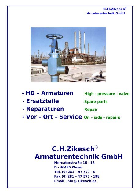
- HD – Armaturen High - pressure - valve<br />
- Ersatzteile Spare parts<br />
- Reparaturen Repair<br />
- Vor – Ort – Service On – side - repairs<br />
C.H.<strong>Zikesch</strong> ®<br />
<strong>Armaturentechnik</strong> <strong>GmbH</strong><br />
Mercatorstraße 16 - 18<br />
D - 46485 Wesel<br />
Tel. (0) 281 – 47 577 - 0<br />
Fax (0) 281 – 47 577 - 198<br />
Email Info @ zikesch.de
Zuverlässig<br />
Innovativ<br />
Kompetent<br />
Erfahren-<br />
Service<br />
Clever<br />
Händeln<br />
- Technik für die Zukunft<br />
- Qualität aus Tradition<br />
- Service Tag und Nacht<br />
C.H.<strong>Zikesch</strong> ®<br />
<strong>Armaturentechnik</strong> <strong>GmbH</strong><br />
Mercatorstraße 16 - 18<br />
D - 46485 Wesel<br />
Tel. (0) 281 – 47 577 - 0<br />
Fax (0) 281 – 47 577 - 198<br />
Email Info @ zikesch.de
Inhaltsverzeichnis<br />
Table of contents<br />
Übersicht HD – Armaturen PP-<br />
High – pressure valves programm summary<br />
HD – Absperrschieber KS-<br />
High pressure gate valve<br />
HD – Rückschlagklappe RK–<br />
High pressure swing check valve<br />
Selbstdichtender Deckelverschluß DKV-<br />
Self – sealing cover closing device<br />
Klammermuffe KLM-<br />
Clamp sleeve coupling<br />
Einspritzwasser – Regelventil ESV<br />
Injection – water control valve<br />
Mindestmengenventil MV-<br />
Minimum flow valve<br />
Drosselstrecken MVD-<br />
Throttling sections<br />
Wasser – Regelventil RVW-<br />
Water regulating valve<br />
Dampf – Regelventil RVD-<br />
Steam control valve<br />
Dampfumform – Regelventil DZe-<br />
Steam conditioning regulating valve<br />
Vorwärmerabsicherungen VW-<br />
Preheater protection<br />
Vor – Ort - Service VOS<br />
On – site - repairs<br />
Sonstiges S -<br />
other item<br />
C.H.<strong>Zikesch</strong> ®<br />
<strong>Armaturentechnik</strong> <strong>GmbH</strong>
Hochdruck – Armaturen High – pressure – valve<br />
Sicherheit ist die beste Investition<br />
Invest in safety – it`s your only alternative<br />
Sicherheit – besser sofort als später!<br />
Instandhaltung und Service spart Kosten!<br />
For safety`s sake, prevent it before it happens!<br />
Maintenance and servicing saves you money in the end!<br />
Ersatzteile<br />
spare parts<br />
Inbetriebnahme<br />
starting - up Wartung<br />
maintenance<br />
Instandhaltung<br />
repair<br />
C.H.<strong>Zikesch</strong> ®<br />
<strong>Armaturentechnik</strong> <strong>GmbH</strong><br />
Mercatorstraße 16 - 18<br />
D – 46485 Wesel<br />
Tel.: + 49(0) 281 – 47 577 - 0<br />
Fax.: + 49(0) 281 – 47 577 - 198<br />
Email: Info@zikesch.de<br />
PP-01
Invest in safety – it’s your only alternative<br />
C.H.<strong>Zikesch</strong> ®<br />
<strong>Armaturentechnik</strong> <strong>GmbH</strong><br />
Sicherheit ist<br />
die beste Investition!<br />
Seit Jahren ist unser Unternehmen auf den Bau<br />
von hochqualifizierten Armaturen für extrem hohe<br />
Druck- und Temperaturbereiche spezialisiert. Als<br />
Sonderanfertigungen sind diese Armaturen<br />
weltweit im Einsatz und gewährleisten Sicherheit,<br />
Präzision und lange Lebensdauer durch ihre<br />
besonders solide Ausführung in Material und<br />
technischer Funktion.<br />
Anwendung finden sie insbesondere in Kernkraft-<br />
werken und konventionellen Kraftwerken, in der<br />
chemischen Industrie und in der Erdöl- und<br />
Erdgasindustrie wie überhaupt in allen industriellen<br />
Anlagen, wo flüssige und flüchtige Medien<br />
verarbeitet oder transportiert werden.<br />
Unsere Baureihe der Absperrarmaturen ist grund-<br />
sätzlich für alle vorkommenden Druck- und<br />
Temperaturbereiche geeignet. Als Hochdruck -<br />
schieber, als Keil- und Parallelplattenschieber<br />
werden sie wahlweise pneumatisch oder elektrisch<br />
betätigt und sind individuell auslegbar.<br />
Die Rückschlagklappe ist als Absperrorgan für<br />
flüssige und gasförmige Medien besonders<br />
geeignet bis zu den höchsten Betriebsbedingungen.<br />
Sie ist im Aufbau unkompliziert und<br />
beansprucht nur geringen Platzbedarf; sie ist<br />
stopfbuchsenlos und wartungsfrei und kann<br />
waagerecht wie auch senkrecht eingebaut werden.<br />
Durch die stopfbuchsenlose Lagerung der<br />
Klappenwelle wird eine einwandfreie und problemlose<br />
Funktion erreicht und garantiert.<br />
Wir lösen alle<br />
Armaturenprobleme! Sprechen<br />
Sie mit uns - rufen Sie uns an!<br />
Our company has been specializing in the design and manufacture of high-test valves for extreme pressures and<br />
temperatures for over many years. These specially designed units<br />
are in operation all over the world and feature proven safety, precision and long lifetimes, combining particularly<br />
robust materials with a high degree of technical refinement.<br />
Their main areas of application include nuclear and conventional power stations, the chemical industry, the<br />
petroleum and natural gas industries - in fact, they are at home in any industrial plant where liquid and volatile<br />
media are processed or transported.<br />
Our stop valve series covers the full range of pressures and temperatures encountered in industrial environments.<br />
As high-pressure gate valves, as wedge-type flat slide valves<br />
or as parallel slide valves, they can all be either pneumatically or electrically actuated, and can also be adapted to<br />
your particular requirements.<br />
Our swing check valve is particularly suitable for shutting off liquid and gaseous media, even under the most<br />
arduous operating conditions. lt is of uncomplicated design and only takes up a minimum of space; it is also<br />
glandless and maintenance free, and can be installed either horizontally or vertically. The fact that the flap shaft<br />
bearings have no stuffing box ensures perfect and problem-free performance.<br />
We can solve all your valve problems. Just give us a ring!<br />
PP-02
Robust, betriebssicher, langlebig, servicefreundlich,<br />
das sind unsere Regelarmaturen!<br />
C.H.<strong>Zikesch</strong> ®<br />
<strong>Armaturentechnik</strong> <strong>GmbH</strong><br />
Die hervorragenden Komponenten unserer Regelarmaturen - Reihe sind das geräuscharme<br />
Dampfregelventil, das Mindestmengenventil und das Wasserregel-Ventil..<br />
Zur Absicherung von Hochdruck-Speisewasserpumpen eignet sich die Baureihe der Mindestmengenventile<br />
ganz hervorragend. In entsprechend robuster Materialauslegung fertigen wir verschiedene Baugrößen<br />
speziell für Kraftwerkseinheiten mit wahlweise elektromechanischem, hydraulischem oder auch<br />
pneumatischem Stellantrieb.<br />
Die Baureihe der Wasserregel- und Einspritz-Ventile vervollständigt unser Angebot an Regelarmaturen.<br />
Wie bei allen anderen Armaturen sind auch hier Höchstbelastungen in Druck und Temperatur selbstverständliche<br />
Eigenschaften.<br />
Wasserregel-Ventile werden in allen Industrien benötigt, wo Wasser auf niedrigen Druck entspannt werden<br />
soll. Die Ventile sind in Anpassung an vorhandene Druckgefälle in ein- und mehrstufigen Ausführungen<br />
lieferbar.<br />
Selbstverständlich stehen wir Ihnen mit allen notwendigen Detailinformationen zur Verfügung.<br />
Sprechen Sie mit uns — rufen Sie uns an!<br />
Robust, dependable, long service<br />
life, easy to maintain, our control<br />
valves are just unbeatable!<br />
Our outstanding control valve range<br />
comprises steam control valves, minimumflow<br />
control valves and water control<br />
valves.<br />
Our range of minimum - flow control valves<br />
constitutes an excellent solution for the<br />
protection of high pressure feed water<br />
pumps. We manufacture a series of robust<br />
models from purpose - matched materials<br />
which are especially designed for power<br />
station units and with a choice of electro-<br />
mechanical, hydraulic or pneumatic servo<br />
drives.<br />
Our water control and injection valves<br />
round off our control valve programme.<br />
As in the case of all our valves, these too<br />
are designed for safe and reliable<br />
operation even under the highest pressures<br />
and temperatures.<br />
Water control valves are required in all<br />
areas of industry where water pressure<br />
has to be released to a low level.<br />
And they can be matched to prevailing<br />
Pressure differentials as single and multi-<br />
Stage units.<br />
Needless to say, we will be glad to<br />
provide You with all the detailed<br />
information you Require.<br />
Just give us a ring!<br />
PP-03
C.H.<strong>Zikesch</strong> ®<br />
<strong>Armaturentechnik</strong> <strong>GmbH</strong><br />
Armaturenservice und Instandhaltung Valve service and maintenance<br />
Sicherheit – besser sofort als später! Instandhaltung und<br />
Service spart höhere Kosten!<br />
Als Hersteller kennen wir die Probleme,<br />
die bei Armaturen unter hohen Belastun-<br />
gen auftreten können. Darum haben wir<br />
zur Vermeidung und zur Behebung aller<br />
möglichen Betriebsstörungen im Armatu-<br />
renbereich eine leistungsfähige Service-<br />
und Instandhaltungsabteilung aufgebaut.<br />
aufgebaut.<br />
Ein „rund – um - die - Uhr“ abrufbares<br />
Team steht Ihnen, auch für Auslandsein-<br />
sätze, sofort zur Verfügung. Dadurch<br />
ersparen wir Ihnen unnötige Warte- und<br />
Ausfallzeiten.<br />
Unsere Ingenieure und Techniker verfüg-<br />
en über umfangreiche Erfahrungen bei<br />
allen vorkommenden Armaturenfabrikaten.<br />
Unsere Leistungen sind umfassend.<br />
„Vor - Ort-Einsatz“ wird von unseren<br />
mobilen Montagegruppen durchgeführt.<br />
Sie sind mit allen erforderlichen Spezial Werkzeugen und Maschinen ausgerüstet.<br />
Hierzu gehören auch komplett eingerichtete Werkstatt-, Maschinen- und Unterkunfts-<br />
Container.<br />
„Vor - Ort“ nicht durchführbare Reparaturen, sowie Anfertigung von Ersatzteilen, werden<br />
während Ihrer Revisionszeit termingerecht und zuverlässig in unserem Werk Essen<br />
vorgenommen.<br />
Erfahrung und Know-how als führender Hersteller von Hochdruck-Armaturen garantieren<br />
eine optimale und rasche Lösung aller anstehenden Probleme.<br />
Sprechen Sie mit uns — rufen Sie uns an!<br />
Inbetriebnahme<br />
Starting - up<br />
Ersatzteile<br />
Spare parts<br />
Instandhaltung<br />
repair<br />
Wartung<br />
maintenance<br />
For safety‘s sake, prevent it before it happens! Maintenance and servicing<br />
saves you money in the end!<br />
As manufacturers, we understand the problems which can occur with valves subjected to high operational loading.<br />
That‘s why we have developed an efficient maintenance and service package for the prevention and rectification of<br />
every possible type of valve failure.<br />
Our team is ready for your call round the clock - even for jobs abroad. And that means you save on unnecessary<br />
downtime.<br />
Our engineers and technicians are well acquainted with every conceivable valve design.<br />
We can offer a really comprehensive range of services. On - site repairs and maintenance can be carried out by<br />
our mobile crews who are equipped with all the special tools and machinery necessary for their works — including<br />
fully fitted-out portable workshops, machine containers and mobile accommodation units.<br />
Repairs which cannot be carried out on site, and also the manufacture of spare parts, will be carried out on<br />
schedule and reliably in our Essen works (FRG) while you inspect the rest of the plant.<br />
Our experience and know - how as a leading manufacturer of high - pressure valves is your guarantee that,<br />
whatever the problem, we will be able to provide the optimum solution - and do it fast.<br />
Just give us a ring! PP-04
C.H.<strong>Zikesch</strong> ®<br />
<strong>Armaturentechnik</strong> <strong>GmbH</strong><br />
HD-Armaturenprogramm–Übersicht<br />
High – Pressure Valves Program Summary<br />
Hochdruck – Absperrschieber Hochdruck – Rückschlagklappe Wasser - Einspritzregelventil<br />
High Pressure Gate Valves High Pressure Swing Check Valve Injection – water Control Valve<br />
Dampf – Regel – Ventil Wasser – Regel – Ventil Mindestmengen - Regelventil<br />
Steam Conditioning Control Valve Water Flow Control Valve Minimum Flow Valve<br />
PP-05
HD-Armaturenprogramm–Übersicht<br />
High – Pressure Valves Program Summary<br />
C.H.<strong>Zikesch</strong> ®<br />
<strong>Armaturentechnik</strong> <strong>GmbH</strong><br />
Drosselstrecke Deckelverschluß<br />
Throttle Extension Self – Sealing Cover Closing device<br />
Klammermuffe Kreuzventil<br />
Clamp Sleeve Crossing – Check Valve<br />
PP- 06
C.H.<strong>Zikesch</strong> ®<br />
<strong>Armaturentechnik</strong> <strong>GmbH</strong><br />
HD-Armaturenprogramm–Übersicht<br />
High – Pressure Valves Program Summary<br />
Vorwärmerabsicherungs – Ventile<br />
Preheater Protections<br />
3 - Wege - Umschaltventil Schnellschlußventil<br />
Three Way Valve Check Valve<br />
Instandhaltung und Service<br />
Maintenance and Servicing<br />
Inbetriebnahme<br />
starting - up<br />
Ersatzteile<br />
Spare parts<br />
Instandhaltung<br />
repair<br />
Wartung<br />
maintenance<br />
PP-07
Hochdruck –<br />
Absperrschieber<br />
High pressure gate valves<br />
Doppelplatten – Keilschieber Double plates wedge valves<br />
Doppelplatten – Parallelschieber Parallel slides<br />
Sonderausführungen<br />
Special designs<br />
C.H.<strong>Zikesch</strong> ®<br />
<strong>Armaturentechnik</strong> <strong>GmbH</strong><br />
Mercatorstraße 16 - 18<br />
D - 46485 Wesel<br />
Tel. (0) 281 – 47 577 - 0<br />
Fax (0) 281 – 47 577 - 198<br />
Email Info @ zikesch.de<br />
KS - 01
Hochdruck – Absperrschieber<br />
(Doppelplattenkeil)<br />
High pressure double plates wedge valves<br />
C.H.<strong>Zikesch</strong> ®<br />
<strong>Armaturentechnik</strong> <strong>GmbH</strong><br />
KS -02b
Doppelplatten – Keilschieber<br />
Double plates wedge gate valves<br />
Doppelplatten – Parallelschieber<br />
Parallel slides valves<br />
Sonderausführungen<br />
Special designs<br />
Aufbau und Wirkungsweise<br />
Alle Schieber sind als Doppelplatten – Keilschieber oder als<br />
Doppelplatten – Parallelschieber ausgebildet und werden für alle<br />
Druck- und Temperaturbereiche hergestellt. Sie sind in großen<br />
Stückzahlen seit ca. 50 Jahren im In- und Ausland im Betrieb.<br />
Die drucktragenden Teile bestehen aus Freiformschmiedestücken,<br />
die zu Gehäusen mit nur einer Rundnaht zusammengeschweißt<br />
werden. Größen und Nennweiten unserer Schieber finden Sie in den<br />
Maßtabellen. Langjährige Erfahrung bietet Gewähr für eine technisch<br />
ausgereifte und funktionssichere Konstruktion.<br />
Das Gehäuse des Schiebers besteht aus dem in Durchflussrichtung<br />
geschmiedeten Mittelstück. Das in Rohrform geschmiedete Kopfstück<br />
wird mit dem Mittelstück verschweißt. Nur eine Rundnaht erlaubt die<br />
exakte Prüfung der Schweißnaht durch Röntgenstrahlen, Ultraschall<br />
– oder andere Kontrollverfahren. Dadurch werden sichere<br />
Festigkeitswerte im Armaturen- Gehäuse erreicht.<br />
Der Schieberverschluß ist als selbstdichtender Deckel ausgebildet.<br />
Die Abdichtung erfolgt durch vorgepresste Grafit – Packungen.<br />
Der Schieberaufsatz ermöglicht immer den Direktaufbau eines<br />
Getriebes oder elektrischen Antriebes.<br />
Die Spindelschubkräfte werden in schweren Axial – Kugellagern und<br />
einem Radialkugellager abgefangen, die im Aufsatzkopf<br />
eingebaut sind. Die Spindeloberfläche ist auf Maß geschliffen und<br />
nachträglich durch Microfinish behandelt. Dadurch ergeben sich<br />
günstige Dicht- und Gleitverhältnisse im Packungsbereich der<br />
Spindel.<br />
C.H.<strong>Zikesch</strong> ®<br />
<strong>Armaturentechnik</strong> <strong>GmbH</strong><br />
Construction and operation<br />
All gate valves are designed as double plates gate valves or<br />
double plates parallel slides valves and are manufactured to suit<br />
all pressure and temperature ranges. They have been in operation<br />
in large numbers for over 40 years both at home and abroad.<br />
The pressurised parts consist of forgings which are welded to the<br />
body using only one circumferential weld seam. The sizes and<br />
nominal diameters of our gate valve are given in the tables of<br />
dimensions. Our many year`s experience is a guarantee of a High<br />
level of technical development and operationally safe design.<br />
The body is forged in the direction of flow to form a middle section.<br />
The bonnet section is made of forged tubing and is welded to<br />
middle section. A single circumferential weld seam enables the<br />
weld to be exactly tested by X - rays, ultrasonics or other methods.<br />
This ensures that the body has adequate strenght.<br />
The valve is sealed by means of a self – sealing cover. Pressed<br />
graphite packings are used to effect the seal.<br />
The yoke piece on top of the valves is designed in all cases to take<br />
a direct drive. The spindle thrust is absorbed bay heavy duty axial<br />
ball bearings and a radial ball bearing which are fitted in the upper<br />
part of the yoke.<br />
The spindle surface is ground to size, after which it is treated by<br />
superfinishing. This ensures the most favourable conditions for<br />
sealing and sliding in the region of the spindle packing.<br />
KS - 03
Die Dichtplatten sind in einem Plattenträger nach allen<br />
Richtungen frei pendelnd aufgehängt (s. Abb.). Die<br />
Druckübertragung erfolgt über großflächig tragende,<br />
gehärtete Kugelkalotten und Kugelpfannen, die in<br />
die Dichtplatten eingesetzt sind. Ein absolutes Dicht-<br />
schließen kann durch relativ kleine Anpresskräfte er-<br />
reicht werden. Deshalb bleiben Schließ- und Öffnungs-<br />
momente an unseren Schiebern klein.<br />
Eine Vergrößerung des Abstandes der Dichtplatten<br />
zueinander (z.B. nach Schleifarbeiten an den Dicht-<br />
flächen der Dichtringe) ist auf einfache Weise durch<br />
Hinterlegen von Zwischenscheiben hinter die Kugel-<br />
kalotten möglich.<br />
Die Verbindung von Gehäuse mit Schieberaufsatz<br />
erfolgt durch zweiteilige Klammern, die sich<br />
bei Demontage und Montage leicht lösen lassen. Druck-<br />
tragende Schraubverbindungen mit Ausnahme der Stopf-<br />
büchse werden vermieden.<br />
Alle metallisch blanken Bauteile werden vor AusIiefer-<br />
ung korrosionsgeschützt. Die Außenflächen der Armatur<br />
sind mit einer Grundfarbe versehen.<br />
Werkstoffe<br />
Werkstoffe werden nach Druck- und Temperaturbe-<br />
reichen ausgewählt. Vorzugsweise werden für die<br />
drucktragenden Teile die bekannten Kesselbau-<br />
und Rohrleitungsstähle verwendet. Die Spindeln be-<br />
stehen aus korrosionsfesten Chrom- und Chrom-<br />
Molybdän-Stählen, bei hohen Temperaturbereichen<br />
aus hochwarmfestem Chromstahl. Als Packungen<br />
werden vorgepresste Grafitringe verwendet.<br />
Die Abschlussflächen der Schieber sind grundsätzlich<br />
mit Stellit gepanzert, feinst geschliffen und geläppt.<br />
Auf Kundenwunsch werden unsere Schieber als<br />
Drosselschieber oder als Parallelschieber ausge-<br />
bildet, wobei die Anpressung der Platten beim Parallel-<br />
schieber durch warmfeste Druckfedern erfolgt.<br />
C.H.<strong>Zikesch</strong> ®<br />
<strong>Armaturentechnik</strong> <strong>GmbH</strong><br />
The sealing plates are suspended in a plate support so<br />
As to be self-aligning (see illustration).<br />
The pressure is transmitted by hardened ball segments<br />
and ball cups of large area which are inserted in the sealing<br />
discs. Absolutely tight sealing can be achieved by relatively<br />
low contact pressure. Our gate valves can therefore be<br />
opened and closed with little effort.<br />
It is possible to increase the spacing af the sealing plates<br />
(e. g. after grinding the sealing faces of the sealing rings)<br />
simply by inserting shims behind the ball segments.<br />
The yoke piece an top of the valve is connected to the<br />
body by means of a two-part clamp which can easily be<br />
disconnected when dismantling or assembling. .With the<br />
exception of the gland, there are no bolted connections<br />
under pressure.<br />
All machined metal parts are protected against corrosion<br />
before delivery. The external surface of the valve is primed.<br />
Materials<br />
Materials are chosen to suit the pressure and temperature<br />
ranges. For the pressurised parts, preference is given to<br />
the well known types of steel used in boiler and pipeline<br />
construction. The spindles are made from corrosion<br />
resistant chromium and chromemolybdenum steels, and<br />
from high heat resisting chromium steel for high<br />
temperatures. Grafit rings are used 1cr packing.<br />
The joint faces of the valve are clad in stellite, then precision<br />
ground and lapped.<br />
Our gate valves can be supplied on request as throttle<br />
valves or parallel slide valves, the contact pressure of the<br />
discs in the case of the parallel gate valves being achieved<br />
by means of heat resistant compression springs.<br />
KS -04
C.H.<strong>Zikesch</strong> ®<br />
<strong>Armaturentechnik</strong> <strong>GmbH</strong><br />
Doppelplattenkeilschieber<br />
Double plates wedge gate valves<br />
Doppelplatten – Parallelschieber Doppelplatten – Drosselschieber<br />
Double plates parallel slides valves Double plates throttle valves<br />
Plattenpaket Sealing plates KS - 05
Ausführungs-<br />
Typen<br />
Design types<br />
Mit Schweißenden Mit Entwässerungsstutzen<br />
C.H.<strong>Zikesch</strong> ®<br />
<strong>Armaturentechnik</strong> <strong>GmbH</strong><br />
Mit Stutzen für Gehäusesicherung Umführung mit Absperrventil<br />
with welded by–pass for safety valve with full by- pass and by–pass valve<br />
Mit Flansch einseitig<br />
With welded ends with drain connection with flanges accordance DIN, ANSI or other<br />
Flansche<br />
beidseitig<br />
Mit einseitig Sägegewinde für<br />
Klammerverbindung Mit angebauter Rückschlagklappe<br />
with flanges accordance DIN, ANSI or other with standards ZIKES<strong>CH</strong> clamp connection fitted with check valve<br />
Ausführungsarten - Design types<br />
mit Schweißenden mit angebauter Rückschlagklappe<br />
with welded ends fitted with check valves<br />
mit Flanschen nach DIN oder anderen Normen als Drosselschieber mit einer parallelen Dichtfläche<br />
flanges in accordance with DIN ANSI, BS or other as a throttle valve with a parallel sealing face<br />
ZIKES<strong>CH</strong>-Klammerverbindungen als Schnellschlußschieber<br />
standards ZIKES<strong>CH</strong> clamp connections as a quick action closing gate valve<br />
mit Schweißstutzen für Umführung als Schnellöffnungsschieber<br />
with welded by-pass connecting piece as a quick opening gate valve<br />
mit Entwässerungsstutzen mit mechanischer Stellungsanzeige<br />
with dram connection mit speziellen Stopfbuchsräumen<br />
mit Gehäuse-Überdrucksicherung mit Handradverriegelung<br />
with safety valve to prevent excess pressure in the bodv Unsere Schieber können mit aufgebautem<br />
mit kompletter Umführung und Umführungsventil Getriebe (Kegel- oder Stirnrad) elektrisch, pneu-<br />
KS – 04<br />
with fuII by - pass and by - pass valve matisch oder hydraulisch betätigt werden.<br />
mit Sperrwasser-Stopfbüchse Our gate valves can be supplied with drives<br />
with sealing water gland (bevel or spur gear)<br />
mit Dreifach-Stopfbüchse und Absaugung for electrical, pneumatic or hydraulic operation<br />
with triple gland and suction KS - 06
Gehäusewerkstoffe:<br />
Body material:<br />
C 22.8 (1.0460)<br />
15Mo3 (1.5415)<br />
13CrMo44 (1.7335)<br />
10CrMo910 (1.7380)<br />
15NiCuMoNb5 (1.6368)<br />
X10CrMoVNb91 (1.4903)<br />
Sonderwerkstoffe auf Anfrage<br />
Spezial material to inquiry<br />
Druckstufen: ND 63 - 640<br />
Nominal pressure NP 63 - 640<br />
Nennweiten: NW 50 – 800<br />
Nominal diameter ND 50 - 800<br />
C.H.<strong>Zikesch</strong> ®<br />
<strong>Armaturentechnik</strong> <strong>GmbH</strong><br />
KS - 07
Werkstoffe - KS<br />
Benennung Auswahl der Werkstoffe in Abhängigkeit von Auslegungstemperatur<br />
C.H.<strong>Zikesch</strong> ®<br />
<strong>Armaturentechnik</strong> <strong>GmbH</strong><br />
400°C 450°C 540°C 540°C >540°C<br />
Gehäuse C22.8 15NiCuMoNb5 15M03 13CrM044 10CrMo910 X10CrMoVN91<br />
1.0460 1,6368 1.5415 1.7335 1.7380 1.4903<br />
Sitzring<br />
Dichtplatten<br />
Plattenträger<br />
Gehäuseverschluß<br />
Spindel 1.4057/1.4122 1.4922<br />
Packungen Reingraphit<br />
Gewindebuchse Mehrstoffbronze / 1,4922 (oberflächenbehandelt)<br />
Aufsatz 1.5415 1.7335<br />
KS08
Materials - KS<br />
Description Material selection in dependence on service temperature<br />
C.H.<strong>Zikesch</strong> ®<br />
<strong>Armaturentechnik</strong> <strong>GmbH</strong><br />
400°C 450°C 540°C 540°C >540°C<br />
Casing C22.8 15NiCuMoNb5 15M03 13CrM044 10CrMo910 X10CrMoVN91<br />
1.0460 1,6368 1.5415 1.7335 1.7380 1.4903<br />
Seat ring<br />
Sealing plates<br />
Plate support<br />
Casing cover<br />
Spindle 1.4057/1.4122 1.4922<br />
Tapped bush graphite<br />
Glands multi-alloy bronze / 1,4922 (surface treated)<br />
Yoke 1.5415 1.7335<br />
KS-08a
Beispiel für einen Hochdruck-Keilplattenschieber<br />
-Nennweite DN1OO<br />
-Baureihe 01<br />
-Werkstoff Gehäuse 15Mo3<br />
-Elektro-Antrieb ohne Z - Getriebe<br />
-Umführung mit Umführungsventil<br />
und Handrad<br />
-Überdrucksicherung durch Bohrung<br />
im Keil<br />
Typenschlüssel für Hochdruckschieber<br />
DKS 100.01.2.3.2.3<br />
C.H.<strong>Zikesch</strong> ®<br />
<strong>Armaturentechnik</strong> <strong>GmbH</strong><br />
Ausführung Schieber Ausführung Entwässerung<br />
Keilplattenschieber DKS 1 ohne Entwässerungsstutzen<br />
Parallelplattenschieber DPS 2 mit Entwässerungsstutzen<br />
Drosselschieber DDS<br />
Ausführung Umführung<br />
1 ohne Umführung<br />
Nennweite DN 100 2 mit 2 Umführungsstutzen<br />
3 Umführungsventil mit Handrad<br />
4 Umführungsventil mit Antrieb<br />
5 Sonstiges<br />
<strong>Zikesch</strong>reihe 01 = PN 63 Ausführung Überdrucksicherung<br />
<strong>Zikesch</strong>reihe 02 = PN 100 1 Stutzen mit Blindkappe<br />
<strong>Zikesch</strong>reihe 03 = PN 160 2 Bohrung druckseitig im Keil<br />
Baureihe <strong>Zikesch</strong>reihe 04 = PN 250 3 Bohrung druckseitig im Sitzring<br />
<strong>Zikesch</strong>reihe 05 = PN 320 4 Stutzen mit Berstscheibe<br />
<strong>Zikesch</strong>reihe 06 = PN 400 5 Sicherheitsventil<br />
<strong>Zikesch</strong>reihe 07 = PN 500 6 Sonstiges<br />
Sonderbaureihe S > PN 500<br />
Werkstoff Gehäuse Antriebstyp<br />
C22.8 (1.0460) 1 1 Handrad ohne Zwischengetriebe<br />
15M03 (1.5415) 2 2 Handrad mit Zwischengetriebe<br />
15NiCuMoNb5 (1.6368) 3 3 Elektro-Antrieb ohne Z-Getriebe<br />
13 CrMo 4 4 (1.7335) 4 4 Elektro-Antrieb mit Z - getriebe<br />
10 CrMo 9 10 (1.7380) 5 5 Hydraulikantrieb<br />
X10 CrMoVNb 9 1 (1.4903) 6 6 Pneumatikantrieb<br />
7 Sonstiges<br />
Weitere Ausführungsvarianten:<br />
• Mechanische Stellungsanzeige<br />
• Endschalter für „Auf/Zu“ -Position<br />
• Kettenradantrieb<br />
• Abschließbare Spindel<br />
• Gepanzerte Rückdichtung<br />
• Sperring in Stopfbuchse<br />
• Kegelradgetriebe<br />
• Armaturenantrieb über Flursäule<br />
• Weitere Ausführungsvarianten auf Anfrage<br />
KS-09
Type Key for High-Pressure Slide Valve<br />
Example for a high-pressure wedge-type flat slide valve<br />
• Nominal diameter DN100<br />
• Series 01<br />
• Casing material 15Mo3<br />
• Electric drive without gear<br />
• Bypass with bypass valve and handwheel<br />
• Overpressure protection through bore in the wedge<br />
DKS 100.01.2.3.2.3<br />
C.H.<strong>Zikesch</strong> ®<br />
<strong>Armaturentechnik</strong> <strong>GmbH</strong><br />
Slide valve type Drain type<br />
Wedge-type flat slide valve DKS 1 without drain nipple<br />
Parallel-type flat slide valve DPS 2 with drain nipple<br />
Reduction slide valve DDS<br />
Bypass type<br />
1 without bypass<br />
Nominal diameter DN 100 2 2 bypass nipples<br />
3 bypass valve with handwheel<br />
4 bypass valve with drive<br />
5 divers<br />
<strong>Zikesch</strong> series 01 = PN 63 Overpressure protection<br />
<strong>Zikesch</strong> series 02 = PN 100 1 nipple with blind cap<br />
<strong>Zikesch</strong> series 03 = PN 160 2 bore upstream in wedge<br />
Series <strong>Zikesch</strong> series 04 = PN 250 3 bore upstream in seat ring<br />
<strong>Zikesch</strong> series 05 = PN 320 4 nipple with bursting disk<br />
<strong>Zikesch</strong> series 06 = PN 400 5 safety valve<br />
<strong>Zikesch</strong> series 07 = PN 500 6 divers<br />
Special series S > PN 500<br />
Casing material Drive Type<br />
C22.8 (1.0460) 1 1 handwheel without gear<br />
15 Mo3 (1.5415) 2 2 geared handwheel<br />
15 NiCuMoNb5 (1.6368) 3 3 electric drive without gear<br />
13 CrMo 4 4 (1.7335) 4 4 geared electric drive<br />
10 CrMo 9 10 (1.7380) 5 5 hydraulic drive<br />
X10 CrMoVNb 9 1 (1.4903) 6 6 pneumatic drive<br />
7 divers<br />
Further types:<br />
• Mechanical position indicator<br />
• Limit switch ON/OFF position<br />
• Chain wheel drive<br />
• Lockable spindle<br />
• Armored sealing<br />
• Stop ring in gland<br />
• Bevel gear<br />
• Valve drive through floor pedestal<br />
KS-09a
Maßtabelle DIN<br />
Maße in mm<br />
Table of dimensions DIN<br />
Dimensions in millimetres<br />
C.H.<strong>Zikesch</strong> ®<br />
<strong>Armaturentechnik</strong> <strong>GmbH</strong><br />
ND/NP NW/ND L H1 H2 Fø b Aø U/Hub Turns to lift<br />
64 50 50 250 430 495 180 26 250 12<br />
64 65 50 290 430 495 205 26 250 12<br />
64 65 65 290 460 540 205 26 250 13<br />
64 80 65 310 460 540 215 28 250 13<br />
64 80 80 310 490 580 215 28 360 18<br />
64 100 80 350 490 580 250 30 360 18<br />
64 100 100 350 555 660 250 30 450 21<br />
64 125 100 400 555 660 295 34 450 21<br />
64 125 125 400 645 770 295 34 450 25<br />
64 150 125 400 645 770 345 36 450 25<br />
64 150 150 450 725 885 345 36 450 32<br />
64 175 150 450 725 885 375 40 450 32<br />
64 175 175 500 815 995 375 40 520 30<br />
64 200 175 500 815 995 415 42 520 30<br />
64 200 200 550 905 1110 415 42 640 34<br />
64 250 200 600 905 1110 470 46 640 34<br />
64 225 225 600 960 1190 - - 720 38,5<br />
64 250 225 600 960 1190 470 46 720 38,5<br />
64 250 250 650 1025 1280 470 46 720 42,5<br />
64 300 250 700 1025 1280 530 52 720 42,5<br />
64 275 275 700 1115 1395 - - 800 40<br />
64 300 275 750 1115 1395 530 52 800 40<br />
64 300 300 750 1175 1475 530 52 800 43<br />
64 350 300 800 1175 1475 600 56 800 43<br />
64 350 350 850 1420 1780 600 56 900 40<br />
64 400 350 900 1420 1780 670 60 900 40<br />
64 400 400 950 1580 1990 670 60 1000 45,5<br />
64 450 400 1000 1580 1990 - - 1000 45,5<br />
64 450 450 1100 1720 2180 - - 1000 51<br />
64 500 450 1100 1720 2180 - - 1000 51<br />
64 500 500 1150 1865 2380 - - 1000 57<br />
64 550 500 1150 1865 2380 - - 1000 57<br />
64 600 500 1200 1865 2380 - - 1000 57<br />
64 550 550 1300 2150 2710 - - 1000 56<br />
64 600 550 1300 2150 2710 - - 1000 56<br />
64 600 600 1400 2220 2820 - - 1000 72<br />
Sonderbaulänge auf Anfrage• Größere Nennweiten auf Anfrage<br />
Special overall lenghts on request – Larger nominal diameter on request KS-10
Maßtabelle<br />
DIN<br />
Maße in mm<br />
Table of dimensions DIN<br />
Dimensions in millimetres<br />
C.H.<strong>Zikesch</strong> ®<br />
<strong>Armaturentechnik</strong> <strong>GmbH</strong><br />
ND/NP NW/ND L H1 H2 Fø b Aø U/Hub Turns to lift<br />
100 50 50 250 430 495 195 28 250 12<br />
100 65 50 290 430 495 220 30 250 12<br />
100 65 65 290 460 540 220 30 360 13<br />
100 80 65 310 460 540 230 32 360 13<br />
100 80 80 310 530 620 230 32 450 18<br />
100 100 80 350 530 620 265 36 450 18<br />
100 100 100 350 580 686 265 36 450 21<br />
100 125 100 400 580 686 315 40 450 21<br />
100 125 125 400 670 805 315 40 520 27<br />
100 150 125 400 670 805 355 44 520 27<br />
100 150 150 450 765 923 355 44 640 26,5<br />
100 175 150 450 765 923 385 48 640 26,5<br />
100 175 175 500 835 1015 385 48 720 30<br />
100 200 175 500 835 1015 430 52 720 30<br />
100 200 200 550 905 1110 430 52 800 34<br />
100 250 200 600 905 1110 505 60 800 34<br />
100 225 225 600 980 1218 - - 900 34<br />
100 250 225 600 980 1218 505 60 900 34<br />
100 250 250 650 1050 1302 505 60 900 36<br />
100 300 250 700 1050 1302 585 68 900 36<br />
100 275 275 700 1130 1410 - - 900 35<br />
100 300 275 750 1130 1410 585 68 900 35<br />
100 300 300 750 1215 1515 585 68 900 37,5<br />
100 350 300 800 1215 1515 655 74 900 37,5<br />
100 350 350 850 1420 1780 655 74 1000 40<br />
100 400 350 900 1420 1780 - - 1000 40<br />
100 400 400 900 1580 1990 - - 1000 45,5<br />
100 450 400 1000 1580 1990 - - 1000 45,5<br />
100 450 450 1050 1720 2180 - - 1000 51<br />
100 500 450 1100 1720 2180 - - 1000 51<br />
100 500 500 1150 1880 2395 - - 1000 57<br />
100 550 500 1150 1880 2395 - - 1000 57<br />
100 600 500 1250 1880 2395 - - 1000 57<br />
100 550 550 1300 2200 2770 - - 1000 57<br />
100 600 550 1300 2200 2770 - - 1000 57<br />
100 600 600 1400 2520 3140 - - 1000 62<br />
Sonderbaulänge auf Anfrage• Größere Nennweiten auf Anfrage<br />
Special overall lenghts on request – Larger nominal diameter on request KS-11
Maßtabelle<br />
DIN<br />
Maße in mm<br />
Table of dimensions DIN<br />
Dimensions in millimetres<br />
C.H.<strong>Zikesch</strong> ®<br />
<strong>Armaturentechnik</strong> <strong>GmbH</strong><br />
ND/NP NW/ND L H1 H2 Fø b Aø U/Hub Turns to lift<br />
160 50 50 300 430 495 195 30 250 12<br />
160 65 50 360 430 495 220 34 250 12<br />
160 65 65 360 510 590 220 34 360 16<br />
160 80 65 390 510 590 230 36 360 16<br />
160 80 80 390 530 620 230 36 520 18<br />
160 100 80 450 530 620 265 40 520 18<br />
160 100 100 400 580 685 265 40 640 21<br />
160 125 100 450 580 685 315 44 640 21<br />
160 125 125 500 670 805 315 44 720 22,5<br />
160 150 125 500 670 805 355 50 720 22,5<br />
160 150 150 550 780 940 355 50 720 26,5<br />
160 175 150 600 780 940 390 54 720 26,5<br />
160 175 175 650 835 1015 390 54 800 30<br />
160 200 175 700 835 1015 430 60 800 30<br />
160 200 200 750 945 1150 430 60 900 30<br />
160 250 200 800 945 1150 515 68 900 30<br />
160 225 225 800 1045 1285 - - 900 30<br />
160 250 225 800 1045 1285 515 68 900 30<br />
160 250 250 850 1095 1350 515 68 1000 32<br />
160 300 250 900 1095 1350 585 78 1000 32<br />
160 275 275 900 1190 1470 - - 1000 31<br />
160 300 275 900 1190 1470 585 78 1000 31<br />
160 300 300 900 1285 1590 585 78 1000 34<br />
160 350 300 950 1285 1590 - - 1000 34<br />
160 350 350 1000 1495 1855 - - 1000 40<br />
160 400 350 1050 1495 1855 - - 1000 40<br />
160 400 400 1100 1655 2065 - - 1000 45,5<br />
160 450 400 1100 1655 2065 - - 1000 45,5<br />
160 450 450 1200 1750 2210 - - 1000 46<br />
160 500 450 1200 1750 2210 - - 1000 46<br />
160 500 500 1250 1830 2345 - - 1000 51,5<br />
160 550 500 1300 1830 2345 - - 1000 51,5<br />
160 600 500 1300 1830 2345 - - 1000 51,5<br />
160 550 550 1300 2400 2970 - - 1000 47,5<br />
160 600 550 1300 2400 2970 - - 1000 47,5<br />
160 600 600 1400 2740 3320 - - 1000 48<br />
Sonderbaulänge auf Anfrage• Größere Nennweiten auf Anfrage<br />
Special overall lenghts on request – Larger nominal diameter on request KS-12
Maßtabelle<br />
DIN<br />
Maße in mm<br />
Table of dimensions DIN<br />
Dimensions in millimetres<br />
C.H.<strong>Zikesch</strong> ®<br />
<strong>Armaturentechnik</strong> <strong>GmbH</strong><br />
ND/NP NW/ND L H1 H2 Fø b Aø U/Hub Turns to lift<br />
250 50 50 350 430 495 200 38 360 13<br />
250 65 50 400 430 495 230 42 360 13<br />
250 65 65 400 515 595 230 42 450 16<br />
250 80 65 450 515 595 255 46 450 16<br />
250 80 80 450 560 650 255 46 520 18<br />
250 100 80 500 560 650 300 54 520 18<br />
250 100 100 500 645 760 300 54 720 19<br />
250 125 100 600 645 760 340 60 720 19<br />
250 125 125 650 705 840 340 60 800 22,5<br />
250 150 125 650 705 840 390 68 800 22,5<br />
250 150 150 700 780 940 390 68 800 26,5<br />
250 175 150 800 780 940 430 74 800 26,5<br />
250 175 175 850 920 1110 430 74 900 27<br />
250 200 175 900 920 1110 485 82 900 27<br />
250 200 200 950 1050 1270 485 82 900 27,5<br />
250 250 200 950 1050 1270 585 100 900 27,5<br />
250 225 225 1000 1140 1380 - - 1000 26,5<br />
250 250 225 1000 1140 1380 585 100 1000 26,5<br />
250 250 250 1100 1185 1445 585 100 1000 29<br />
250 300 250 1150 1185 1445 690 120 1000 29<br />
250 275 275 1250 1280 1565 - - 1000 31,5<br />
250 300 275 1250 1280 1565 690 120 1000 31,5<br />
250 300 300 1250 1340 1655 690 120 1000 35<br />
250 350 300 1250 1340 1655 - - 1000 35<br />
250 350 350 1400 1625 2005 - - 1000 38<br />
250 400 350 1400 1625 2005 - - 1000 38<br />
250 400 400 1450 1850 2285 - - 1000 43,5<br />
250 450 400 1450 1850 2285 - - 1000 43,5<br />
250 450 450 1500 1950 2420 - - 1000 47<br />
Sonderbaulänge auf Anfrage - Größere Nennweiten auf Anfrage<br />
Special overall lenghts on request – Larger nominal diameter on request<br />
KS-13
Maßtabelle<br />
DIN<br />
Maße in mm<br />
Table of dimensions DIN<br />
Dimensions in millimetres<br />
C.H.<strong>Zikesch</strong> ®<br />
<strong>Armaturentechnik</strong> <strong>GmbH</strong><br />
ND/NP NW/ND L H1 H2 Fø b Aø U/Hub Turns to lift<br />
320 50 50 350 495 560 210 42 360 13<br />
320 65 50 425 495 560 255 51 360 13<br />
320 65 65 425 535 615 255 51 450 16<br />
320 80 65 470 535 615 275 55 450 16<br />
320 80 80 470 565 655 275 55 520 18<br />
320 100 80 550 565 655 335 65 520 18<br />
320 100 100 550 645 760 335 65 720 19<br />
320 125 100 650 645 760 380 75 720 19<br />
320 125 125 650 715 850 380 75 800 22,5<br />
320 150 125 750 715 850 425 84 800 22,5<br />
320 150 150 750 855 1025 425 84 900 24<br />
320 175 150 850 855 1025 485 95 900 24<br />
320 175 175 850 945 1135 485 95 1000 24<br />
320 200 175 950 945 1135 525 103 1000 24<br />
320 200 200 950 1065 1285 525 103 1000 24,5<br />
320 250 200 1150 1065 1285 640 125 1000 24,5<br />
320 225 225 1050 1165 1405 - - 1000 26,5<br />
320 250 225 1150 - - 640 125 1000 26,5<br />
320 250 250 1150 1255 1525 640 125 1000 30<br />
320 300 250 1350 1255 1525 - - 1000 30<br />
320 275 275 1250 1330 1620 - - 1000 29<br />
320 300 275 1350 1330 1620 - - 1000 29<br />
320 300 300 1350 1405 1730 - - 1000 32,5<br />
320 350 300 1350 1405 1730 - - 1000 32,5<br />
320 350 350 1500 1600 1975 - - 1000 37,5<br />
320 400 350 1500 1600 1975 - - 1000 37,5<br />
320 400 400 1600 1825 2265 - - 1000 44<br />
320 450 400 1600 1825 2265 - - 1000 44<br />
320 450 450 1700 2110 2620 - - 1000 42,5<br />
Sonderbaulänge auf Anfrage - Größere Nennweiten auf Anfrage<br />
Special overall lenghts on request – Larger nominal diameter on request KS-14
Maßtabelle<br />
DIN<br />
Maße in mm<br />
Table of dimensions DIN<br />
Dimensions in millimetres<br />
C.H.<strong>Zikesch</strong> ®<br />
<strong>Armaturentechnik</strong> <strong>GmbH</strong><br />
ND/NP NW/ND L H1 H2 Fø b Aø U/Hub Turns to lift<br />
400 50 50 350 495 560 235 52 450 13<br />
400 65 50 425 495 560 290 64 450 13<br />
400 65 65 425 535 615 290 64 520 16<br />
400 80 65 450 535 615 305 68 520 16<br />
400 80 80 450 580 670 305 68 640 18<br />
400 100 80 500 580 670 370 80 640 18<br />
400 100 100 550 660 775 370 80 800 19<br />
400 125 100 600 660 775 415 92 800 19<br />
400 125 125 600 825 970 415 92 900 20,5<br />
400 150 125 700 825 970 475 105 900 20,5<br />
400 150 150 750 920 1090 475 105 1000 21,5<br />
400 175 150 800 920 1090 545 120 1000 21,5<br />
400 175 175 850 1025 1220 545 120 1000 21,5<br />
400 200 175 900 1025 1220 585 130 1000 21,5<br />
400 200 200 950 1140 1365 585 130 1000 25<br />
400 250 200 1000 1140 1365 - - 1000 25<br />
400 225 225 1050 1240 1500 - - 1000 29<br />
400 250 225 1050 1240 1500 - - 1000 29<br />
400 250 250 1150 1295 1575 - - 1000 33,5<br />
400 300 250 1250 1295 1575 - - 1000 33,5<br />
400 275 275 1250 1410 1700 - - 1000 29<br />
400 300 275 1300 1410 1700 - - 1000 29<br />
400 300 300 1350 1435 1765 - - 1000 33<br />
400 350 300 1350 1435 1765 - - 1000 33<br />
400 350 350 1400 1675 2065 - - 1000 39<br />
400 400 350 1400 1675 2065 - - 1000 39<br />
400 400 400 1500 1800 2220 - - 1000 35<br />
400 450 400 1500 1800 2220 - - 1000 35<br />
400 450 450 1600 2000 2500 - - 1000 41,5<br />
Sonderbaulänge auf Anfrage - Größere Nennweiten auf Anfrage<br />
Special overall lenghts on request – Larger nominal diameter on request KS-15
C.H.<strong>Zikesch</strong><br />
<strong>Armaturentechnik</strong> <strong>GmbH</strong><br />
Maximale Betriebsdrücke für Hochdruckschieber und Rückschlagklappen<br />
Werkstoff Baureihe Maximaler Betriebsdruck (bar) in Abhängigkeit der Betriebstemperatur °C)*<br />
(°C)) 20 50 100 150 200 250 300 350 400 425 450 460 470 480 490 500 510 515 520 525 530 535 540 545 550 560<br />
01 85 84 81 74 65 58 51 44 35<br />
02 127 124 113 100 89 78 67 54<br />
03 202 185 163 145 127 110 88<br />
C22.8 04 bar 287 252 225 198 170 136<br />
(1.0460) 05 323 288 253 218 174<br />
06 361 317 273 218<br />
07 395 341 273<br />
08<br />
SB<br />
435 348<br />
01 101 96 88 81 74 69 60 56 53 52 51 51 50 50 41 32<br />
02 147 135 124 113 105 91 86 81 79 78 77 77 76 62 48<br />
03 220 202 185 171 149 141 132 129 127 126 126 125 101 79<br />
15Mo3 04 bar 314 287 266 232 218 205 201 198 198 195 194 157 123<br />
(1.5415) 05 367 341 297 279 262 258 253 251 250 248 201 157<br />
06 426 372 350 328 322 317 315 312 310 252 196<br />
07 464 436 409 402 395 393 390 387 314 245<br />
08<br />
SB<br />
556 522 513 504 501 497 494 400 313<br />
01 135 135 135 135 135 132 129 125 118 111 87<br />
02 206 206 206 201 196 191 180 169 132<br />
03 335 335 328 319 311 293 275 215<br />
15NiCuMoNb5 04 bar 521 509 496 482 455 427 334<br />
(1.6368) 05 652 635 617 582 546 428<br />
06 794 772 728 683 536<br />
07 909 853 669<br />
08<br />
SB<br />
852<br />
KS-16<br />
*)Die angegebenen maximalen Betriebsdrücke können von den genannten Drücken abweichen. Die verbindliche Auswahl des Schiebers/ der Rückschlagklappe legt der Hesteller fest.
C.H.<strong>Zikesch</strong><br />
<strong>Armaturentechnik</strong> <strong>GmbH</strong><br />
Maximale Betriebsdrücke für Hochdruckschieber und Rückschlagklappen<br />
Werkstoff Baureihe Maximaler Betriebsdruck (bar) in Abhängigkeit der Betriebstemperatur °C)*<br />
(°C)) 20 50 100 150 200 250 300 350 400 425 450 460 470 480 490 500 510 515 520 525 530 535 540 545 550 560<br />
01 64 63 62 61 60 60 58 48 41 36 32 29 26 23 21 19<br />
02 96 94 93 92 91 88 74 62 55 49 44 40 36 32 28<br />
03 154 152 150 148 143 120 101 90 80 72 65 59 52 47<br />
13CrMo44 04 bar 236 233 231 222 187 157 141 124 113 101 91 82 73<br />
(1.7335) 05 299 295 285 221 201 180 159 144 130 117 104 93<br />
06 369 356 299 252 225 199 181 162 147 131 116<br />
07 374 314 281 249 226 203 183 163 145<br />
08<br />
SB<br />
359 317 288 258 233 208 185<br />
01 69 67 65 65 64 60 54 48 41 39 36 34 32 29 27 25 24<br />
02 102 100 99 97 91 82 68 63 59 55 52 48 45 42 39 36<br />
03 163 161 159 149 133 118 111 97 90 85 79 74 68 64 59<br />
10CrMo910 04 bar 250 247 232 207 184 172 151 140 131 123 114 106 99 92<br />
(1.7380) 05 316 297 265 236 206 193 180 168 157 146 136 127 118<br />
06 372 332 276 258 241 225 211 196 183 170 159 148<br />
07 415 368 322 301 281 263 245 229 213 199 185<br />
08<br />
SB<br />
469 410 384 358 335 313 292 271 254 236<br />
01 128 122 117 114 109 101 92 83 75 70 66 62 59 55 52 48 45 42<br />
02 186 178 174 167 153 140 127 114 107 100 95 90 84 79 74 69 65<br />
03 290 283 272 250 229 207 201 174 163 155 147 138 129 121 112 100<br />
X10CrMoVNb91 04 bar 440 422 388 355 321 313 271 254 241 228 214 200 187 174 150<br />
(1.4903) 05 540 496 454 400 369 347 325 308 292 274 257 240 223 200<br />
06 621 569 514 461 434 407 386 365 343 321 300 280 255<br />
07 710 641 576 542 507 482 456 428 401 375 349 320<br />
08<br />
SB<br />
817 734 690 647 614 581 546 511 478 445 410<br />
KS-17<br />
*)Die angegebenen maximalen Betriebsdrücke können von den genannten Drücken abweichen. Die verbindliche Auswahl des Schiebers/ der Rückschlagklappe legt der Hesteller fest.
Hochdruck –<br />
Rückschlagklappe<br />
High Pressure Swing Check Valve<br />
C.H.<strong>Zikesch</strong> ®<br />
<strong>Armaturentechnik</strong> <strong>GmbH</strong><br />
Mercatorstraße 16 - 18<br />
D - 46485 Wesel<br />
Tel. (0) 281 – 47 577 - 0<br />
Fax (0) 281 – 47 577 - 198<br />
Email Info @ zikesch.de
C.H.<strong>Zikesch</strong> ®<br />
<strong>Armaturentechnik</strong> <strong>GmbH</strong><br />
Hochdruck – Rückschlagklappe<br />
High pressure Swing Check Valve<br />
RK -02b
Rückschlagklappe Typ RK<br />
Swing Check Valve Type RK<br />
C.H.<strong>Zikesch</strong> ®<br />
<strong>Armaturentechnik</strong> <strong>GmbH</strong><br />
Vorzüge: Advantages:<br />
- unkomplizierter Aufbau - simple construktion<br />
- geringer Platzbedarf - needs minimum space<br />
- stopfbuchslos - needs no gland<br />
- wartungsfrei - needs no maintenance<br />
- waagerechte und senkrechte - horizontal and vertical mountings<br />
Einbaulagen<br />
- beizfest - acid resistant<br />
1.Verwendungszweck<br />
Die Rückschlagklappe ist ein Absperrorgan, das entwickelt wurde für Speisewasserleitungen an Hochdruck-<br />
Kesseln und Hochdruck-Pumpen. Die Rückschlagklappe öffnet sich bei beginnender Förderung durch die<br />
Strömungskräfte des Durchflußmediums selbständig.Sie schließt bei Strömungsunterbrechung infolge<br />
Schwerkraftwirkung des Klappentellers und Einwirkung des Rückdruckes entgegen der Durchflußrichtung.<br />
Durch die stopfbuchslose Lagerung der Klappenwelle ist eine einwandfreie und leichte Funktion garantiert.<br />
Auch ist ein Undichtwerden wegen Fehlen der Stopfbuchse unmöglich. Die Rückschlagklappe ist grundsätzlich<br />
mit selbstdichtendem Deckelverschluß ausgerüstet. Sie wird auch als Rückflußsicherung in Heißdampfleitungen<br />
und Fernleitungen mit höchsten Drücken verwendet.<br />
2. Ausführungsarten<br />
Mit Schweißenden, wie im Prospekt abgebildet,<br />
mit Flanschen,<br />
mit Schweißenden einerseits, Flanschen andererseits,<br />
einerseits Schweißenden, andererseits Wulst- oder Gewindestutzen für ZIKES<strong>CH</strong>– Klammermuffen - Anschluß,<br />
mit Mindestmengenabzweig vor dem Klappenteller, mit Entlastungsstutzen hinter dem Klappenteller;<br />
Sonderwünsche werden berücksichtigt.<br />
3. Aufbau und Wirkungsweise<br />
Das Gehäuse der Rückschlagklappe ist aus einem Schmiedestahlblock gearbeitet Die Wandstärke ist<br />
entsprechend Druck und Temperatur bis 650 °C bemessen. Der den Rückstrom absperrende Teller ist mit<br />
geringem axialem und radialem Spiel im Klappenhebel gelagert und mit Mutter gehalten. Der Klappenhebel<br />
wiederum kann um die Welle frei schwenken. Die Lagerung der beweglichen Teile in der Lagerplatte wird<br />
getrennt von den Abdichtorganen durchgeführt. Die Schraube wird nach dem Anziehen gesichert und drückt die<br />
Platte fest gegen den vierteiligen Sprengring, welcher dadurch gegen Herausgleiten gesichert ist. Der<br />
Zylinderstift verhindert ein seitliches Verdrehen der Lagerplatte. Die Abdichtung des Gehäuses erfolgt durch<br />
einen selbstdichtenden Deckelverschluß.<br />
Durch die Konstruktion ist gewährleistet, daß der Klappenteller schon in drucklosem Zustand fest auf dem Sitz<br />
aufliegt, auch im waagerechten Einbau. Die Rückschlagklappe kann in waagerechte und senkrechte Leitungen<br />
eingebaut werden, wobei bei senkrechtem Einbau zu beachten ist, daß die Durchströmung von unten nach<br />
oben erfolgt. Das Einschweißen der Armatur und Glühen der Nähte kann ohne Demontage der Innenteile<br />
erfolgen. Ohne Gefährdung der Innenteile können unsere Rückschlagklappen gebeizt werden.<br />
RK-03
Swing Check Valve Type RK<br />
1. Application<br />
C.H.<strong>Zikesch</strong> ®<br />
<strong>Armaturentechnik</strong> <strong>GmbH</strong><br />
The check valve is a shut off device, developed for feed-water piping in high-pressure boilers and pumps.<br />
The check valve opens, automatically caused by the flow of the medium and shuts due to the gravity effect of<br />
the swing plate causing counter-pressure in case of flow interruption. Thanks to the glandless fitting of the<br />
valve shaft, a trouble-free and simple operation is guaranteed. Furthermore, needing no gland, leakage is<br />
quite impossible. The check valve is basically equipped with a self-sealing cover-plate. lt is also employed as<br />
a safety device to check reverse-flow in pipelines carrying superheated steam and in long distance pipes<br />
systems with highest pressure ranges.<br />
2) Available connections<br />
Fabricated with welded ends (as shown in the leaflet) with flanges, to meet specs, one side with welded<br />
ends, and other side with flanges, one side with welded ends, and other side butt-end or threaded end for<br />
ZIKES<strong>CH</strong>-Cramp Socket-connection, with minimum flow connection up streams of the valve plate and relief<br />
nozzle downstream of the valve plate. Special requirements are considered.<br />
3) Construction and operation<br />
The Check-Valve casing is fabricated out of solid forged steel piece. The wall thickness is designed for<br />
maximum pressure rating and temperature up to 650°C. The Swing check to stop reverse-flow is mounted in<br />
the disc-lever with little axial and radial play and held by screw nuts. The disc-lever can turn freely round the<br />
shaft. The movable parts of the disc are fitted separately from the sealing parts. After tightening, the screw is<br />
secured and presses the disc firmly against the four-parted thrust ring thus protecting against slipping. The<br />
cylindrical pin prevents a horizontal displacement of disc. The casing is provided with a self-sealing coverplate.<br />
This construction guarantees that the valve disc fits firmly even when no pressure is acting, also in a<br />
horizontal and vertical piping, where as in vertical installation it must be made certain that the flow is in the<br />
direction from bottom to top. The welding of the valve and heat treatment of the seams may be carried out<br />
without removing the internals. The Check Valves may be pickled without harming the internals.<br />
RK-04
Standardausführung mit<br />
Schweißenden<br />
Standard version with butt-weld ends<br />
Mit Steuerzylinder, Stellungs-<br />
Anzeige, Hebel und Gewicht<br />
With Actuator cylinder, position<br />
indicator, lever, and weight<br />
Ausführung mit<br />
Mindestmengenabzweig<br />
Type with bleed branch<br />
Mit Dämpfungszylinder, Hebel<br />
und Gewicht<br />
With stabilizing cylinder, lever and weight<br />
C.H.<strong>Zikesch</strong> ®<br />
<strong>Armaturentechnik</strong> <strong>GmbH</strong><br />
Ausführungs-<br />
Typen<br />
Design Types<br />
Mit angebautem Schieber<br />
With installed slide<br />
Weitere Ausführungsarten:<br />
- mit Flanschen nach DIN und anderen Normen With flanges to DIN and other standards<br />
- Mit <strong>Zikesch</strong> – Klammerverbindung With <strong>Zikesch</strong> clamp connection<br />
- Mit Mindestmengenabzweigstutzen vor dem Klappenteller,<br />
- With bleed socket in front of gate cover<br />
- Mit Entwässerungsstutzen hinter dem Klappenteller With drain socket behind gate cover<br />
- Mit mechanischer Stellungsanzeige, mit oder ohne End – Signalschalter<br />
- With mechanical position indicator, with or without limit Stopp switch on protruding shaft at the side<br />
with gland<br />
durch seitlich herausgeführte Welle mit Stopfbuchse<br />
- mit speziellen Stopfbuchsräumen (Kernkraftausführung) With spezial gland packing boxes<br />
- mit Hebel und Gewicht bei herausgeführter Welle mit Stopfbuchse With lever ans weight at<br />
raised shaft with packing gland<br />
- mit seitlichem Dämpfungszylinder oder Steuerzylinder, with lateral stabilizing cylinder or actuator<br />
cylinder, pneumatically or hydraulically driven, with raised shaft with packing gland<br />
pneumatisch oder hydraulisch, bei herausgeführter Welle mit Stopfbuchse<br />
RK-05
Werkstoffe – RK<br />
Gehäusewerkstoffe für Gehäuse: 1.0460; 1.5415; 1.7335; 1.7380; 1.6368; 1.4903; Sonderwerkstoffe auf Anfrage<br />
Body material Special material to inquiry<br />
Benennung Auswahl der Werkstoffe in Abhängigkeit von Auslegungstemperatur<br />
C.H.<strong>Zikesch</strong> ®<br />
<strong>Armaturentechnik</strong> <strong>GmbH</strong><br />
Material – RK<br />
Body material: 1.0460; 1.5415; 1.7335; 1.7380; 1.6368; 1.4903; Special material to inquiry<br />
Description Material selection in dependence on service temperature<br />
C.H.<strong>Zikesch</strong> ®<br />
<strong>Armaturentechnik</strong> <strong>GmbH</strong><br />
C.H.<strong>Zikesch</strong> ®<br />
<strong>Armaturentechnik</strong> <strong>GmbH</strong><br />
Maßtabelle DIN<br />
Maße in mm<br />
Table of dimensions DIN<br />
Dimensions in millimetres<br />
ND/NP NW/ND L1=L2 H HA F b<br />
64 50 250 165 340 180 26<br />
64 65 290 185 400 205 26<br />
64 80 310 205 460 215 28<br />
64 100 350 225 520 250 30<br />
64 125 400 260 600 295 34<br />
64 150 450 310 690 345 36<br />
64 175 500 340 780 375 40<br />
64 200 550 370 870 415 42<br />
64 225 600 400 960 - -<br />
64 250 650 440 1050 470 46<br />
64 275 700 480 1150 - -<br />
64 300 750 530 1250 530 52<br />
64 350 850 590 1400 600 56<br />
64 400 950 660 1550 670 60<br />
100 50 250 165 340 195 28<br />
100 65 290 185 400 220 30<br />
100 80 310 205 460 230 32<br />
100 100 350 225 520 265 36<br />
100 125 400 260 600 315 40<br />
100 150 450 310 690 355 44<br />
100 175 500 340 780 385 48<br />
100 200 550 370 870 430 52<br />
100 225 600 400 960 - -<br />
100 250 650 440 1050 505 60<br />
100 275 700 480 1150 - -<br />
100 300 750 530 1250 585 68<br />
100 350 850 590 1400 655 74<br />
100 400 950 660 1550 - -<br />
160 50 300 165 340 195 30<br />
160 65 360 185 400 220 34<br />
160 80 390 205 460 230 36<br />
160 100 450 225 520 265 40<br />
160 125 525 260 600 315 44<br />
160 150 600 310 690 355 50<br />
160 175 675 340 780 390 54<br />
160 200 750 370 870 430 60<br />
160 225 825 400 960 - -<br />
160 250 900 440 1050 515 68<br />
160 275 975 480 1150 - -<br />
160 300 1000 530 1250 585 78<br />
160 350 1050 590 1400 - -<br />
160 400 1100 660 1550 - -<br />
Sonderbaulänge auf Anfrage• Größere Nennweiten auf Anfrage<br />
Special overall lenghts on request – Larger nominal diameter on request RK-07
C.H.<strong>Zikesch</strong> ®<br />
<strong>Armaturentechnik</strong> <strong>GmbH</strong><br />
Maßtabelle DIN<br />
Maße in mm<br />
Table of dimensions DIN<br />
Dimensions in millimetres<br />
ND/NP NW/ND L1=L2 H HA F b<br />
250 50 350 175 350 200 38<br />
250 65 425 195 410 230 42<br />
250 80 470 220 475 255 46<br />
250 100 550 245 540 300 54<br />
250 125 650 285 620 340 60<br />
250 150 750 335 720 390 68<br />
250 175 850 365 810 430 74<br />
250 200 950 400 900 485 82<br />
250 225 1050 430 990 - -<br />
250 250 1150 460 1080 585 100<br />
250 275 1250 520 1200 - -<br />
250 300 1350 570 1300 - -<br />
250 350 1400 620 1450 - -<br />
250 400 1450 680 1600 - -<br />
320 50 350 175 350 210 42<br />
320 65 425 195 410 255 51<br />
320 80 470 220 475 275 55<br />
320 100 550 245 540 335 65<br />
320 125 650 285 620 380 75<br />
320 150 750 335 720 425 84<br />
320 175 850 365 810 485 95<br />
320 200 950 400 900 525 103<br />
320 225 1050 430 990 - -<br />
320 250 1150 460 1080 640 125<br />
320 275 1250 520 1200 - -<br />
320 300 1350 570 1300 - -<br />
320 350 1500 620 1450 - -<br />
320 400 1600 680 1600 - -<br />
400 50 350 185 360 235 52<br />
400 65 425 205 420 290 64<br />
400 80 470 230 485 305 68<br />
400 100 550 255 550 370 80<br />
400 125 650 295 630 415 92<br />
400 150 750 350 735 475 105<br />
400 175 850 380 830 - -<br />
400 200 950 420 920 585 130<br />
400 225 1050 450 1010 - -<br />
400 250 1150 480 1100 - -<br />
400 275 1250 540 1220 - -<br />
400 300 1350 600 1330 - -<br />
400 350 1500 650 1480 - -<br />
Sonderbaulänge auf Anfrage• Größere Nennweiten auf Anfrage<br />
Special overall lenghts on request – Larger nominal diameter on request RK-08
C.H.<strong>Zikesch</strong> ®<br />
<strong>Armaturentechnik</strong> <strong>GmbH</strong><br />
Selbstdichtender Deckelverschluß Typ SDV<br />
Self – sealing cover closing device Typ SDV<br />
C.H.<strong>Zikesch</strong> ®<br />
<strong>Armaturentechnik</strong> <strong>GmbH</strong><br />
Mercatorstraße 16 - 18<br />
D - 46485 Wesel<br />
Tel. (0) 281 – 47 577 - 0<br />
Fax (0) 281 – 47 577 - 198<br />
Email Info @ zikesch.de
C.H.<strong>Zikesch</strong> ®<br />
<strong>Armaturentechnik</strong> <strong>GmbH</strong><br />
Selbstdichtender Deckelverschluß Typ SDV<br />
Self – sealing cover closing device Typ SDV<br />
Verwendungszweck:<br />
Selbstdichtende Deckelverschlüsse sind selbständige Bauteile und verschließen Rohrleitungen und Öffnungen<br />
zuverlässig dicht. Bei Bedarf können sie durch Entfernen des Verschlussdeckels leicht geöffnet<br />
werden. Sie sind auch zum Einbau von Dampfsieben geeignet.<br />
Aufbau und Wirkungsweise:<br />
Das Gehäuse (1) wird am Gegenstück angeschweißt. Danach wird der Gehäuseverschluß (2) zusammen mit<br />
der Verschlussdeckeldichtung (5) + (6) und dem Druckring (4) eingesetzt. Dabei verhindert der verengte Innen-<br />
Durchmesser des Gehäuses (1) das Durchfallen der Innenteile beim Einbau. Anschließend wird der 4-geteilte<br />
Sprengring (3) in die Nute geschoben, die Gegenplatte (7) aufgesetzt und der Gehäuseverschluß (2) mit Hilfe<br />
der Stiftschrauben (8) und Sechskantmuttern (9) vorgespannt. Sobald Betriebsdruck vorhanden ist, können die<br />
Stiftschrauben nachgespannt werden. Bei der Demontage wird in umgekehrtem Sinn verfahren. Dabei<br />
erleichtern die seitlichen Löcher im Gehäuse (1) das Herausnehmen des 4-geteilten Sprengringes (3).<br />
Bei allen Deckelverschlüssen dient die Gegenplatte (7) — umgekehrt auf das Gehäuse gelegt — als<br />
Demontagehilfe. Das Gewindeloch im Gehäuseverschluß erleichtert das Ausheben.<br />
Application:<br />
Self-sealing cover closing devices are independent components and are used for reliably sealing off<br />
piperuns and orifices. lf necessary they can be easily unsealed by removing the cover. They can also be<br />
fitted with steam filters.<br />
Design and mode of operation<br />
The body (1) is welded to its counterpart. The body sealing device (2), together with the sealing cover packing<br />
(5) + (6) and the thrust collar (4), is then fitted. In this way the reduced internal diameter of the body (1) prevents<br />
the internal parts falling through on assembly. The 4-part retaining ring (3) is then pressed into the groove, the<br />
cover plate (7) placed in position, and the body sealing device (2) is prestressed by means of the set bolts (8)<br />
and the hexagonal nuts (9). As soon as the unit is under operating pressure, the set bolts can be retightened.<br />
The reverse procedure is adopted when dismantling. For this purpose, the lateral holes in the body (1) facilitate<br />
the removal of the 4-part retaining ring (3).<br />
When the cover plate (7) of any of these cover closing devices is laid upside down on the body, it serves to<br />
assist dismantling. The tapped hole in the body sealing device facilitates removal.<br />
DKV-02<br />
9<br />
7<br />
8<br />
1<br />
3<br />
4<br />
6<br />
5<br />
2
Selbstdichtender Deckelverschluß Typ SDV<br />
Self – sealing cover closing device Typ SDV<br />
C.H.<strong>Zikesch</strong> ®<br />
<strong>Armaturentechnik</strong> <strong>GmbH</strong><br />
Selbstsichtender Deckelverschluß Selbstdichtender Deckelverschluß<br />
mit angeschweißtem Gehäuse mit Dampfsiebgehäuse<br />
Self – sealing cover closing Self – sealing cover closing<br />
Device with welded – on body device with steam filter body<br />
DKV-03
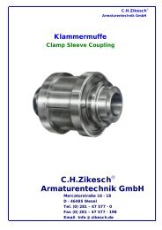
Klammermuffe<br />
Clamp Sleeve Coupling<br />
C.H.<strong>Zikesch</strong> ®<br />
<strong>Armaturentechnik</strong> <strong>GmbH</strong><br />
C.H.<strong>Zikesch</strong> ®<br />
<strong>Armaturentechnik</strong> <strong>GmbH</strong><br />
Mercatorstraße 16 - 18<br />
D - 46485 Wesel<br />
Tel. (0) 281 – 47 577 - 0<br />
Fax (0) 281 – 47 577 - 198<br />
Email Info @ zikesch.de
Klammermuffe<br />
C.H.<strong>Zikesch</strong> ®<br />
<strong>Armaturentechnik</strong> <strong>GmbH</strong><br />
Beschreibung<br />
Die ZIKES<strong>CH</strong> - Klammermuffe ist eine leicht lösbare Hochdruck - Rohrverbindung für höchste Drücke und<br />
Temperaturen. Die Konstruktion ist einfach und übersichtlich, der Wärmeausgleich in den einzelnen<br />
Bauteilen ist sehr günstig. Daher treten kaum unkontrollierbare Spannungen in den einzelnen Bauteilen auf.<br />
Die festigkeitsmäßige Beanspruchung der einzelnen Teile ist sehr niedrig, und deshalb können kleinste<br />
der einzelnen Teile ist sehr niedrig, und deshalb können kleinste Baumaße erzielt werden.<br />
Die ZIKES<strong>CH</strong> – Klammermuffe findet dort günstige Verwendung, wo bei hohen Drücken lösbare<br />
Verbindungen erwünscht sind, wie z. B. zum Anschluss von Rohrleitungen an Pumpen und Turbinen,<br />
zum Anschluss an Apparate, Überhitzer, Armaturen, zum Einbau von Messscheiben und Venturirohren usw.<br />
Ein wichtiges Verwendungsgebiet ist die Verbindung von Rohren aus Werkstoffen mit unterschiedlichen<br />
Wärmeausdehnungs-Koeffizienten, z. B. von austenitischen - ferritischen Rohrverbindungen, desgl. bei<br />
Schweißschwierigkeiten zweier verschiedener Werkstoffe.<br />
Eine ZIKES<strong>CH</strong> -Klammerverbindung besteht aus:<br />
1 Vorschweißstutzen mit Sägegewinde (1),<br />
1 Vorschweißstutzen mit Spannwulst (2),<br />
1 dreiteiligen Klammermuffe, bestehend aus 3 Klammersegmenten (3),<br />
2 konischen Spannringen (4),<br />
2 Membranschweißdichtungen oder Hülsringen (5),<br />
3 Sicherungslaschen oder Spannkloben (6).<br />
Clamp Sleeve Coupling<br />
Description<br />
The ZIKES<strong>CH</strong> Clamp Sleeve is an easily removable high-pressure pipe connection meeting highest<br />
pressure and temperatures. The design is simple and clear, the heat discipation of the components is most<br />
favourable. Therefore, any excessive stress of the parts is negligible. Due to proper selection of material<br />
strength of components minimizes stresses and thus minimum dimensions are achieved.<br />
The ZIKES<strong>CH</strong> Clamp Sleeve will find a useful application wherever for high-pressures, removable connections<br />
are desired; e. g., for piping installation for pumps and turbines, for the connections to vessels,<br />
super heaters, appliances, for Installation of measuring discs and venturi -tubes, etc. One of the most<br />
important field of application is for connections of piping with materials of different thermal-expansion<br />
coefficients, e. g., austenitic-ferritic pipe connections and similarily due to welding difficulties for<br />
connections of different materials.<br />
ZIKES<strong>CH</strong> Clamp Sleeve connection comprising:<br />
1 butt weld end with saw tooth threaded end (1)<br />
1 butt weld end with tension collar (2)<br />
1 three-part clamp sleeve comprising 3 clamp segments (3)<br />
2 conical tension rings (4)<br />
2 diaphragm-weld-rings or sleeve rings (5)<br />
3 butt straps or face plate jaws<br />
KLM-02
Aufbau, Bestandteile und Funktionsweise<br />
C.H.<strong>Zikesch</strong> ®<br />
<strong>Armaturentechnik</strong> <strong>GmbH</strong><br />
Alle Bauteile der Klammerverbindung sind Maschinenbauelemente, die mit großer Präzision und hohen<br />
Oberflächenqualitäten hergestellt sind. Die Werkstoffe der vorgenannten Bauelemente werden entsprechend<br />
den vorliegenden Betriebsbedingungen bzw. dem Rohrwerkstoff entsprechend festgelegt. Durch Verdrehen der<br />
aufgesetzten Klammersegmente wird Formschluß zwischen den Steilflanken des Sägegewindes und der Steilflanke<br />
des Wulststutzens erzeugt. Durch Aufziehen der konischen Spannringe auf die dreiteilige Klammermuffe<br />
wird ein radiales Verschieben der drei Klammersegmente zum Mittelpunkt hin erzeugt. Durch das radiale Gleiten<br />
der Steilflanken des Sägegewindes und der Steilfläche des Wulststutzens wird in Axialrichtung der Klammerverbindung<br />
ein sehr hoher Anpressdruck erzeugt, der die erforderliche Vorspannung und Abdichtung in der<br />
Verbindung herstellt.<br />
Kennzeichnung der Bauteile<br />
Alle Bauteile der Klammermuffe tragen die Werkstoff Kennzeichnung und bei vorgeschriebener amtlicher Ab-<br />
nahme den Abnahmestempel. Ebenfalls sind alle Teile mit der Auftragsnummer unseres Fertigungsauftrages<br />
gezeichnet. Die dreiteilige Klammermuffe (3) trägt auf der Stirnseite eine Ziffernbezeichnung, die einmal die<br />
Position der Klammermuffe bezeichnet (diese Nummer ist auf allen drei Klammersegmenten gleich) und außerdem<br />
eine Ziffernkennzeichnung in der Reihenfolge 1—3, die die Zusammenbaureihenfolge der drei Segmente festlegt.<br />
Bei dem Austenit -Ferrit-Verbindungen tragen außer den vorgenannten Bezeichnungen die Teile aus Ferrit einen<br />
Stempel „Ferrit“ und die austenitischen Teile einen Stempel „Austenit“. Beim Zusammenbau ist auf diese<br />
Kennzeichnung zu achten.<br />
Design, Components and Operation<br />
All components of the Clamp Sleeve are machine elements, produced with maximum precision and high<br />
quality surface finish. The materials of the above mentioned components are determined to meet<br />
the given operating conditions and or in accordance with piping material. By turning the clamp segments,<br />
clamping between the vertical flanks of the saw gear and the vertical flank of the reinforced socket is effect-<br />
ted. By tensioning the conical tension rings on the three part a radial shift clamp sleeve three segments<br />
towards the centre is produced.<br />
Due to radial sliding of the saw-tooth thread the mating-thread of the reinforced socket produces an<br />
extremely high pressure in axial direction of the sleeve, thus establishing the necessary initial tension and<br />
tightness within the connection.<br />
Marking Procedures on the Components<br />
D2<br />
L1<br />
Baulänge.<br />
D D1 D2<br />
All components of the Clamp bear material designation and the required Authority Acceptance Code stamp.<br />
Further, all parts are marked with the order number of our fabrication series. The three- part Clamp Sleeve (3)<br />
carry on its face the numbers which firstly describe Item-No. of the Clamp Sleeve (this number is the same on<br />
all 3 clamp segments) and, in addition, a reference numbers in sequences 1 to 3 which determine the sequen-<br />
ces of assembling the three segments. In the case of Austenitic-Ferrite connections, additionally the parts<br />
made from Ferrite bear a stamp ‚. Ferrite“ and those of austenitic mate- rial a stamp „Austenitic“. When<br />
assembling the com- ponents these markings should be carefully observed.<br />
KLM-03
C.H.<strong>Zikesch</strong> ®<br />
<strong>Armaturentechnik</strong> <strong>GmbH</strong><br />
Einspritzwasser – Regelventil Typ ESV<br />
Injection – Water Control Valve Typ ESV<br />
C.H.<strong>Zikesch</strong> ®<br />
<strong>Armaturentechnik</strong> <strong>GmbH</strong><br />
Mercatorstraße 16 - 18<br />
D - 46485 Wesel<br />
Tel. (0) 281 – 47 577 - 0<br />
Fax (0) 281 – 47 577 - 198<br />
Email Info @ zikesch.de
C.H.<strong>Zikesch</strong> ®<br />
<strong>Armaturentechnik</strong> <strong>GmbH</strong><br />
Einspritzwasser – Regelventil Typ ESV<br />
Injektion – Water Control Valve Type ESV<br />
ESV -02b
Einspritzwasser - Regelventil<br />
Vorzüge:<br />
- unkomplizierter Aufbau<br />
- problemlose Austauschbarkeit<br />
des Ventilsitzes<br />
- geringe Stellkräfte<br />
- wartungsarm<br />
- Betätigung durch alle üblichen<br />
Antriebsarten<br />
- kostengünstig<br />
- kurze Lieferzeit<br />
Verwendungszweck:<br />
Die Ventile dieser Baureihe haben die Aufgabe,<br />
das zur Heißdampf-Temperaturregelung dienende<br />
Einspritzwasser geregelt den nachgeschalteten<br />
Armaturen oder Kühlem zuzuführen.<br />
Um eine gute Anpassung der Armaturen an den<br />
vorliegenden Betriebsfall zu erreichen, sind die<br />
Einspritzventile in ein- oder mehrstufiger Ausführung<br />
lieferbar. Sie können jedoch auch als Regel- und Ab-<br />
sperrventile für andere Medien verwendet werden.<br />
Aufbau und Wirkungsweise:<br />
Der grundsätzliche Aufbau der Ventile kann dem<br />
nebenstehenden Schnittbild entnommen werden,<br />
welches ein Ventil in Einstufenausführung zeigt.<br />
Für Sonderfälle, d.h. sehr hohe Druckgefälle, ist<br />
die Armatur mit mehrstufigem Sitz/Kegel lieferbar.<br />
Das nachfolgende Schnittbild zeigt die Konstruktion<br />
eines vierstufigen Ventils.<br />
Ventil in Vierstufenausführung<br />
C.H.<strong>Zikesch</strong> ®<br />
<strong>Armaturentechnik</strong> <strong>GmbH</strong><br />
Hervorzuheben sind die stabile, gesenkgeschmiedete<br />
Ausführung des Ventilgehäuses,<br />
die verschleißfeste Konstruktion von Sitz und<br />
Kegel sowie die reibungsarme, nachziehbare<br />
Spindelabdichtung. Diese besteht, wie die<br />
Gehäusedichtung, aus Reingrafit. Gehäuse -<br />
und Sitzdichtung bilden gemeinsam eine im<br />
Krafthauptschluss liegende statische<br />
Doppeldichtung.<br />
Ventilkegel und -sitz werden im Werk<br />
dichtschließend eingeschliffen. Während des<br />
Betriebes werden diese Teile durch den am<br />
Gehäuseverschluß befindlichen Lochzylinder<br />
vor groben Fremdkörpern geschützt. Um auch<br />
feinere Verunreinigungen fernzuhalten,<br />
empfehlen wir den Einbau eines separaten<br />
Schmutzabscheiders vor der Armatur.<br />
Ventil in Einstufenausführung<br />
ESV-02
Injection Water Control Valve<br />
Advantages<br />
- Simple design<br />
- Easy exchaneability of valve seat<br />
- low actuating force<br />
- low maintenance efforts<br />
- Actuated by any common drive types<br />
- cost - effective<br />
- Short delivery period<br />
Application Range:<br />
Valves of this series feed injection water in a controlled<br />
way to the connected fittings and/or coolers. The injection<br />
water serves as a hot-steam temperature control.<br />
To achieve a good adaptation for each application, the<br />
injection valves are available as singlestage or multistage<br />
type. However, they can be used as control or stop valves<br />
for other media.<br />
Design and Function:<br />
A principle of the valve design is shown in the sketch to<br />
the right (singlestage valve type). In the case of special<br />
applications, i.e. very high pressure difference, the valve<br />
is available as a multistage seat/cone version. The sketch<br />
below shows the design of a four-stage valve.<br />
Four – stage valve type<br />
C.H.<strong>Zikesch</strong> ®<br />
<strong>Armaturentechnik</strong> <strong>GmbH</strong><br />
The stable and die-forged design of the valve<br />
casing, the wear-resistant construction of seat<br />
and cone, as well the low-friction spindle<br />
sealing which can be readjusted are features to<br />
be underlined. Together with the casing seal,<br />
also the spindle seal consists of pure graphite.<br />
Casing and seat seal form a static double<br />
sealing which is positioned in the main power<br />
connection.<br />
Valve cone and seat are ground-in during<br />
manufacturing. During operation, these parts<br />
are protected against coarsely foreign particles<br />
by a perforated cylinder which is installed in the<br />
casing cover. To protect the unit against fine<br />
particles, we recommend you to install a<br />
particle separator upstreams.<br />
Singlestage valve<br />
ESV-02e
Einspritzwasser - Regelventil<br />
Ventildaten:<br />
Technische Daten:<br />
C.H.<strong>Zikesch</strong> ®<br />
<strong>Armaturentechnik</strong> <strong>GmbH</strong><br />
Gehäuseform: Eck-, Z- oder Durchgangsform<br />
Nennweite: 15 – 125<br />
Druckstufen: bis PN 400<br />
zulässige<br />
Druckgefälle: Alle üblichen Druckgefälle, bei hohen<br />
Druckdifferenzen in mehrstufiger<br />
Ausführung<br />
Packungen: Nachziehbare Reingrafit-Spindel-<br />
Abdichtung, Gehäuse und Sitz-<br />
Dichtung ebenfalls aus Reingrafit<br />
Anschlüsse: Wahlweise Anschweißenden<br />
oder Flanschanschluß<br />
Werkstoffe: Gehäuse 1.5415<br />
Sitz 1.4057<br />
Spindel 1.4057<br />
Verschluß 1.4922/1.4903<br />
Abweichend von den beschriebenen<br />
Armaturenausführungen sind die<br />
Ventile auch in anderen Werkstoffen,<br />
für andere Medien und Einsatzbe-<br />
reiche zu verwenden.<br />
Antriebe: Pneumatisch. Hydraulisch,<br />
elektrisch über Dreh- oder Hebel-<br />
antrieb, Handrad,<br />
Baugröße I (bis PN 400) II (bis PN 400) III (bis PN 400)<br />
Nennweiten DN 15 – 50 25 – 80 65 – 125<br />
Kvs max. 11 max. 25 max.72<br />
Kennlinie Gleichprozentig, (auf Wunsch linear oder Quadratisch)<br />
Sitzdurchmesser: max.18 max.30 max.50<br />
Spindeldurchmesser 16 24 35<br />
Hub 20 25 35<br />
ESV-03
Injection Water Control Valve<br />
Valva data<br />
Technical Data<br />
C.H.<strong>Zikesch</strong> ®<br />
<strong>Armaturentechnik</strong> <strong>GmbH</strong><br />
Casing shape: Elbow, Z, or straight shape<br />
Nominal diameter: 15 – 125<br />
Pressure level: up to PN 400<br />
permissible<br />
pressure difference: all commonly used<br />
pressure differences,<br />
high pressure differences<br />
with multistage valve type<br />
Gland packings: readjustable pure graphite<br />
spindle sealing, seal for<br />
casing and seat also made<br />
of pure graphite<br />
Connections: optionally butt-weld ends or<br />
flange connection<br />
Materials: casing: 1.5415<br />
seat: 1.4057<br />
spindle: 1.4057<br />
cover: 1.4922/1.4903<br />
In addition to the fitting types<br />
described above, the valves<br />
can be used for other media,<br />
different applications, and<br />
made of other materials<br />
Drives:pneumatically, hydraulically, electrically with<br />
rotary or lever drive, handwheel<br />
Pressure stage I(up to PN 400) II (up to PN 400) III (up to PN 400)<br />
Nominal diameter DN 15 – 50 25 – 80 65 – 125<br />
Kvs max. 11 max. 25 max.72<br />
Characteristic equal percent, (optionally linear or square shaped)<br />
Seat diameter max.18 max.30 max.50<br />
Spindle diameter 16 24 35<br />
Stroke 20 25 35<br />
ESV-03e
Einspritzwasser-Regelventil<br />
Hauptabmessungen<br />
und<br />
Ausführungsbeispiele<br />
C.H.<strong>Zikesch</strong> ®<br />
<strong>Armaturentechnik</strong> <strong>GmbH</strong><br />
Größe NW Schenkelmaß Schenkelmaß Bauhöhe Durchmesser<br />
Eintritt Austritt Handrad<br />
I 15 – 50 150 175 450 250<br />
II 25 – 80 175 200 535 360<br />
III 65 – 125 250 250 725 450<br />
Sonderbaulängen und größere<br />
Nennweiten<br />
auf Anfrage.<br />
Durchgangsform<br />
ESV-04
Injection Water Control Valve<br />
Dimension<br />
and<br />
Design examples<br />
Elbow shape<br />
with<br />
electrical<br />
C.H.<strong>Zikesch</strong> ®<br />
<strong>Armaturentechnik</strong> <strong>GmbH</strong><br />
Size nominal leg size leg size overal diameter<br />
Inlet outlet height handwheel<br />
I 15 – 50 150 175 450 250<br />
II 25 – 80 175 200 535 360<br />
III 65 – 125 250 250 725 450<br />
Special lengths and larger nominal<br />
diameters on request.<br />
Straight shape is a special version.<br />
Z-shape with<br />
pneumatic<br />
drive<br />
Elbow shape<br />
With hydraulic<br />
drive<br />
Straight<br />
shape<br />
manually<br />
driven<br />
ESV-04e
C.H.<strong>Zikesch</strong> ®<br />
<strong>Armaturentechnik</strong> <strong>GmbH</strong><br />
Mindest-<br />
mengen-<br />
Ventil<br />
Typ MV und<br />
MVR<br />
Minimum<br />
Flow Valve<br />
Types<br />
MV and MVR<br />
C.H.<strong>Zikesch</strong> ®<br />
<strong>Armaturentechnik</strong> <strong>GmbH</strong><br />
Mercatorstraße 16 - 18<br />
D - 46485 Wesel<br />
Tel. (0) 281 – 47 577 - 0<br />
Fax (0) 281 – 47 577 - 198<br />
Email Info @ zikesch.de
C.H.<strong>Zikesch</strong> ®<br />
<strong>Armaturentechnik</strong> <strong>GmbH</strong><br />
Mindestmengen-Regelventil Typ MVR<br />
Minimum Control Valve Type MVR<br />
MV -02b
C.H.<strong>Zikesch</strong> ®<br />
<strong>Armaturentechnik</strong> <strong>GmbH</strong><br />
Mindestmengen-VentiI Typ MV<br />
Minimum Flow Valve Type MV<br />
Mindestmengen-Regelventil Typ MVR<br />
Minimum Control Valve Type MVR<br />
1. Verwendungszweck<br />
Bei in Betrieb befindlichen Hochdruck-Speise-<br />
pumpen darf eine bestimmte Fördermenge nicht<br />
unterschritten werden. Die Unterschreitung der<br />
sogenannten Mindestmenge hat zur Folge, dass<br />
sich das Speisewasser unzulässig erwärmt und<br />
aufgrund von Dampfbildung Kavitationsschäden<br />
auftreten. Wird bei der Kessel-Speisung die Min-<br />
destmenge unterschritten, so ist über eine By-<br />
pass Leitung die Differenz zur Mindestmenge<br />
abzuführen.<br />
Diese Aufgabe übernimmt das Mindestmengen-<br />
Ventil.<br />
Zweipunktregelung<br />
Stetige Regelung<br />
2. Regelung<br />
In der Praxis haben sich zwei Arten der Mindestmengenregelung<br />
durchgesetzt.<br />
Zweipunktregelung:<br />
Unterschreitet die Bedarfsmenge die Mindestmen-<br />
ge, so wird das Mindestmengen-Ventil voll geöffnet.<br />
Stetige Regelung:<br />
Unterschreitet die Bedarfsmenge die Mindestmen-<br />
ge, so wird das Mindestmengen-Ventil geregelt ge-<br />
öffnet. Bedarfsmenge plus abgeführte Mindestmen-<br />
ge ergeben die jeweils erforderliche Mindestmenge.<br />
Der Vorteil der Zweipunkt-Regelung liegt im einfach-<br />
en störungsunempfindlichen Aufbau. Ihr Einsatz ist<br />
bei kleinen bis mittleren Anlagen zweckmäßig.<br />
Bei großen Anlagen und bei Anlagen, die häufig an-<br />
und abgefahren werden, ist die stetige Regelung<br />
vorteilhafter, da sie größere Energieersparnisse ermöglicht.<br />
Bei drehzahlgeregelten Speisepumpen<br />
kann gleichzeitig die Mindestmenge der Drehzahl der<br />
Pumpe angepasst werden.<br />
Aus obenstehendem Schaltschema ist der<br />
grundsätzliche Aufbau einer Mindestmengenanlage<br />
zu entnehmen.<br />
Die Fördermenge wird mittels Blende oder Düse<br />
erfasst. Zur Kontaktgabe bei der Zweipunktregelung<br />
wird ein Wirkdruckwandler in Verbindung mit einer<br />
Schalteinrichtung eingesetzt, deren Grenzkontakte<br />
mittel- oder unmittelbar zum öffnen oder Schließen<br />
des Mindestmengen-Ventils eingesetzt werden.<br />
Sinngemäß erfolgt die Betätigung der Ventile durch<br />
stetige Regelung. Die Schalteinrichtung wird z. B.<br />
durch einen stetigen Regler ersetzt, dem bei Verwendung<br />
drehzahlgeregelter Pumpen die entsprechend<br />
variierende Führungsgröße ebenfalls aufgeschaltet<br />
werden kann. Je nach Größe der Bedarfs-<br />
Menge wird das Mindestmengen-Ventil ausgeregelt,<br />
so dass die gesamt erforderliche Mindestmenge nicht<br />
unterschritten wird.<br />
MV-02
3. Ventilaufbau und Wirkungsweise<br />
Der grundsätzliche Aufbau der Armaturen ist den<br />
Abbildungen zu entnehmen.<br />
Bild 1 - unten - zeigt ein Ventil Typ MV mit Auf-<br />
Zu- Charakteristik. Bild 2 - rechts zeigt ein Regel-<br />
Ventil Typ MVR.<br />
Die Drosselung des Speisewassers erfolgt im Ventil<br />
in mehreren Stufen. Beim Mindestmengen- Regel-<br />
ventil ist den Drosselkörpern der Regelkegel vorge-<br />
schaltet. Durch Formgebung und entsprechende Ab-<br />
stufung des Gesamtgefälles auf die einzelnen Dros-<br />
seln werden Geräuschbildung und Kavitation sicher<br />
beherrscht. Starker Beanspruchung unterliegende<br />
Teile sind aus entsprechend widerstandsfähigem<br />
Werkstoff gefertigt. Durch zweckmäßigen Aufbau<br />
des Ventils sind Verschleißteile leicht auswechselbar.<br />
C.H.<strong>Zikesch</strong> ®<br />
<strong>Armaturentechnik</strong> <strong>GmbH</strong><br />
4. Technische Daten<br />
Gehäusewerkstoff: 15M03 (1.5415) Sonder-<br />
ausführungen<br />
Anschlüsse: auf Wunsch Schweißenden<br />
oder Flansche<br />
Garnitur: korrosionsbeständiger Stahl<br />
Antriebsarten: Drehfeldmagnet mit Zwischen-<br />
getriebe, elektromagnetischer<br />
Stellantrieb, hydraulischer,<br />
pneumatischer Antrieb<br />
MV-03
3. Valve construction and operation<br />
The basic construction of the fittings is shown<br />
in the illustrations.<br />
Illustration 1 - below - shows a Valve Type MV with<br />
On-Off characteristic.<br />
Illustration 2 - on the right - shows a Control Valve<br />
Type MVR.<br />
The throttling of the feed water is effected in several<br />
stages. The minimum flow valve features a control-<br />
cone fitted upstream of the throttling device. Through<br />
suitable shaping and corresponding stepping of the<br />
total pressure on the individual throttles, noise and<br />
cavitation are controlled. Elements prone to severe<br />
duty are made of resistant material. Through a practical<br />
design of the valve, wear parts are easily replaceable.<br />
C.H.<strong>Zikesch</strong> ®<br />
<strong>Armaturentechnik</strong> <strong>GmbH</strong><br />
4.Technical Data:<br />
Casing material: 15 Mo 3 (Mat.No. 1.5415), special<br />
equipment<br />
Connections: if desired welding connections<br />
or flanges, material according<br />
to specification<br />
Fittings: Corrosion-resistant steel,<br />
Actuator types: electro-magnetic field with intermediate<br />
gear, electro-magnetic<br />
drive, hydraulic, pneumatic drive.<br />
MV-06
Minimum Flow Valve Type MV<br />
Minimum Control Valve Type MVR<br />
1.) Application<br />
In HP-Feed pump Operation fixed flow must b<br />
ascertained. Throughput below this fixed minimum<br />
flow causes overheating of the feed water, cones-<br />
quently formation of steam may result in cavitation<br />
damage. If the boiler feed falls below the minimum<br />
flow, the differential flow must be discharged through<br />
bypass-line which is accomplished via the minimum<br />
flow valve.<br />
two – step control<br />
Permanent control<br />
C.H.<strong>Zikesch</strong> ®<br />
<strong>Armaturentechnik</strong> <strong>GmbH</strong><br />
In practice two types of minimum flow control valves<br />
have proven successful.<br />
Two-step control:<br />
lf the flow required falls below the minimum flow, the<br />
minimum flow valve opens fully.<br />
Permanent control:<br />
lf the flow required falls below the minimum flow, the<br />
minimum flow valve opens controlled. Flow required<br />
plus discharged minimum flow equals the<br />
corresponding necessary minimum flow.<br />
The advantage of the two-step control is based on<br />
the simple interruption-free construction. lt can be<br />
properly used for operations in small and medium<br />
sized plants. The permanent control is more profit<br />
able, as it saves more energy for large-sized plants<br />
and for plants being often started and stopped.<br />
For speed-governed feed pumps operation the mini-<br />
mum flow can be adjusted to the rpm of the pump.<br />
The basic construction of a minimum flow plant can<br />
be seen on the above drawing.<br />
The volumetric delivery is obtained via an orifice<br />
plate or a nozzle. The switching equipment signals<br />
a contact-impulse to the two-step control via a pressure-drop<br />
variator. The limit contacts of which are<br />
operated directly or indirectly for opening and closing<br />
of the minimum flow valve.<br />
Similarly the valves are operated by permanent control.<br />
For example, the switching equipment is<br />
replaced by a permanent controller that can also be<br />
locked in to the corresponding variable-command of<br />
the applied rpm-controlled pumps. The minimum<br />
flow valve is controlled according to the minimum<br />
flow of the required throughout, so that the total<br />
necessary minimum flow does not fall below the set<br />
limit.<br />
MV-05<br />
MV-02
5. Ausführungsbeispiele<br />
5. Application examples<br />
C.H.<strong>Zikesch</strong> ®<br />
<strong>Armaturentechnik</strong> <strong>GmbH</strong><br />
Mindestmengenventil Mindestmengenventil Mindestmengenventil Mindestmengenventil<br />
mit Stellzylinder und mit E – Antrieb mit direkt aufgebautem mit Drehfeldmagnet<br />
Öffnungsfeder hydr. Stellantrieb und Öffnungsfeder<br />
Mindestmengenventil Mindestmengenventil<br />
mit pneumat. Antrieb mit hydr. Zylinder<br />
Minimum flow valve Minimum flow valve Minimum Flow valve Minimum flow valve<br />
with positioning cylinder with electric actuator with directly built-on with elektro-magnetic,<br />
and opening spring hydraulic actuator electric – actuator and<br />
opening spring<br />
Minimum flow valve Minimum flow valve<br />
with pneumatic actuator with hydraulic cylinder<br />
MV-04
Drossel-<br />
C.H.<strong>Zikesch</strong> ®<br />
<strong>Armaturentechnik</strong> <strong>GmbH</strong><br />
strecken<br />
Throttling sections<br />
Typ<br />
MVD<br />
Type<br />
MVD<br />
C.H.<strong>Zikesch</strong> ®<br />
<strong>Armaturentechnik</strong> <strong>GmbH</strong><br />
Mercatorstraße 16 - 18<br />
D - 46485 Wesel<br />
Tel. (0) 281 – 47 577 - 0<br />
Fax (0) 281 – 47 577 - 198<br />
Email Info @ zikesch.de
C.H.<strong>Zikesch</strong> ®<br />
<strong>Armaturentechnik</strong> <strong>GmbH</strong><br />
MVD-02
C.H.<strong>Zikesch</strong> ®<br />
<strong>Armaturentechnik</strong> <strong>GmbH</strong><br />
MVD-03
C.H.<strong>Zikesch</strong> ®<br />
<strong>Armaturentechnik</strong> <strong>GmbH</strong><br />
Throttling sections Type MVD<br />
MVD-04
C.H.<strong>Zikesch</strong> ®<br />
<strong>Armaturentechnik</strong> <strong>GmbH</strong><br />
Wasser – Regelventil Typ RVW<br />
Water regulating Valve Typ RVW<br />
C.H.<strong>Zikesch</strong> ®<br />
<strong>Armaturentechnik</strong> <strong>GmbH</strong><br />
Mercatorstraße 16 - 18<br />
D - 46485 Wesel<br />
Tel. (0) 281 – 47 577 - 0<br />
Fax (0) 281 – 47 577 - 198<br />
Email Info @ zikesch.de
Wasser-Regelventil RVW<br />
C.H.<strong>Zikesch</strong> ®<br />
<strong>Armaturentechnik</strong> <strong>GmbH</strong><br />
Baureihe RVW in Schmiedestahlausführung für höchste Drücke<br />
und Durchsatzmengen<br />
1. Verwendungszweck<br />
Die hier vorgestellte Baureihe RVW ist für höchste Drücke, höchste Temperaturen und Leistungen einsetzbar.<br />
Wasserregelventile RVW werden in allen Industriezweigen verwendet, bei denen Wasser auf einen niederen<br />
Druck entspannt werden soll. Die Armatur ist ein Druckreduzierventil.<br />
2. Aufbau und Wirkungsweise<br />
Das Ventilgehäuse mit seinem seitlichen Eintrittsstutzen nimmt den fest eingeschweißten, jedoch austauschbaren,<br />
Sitz und den anschließenden Erweiterungskonus auf.<br />
Die Ventilspindel ist mit dem Kegel aus einem Stück gefertigt. Geführt über ein Lager im Ventildeckel und einem<br />
zweiten Lager im Ventileinsatz ist die Spindel schwingungsfrei gelagert. Aufsatz und Ventil sind miteinander durch<br />
eine montagefreundliche Klemmverbindung befestigt. Durch bestimmte innere Formgebung lässt sich der<br />
Geräuschpegel niedrig halten.<br />
Der von der Regeleinrichtung gegebene Impuls bewirkt über den Ventilantrieb eine Stellungsänderung des<br />
Ventilkegels.<br />
Der freigegebene Spalt zwischen Sitz und Kegel lässt das Medium hindurchfließen. Das Ventil öffnet das<br />
Medium, dichtet daher in geschlossenem Zustand vollkommen ab.<br />
Water Regulating Valve RVW<br />
RVW series in forged steel for the highest pressures and<br />
throughputs<br />
Kennlinie – Characteristic for cones<br />
1. Application<br />
The RVW series presented here is suitable for use under conditions<br />
Of the highest pressures, temperatures and outputs.<br />
RVW water regulating valves are used in all branches of industry<br />
where water pressures have to be reduced.<br />
The device is effectively a pressure reducing valve.<br />
2. Design and mode of operation<br />
The valve body has a lateral inlet connection and is fitted with a seat which is welded in place but which can<br />
be exchanged, and the dose fitting expansion cone. The valve spindle and the cone are made in one piece.<br />
The spindle is mounted so as to be free from vibration and is guided in a bush in the valve cover and a second<br />
bush in the valve core. The cover and the valve are fastened together by a clamping device which facilitates<br />
assembly. The noise level is kept low by the special design of the internal passages. The pulse from the control<br />
unit causes the valve drive to change the position of the valve cone. The gap between the seat and the cone<br />
allows the medium to flow. The valve opens against the pressure of the medium and therefore effects a complete<br />
seal in the closed condition.<br />
Vorzüge: Unkomplizierter Aufbau bei erstklassiger Bearbeitung gewährleisten einen<br />
einwandfreien Betrieb. Durch Baukastensystem ergibt sich ein günstiger Preis und<br />
kurze Lieferzeit. Betätigungsmöglichkeiten durch viele Antriebsarten.<br />
Advantages:<br />
Simple, rugged construction and first dass manufacture ensure trouble-free<br />
operation.<br />
Reasonable price and short delivery times are achieved by modular<br />
construction. Many types of drive can be adopted for operating the valves.<br />
RVW-02
C.H.<strong>Zikesch</strong> ®<br />
<strong>Armaturentechnik</strong> <strong>GmbH</strong><br />
RVW-03
C.H.<strong>Zikesch</strong> ®<br />
<strong>Armaturentechnik</strong> <strong>GmbH</strong><br />
Dampf – Regelventil Typ RVD<br />
Steam Control Valve Typ RVD<br />
C.H.<strong>Zikesch</strong> ®<br />
<strong>Armaturentechnik</strong> <strong>GmbH</strong><br />
Mercatorstraße 16 - 18<br />
D - 46485 Wesel<br />
Tel. (0) 281 – 47 577 - 0<br />
Fax (0) 281 – 47 577 - 198<br />
Email Info @ zikesch.de
Dampf-Regelventil RVD<br />
C.H.<strong>Zikesch</strong> ®<br />
<strong>Armaturentechnik</strong> <strong>GmbH</strong><br />
Baureihe RVD in Schmiedestahlausführung für höchste<br />
Drücke und Temperaturen<br />
1. Verwendungszweck<br />
Die hier vorgestellte Baureihe RVD ist für höchste Drücke, höchste Temperaturen und Leistungen einsetzbar.<br />
Dampfregelventile RVD`s werden in allen Industriezweigen verwendet, bei denen Dampf auf einen niederen<br />
Druck entspannt werden soll. Die Armatur ist ein Druckreduzierventil.<br />
2. Aufbau und Wirkungsweise<br />
Das Ventilgehäuse mit seinem seitlichen Eintrittsstutzen nimmt den fest eingeschweißten, jedoch austauschbaren,<br />
Sitz und den anschließenden Erweiterungskonus auf.<br />
Die Ventilspindel ist mit dem Kegel aus einem Stück gefertigt. Geführt über ein Lager im Ventildeckel und einem<br />
zweiten Lager im Ventileinsatz ist die Spindel schwingungsfrei gelagert. Aufsatz und Ventil sind miteinander durch<br />
eine montagefreundliche Klemmverbindung befestigt. Durch bestimmte innere Formgebung und durch eventuellen<br />
Einbau einer oder mehrerer Lochscheiben lässt sich der Geräuschpegel niedrig halten. Der von der<br />
Regeleinrichtung gegebene Impuls bewirkt über den Ventilantrieb eine Stellungsänderung des Ventilkegels.<br />
Der freigegebene Spalt zwischen Sitz und Kegel lässt das Medium hindurchfließen. Das Ventil öffnet gegen das<br />
Medium, dichtet daher in geschlossenem Zustand vollkommen ab.<br />
Steam control Valve RVD<br />
Fabrication program RVD in forged<br />
Steel for highest pressures and<br />
Temperatures.<br />
1. Application<br />
The program RVD introduced here can be applied for highest<br />
Pressures, highest temperatures an capacities.<br />
Steam control valves are used as pressure reducing valves in all<br />
types of the industry where steam required is flashed at lower<br />
pressures<br />
2. Design and mode of operation<br />
The valve body has horizontal inlet connections firmly welded, whereas the seat and the joined conical widening<br />
are removable. The valve spindle and the cone are made in one piece.<br />
The valve spindle with its plug is fabricated in one piece. The spindle is pivoted vibration- free, between a bush in<br />
the valve cover and a second bush in the valve seat. The cover and the valve are fastened together by a clamping<br />
device which facilitates assembly. The noise level is kept low by the special design of the internal passages. The<br />
pulse from the control<br />
unit causes the valve drive to change the position of the valve cone. The gap between the seat and the cone<br />
allows the medium to flow. The valve opens against the pressure of the medium and therefore effects a complete<br />
seal in the closed condition.<br />
Vorzüge: Unkomplizierter Aufbau bei erstklassiger Bearbeitung gewährleisten einen<br />
einwandfreien Betrieb. Durch Baukastensystem ergibt sich ein günstiger Preis und<br />
kurze Lieferzeit. Betätigungsmöglichkeiten durch viele Antriebsarten.<br />
Advantages:<br />
Simple, rugged construction and first dass manufacture ensure trouble-free<br />
operation.<br />
Reasonable price and short delivery times are achieved by modular<br />
construction. Many types of drive can be adopted for operating the valves.<br />
RVD-02
C.H.<strong>Zikesch</strong> ®<br />
<strong>Armaturentechnik</strong> <strong>GmbH</strong><br />
RVD-3
C.H.<strong>Zikesch</strong> ®<br />
<strong>Armaturentechnik</strong> <strong>GmbH</strong><br />
Dampfzustands – Regelventil<br />
Typ Dze<br />
Steam condition regulating valve<br />
Typ Dze<br />
C.H.<strong>Zikesch</strong> ®<br />
<strong>Armaturentechnik</strong> <strong>GmbH</strong><br />
Mercatorstraße 16 - 18<br />
D - 46485 Wesel<br />
Tel. (0) 281 – 47 577 - 0<br />
Fax (0) 281 – 47 577 - 198<br />
Email Info @ zikesch.de
Dampfzustands – Regelventil<br />
Steam condition regulating valve<br />
C.H.<strong>Zikesch</strong> ®<br />
<strong>Armaturentechnik</strong> <strong>GmbH</strong><br />
DZE -02b
Dampfzustands – Regelventil Dze<br />
Steam condition regulating valve Dze<br />
1.Verwendungszweck<br />
C.H.<strong>Zikesch</strong> ®<br />
<strong>Armaturentechnik</strong> <strong>GmbH</strong><br />
Die hier vorgestellte Baureihe DZe ist für höchste Drücke und Temperaturen einsetzbar.<br />
Dampfzustands-Regelventile DZe werden in allen Industriezweigen verwendet, bei denen Dampf auf<br />
einen niedrigeren Druck entspannt und gleichzeitig gekühlt werden muss. Beide Aufgaben<br />
werden ohne Nachschalten eines Kühlers vom DZe übernommen. Sein Einsatz ist deshalb besonders<br />
interessant in Kraftwerken, Dampfverteilungsnetzen der chemischen Industrie sowie in Papier- und Zuckerfa-<br />
briken u. a.<br />
2. Aufbau und Wirkungsweise<br />
Das Dampfzustands - Regelventil DZe drosselt und kühlt Heißdampf in einem Ventilgehäuse. Der Betrieb<br />
dieses Ventiles ist unkompliziert, der Raumbedarf ist sehr gering, die Wirtschaftlichkeit dieses Umformventil`s ist<br />
infolge seines geringen Platzbedarfs gut.<br />
Das Dampfzustands-Regelventil findet Verwendung für jeden praktisch verfügbaren Dampfzustand höchster<br />
Drücke und höchster Temperaturen bis herunter zu den niedrigsten Anfangswerten. Durchsatzmengen für das<br />
Ventil sind unbeschränkt.<br />
Sorgfältige Beobachtungen im Betrieb haben es uns ermöglicht, durch innere Formgebung, durch<br />
kompakte Bauform und durch den Einbau eines oder mehrerer Lochkegel den Geräuschpegel gering zu halten.<br />
1.Application<br />
The DZe series presented here is suitable for conditions of the highest pressures and temperatures.<br />
Steam condition regulating valves of type DZe are used in all branches of industry where steam has to be<br />
simultaneously expanded to a lower pressure and cooled. The DZe carried out both duties without the<br />
need to install a cooler. For this reason its use is particularly attractive in power stations, steam distribution<br />
mains in the chemical industry and in paper mills and sugar factories etc.<br />
2.Design and mode of operation<br />
The steam condition regulating valve throttles and cools superheated steam in a single valve body. The<br />
operation of this valve is straightforward. lt occupies very little space and is extremely economical due to<br />
its compactness and relatively low initial cost. The steam condition regulating valve can be applied to<br />
practically any available steam condition from the highest pressures and temperatures right down to the<br />
lowest initial values. Throughput rates for the valves are unlimited. The coolant is not supplied directly<br />
into the steam flow, but is injected through a central hole in the valve spindle. When the valve is opened,<br />
a relatively smaller flow from the main steam supply automatically enters an annular chamber in the<br />
regulating cone and atomises the centrally supplied coolant immediately it leaves the regulating cone.<br />
The auxiliary steam flow immediately heats the coolant approximately to evaporation temperature.<br />
Even under conditions of partial bad this ensures thorough mixing.<br />
Dze2
C.H.<strong>Zikesch</strong> ®<br />
<strong>Armaturentechnik</strong> <strong>GmbH</strong><br />
DZe-03
Vorwärmer-<br />
C.H.<strong>Zikesch</strong> ®<br />
<strong>Armaturentechnik</strong> <strong>GmbH</strong><br />
Absicherungen<br />
Preheater protection<br />
C.H.<strong>Zikesch</strong> ®<br />
<strong>Armaturentechnik</strong> <strong>GmbH</strong><br />
Mercatorstraße 16 - 18<br />
D - 46485 Wesel<br />
Tel. (0) 281 – 47 577 - 0<br />
Fax (0) 281 – 47 577 - 198<br />
Email Info @ zikesch.de<br />
Technik für die Zukunft – Qualität aus Tradition – Service Tag und Nacht<br />
Technology for the future – Quality by tradition – Service 24 hours a day
Umschaltventil Typ UV<br />
Cange–over valve Type UV<br />
C.H.<strong>Zikesch</strong> ®<br />
<strong>Armaturentechnik</strong> <strong>GmbH</strong><br />
VW -06b
Vorwärmerabsicherungen<br />
Preheater protection units<br />
C.H.<strong>Zikesch</strong> ®<br />
<strong>Armaturentechnik</strong> <strong>GmbH</strong><br />
VW-01-1
Vorwärmerabsicherungen<br />
Preheater protection units<br />
®<br />
C.H.<strong>Zikesch</strong><br />
<strong>Armaturentechnik</strong> <strong>GmbH</strong><br />
1.1 Verwendungszweck<br />
Um den Wirkungsgrad einer Dampfkesselanlage zu erhöhen, wird das vom Speisewasserbehälter zum<br />
Kessel strömende Speisewasser durch einen Vorwärmer beheizt. Der Vorwärmer ist ein Wärmetauscher,<br />
durch dessen Rohre das Speisewasser strömt. Von außen werden die Rohre mit Abzapfdampf von der<br />
Turbine beaufschlagt.<br />
Bei einem evtl. Leck im Rohrsystem strömt Wasser mit höherem Druck in den Dampfraum mit niederem<br />
Druck. Um jetzt Schäden zu vermeiden, und zwar durch<br />
a) Eindringen von Speisewasser in die Turbine<br />
b) Aufbau eines unzulässigen Druckes im Vorwärmermantel<br />
muss der Vorwärmer schnellstens von der Speisewasserdruckleitung getrennt werden. Dieses erfolgt durch<br />
eine Vorwärmerabsicherung, d. h. durch am Ein- und Austritt des Vorwärmers angeordnete, eigenmedium-<br />
gesteuerte Schnellschlußarmaturen. Hierbei wird normalerweise am Eintritt eine Umschaltarmatur und am<br />
Austritt eine Absperrarmatur angeordnet.<br />
2.1 Aufbau und Wirkungsweise<br />
Die nachfolgend gezeigten Schaltschemata geben einige Anordnungen und deren Steuerorgane wieder.<br />
Die Schaltschemata zeigen die Armaturen in normaler Arbeitsstellung, bei geöffnetem Vorwärmerstrang und<br />
gesperrter Bypassleitung. Zu allen Schaltschemata gilt folgende Wirkungsweise:<br />
2.1.1 Funktion beim automatischen Umschalten auf Bypass<br />
Der Niveauwächter (6) gibt einen elektrischen Impuls auf das Steuerventil (3), welches die Entlastungsleitung<br />
frei gibt. Der Druck unter dem Steuerkolben der Hauptventile wird abgebaut. Das Umschaltventil und das<br />
Schnellschlußventil schalten durch die Differenzdruckkraft am Kolben um. Die Verbindungsbohrung im<br />
Verschlußpilz bewirkt den Druckausgleich zwischen dem Raum über dem Steuerkolben und der<br />
Speisewasserleitung. Durch die Drosselventile (4) kann die Umschaltgeschwindigkeit eingestellt werden.<br />
Danach Blockierung der beiden Hauptventile durch Niederschrauben der Gewindespindel. Die Blockierspin-<br />
deln bewirken durch ihr Niederschrauben eine Erhöhung der Dichtkraft an den Absperrsitzen.<br />
1.1 Application<br />
To improve the efficiency of a steam vessel system, feed-water, flowing from the feed-water tank to the<br />
vessel, is heated by a preheater. The preheater is a heat exchanger with tubes containing feed-water. From<br />
the outside, the tubes receive steam drawn-off from the turbine.<br />
In the case of a leakage in the tubing system, water of higher pressure rushes into the vapor room of lower<br />
pressure. To avoid any damages by<br />
a) penetration of feed-water into the turbine<br />
b) build-up of inadmissible pressure in the preheater jacket,<br />
the preheater must be separated from the feed-water pressure tube as soon as possible. This will be provided<br />
by the preheater protection unit, i.e. by quick closing valves which are controlled by their own medium and<br />
located at the in- and outlet of the preheater. Normally a change-over valve is located at the inlet and a stop<br />
valve at the outlet.<br />
2.1 Construction and function<br />
The following circuit diagrams show some arrangements together with their control units.<br />
The circuit diagrams show the valves in normal working position with opened preheater pipe train and locked<br />
bypass tube.<br />
All circuit diagrams have the following functions:<br />
2.1.1 Function with automatic switch-over to bypass<br />
The level sensor (6) feeds an electrical pulse to the control valve (3) which opens the relief tube. Pressure<br />
under the control piston of the main valves is reduced. Because of the pressure difference, the change-over<br />
and the quick stop valves shift at the piston. The interconnecting bore in the sealing plug provides for the<br />
pressure compensation between the space above the control piston and the feed-water tube. The switching<br />
speed can be adjusted by the Flow control valves (4). Subsequently both valves are blocked through the<br />
screwed down threaded spindle. An increase of the tightening force on the blocking spindles improves the<br />
sealing at the valve seats.<br />
VW-02
Vorwärmerabsicherungen<br />
Preheater protection units<br />
®<br />
C.H.<strong>Zikesch</strong><br />
<strong>Armaturentechnik</strong> <strong>GmbH</strong><br />
Ein Zuhalten der Absperrkegel gegen den vollen Speisewasserdruck ist nicht möglich, die Blockierspin-<br />
deln würden ausknicken. Nach dem Umschaltvorgang sind die Steuerventile zu schließen. Die nach dem<br />
Schließen der Steuerventile auftretende Spindelauftriebskraft kann von den Blockierspindeln aufgenommen<br />
werden.<br />
2.1.2 Rückstellen der beiden Haupt-Ventile auf<br />
Normalbetrieb<br />
Die Blockierspindeln beider Haupt-Ventile bis in Stellung „Vorwärmerstrang auf“ drehen. Der Vorwärmer<br />
ist über Absperrventile (5) zu füllen und auf Betriebsdruck zu bringen. Bei einem Innendruck von mind.<br />
50 bar Druckausgleich an allen Stellen, schalten die Ventile um. Bei kleineren gewünschten Umschalt-<br />
drücken ist der Umschalt druck anzugeben. Bei sehr kleinen Umschaltdrücken ist zusätzlich der obere<br />
Steuerkolbenraum durch Öffnen eines weiteren Ventils zu entlasten.<br />
Infolge des wirksamen Spindelauftriebes in der Stellung „Vorwärmer auf“, und ggf. durch Entlastung des<br />
oberen Kolbenraumes, schalten die Vorwärmerabsicherungsventile um. Zur Herstellung der Betriebsbe-<br />
reitschaft sind dann noch die Absperrventile (5) zu schließen.<br />
Die Steckkupplung dient lediglich zur Verstellung der Ventile in drucklosem Zustand durch das Hand-<br />
rad. Hierbei muss das Absperrventil in jedem Falle geöffnet sein. Die Steckkupplung ist nach Betäti-<br />
gung sofort abzuziehen. Die Absperrfüllventile (5) dienen nur zum Auffüllen des Vorwärmers und sind<br />
danach immer zu schließen.<br />
3.1 Aufbau und Wirkungsweise<br />
Die nachfolgend gezeigten Schaltschemata geben einige Anordnungen und deren Steuerorgane wieder.<br />
Die Schaltschemata zeigen die Armaturen in normaler Arbeitsstellung, bei geöffnetem Vorwärmerstrang<br />
und gesperrter Bypassleitung.<br />
Keeping the stop cones closed against the full feed-water pressure is impossible, the blocking spindles would<br />
buckle. After the shifting process, the control valves must be closed. The spindle lifting force after closure of<br />
the control valves can be taken up by the locking spindles.<br />
2.1.2 Resetting the two main valves to standard position<br />
Rotate the locking spindles of the two main valves up to position 'Preheater pipe train open'. Fill the preheater<br />
through the stop valves (5) up to working pressure. At an internal pressure of min. 50 bars pressure<br />
compensation at any position, the valves will shift over. If you want the valves to shift at lower pressure, you<br />
must indicate the pressure. With very low shifting pressures must the upper control piston space be relieved<br />
by opening another valve. Due to the current spindle lifting force in position 'preheater open' and should it be<br />
necessary to relief the upper piston space, the preheater protection valves shift. To revert to normal<br />
operation, you must shut the stop valves (5).<br />
The plug coupling is only used for adjusting the valves with the hand wheel in unpressurerized condition. In<br />
this case, the stop valve must always be closed. Pull-off the plug coupling immediately after use. The stop<br />
valves (5) are used for filling the preheater – always close them after filling the preheater.<br />
3.1 Construction and function<br />
The following circuit diagrams show some arrangements with their control units.<br />
The circuit diagrams show the valves in standard working position with opened preheater pipe train and<br />
locked bypass tube.<br />
VW-03
C.H.<strong>Zikesch</strong> ®<br />
<strong>Armaturentechnik</strong> <strong>GmbH</strong><br />
Vorwärmerabsicherungen: Schaltschema 1<br />
Preheater protection units, circuit diagram 1<br />
Funktion beim automatischen Umschalten auf Bypass:<br />
Das Magnetsteuerventil (3) erhält vom Niveauwächter (6) einen elektrischen Impuls und gibt die Impuls-<br />
leitung frei. Der Druck unter dem Steuerkolben der Hauptventile baut ab und Umschaltventil (1) und<br />
Schnellschlußventil (2) schalten um. Die Entlastungsbohrung im Gehäuseverschluß bewirkt den Druck-<br />
ausgleich zwischen dem Raum über dem Steuerkolben und der Speisewasserleitung.<br />
Durch die Drosselventile (4) werden die Umschaltgeschwindigkeiten eingestellt. Die Blockierung der beiden<br />
Ventile geschieht durch das Niederschrauben der Gewindespindel.<br />
1 Umschaltventil<br />
2 Schnellschlußventil<br />
3 Magnetsteuerventil<br />
4 Drosselventile<br />
5 Füllventile<br />
6 Niveauwächter<br />
Function during automatic shifting to bypass.<br />
The solenoid control valve (3) receives an electrical pulse from the level sensor (6) and releases the pulse<br />
tube. The pressure below the control piston of the main valves decreases, and both, the change-over<br />
valve (1) and the quick stop valve (2) shift. The compensation bore in the casing closure serves to compen-<br />
sate the pressure between the space above the control piston and the feed-water tube.<br />
The shifting speeds are set by the flow control valves (4). Blocking the two valves is carried out by screwing-<br />
down the threaded spindles.<br />
1 Change-over valve<br />
2 Quick stop valve<br />
3 Solenoid control valve<br />
4 Flow control valve<br />
5 Filling valves<br />
6 Level sensor<br />
VW-04
C.H.<strong>Zikesch</strong> ®<br />
<strong>Armaturentechnik</strong> <strong>GmbH</strong><br />
Vorwärmerabsicherungen: Schaltschema 2<br />
Preheater protection units, circuit diagram 2<br />
Vorwärmer einsträngig, Steuerung durch Steuerventil mit Elektroantrieb<br />
Das Steuerventil mit elektromotorischem Antrieb (3) erhält vom Niveauwächter einen elektrischen<br />
Impuls und gibt die Impulsleitung frei. Der Druck unter dem Steuerkolben der beiden Hauptventile<br />
baut sich ab und Umschaltventil (1) und Schnellschlußventil (2) schalten um. Durch die Drossel-<br />
ventile (4) kann die Umschaltgeschwindigkeit beider Hauptarmaturen einzeln eingestellt werden.<br />
Die Blockierung der beiden Ventile in Bypass-Stellung geschieht durch Niederschrauben der Ge-<br />
windespindel.<br />
1 Umschaltventil<br />
2 Schnellschlußventil<br />
3 Steuerventil mit Elektroantrieb<br />
4 Drosselventile<br />
5 Füllventile<br />
6 Niveauwächter<br />
Single-strand preheater<br />
Control by control valve with electric drive<br />
The control valve with electric drive (3) receives an electrical pulse from the level sensor and opens the<br />
pulse tube. The pressure below the control piston of the two main valves decreases, and both, the<br />
change over valve (1) and the quick stop valve (2) shift. The shifting speed of the two main valves can be<br />
set individually by the flow control valves (4). Blocking the two valves in bypass-position is carried out by<br />
screwing-down the threaded spindle.<br />
1 Change-over valve<br />
2 Quick stop valve<br />
3 Control valve with electric drive<br />
4 Flow control valves<br />
5 Filling valves<br />
6 Level sensor<br />
VW-05
Umschaltventil UV C.H.<strong>Zikesch</strong> ®<br />
Change – over valve UV <strong>Armaturentechnik</strong> <strong>GmbH</strong><br />
Die Hauptarmaturen innerhalb der Absicherung sind die Umschaltventile UV. Die Abbildung zeigt das<br />
Umschaltventil in Arbeitsstellung. Der Weg von der Pumpe zum Vorwärmer ist freigegeben, die Bypassleitung<br />
dagegen abgesperrt. Die Steckkupplung (14) ist entfernt und das Steuerventil geschlossen. Über und<br />
unter dem Kolben (5) herrscht bei dieser Stellung gleicher Druck.<br />
Wartungsarbeiten: Bei Inbetriebnahme sind die Druckschrauben (16) und gegebenenfalls auch die<br />
Stopfbuchsmuttern (17) nachzuziehen.<br />
Die Blockierspindel (6) mit Gewindebüchse und die Kugellager (15) werden für den Revisionszeitraum mit<br />
Molykote HSC (—30° + 1100° C) eingesetzt.<br />
Zubehör wahlweise:<br />
1. Anbau von zwei Endschaltern mit Sprungschaltung zur Stellungsanzeige auf der Schaltwarte. Schaltleis-<br />
tung bei 220 V DC. 0,9 A ohmsche Belastung.<br />
2. Anbau eines Hand-Steuerventils zur Umschaltung der Armaturen vor Ort.<br />
3. Verlegung der Stutzen von Pumpen- und Bypass - Leitungen im gewünschten Winkel zueinander.<br />
1 Gehäuse 11 Deckeldichtung<br />
2 Verschlußdeckel 12 Kolbenringe<br />
3 Zylinder 13 Manschetten<br />
4 Kegel 14 Kupplung<br />
5 Kolben 15 Kugellager<br />
6 Blockierspindel 16 Druckschrauben<br />
7 Geradführung 17 Stopfbuchsmuttern<br />
8 Steueranschluß<br />
9 Handsteueranschluß<br />
10 Packung<br />
VW-07
Umschaltventil UV C.H.<strong>Zikesch</strong> ®<br />
Change – over valve UV <strong>Armaturentechnik</strong> <strong>GmbH</strong><br />
The main valves of the protection system are the change-over valves UV. The figure shows the change-over<br />
valve in working position. The passage from the pump to the preheater is unlocked, the bypass is blocked.<br />
The plug coupling (14) is removed and the control valve closed. There is equal pressure above and below<br />
the piston (5) in this position.<br />
Maintenance: During commissioning, the pressure screws (16) and – if necessary - the gland nuts (17) must<br />
be retightened. The blocking spindle (6) with threaded sleeve and the ball bearings (15) are lubricated with<br />
Molycote HSC (-30° +110°C) for the commissioning period.<br />
Optional accessories:<br />
1. Installation of two stop switches with quick break for position indication in the control room. Breaking<br />
capacity at 220 V DC. 0.9 Amps ohmic load.<br />
2. Installation of a manual control valve for use of the valve on-site.<br />
3. Installation of pump connection pieces and bypass tubes at desired angle to each other.<br />
1 Casing 10 Packing<br />
2 Locking cover 11 Cover sealing<br />
3 Cylinder 12 Piston rings<br />
4 Cone 13 Collar<br />
5 Piston 14 Coupling<br />
6 Blocking spindle 15 Ball bearing<br />
7 Straight guide 16 Pressure screws<br />
8 Control connection 17 Gland nuts<br />
9 Manual control connection<br />
VW-07e
Schnellschlussventil SV C.H.<strong>Zikesch</strong> ®<br />
Quick Stop valve SV <strong>Armaturentechnik</strong> <strong>GmbH</strong><br />
VW-08
Schnellschlussventil SV C.H.<strong>Zikesch</strong> ®<br />
Quick – Stopp valve SV <strong>Armaturentechnik</strong> <strong>GmbH</strong><br />
Neben den Umschaltventilen zählen die Schnellschlußventile zu den Hauptarmaturen. Die Abbildung zeigt das<br />
Schnellschlußventil in Arbeitsstellung. Der Weg vom Vorwärmer zum Kessel ist freigegeben. Die Steckkupplung<br />
(14) ist entfernt und das Steuerventil geschlossen. Über und unter dem Kolben (5) herrscht bei dieser Stellung<br />
gleicher Druck.<br />
Wartungsarbeiten: Bei Inbetriebnahme sind die Druckschrauben (16) und gegebenenfalls auch die<br />
Stopfbuchsmuttern (17) nachzuziehen. Die Blockierspindel (6) mit Gewindebüchse und die Kugellager (15) wer-<br />
den für den Revisionszeitraum mit Molykote HSC (—30° +1100° C) eingesetzt.<br />
Zubehör wahlweise:<br />
1. Anbau von zwei Endschaltern mit Sprungschaltung zur Stellungsanzeige auf der Schaltwarte. Schaltleistung<br />
bei 220 V DC. 0,9 A ohmsche Belastung.<br />
2. Anbau eines Hand-Steuerventils zur Umschaltung der Armaturen vor Ort.<br />
3. Verlegung der Stutzen von Kessel- und Bypass-Leitungen im gewünschten Winkel zueinander.<br />
1 Gehäuse 10 Packung<br />
2 Verschlußdeckel 11 Deckeldichtung<br />
3 Zylinder 12 Kolbenringe<br />
4 Kegel 13 Manschetten<br />
5 Kolben 14 Kupplung<br />
6 Blockierspindel 15 Kugellager<br />
7 Geradführung<br />
8 Steueranschluß<br />
9 Handsteueranschluß<br />
Das Schnellschlußventil verhindert bei einer Störung des Vorwärmers das Eindringen des Störung des<br />
Vorwärmers Speisewassers vom Kessel.<br />
VW-09
Schnellschlussventil SV C.H.<strong>Zikesch</strong> ®<br />
Quick – Stopp valve SV <strong>Armaturentechnik</strong> <strong>GmbH</strong><br />
In addition to the change-over valves, the quick stop valves also belong to the main valves. The passage from<br />
the preheater to the vessel is unlocked. The plug coupling (14) is removed and the control valve closed. There<br />
is equal pressure above and below the piston (5) in this position.<br />
Maintenance: During commissioning, the pressure screws (16) and –if necessary- the gland nuts (17) must be<br />
retightened. The blocking spindle (6) with threaded sleeve and the ball bearings (15) are lubricated with Molycote<br />
HSC (-30° +110°C) for the commissioning period.<br />
Optional accessories:<br />
1. Installation of two stop switches with quick break for position indication in the control room. Breaking<br />
capacity at 220 V DC. 0.9 Amps ohmic load.<br />
2. Installation of a manual control valve for use of the valve on-site.<br />
3. Installation of vessel connection pieces and bypass tubes at desired angle to each other.<br />
1 Casing 10 Packing<br />
2 Locking cover 11 Cover sealing<br />
3 Cylinder 12 Piston rings<br />
4 Cone 13 Collar<br />
5 Piston 14 Coupling<br />
6 Blocking spindle 15 Ball bearing<br />
7 Straight guide<br />
8 Control connection<br />
9 Manual control connection<br />
In the case of a preheater malfunction, the quick coupling valve prevents ingress of feed-water from the vessel.<br />
VW-09e
Magnetsteuerventil<br />
C.H.<strong>Zikesch</strong> ®<br />
<strong>Armaturentechnik</strong> <strong>GmbH</strong><br />
Der Kegel (2) ist ohne Stromzufuhr durch Federkraft auf den Sitz (7) gedrückt und dichtet so ab. Bei<br />
Stromeinschaltung öffnet die Ankerstange des Strommagneten den Vorhubkegel (3) und überwindet die Kraft<br />
der Druckfeder (6). Der Kegel (2) folgt, öffnet den Sitz (7) und der Durchgang des Steuerwassers über Filter (9)<br />
und Sitz (7) ist gewährleistet. Der Magnet (11) ist ein Gleichstrommagnet, ausgelegt für 100% ED, und kann für<br />
die gebräuchlichen Spannungen, unter Vorschaltung eines Gleichrichters auch für Einphasen – Wechselstrom,<br />
geliefert werden.<br />
1 Gehäuse 4 Druckfeder 7 Sitz 10 Packung<br />
2 Kegel 5 Packung 8 Packung 11 Magnet<br />
3 Vorhubkegel 6 Druckfeder 9 Filter<br />
4 Druckfeder<br />
Vw-10
Membransteuerventil<br />
C.H.<strong>Zikesch</strong> ®<br />
<strong>Armaturentechnik</strong> <strong>GmbH</strong><br />
Das Membran-Steuerventil ist ein pneumatisch betätigtes Ventil, das mit einem Luftdruck von ca. 3 bar schließt<br />
und bei Absteuern des Luftpolsters über ein Magnetdreiwegeventil mittels Federkraft öffnet. Die Spindel (9)<br />
schließt den Sitz (8), die Packungen (2) und (5) dichten nach außen und die Dichtung (3) dichtet den Sitz (8)<br />
gegen das Gehäuse (1) ab. Die Spindel (9) wird von der Dichtung (4) umschlossen. Der Filter (6) hält Fremd-<br />
körper vom sorgfältig aufeinander eingeschliffenen Sitz (8) und der Spindel (9) ab.<br />
1 Gehäuse<br />
2 Packung<br />
3 Dichtung<br />
4 Manschetten<br />
5 Packung<br />
6 Filter<br />
7 Membrane<br />
8 Sitz<br />
9 Spindel<br />
VW-11
Drosselventil<br />
C.H.<strong>Zikesch</strong> ®<br />
<strong>Armaturentechnik</strong> <strong>GmbH</strong><br />
Das Gehäuse (1) nimmt die Spindel (2) mit dem angedrehten Drosselansatz auf. Die Packung (7) dichtet<br />
Spindel und Gehäuse nach außen ab. Nach der Fixierung der gewünschten Spindelstellung wird die Armatur<br />
mit der Verschlußklappe (4) verschlossen und plombiert.<br />
1 Gehäuse<br />
2 Spindel<br />
4 Verschlußklappe<br />
7 Packung<br />
Vw-12