Siemens Gas Turbine Package SGT5-PAC 4000F - Siemens Energy
Siemens Gas Turbine Package SGT5-PAC 4000F - Siemens Energy
Siemens Gas Turbine Package SGT5-PAC 4000F - Siemens Energy

Create successful ePaper yourself
Turn your PDF publications into a flip-book with our unique Google optimized e-Paper software.
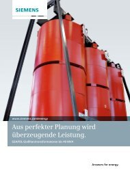
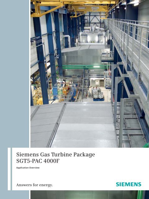
<strong>Siemens</strong> <strong>Gas</strong> <strong>Turbine</strong> <strong>Package</strong><br />
<strong>SGT5</strong>-<strong>PAC</strong> <strong>4000F</strong><br />
Application Overview<br />
Answers for energy.
2 |<br />
<strong>Siemens</strong> <strong>Gas</strong> <strong>Turbine</strong> <strong>Package</strong>s –<br />
Serving Your Project Needs<br />
<strong>Siemens</strong> supplies standardized and preengineered<br />
gas turbine packages customized<br />
to match specific project needs in<br />
the form of simple cycle gas turbine power<br />
plants and combined cycle power plants.<br />
The standard <strong>Siemens</strong> <strong>Gas</strong> <strong>Turbine</strong> <strong>Package</strong><br />
(SGT-<strong>PAC</strong>) combines the essential mechanical,<br />
electrical, and control equipment to<br />
serve a variety of project scopes effectively.<br />
The <strong>SGT5</strong>-<strong>PAC</strong> <strong>4000F</strong> is a key package<br />
for 50 Hz markets. The vital component<br />
is our advanced <strong>Siemens</strong> gas turbine<br />
<strong>SGT5</strong>-<strong>4000F</strong>.
A <strong>Siemens</strong> <strong>Gas</strong> <strong>Turbine</strong> <strong>Package</strong> is:<br />
A cost-effective power generating<br />
system with pre-engineered and standardized<br />
design and base scope of<br />
supply, with interconnecting piping<br />
and wiring pre-assembled to a large<br />
degree.<br />
Flexible in design and scope thanks<br />
to pre-engineered options to meet<br />
project- and site-specific conditions,<br />
capable of increasing the operating<br />
flexibility and performance of an<br />
existing power generating system.<br />
These options can replace or add<br />
systems to the base scope.<br />
Focused on the core equipment of a<br />
self-contained power generating system<br />
for power plants with gas turbines, it<br />
consists of gas turbine and electrical<br />
generator as well as all the systems<br />
required for the safe and reliable operation<br />
of these components: air intake<br />
system, exhaust gas system, electrical<br />
systems, instrumentation and control,<br />
generator excitation system, start-up<br />
system, and such major auxiliaries<br />
as the fuel system and lube oil system.<br />
The development of this package stems<br />
from the requirements of the utility<br />
industry for low initial cost and a rapid<br />
and reliable on-line generation system.<br />
It is equally well-suited to meet the<br />
requirements of industrial users. Heat<br />
recovery applications include combined<br />
cycle, repowering, and cogeneration<br />
in a wide range of environments and<br />
requirements.<br />
The <strong>SGT5</strong>-<strong>PAC</strong> <strong>4000F</strong> is used for<br />
Generation of electrical power<br />
Combined heat and power<br />
Simple cycle gas turbine power plants<br />
Multi-shaft combined cycle power<br />
plants<br />
operated in<br />
Base load service<br />
Intermediate load service<br />
Peak load service<br />
| 3
4 |<br />
Design Features and Arrangement<br />
The design of the <strong>Siemens</strong> <strong>Gas</strong> <strong>Turbine</strong><br />
<strong>Package</strong> represents over 50 years of<br />
experience in gas turbine technology<br />
and power plant design, resulting in a<br />
reliable self-contained electric power<br />
generating system.<br />
The <strong>SGT5</strong>-<strong>PAC</strong> <strong>4000F</strong> scope of supply<br />
represents the core equipment for a<br />
power plant equipped with gas turbines:<br />
<strong>Gas</strong> turbine<br />
Electrical generator<br />
Air intake system<br />
Exhaust gas system<br />
Start-up system<br />
Major auxiliary system<br />
Instrumentation and control<br />
Electrical systems<br />
Power control center<br />
Enclosures<br />
Fire protection<br />
Generator systems<br />
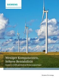
<strong>SGT5</strong>-<strong>PAC</strong> <strong>4000F</strong> design<br />
with the filter-house in<br />
top position<br />
To minimize field assembly and the need<br />
for piping fabrication during construction,<br />
<strong>Siemens</strong> utilizes a packaging and piping<br />
concept whenever possible. Moreover,<br />
subsystems have been grouped and installed<br />
in auxiliary packages.
Performance Data<br />
<strong>Siemens</strong> <strong>SGT5</strong>–<strong>PAC</strong> <strong>4000F</strong> <strong>Gas</strong> <strong>Turbine</strong><br />
<strong>Package</strong> and Combined Cycle Plant<br />
The performance data chart illustrates<br />
the application range of the <strong>Siemens</strong><br />
<strong>SGT5</strong>-<strong>PAC</strong> <strong>4000F</strong> <strong>Gas</strong> <strong>Turbine</strong> <strong>Package</strong><br />
and the multi-shaft combined cycle plant<br />
as a typical application of the package.<br />
<strong>SGT5</strong>-<strong>PAC</strong> <strong>4000F</strong> SCC5-<strong>4000F</strong> 2x1<br />
(multishaft)<br />
Net power output (MW) 288 848<br />
Net efficiency (%) 39.5 58.5<br />
Net heat rate (kJ/kWh) 9,114 6,158<br />
Net heat rate (Btu/kWh) 8,638 5,836<br />
Exhaust temperature (°C/°F) 580/1,075<br />
Exhaust mass flow (kg/s) 688<br />
Exhaust mass flow (lb/s) 1,516<br />
Generator type<br />
Data at ISO ambient conditions<br />
Air-cooled<br />
| 5
6 |<br />
Customer Benefits<br />
due to Extended Fleet Experience<br />
A <strong>Siemens</strong> <strong>Gas</strong> <strong>Turbine</strong> <strong>Package</strong> is designed<br />
to meet customer requirements<br />
economically and flexibly. It is a costeffective<br />
power generating system with<br />
standardized base design and base scope<br />
of supply with interconnecting piping<br />
largely pre-assembled.<br />
Reliable project implementation<br />
with high product quality<br />
through standardization of design with<br />
pre-defined interfaces to the overall power<br />
plant and use of proven components.<br />
High reliability<br />
through robust component and system<br />
designs and implementation of large fleet<br />
operating experience (total gas turbine<br />
fleet experience: > 1,240 units, > 220 GW,<br />
> 28 Million operating hours.<br />
High availability<br />
through service-friendly components<br />
and optional diagnostic service.<br />
Fuel cost savings<br />
through high component efficiencies<br />
and short start-up times.<br />
Environmental friendliness<br />
through low emissions and<br />
high efficiencies.<br />
High operating flexibility<br />
through use of online-change to different<br />
fuels and through excellent start-up and<br />
part load operating capabilities.<br />
Flexibility to match customer-<br />
and site-specific needs<br />
through pre-defined options that can<br />
be changed or added to the base scope.<br />
Fast construction times<br />
through shipment of pre-assembled<br />
system to site.<br />
Compact plant size<br />
through small-footprint arrangement<br />
of systems.<br />
World-wide experience<br />
The <strong>SGT5</strong>-<strong>4000F</strong> has been in service since<br />
1997. Over 190 engines of this advanced<br />
gas turbine family are in operation,<br />
and over 65 are on order. More than<br />
4,727,000 (as of Aug 2009) cumulative<br />
operating hours and a fleet reliability<br />
exceeding 99 % have been achieved.<br />
<strong>Siemens</strong> Simple Cycle Applications<br />
The <strong>SGT5</strong>-<strong>PAC</strong> <strong>4000F</strong> is a self-contained<br />
electric power generating system suitable<br />
for simple cycle base load, intermediate<br />
load and peaking applications. Features<br />
proven in previous designs have been<br />
incorporated into the SSC5-<strong>4000F</strong> power<br />
plant. These include<br />
Factory assembled fuel, auxiliary,<br />
mechanical, and electrical packages<br />
Enclosures for turbine and auxiliary<br />
packages<br />
A microprocessor-based control system<br />
A starting frequency converter system<br />
<strong>Siemens</strong> Combined Cycle Applications<br />
<strong>Siemens</strong> has more than three decades<br />
of experience in combined cycle plant<br />
design. That is why <strong>Siemens</strong> Combined<br />
Cycle Plants (SCC) affiliates the economical<br />
benefits of a pre-engineered power<br />
plant design with outstanding flexibility<br />
through a wide range of options. Single<br />
as well as multi-shaft configurations<br />
are available.<br />
The current SCC5-<strong>4000F</strong> <strong>Siemens</strong><br />
Combined Cycle Plants incorporate the<br />
vast expertise and experience gained<br />
from many previous design accomplishments.<br />
The SCC5-<strong>4000F</strong> family is dimensioned<br />
to meet the various base and cycle<br />
load requirements of utilities, independent<br />
power producers, industrial users, and<br />
merchant plant operators. The development<br />
of these designs allows for costeffective<br />
plants with minimum projectspecific<br />
engineering.
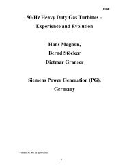
Typical plant layout for single-unit gas turbine package<br />
30 m<br />
6a<br />
6b<br />
= options<br />
5<br />
5<br />
3a<br />
7<br />
60 m<br />
43 m<br />
3b<br />
87 m<br />
2c 8<br />
2d<br />
2a 2b<br />
(<strong>Gas</strong> turbine package layout for a typical 2x1 multi-shaft arrangement)<br />
1<br />
4a 4b<br />
Plant Arrangement Diagram<br />
Plant arrangements and s ystems configuration<br />
are illustrated in the chart above.<br />
9a 9b 9b<br />
1 <strong>Gas</strong> <strong>Turbine</strong><br />
2a Auxiliary Systems Module for Fuel <strong>Gas</strong>,<br />
Hydraulic Oil, Instrument Air, Lube Oil<br />
2b Auxiliary Systems Module for Fuel Oil,<br />
Purge Water, NO X Water<br />
2c Compressor Cleaning Skid<br />
2d Compressor Dehumidifier Skid<br />
3a Air Intake Filter House<br />
(envelope is shown schematically)<br />
3b Air Intake Duct<br />
4a Exhaust <strong>Gas</strong> Diffuser<br />
4b Stack or Bypass Stack with Diverter Damper<br />
5 Power Control Center with Electrical<br />
and I&C Equipment<br />
6a Low Voltage Transformer for<br />
Static Excitation Equipment<br />
6b Low Voltage Transformer for<br />
Starting Frequency Converter<br />
7 Electrical Generator<br />
8 CO 2 Fire Protection<br />
9a Lube Oil Fin-Fan Cooler<br />
9b Generator Fin-Fan Cooler<br />
<strong>Siemens</strong> <strong>Gas</strong> <strong>Turbine</strong><br />
<strong>Package</strong> <strong>SGT5</strong>-<strong>PAC</strong> <strong>4000F</strong><br />
in a multi-shaft combined<br />
cycle power plant<br />
| 7
8 |<br />
<strong>SGT5</strong>-<strong>4000F</strong> <strong>Gas</strong> <strong>Turbine</strong><br />
Compressor<br />
Type Disk-type hollow shaft<br />
Number of Stages 15<br />
Rotor Speed 3,000 rpm<br />
Pressure Ratio 18:1<br />
Inlet Guide Vanes One row variable<br />
Combustion System<br />
Combustors<br />
Type 1 ring combustor system<br />
Configuration Annular<br />
Fuel <strong>Gas</strong>eous and liquid<br />
Number 24<br />
Fuel Pressure Range<br />
Natural <strong>Gas</strong> 27 bar–33 bar; Nominal @ gas turbine;<br />
Filter inlet flange<br />
<strong>Turbine</strong><br />
Number of Stages 4<br />
Number of Cooled Stages 3<br />
Bearings<br />
Journal Bearing<br />
Type Tilting pad<br />
Quantity 1<br />
Thrust Bearing Drive end<br />
Number 1<br />
Drive<br />
Generator coupled to cold end of<br />
turbine via intermediate shaft<br />
Technical Data<br />
In the following table data are provided<br />
for planning purposes.<br />
Weights and Dimensions<br />
SGen5-1000A Generator<br />
Generator rating @ 40°C air inlet temperature, TEWAC<br />
kVA 334,000<br />
kW 283,900<br />
P.F. 0.85<br />
Voltage (Volts)<br />
20,000<br />
line-to-line<br />
Calculated short circuit 0.49<br />
ratio<br />
Speed (rpm) 3,000<br />
Frequency (Hz) 50<br />
Line current (Amps) 9,641<br />
Altitude (meters) Sea level<br />
Insulation<br />
Class of insulation Stator-class –<br />
F with class B temperature rise<br />
Field-class –<br />
F with class B temperature rise<br />
Shown below is a typical list of the major pieces of equipment along<br />
with their approximate nominal shipping weights and nominal dimensions<br />
Item<br />
<strong>Gas</strong> <strong>Turbine</strong><br />
Length Width Height Weight Remarks<br />
<strong>SGT5</strong>-<strong>PAC</strong> <strong>4000F</strong> <strong>Gas</strong> <strong>Turbine</strong><br />
Auxiliary Systems<br />
10.8 m 5.2 m 4.8 m 312,000 kg<br />
Module for Fuel <strong>Gas</strong> Operation 11.5 m 3.3 m 3.8 m 20,000 kg<br />
Module for Fuel Oil Operation<br />
Compressor Cleaning System<br />
9.5 m 3.3 m 3.2 m 24,000 kg<br />
Base Version 1.9 m 1.1 m 1.6 m 850 kg<br />
Advanced Cleaning System<br />
Air Intake System<br />
2.7 m 2.0 m 2.2 m 1,500 kg<br />
Filterhouse 14 m 18 m 11 m 120,000 kg<br />
Silencer * 9.5 m 7 m *<br />
Duct<br />
Generator<br />
SGen5-1000A Generator<br />
9.5 m 2.2 m 18 m 50,000 kg<br />
Assembled (with enclosure) 14.11 m 8.63 m 5.94 m 359,000 kg<br />
Shipping 13 m 4.6 m 4.4 m 318,000 kg<br />
Power Control Center<br />
(*= project-specific)<br />
12.28 m 3.64 m 3.33 m 22,000 kg
8<br />
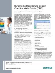
<strong>SGT5</strong>-<strong>4000F</strong><br />
1 Casing<br />
Horizontally split<br />
2 Supports<br />
Fixed at compressor end<br />
Flexible at turbine end<br />
3 Rotor<br />
Disk-type hollow shaft<br />
Combined thrust and journal<br />
bearing at compressor end<br />
Journal bearing at turbine end<br />
Compressor and turbine disks<br />
interlocked via Hirth serrations<br />
Compressor and turbine disks<br />
axially fixed via one central tie bolt<br />
4 Compressor<br />
15-Stage axial<br />
Variable-pitch inlet guide vanes<br />
4<br />
5<br />
3<br />
6<br />
5 Combustion<br />
Annular chamber with ceramic<br />
and metallic heat shields<br />
24 hybrid burners<br />
Dry low-NO X technology<br />
Operation with gaseous<br />
and liquid fuels<br />
6 <strong>Turbine</strong><br />
4-Stage<br />
Thermal barrier blade coatings<br />
Convection and impingement<br />
cooling of blade interior<br />
Film cooling of blade airfoil surface<br />
7 Exhaust<br />
Axial flow<br />
8 Generator coupling<br />
At cold end drive<br />
2<br />
1<br />
7<br />
| 9
10 |<br />
Auxiliary Systems<br />
Fuel<br />
<strong>Gas</strong> fuel system supplies gaseous fuel<br />
with adequate mass flow to the gas<br />
turbine.<br />
Fuel oil system as an option supplies<br />
liquid fuel with adequate mass flow<br />
to the gas turbine.<br />
Optionally, a dual-fuel system provides<br />
highest fuel flexibility.<br />
Rotor turning<br />
Turning device – the gas turbine rotor<br />
is rotated at low speed, for start-up,<br />
shutdown, and extended standstills.<br />
Hydraulic Clearance Optimization<br />
The HCO (Hydraulic Clearance<br />
Optimization) power unit, supplies<br />
hydraulic oil for shifting the gas<br />
turbine rotor into the best-performance<br />
position with minimized<br />
clearances on the turbine side.<br />
Cleaning<br />
A mobile compressor cleaning system<br />
supplies water for the compressor<br />
wash procedure to maintain high<br />
compressor efficiency.<br />
Start-up<br />
Starting frequency converter (SFC)<br />
for static start-up.<br />
Valve actuation<br />
A hydraulic oil system provides highpressure<br />
hydraulic oil to operate the<br />
control and emergency stop valves<br />
of the fuel systems and NO X water<br />
system.<br />
Instrument air system for the supply<br />
of compressed air to operate the<br />
pneumatic actuators (e.g., blow-off<br />
valves).<br />
Lubrication<br />
Lube oil system – supplies lubrication<br />
oil to the gas turbine, the generator,<br />
and the HCO power unit and supplies<br />
lifting oil to the gas turbine, the<br />
generator, and the hydraulic-type<br />
rotor turning device.
Air filter Exhaust<br />
Air<br />
intake<br />
Filter system<br />
Compressor<br />
Cleaning spray<br />
Nozzle system<br />
<strong>Gas</strong> turbine<br />
– Two-stage static filter<br />
– Self-cleaning pulse filter (optional)<br />
Air Intake System<br />
Functions<br />
Guiding and filtering of ambient air<br />
to the gas turbine for reliable operation<br />
Reducing noise from the gas turbine<br />
compressor to permissible levels<br />
System scope<br />
Filter house with filter system<br />
Air intake duct with silencer<br />
Air filter Exhaust<br />
Air stack<br />
intake<br />
Evaporative<br />
cooling*<br />
Inlet air cooling<br />
<strong>Gas</strong> turbine<br />
* option<br />
Inlet air cooling provides more power<br />
when needed:<br />
– under hot and dry ambient conditions<br />
– at times of high power demand<br />
Design<br />
Top inlet air intake: the filter house<br />
is located above the generator and<br />
inlet duct and extends vertically to<br />
the gas turbine<br />
House configuration: the support<br />
structure is supplied with existing<br />
building structure (civil scope)<br />
Compressor cleaning spray nozzle<br />
system<br />
Filter Systems: static filter as<br />
standard, pulse filter as an option<br />
Anti-icing system can be provided<br />
Inlet air cooling systems on request<br />
Air<br />
Filter house<br />
M<br />
Compressor<br />
<strong>Gas</strong> turbine<br />
Air anti-icing<br />
The anti-icing system avoids<br />
ice effects under very cold<br />
ambient conditions and thus<br />
avoids pressure losses<br />
| 11
12 |<br />
Exhaust <strong>Gas</strong> System Enclosures<br />
Functions – Exhaust system<br />
The system guides exhaust gas<br />
from the gas turbine via the diffuser<br />
to the stack of a gas turbine plant,<br />
or to the heat recovery steam generator<br />
of a combined cycle plant. <strong>Gas</strong> turbine<br />
availability can be increased with a<br />
diverter and bypass stack for combined-cycle<br />
power plants.<br />
At the same time, the system<br />
reduces noise from the gas turbine<br />
to permissible levels.<br />
System scope<br />
Exhaust diffuser<br />
Exhaust stack for simple cycle<br />
plants as an option for simple cycle<br />
applications<br />
Diverter damper with bypass stack<br />
for combined cycle plants as an option<br />
for combined cycle applications<br />
Functions<br />
Indoor enclosures:<br />
Optimum noise protection<br />
at indoor installation<br />
in the turbine building<br />
Delineation of<br />
hazardous areas<br />
Containment of fire<br />
suppression agent<br />
Weather enclosures<br />
are available on request:<br />
Noise and weather<br />
protection for<br />
outdoor installation<br />
System scope<br />
Enclosures when applicable with:<br />
Ventilation system<br />
Fire detection system<br />
Fire fighting system<br />
<strong>Gas</strong> detection system
Electrical and Control System<br />
Functions – Electrical system<br />
<strong>Energy</strong> supply for package equipment<br />
Generator protection, excitation,<br />
and static start-up equipment<br />
System scope<br />
AC/DC low-voltage switchgear and<br />
motor control centers for gas turbine<br />
consumers<br />
Uninteruptable power supplies<br />
(batteries, chargers, DC/DC-converters)<br />
for gasturbine consumers<br />
Generator protection, synchronization<br />
equipment, measurement of electrical<br />
values<br />
Power control center (standard)<br />
to accommodate the electrical and<br />
instrumentation and control equipment<br />
Static excitation system for the<br />
electrical generator<br />
Starting frequency converter for<br />
gas turbine start-up<br />
Low voltage transformers for the<br />
static excitation equipment and<br />
starting the frequency converter<br />
Functions – SPPA-T3000 Control system<br />
Open loop control: step sequences<br />
for start-up and shutdown, drive<br />
control<br />
Closed loop control: fuel valves,<br />
compressor<br />
Inlet guide vane variation<br />
Protection: engine protection,<br />
failsafe protection circuits<br />
Operation and monitoring:<br />
human-machine-interface<br />
SPPA-T3000 Control System<br />
System scope and functions<br />
Operating and monitoring of the plant<br />
Automation (basic automation, turbine<br />
control, failsafe protection)<br />
Engineering of the instrumentation<br />
and control system<br />
Diagnostics on the instrumentation<br />
and control system<br />
Diagnostics on the package<br />
Bus systems<br />
Benefits<br />
Single user interface for all functions,<br />
from anywhere<br />
Intuitive links throughout the entire<br />
system<br />
Speeds up the work-flow<br />
| 13
14 |<br />
Power Control Center<br />
Features of the Power Control Center<br />
The features of the Power Control Center<br />
(PCC) modules make them equivalent<br />
to a conventional housing/building:<br />
The degree of protection of the<br />
switchgear rooms is IP 54.<br />
The switchgear room temperature in<br />
the PCC modules is controlled between<br />
10 °C and 35 °C by air-conditioning<br />
units. At least one redundant airconditioning<br />
aggregate is provided.<br />
The air is cleaned by a filter. The<br />
sealed construction prevents any<br />
ingress of moisture or dust by leakage.<br />
In addition, the heat exchangers<br />
dehydrate the replacement air so<br />
that condensation inside the modules<br />
cannot occur.
SGen5-1000A<br />
One generator assembly consisting of<br />
the following components is delivered<br />
to the site:<br />
Bedplate<br />
Spring mounted stator<br />
Bearing pedestals<br />
Rotor with shrunk-on collector<br />
Stator inner enclosure<br />
At the site, an outer enclosure is erected<br />
around the generator that includes<br />
coolers, current transformers, and<br />
neutral grounding equipment.<br />
The SGen5-1000A air-cooled generator<br />
features:<br />
165 – 350 MVA range<br />
(at 40 °C cold gas condition)<br />
World class efficiency with low<br />
maintenance design<br />
Multi-zone, indirectly cooled<br />
stator windings<br />
Roebelled stator windings with<br />
brazed solid end connections<br />
Radially ventilated stator core<br />
attached to bedplate<br />
Global Vacuum Pressure Impregnated<br />
(GVPI) stator core and stator winding<br />
Core suspended on two axial springs<br />
Radially ventilated and cooled rotor<br />
winding<br />
Two low pressure “push” fans<br />
mounted at each end of the rotor<br />
Weather and sound proof outer<br />
generator enclosure<br />
Coolers mounted on foundation<br />
beside bedplate and inside outer<br />
enclosure for a TEWAC (Totally<br />
Enclosed Water to Air-cooled)<br />
generator<br />
Overhung collector and brush<br />
holders bedplate<br />
The stator bedplate is a heavy steel<br />
fabrication, which supports the stator<br />
core and windings, bearing pedestals,<br />
rotor assembly excitation casing, and<br />
the inner enclosure. The bedplate rests<br />
on leveling devices (fixators) affixed<br />
to the foundation and is secured with<br />
foundation bolts and axial and transverse<br />
anchors. Features for lifting and suitable<br />
jacking points for alignment to the turbine<br />
are also provided.<br />
| 15
16 |<br />
Power Diagnostics<br />
Power Diagnostics® Services<br />
Remote online monitoring of entire power<br />
plants or vital power plant components<br />
via <strong>Siemens</strong> Power Diagnostics Services<br />
is a key to mitigate risk for long-term<br />
service contracts. Based on several Power<br />
Diagnostics Centers worldwide <strong>Siemens</strong><br />
provides the Service of daily Online Remote<br />
Diagnostics exclusively for Customers<br />
with long-term service agreements.<br />
Currently more than 300 advanced frame<br />
gas turbines, as well as heat recovery<br />
boilers, steam turbines and generators<br />
are monitored via those centers by<br />
<strong>Siemens</strong> experts to ensure the most<br />
trouble-free operation.<br />
The WIN_TS diagnostic system including<br />
a broadband connection for unlimited<br />
remote access has to be installed for<br />
online remote diagnostic services. The<br />
connection of a phone line exclusively<br />
assigned for the use of WIN_TS or an<br />
internet link is required as a contractual<br />
obligation of the customer already before<br />
commissioning starts.<br />
Benefits<br />
During plant operation, online remote<br />
diagnostics provide the following<br />
advantages:<br />
Plants can be monitored effectively<br />
by Power Diagnostics Centers and<br />
OEM experts, e.g., of forced outages<br />
or emerging damages by detection<br />
of possible engine failures before they<br />
occur can be avoided<br />
Risk mitigation through service support<br />
for O&M and LTP during gas turbine<br />
life cycle, e.g., condition based outage<br />
planning by <strong>Siemens</strong> with the strong<br />
support of <strong>Siemens</strong> experts from all<br />
disciplines<br />
Detailed information on plant’s history,<br />
long term trends, and optimization of<br />
operational reliability and availability<br />
It also supports<br />
OEM’s engineering staff in developing<br />
their modernization and upgrade<br />
programs as well as Performance<br />
Enhancement Programs and optimization<br />
of Operational Reliability and<br />
Availability Programs<br />
Your benefits include:<br />
Improved performance in terms of<br />
availability, reliability, efficiency and<br />
flexibility<br />
Reduced maintenance costs by extended<br />
maintenance intervals, condition based<br />
maintenance and shorter outages
Service and Support<br />
Corrective & preventive maintenance<br />
Expecting a reliable high output from<br />
your plant, we set the goal to help you<br />
cut downtimes to a minimum. With our<br />
diagnostic services we can even identify<br />
faults before they become failures. From<br />
installation and commissioning, scheduled<br />
overhauls, on-site/factory repairs<br />
to spare parts, we are ready to serve you.<br />
With our remote monitoring & diagnostics<br />
capabilities we can help you instantly.<br />
Our global team of more than 3,000 highly<br />
qualified <strong>Siemens</strong> service specialists is<br />
dedicated to providing sound, reliable<br />
and continuing support. Anywhere, any<br />
time.<br />
Service agreements<br />
To plan well ahead a service agreement<br />
for your plant can best support your long-<br />
term goals. We can help proactively boost<br />
your plant’s performance through various<br />
service options. From operating plant<br />
service agreements to full-scope operation,<br />
maintenance contracts and remote monitoring<br />
– <strong>Siemens</strong> <strong>Energy</strong>’s service solutions<br />
can be adapted to your exact needs:<br />
scheduled inspections, preventive maintenance,<br />
remote monitoring, replacement<br />
parts programs and incentives.<br />
In addition, we offer on-site operation &<br />
maintenance contracts for power plants.<br />
Benefits include:<br />
Optimized return on investment<br />
Optimized performance<br />
Optimized strategic planning<br />
for operating assets<br />
Reduced maintenance costs<br />
Training & Consulting <strong>Siemens</strong> Power<br />
Academy (SPA)<br />
Training courses and programs designed<br />
to provide you essential knowledge of<br />
equipment and systems ensure your safe,<br />
reliable operation and routine maintenance<br />
for your assets.<br />
| 17
18 |<br />
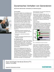
<strong>SGT5</strong>-<strong>4000F</strong> Steam Production<br />
Steam production [kg/s]<br />
150<br />
145<br />
140<br />
135<br />
130<br />
125<br />
120<br />
115<br />
110<br />
105<br />
100<br />
95<br />
90<br />
204 °C<br />
260 °C<br />
Cogeneration or<br />
Combined Heat and Power<br />
General description<br />
Owners and operators of industrial and<br />
commercial facilities are actively looking<br />
for ways to use energy more efficiently.<br />
One option is cogeneration, also known<br />
as combined heat and power (CHP).<br />
Cogeneration/CHP consists of simultaneous<br />
production of electricity and useful<br />
heat from the same fuel or energy.<br />
The owner of a <strong>SGT5</strong>-<strong>PAC</strong> <strong>4000F</strong> cogen<br />
system can use it to produce their own<br />
electricity, produce electricity for sale<br />
to others, or use the excess (waste) heat<br />
for process steam, hot water heating,<br />
space heating and other thermal needs.<br />
The excess heat also can be used to<br />
produce steam that can drive a steam<br />
turbine-generator to produce additional<br />
electricity. A <strong>SGT5</strong>-<strong>PAC</strong> <strong>4000F</strong>-based cogen<br />
system can be designed, with the addition<br />
of the appropriate heat recovery boiler<br />
Saturated<br />
316 °C<br />
371 °C<br />
427 °C<br />
482 °C<br />
538 °C<br />
5 15 25 35 45 55 65 75<br />
and steam turbine-generator, to use the<br />
maximum amount of available energy.<br />
The steam turbine can be selected from<br />
extraction, condensing or backpressure<br />
styles to best match the customer’s process<br />
steam and electricity requirements.<br />
Steam production calculation<br />
The figure above shows the typical<br />
steam production capability of the<br />
<strong>SGT5</strong>-<strong>PAC</strong> <strong>4000F</strong> for a range of steam<br />
pressures and temperatures.<br />
The referenced results are for<br />
Base load operation at sea level,<br />
15 °C compressor inlet temperature,<br />
60 % relative humidity of the air and<br />
Natural gas fuel.<br />
Steam pressure [bar]<br />
The heat recovery system chosen has<br />
one pressure level, a 8.3 K pinch point,<br />
5.5 K approach temperature and no<br />
supplementary firing. Although steam<br />
production varies depending on site<br />
conditions and gas turbine loading,<br />
the figure provides an estimate of what<br />
can be achieved with a <strong>SGT5</strong>-<strong>PAC</strong> <strong>4000F</strong>.
References<br />
Hamm-Uentrop, Germany<br />
Trianel Power Kraftwerk Hamm-Uentrop<br />
GmbH & Co. KG operates the combined cycle<br />
power plant with a total capacity of 850 MW.<br />
Included in the scope are two gas turbine<br />
packages <strong>SGT5</strong>-<strong>PAC</strong> <strong>4000F</strong>.<br />
Al Taweelah,<br />
United Arab Emirates<br />
Al Taweelah A2 is the first IPP project in the<br />
Middle East. The project with an output of 780 MW<br />
represents the first combination of a combined<br />
cycle power plant with a desalination plant.<br />
The scope included three gas turbine packages<br />
<strong>SGT5</strong>-<strong>PAC</strong> <strong>4000F</strong> and two steam turbines.<br />
Panglima, Malaysia<br />
Panglima Power Sdn Bhd operates the combined<br />
cycle power plant with a multi-shaft 2 x 1 unit that<br />
has a total capacity of 780 MW, including two gas<br />
turbine packages <strong>SGT5</strong>-<strong>PAC</strong> <strong>4000F</strong>.<br />
Antalya, Turkey<br />
The Ali Metin Kazanci Power Plant in Antalya,<br />
Turkey consists of two gas turbine packages<br />
<strong>SGT5</strong>-<strong>PAC</strong> <strong>4000F</strong>. The power plant is built and<br />
operated by the Turkish company AKSA and<br />
covers a major part of the high energy demand<br />
in Antalya – one of the major tourist areas in<br />
Turkey. The 520 MW Open Cycle plant was built<br />
by AKSA in world record time. In a second phase<br />
this plant will be completed by AKSA to an<br />
780 MW Combined Cycle Power Plant with<br />
one <strong>Siemens</strong> Steam <strong>Turbine</strong> <strong>Package</strong> SST-5000.<br />
| 19
Published by and copyright © 2009:<br />
<strong>Siemens</strong> AG<br />
<strong>Energy</strong> Sector<br />
Freyeslebenstrasse 1<br />
91058 Erlangen, Germany<br />
<strong>Siemens</strong> <strong>Energy</strong>, Inc.<br />
4400 Alafaya Trail<br />
Orlando, FL 32826-2399, USA<br />
For more information, please contact<br />
our Customer Support Center.<br />
Phone: +49 180/524 70 00<br />
Fax: +49 180/524 24 71<br />
(Charges depending on provider)<br />
E-mail: support.energy@siemens.com<br />
Fossil Power Generation Division<br />
Order No. E50001-G210-A130-X-4A00<br />
Printed in Germany<br />
Dispo 34802, c4bs No. 7813, 7448, 7449<br />
TH 214-090649 430173 WS 09092.0<br />
Printed on elementary chlorine-free bleached paper.<br />
All rights reserved.<br />
Trademarks mentioned in this document<br />
are the property of <strong>Siemens</strong> AG, its affiliates,<br />
or their respective owners.<br />
Subject to change without prior notice.<br />
The information in this document contains general<br />
descriptions of the technical options available, which<br />
may not apply in all cases. The required technical<br />
options should therefore be specified in the contract.<br />
www.siemens.com/energy