Safety Check Valve Series 580/581 Waferchek Serving the gas ...
Safety Check Valve Series 580/581 Waferchek Serving the gas ...
Safety Check Valve Series 580/581 Waferchek Serving the gas ...

Create successful ePaper yourself
Turn your PDF publications into a flip-book with our unique Google optimized e-Paper software.
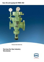
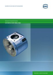
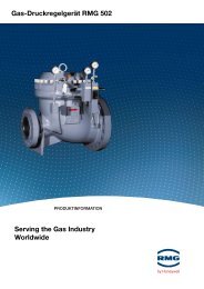
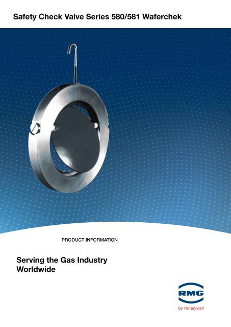
<strong>Safety</strong> <strong>Check</strong> <strong>Valve</strong> <strong>Series</strong> <strong>580</strong>/<strong>581</strong> <strong>Waferchek</strong><br />
Product information<br />
<strong>Serving</strong> <strong>the</strong> <strong>gas</strong> industry<br />
Worldwide
2<br />
SAFETY CHECK VALVE SERiES <strong>580</strong>/<strong>581</strong> WAFERCHEK<br />
introduction<br />
• The <strong>Series</strong> <strong>580</strong> and <strong>581</strong> is a wafer type, self acting offset disc check valve, designed for fitting between flanges.<br />
• The <strong>Series</strong> <strong>581</strong> is specifically designed for use with below ground Gas Control Module installations.<br />
Application<br />
• The valve is primarily intended for use in conjunction with safety cut-off valves (slamshut) in <strong>gas</strong> pressure<br />
regulator installations feeding a common district network or industrial premises. Its purpose is to automatically<br />
identify and initiate <strong>the</strong> isolation of a faulty (excess throughput) regulator, whilst protecting a healthy regulator<br />
against inadvertent shut-off.<br />
• The regulator locations may be adjacent, as a twin or multiple streams, or in widely separated single<br />
installations, since <strong>the</strong> incorporation of a <strong>Waferchek</strong> valve at each individual regulator outlet renders each<br />
installation self-contained. This enables a common pressure setting to be adopted on all <strong>the</strong> slamshut valves<br />
incorporated in <strong>the</strong> same <strong>gas</strong> supply network.<br />
• The valve may also be used as a conventional check valve in applications requiring <strong>the</strong> prevention of reverse<br />
mass flow, but where a small amount of reverse leakage can be tolerated. Not suitable for use on fan blower,<br />
<strong>gas</strong> booster etc.<br />
SERViCE CONDiTiONS<br />
Maximum Working Pressure:<br />
Constructional Strength:<br />
Reverse Pressure<br />
Differential:<br />
<strong>Series</strong> <strong>580</strong><br />
<strong>Series</strong> <strong>581</strong><br />
Temperature Range:<br />
Medium:<br />
SiZE RANgE<br />
<strong>Series</strong> <strong>580</strong> <strong>Series</strong> <strong>581</strong><br />
50mm, 80mm, 100mm<br />
200mm<br />
150mm, 200mm<br />
250mm, 300mm<br />
installation<br />
7 barg (100 psig)<br />
19 barg (275 psig)<br />
1 barg (14.5 psig)<br />
0.34 barg (5 psig)<br />
-20ºC to +60ºC<br />
Natural and manufactured <strong>gas</strong>es<br />
of non-aggressive nature.<br />
• Suitable for mounting in horizontal mains only. To be<br />
installed with body tapping (hook bolt) to <strong>the</strong> top<br />
centre and nameplate arrow pointing in <strong>the</strong> direction<br />
of <strong>gas</strong> flow.<br />
• The standard unit locates centrally within <strong>the</strong> bolt<br />
circle of flanges to PN16:BS EN 1092-2:1997, care<br />
to be taken to ensure clearance in <strong>the</strong> downstream<br />
main and that <strong>the</strong> flange joint does not interfere with<br />
<strong>the</strong> valve door movement.<br />
Pressure Loss<br />
Due to <strong>the</strong> light door construction, <strong>the</strong> pressure<br />
drop is very low, e.g., 1.25mbarg (0.5" wg), when<br />
<strong>the</strong> door is in <strong>the</strong> fully open position after which<br />
Square Law Flow (approx.) applies. Ht STP<br />
conditions <strong>the</strong> pressure drop may be obtained<br />
directly from <strong>the</strong> graph.<br />
At o<strong>the</strong>r conditions of pressure <strong>the</strong> following<br />
formula applies:<br />
Pressure drop in mbarg or Pressure drop in ins. w.g.<br />
Hm x 1.013 m bar Hi x 14.7 in. w.g.<br />
Pu Pu<br />
Where Hm and Hi = pressure drop from graph<br />
Pu = Upstream pressure, bar abs, or p.s.i.a<br />
(dependent upon formula used)<br />
Flow x 1000 Scfh 0.6 Gas<br />
Flow x 1000 M³/Hour 0.6 Gas
Leakage<br />
The <strong>Waferchek</strong> valve does not have a tight seal and a<br />
small amount of reverse leakage will take place, this<br />
will not exceed <strong>the</strong> flows given in <strong>the</strong> table below for<br />
reverse pressure differential of up to 1 barg (14.5 psig)<br />
for <strong>the</strong> <strong>Series</strong> <strong>580</strong> and 0.34 barg (5 psig) for <strong>the</strong><br />
<strong>Series</strong> <strong>581</strong>.<br />
<strong>Valve</strong> Size<br />
mm<br />
ins<br />
50<br />
2<br />
80<br />
Leakage <strong>gas</strong> (Sg 0.6)<br />
Sm³/hr<br />
scfh<br />
10.6<br />
375<br />
DiMENSiONS AND WEigHTS<br />
3<br />
100<br />
4<br />
150<br />
Size A B C D E Wt.kg<br />
50 43.4 50 106 19 21 0.9<br />
80 66.4 80 140 19 37 1.35<br />
100 86.7 100 161 22 50 2.35<br />
150 136.4 150 216 22 83 3.62<br />
200 181.4 200 273 22 113 5.45<br />
250 226.4 250 330 35 140 26.5<br />
300 271.4 300 384 35 172 33.5<br />
All dimensions in mm<br />
CB<br />
14.2<br />
500<br />
19.8<br />
700<br />
6<br />
22.7<br />
800<br />
200<br />
8<br />
28.3<br />
1000<br />
250<br />
10<br />
31.2<br />
1100<br />
SAFETY CHECK VALVE SERiES <strong>580</strong>/<strong>581</strong> WAFERCHEK<br />
300<br />
12<br />
31.2<br />
1100<br />
Note: A hook bolt is provided to facilitate installation<br />
A<br />
B<br />
Normal Flow<br />
E D<br />
Minimum length of straight pipe downstream<br />
Inlet Isolating<br />
<strong>Valve</strong><br />
Slamshut Pressure<br />
Regulator<br />
MATERiALS OF CONSTRUCTiON<br />
Component<br />
Body<br />
Door<br />
Spindle<br />
Spindle Bearings<br />
Door Seal<br />
Position of <strong>Waferchek</strong> <strong>Valve</strong> in Typical District governor installation<br />
All contents are subject to copyright, with <strong>the</strong> possible exception of information that is universal and/or public domain.<br />
Bryan Donkin RMG Gas Controls Limited policy is one of continuous improvement and development.<br />
The company reserves <strong>the</strong> right to change, withdraw and introduce improved designs without notice.<br />
Dimensions and Performance Data<br />
Material<br />
Carbon Steel<br />
<strong>580</strong> - Aluminium<br />
<strong>581</strong> - Nylon<br />
Stainless Steel<br />
Ceramic PTFE or<br />
Phosphor Bronze<br />
Nitrile Rubber<br />
Testing (for freedom of operation)<br />
Facilities are provided for testing <strong>the</strong> free movement of<br />
<strong>the</strong> valve in situ. With <strong>the</strong> pipe unpressurised, remove<br />
one end plug, insert screwdriver to engage slot in <strong>the</strong><br />
end of <strong>the</strong> door spindle. The door should rotate<br />
through an angle of 60° minimum and return freely to<br />
<strong>the</strong> vertical seating position.<br />
Discrimination<br />
System<br />
Relief<br />
<strong>Waferchek</strong> Outlet Isolating<br />
<strong>Valve</strong><br />
Final Outlet<br />
<strong>Safety</strong> Relief<br />
3
For More information<br />
To learn more about RMG's advanced <strong>gas</strong><br />
solutions, contact your RMG<br />
account manager or visit<br />
www.rmg.com<br />
gERMANY<br />
Honeywell Process Solutions<br />
RMG Regel + Messtechnik GmbH<br />
Osterholzstrasse 45<br />
34123 Kassel, Germany<br />
Tel: +49 (0)561 5007-0<br />
Fax: +49 (0)561 5007-107<br />
Honeywell Process Solutions<br />
RMG Messtechnik GmbH<br />
Otto-Hahn-Strasse 5<br />
35510 Butzbach, Germany<br />
Tel: +49 (0)6033 897-0<br />
Fax: +49 (0)6033 897-130<br />
Honeywell Process Solutions<br />
RMG Gaselan Regel + Messtechnik GmbH<br />
Julius-Pintsch-Ring 3<br />
15517 Fürstenwalde, Germany<br />
Tel: +49 (0)3361 356-60<br />
Fax: +49 (0)3361 356-836<br />
Honeywell Process Solutions<br />
WÄGA Wärme-Gastechnik GmbH<br />
Osterholzstrasse 45<br />
34123 Kassel, Germany<br />
Tel: +49 (0)561 5007-0<br />
Fax: +49 (0)561 5007-207<br />
POLAND<br />
Honeywell Process Solutions<br />
Gazomet Sp. z o.o.<br />
ul. Sarnowska 2<br />
63-900 Rawicz, Poland<br />
Tel: +48 (0)65 5462401<br />
Fax: +48 (0)65 5462408<br />
ENgLAND<br />
Honeywell Process Solutions<br />
Bryan Donkin RMG Gas Controls Ltd.<br />
Enterprise Drive, Holmewood<br />
Chesterfield S42 5UZ, England<br />
Tel: +44 (0)1246 501-501<br />
Fax: +44 (0)1246 501-500<br />
CANADA<br />
Honeywell Process Solutions<br />
Bryan Donkin RMG Canada Ltd.<br />
50 Clarke Street South, Woodstock<br />
Ontario N4S 0A8, Canada<br />
Tel: +1 (0)519 5398531<br />
Fax: +1 (0)519 5373339<br />
USA<br />
Honeywell Process Solutions<br />
Mercury Instruments LLC<br />
3940 Virginia Avenue<br />
Cincinnati, Ohio 45227, USA<br />
Tel: +1 (0)513 272-1111<br />
Fax: +1 (0)513 272-0211<br />
TURKEY<br />
Honeywell Process Solutions<br />
RMG GAZ KONT. SIS. ITH. IHR. LTD. STI.<br />
Birlik Sanayi Sitesi, 6.<br />
Cd. 62. Sokak No: 7-8-9-10<br />
TR - Sasmaz / Ankara, Turkey<br />
Tel: +90 (0)312 27810-80<br />
Fax: +90 (0)312 27828-23<br />
NRV <strong>580</strong>/<strong>581</strong><br />
2010-10<br />
© 2010 Honeywell International Inc.