implementation of schroeder reverberator on an fpga
implementation of schroeder reverberator on an fpga
implementation of schroeder reverberator on an fpga

You also want an ePaper? Increase the reach of your titles
YUMPU automatically turns print PDFs into web optimized ePapers that Google loves.
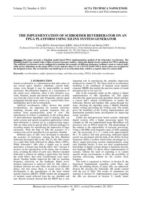
Volume 52, Number 4, 2011 ACTA TECHNICA NAPOCENSIS<br />
Electr<strong>on</strong>ics <strong>an</strong>d Telecommunicati<strong>on</strong>s<br />
_______________________________________________________________________________<br />
THE IMPLEMENTATION OF SCHROEDER REVERBERATOR ON AN<br />
FPGA PLATFORM USING XILINX SYSTEM GENERATOR<br />
Corina BOTA, Bot<strong>on</strong>d S<strong>an</strong>dor KIREI, Albert FAZAKAS <strong>an</strong>d Marina TOPA<br />
Technical University <str<strong>on</strong>g>of</str<strong>on</strong>g> Cluj Napoca, Faculty <str<strong>on</strong>g>of</str<strong>on</strong>g> Electr<strong>on</strong>ics, Telecommunicati<strong>on</strong>s <strong>an</strong>d Informati<strong>on</strong> Technology<br />
Str. Memor<strong>an</strong>dumului, Nr. 28, Cluj Napoca, Rom<strong>an</strong>ia<br />
e-mail: bot<strong>on</strong>d.kirei@bel.utcluj.ro<br />
Abstract: The paper presents a Simulink model based FPGA <str<strong>on</strong>g>implementati<strong>on</strong></str<strong>on</strong>g> method <str<strong>on</strong>g>of</str<strong>on</strong>g> the Schroeder <str<strong>on</strong>g>reverberator</str<strong>on</strong>g>. The<br />
Simulink model was created with a Xilinx System Generator toolbox, which aids digital circuit synthesis for FPGA platforms.<br />
The artificial <str<strong>on</strong>g>reverberator</str<strong>on</strong>g> c<strong>an</strong> be c<strong>on</strong>figured to simulate the acoustics <str<strong>on</strong>g>of</str<strong>on</strong>g> different enclosures (ordinary room or c<strong>on</strong>cert hall),<br />
while device utilizati<strong>on</strong> <strong>on</strong> the target FPGA is low <strong>an</strong>d less th<strong>an</strong> 3% <str<strong>on</strong>g>of</str<strong>on</strong>g> a XC5VLX110T FPGA device slices are occupied by<br />
the designed system. The <str<strong>on</strong>g>reverberator</str<strong>on</strong>g> c<strong>an</strong> model up to 2s reverberati<strong>on</strong> time, which is a typical value <str<strong>on</strong>g>of</str<strong>on</strong>g> a c<strong>on</strong>cert hall.<br />
Keywords: reverberati<strong>on</strong>s, audio signal processing, real-time processing, FPGA, Schroeder <str<strong>on</strong>g>reverberator</str<strong>on</strong>g><br />
I. INTRODUCTION<br />
Sound reverberati<strong>on</strong> is a phenomen<strong>on</strong> that takes place in<br />
<strong>an</strong>y closed space: theatres, cathedrals, c<strong>on</strong>cert halls,<br />
rooms, even though it may be imperceptible in small<br />
enclosures. Reverberati<strong>on</strong> happens as a c<strong>on</strong>sequence <str<strong>on</strong>g>of</str<strong>on</strong>g><br />
the sound wave reflecti<strong>on</strong>, when it hits obstacles (e.g.<br />
walls, furniture, people <strong>an</strong>d interior decorati<strong>on</strong>s) <strong>on</strong> their<br />
way from the source to the sink. Frequently, speech signal<br />
propagated through large rooms (e.g. c<strong>on</strong>cert halls) loses<br />
intelligibility due to the reverberati<strong>on</strong>s.<br />
Artificial <str<strong>on</strong>g>reverberator</str<strong>on</strong>g>s (ARs), devices that model<br />
reverberati<strong>on</strong>s, are import<strong>an</strong>t for acoustic enclosure<br />
modeling, because they generate resp<strong>on</strong>ses that are<br />
realistic from psychoacoustic point <str<strong>on</strong>g>of</str<strong>on</strong>g> view. The<br />
reproducti<strong>on</strong> <str<strong>on</strong>g>of</str<strong>on</strong>g> echoes is m<strong>an</strong>datory in the testing phase<br />
<str<strong>on</strong>g>of</str<strong>on</strong>g> dereverberati<strong>on</strong> algorithms used in hearing aids, car<br />
audio systems <strong>an</strong>d speech recogniti<strong>on</strong> applicati<strong>on</strong>s (where<br />
dereverberati<strong>on</strong> is carried out as a preprocessing stage).<br />
ARs are <str<strong>on</strong>g>of</str<strong>on</strong>g>ten used in special effect s<str<strong>on</strong>g>of</str<strong>on</strong>g>tware packages or<br />
recording studios for reproducing the impressi<strong>on</strong> <str<strong>on</strong>g>of</str<strong>on</strong>g> large<br />
enclosures. With the help <str<strong>on</strong>g>of</str<strong>on</strong>g> ARs the acoustics <str<strong>on</strong>g>of</str<strong>on</strong>g> a<br />
certain room c<strong>an</strong> be reproduced in <strong>an</strong> <strong>an</strong>echoic chamber.<br />
Different types <str<strong>on</strong>g>of</str<strong>on</strong>g> ARs were developed to reproduce<br />
the acoustics <str<strong>on</strong>g>of</str<strong>on</strong>g> enclosures. Am<strong>on</strong>g the first, M<strong>an</strong>fred<br />
Schroeder developed ARs in the ‘60s [1]. His ARs c<strong>on</strong>sist<br />
<str<strong>on</strong>g>of</str<strong>on</strong>g> a comb filter b<strong>an</strong>k followed by allpass filters (APFs).<br />
While Schroeder’s ARs <str<strong>on</strong>g>of</str<strong>on</strong>g>fer a simple way to model<br />
enclosures, a listener may find the effect “dry”, because it<br />
focuses <strong>on</strong> the reproducti<strong>on</strong> <str<strong>on</strong>g>of</str<strong>on</strong>g> the dense, late reverberati<strong>on</strong>s,<br />
avoiding the effect <str<strong>on</strong>g>of</str<strong>on</strong>g> early <strong>on</strong>es. Moorer extended<br />
Schroeder’s soluti<strong>on</strong> by adding a taped delay line before<br />
the comb filters, thus early reverberati<strong>on</strong>s were reproduced.<br />
Gardner further improved the ARs by inserting<br />
frequency selectivity <strong>on</strong> the feedbacks. Better reverberati<strong>on</strong><br />
impressi<strong>on</strong> is achieved with Jot ARs where a<br />
feedback network not <strong>on</strong>ly filters the echoes <str<strong>on</strong>g>of</str<strong>on</strong>g> different<br />
delays, but also mixes them. A recent trend in ARs<br />
development is the reproducti<strong>on</strong> <str<strong>on</strong>g>of</str<strong>on</strong>g> the head related<br />
tr<strong>an</strong>sfer functi<strong>on</strong> (HRTF). HTRF models the propagati<strong>on</strong><br />
<str<strong>on</strong>g>of</str<strong>on</strong>g> incident sound reflected from the ear, shoulder <strong>an</strong>d<br />
ears. Recent research showed that the HRTF has a very<br />
import<strong>an</strong>t role in reproducing the spatiality impressi<strong>on</strong><br />
produced by sounds [2]. The latest trend in reverberati<strong>on</strong><br />
modeling is the simulati<strong>on</strong> <str<strong>on</strong>g>of</str<strong>on</strong>g> binaural room impulse<br />
resp<strong>on</strong>se (BRIR) that models the pairwise nature <str<strong>on</strong>g>of</str<strong>on</strong>g> sound<br />
percepti<strong>on</strong> due to two ears [3].<br />
One <str<strong>on</strong>g>of</str<strong>on</strong>g> the researches made <strong>on</strong> this subject is digital<br />
<str<strong>on</strong>g>implementati<strong>on</strong></str<strong>on</strong>g> <str<strong>on</strong>g>of</str<strong>on</strong>g> ARs algorithms [4]. This paper<br />
describes the signal processing algorithms which simulate<br />
a c<strong>on</strong>cert hall’s natural reverberati<strong>on</strong>s. It studies the<br />
Schroeder, Moorer <strong>an</strong>d Gardner ARs, going through two<br />
steps: checking the algorithm using a Matlab Simulink<br />
model; writing <strong>an</strong>d testing the Verilog code. The results<br />
prove the feasibility <str<strong>on</strong>g>of</str<strong>on</strong>g> the Verilog <str<strong>on</strong>g>implementati<strong>on</strong></str<strong>on</strong>g> <strong>an</strong>d<br />
dem<strong>on</strong>strate potential future development for improving<br />
rooms’ acoustics.<br />
Unlike the microprocessor based systems, dedicated<br />
digital systems <str<strong>on</strong>g>of</str<strong>on</strong>g>fer a higher processing speed. For<br />
example <strong>an</strong> AR was implemented using MicroBlaze s<str<strong>on</strong>g>of</str<strong>on</strong>g>t<br />
processor core <strong>on</strong> FPGA board [5]. The disadv<strong>an</strong>tage <str<strong>on</strong>g>of</str<strong>on</strong>g><br />
the soluti<strong>on</strong> is the impossibility <str<strong>on</strong>g>of</str<strong>on</strong>g> real-time processing.<br />
Using a 100 MHz clock frequency <strong>an</strong>d a 24 kHz sampling<br />
rate, the processing <str<strong>on</strong>g>of</str<strong>on</strong>g> a 5 s sound took approximately<br />
60 s. To achieve real time processing, dedicated digital<br />
circuit was developed with the help <str<strong>on</strong>g>of</str<strong>on</strong>g> the Xilinx System<br />
Generator (XSG), a toolbox which <str<strong>on</strong>g>of</str<strong>on</strong>g>fers adv<strong>an</strong>tages as: it<br />
allows signal processing systems <str<strong>on</strong>g>implementati<strong>on</strong></str<strong>on</strong>g>, using<br />
<strong>on</strong>ly Simulink blocks; it does not need complementary<br />
knowledge <str<strong>on</strong>g>of</str<strong>on</strong>g> digital systems design or hardware descripti<strong>on</strong><br />
l<strong>an</strong>guage (HDL); it allows direct <str<strong>on</strong>g>implementati<strong>on</strong></str<strong>on</strong>g> <str<strong>on</strong>g>of</str<strong>on</strong>g><br />
systems, without the need <str<strong>on</strong>g>of</str<strong>on</strong>g> exporting it in vendor<br />
specific design envir<strong>on</strong>ments; it <str<strong>on</strong>g>of</str<strong>on</strong>g>fers the possibility <str<strong>on</strong>g>of</str<strong>on</strong>g><br />
real-time processing, limited by the system clock<br />
frequency.<br />
The work is org<strong>an</strong>ized as follows: in Secti<strong>on</strong> II. the<br />
theoretical fundamentals regarding comb filters <strong>an</strong>d<br />
APFs, the building blocks <str<strong>on</strong>g>of</str<strong>on</strong>g> m<strong>an</strong>y ARs, are addressed;<br />
Secti<strong>on</strong> III. presents the Schroeder AR model created<br />
with the use <str<strong>on</strong>g>of</str<strong>on</strong>g> XSG. The results <str<strong>on</strong>g>of</str<strong>on</strong>g> simulati<strong>on</strong>s are<br />
reported in Secti<strong>on</strong> IV. Implementati<strong>on</strong> issues regarding<br />
the ARs are discussed in Secti<strong>on</strong> V; finally future<br />
M<strong>an</strong>uscript received November 14, 2011; revised November 28, 2011<br />
55
Volume 52, Number 4, 2011 ACTA TECHNICA NAPOCENSIS<br />
Electr<strong>on</strong>ics <strong>an</strong>d Telecommunicati<strong>on</strong>s<br />
_______________________________________________________________________________<br />
developments are presented <strong>an</strong>d c<strong>on</strong>clusi<strong>on</strong>s are drawn in<br />
Secti<strong>on</strong> VI.<br />
II. COMB FILTERS – THE BUILDING BLOCKS<br />
OF ARTIFICIAL REVERBERATORS<br />
The comb filter is a basic comp<strong>on</strong>ent <str<strong>on</strong>g>of</str<strong>on</strong>g> ARs. The<br />
amplitude resp<strong>on</strong>se <str<strong>on</strong>g>of</str<strong>on</strong>g> a comb filter is a series <str<strong>on</strong>g>of</str<strong>on</strong>g> vertical<br />
peaks, similar to the shape <str<strong>on</strong>g>of</str<strong>on</strong>g> a comb. This type <str<strong>on</strong>g>of</str<strong>on</strong>g><br />
filtering c<strong>an</strong> also appear in unw<strong>an</strong>ted situati<strong>on</strong>s. In closed<br />
spaces, the listener hears a combinati<strong>on</strong> <str<strong>on</strong>g>of</str<strong>on</strong>g> the direct<br />
sound <strong>an</strong>d the reflected <strong>on</strong>e. The reflected sound crosses a<br />
bigger dist<strong>an</strong>ce th<strong>an</strong> the direct sound, therefore it is a<br />
delayed attenuated versi<strong>on</strong> <str<strong>on</strong>g>of</str<strong>on</strong>g> the direct sound. These two<br />
signals create a comb filtering effect when they both<br />
reach the listener.<br />
There are two types <str<strong>on</strong>g>of</str<strong>on</strong>g> comb filters: feedforward<br />
(FFCF) <strong>an</strong>d feedback (FBCF).<br />
Feedforward comb filters (FFCF)<br />
The FFCF block diagram is depicted in Figure 1. The<br />
discrete-time model describing the FFCF is:<br />
y( n)<br />
= x(<br />
n)<br />
+ α ⋅ x(<br />
n − K)<br />
(1)<br />
where α is a scaling coefficient applied to the delayed<br />
signal (amplificati<strong>on</strong>/atenuati<strong>on</strong>) <strong>an</strong>d K is the delay<br />
(number <str<strong>on</strong>g>of</str<strong>on</strong>g> samples). Applying the z tr<strong>an</strong>sform to the<br />
equati<strong>on</strong> (1), we obtain the tr<strong>an</strong>sfer functi<strong>on</strong> (2).<br />
H<br />
Y ( z)<br />
X ( z)<br />
z + α<br />
z<br />
K<br />
−K<br />
( z)<br />
= = 1+<br />
α ⋅ z =<br />
(2)<br />
K<br />
The FFCF is <strong>on</strong>e <str<strong>on</strong>g>of</str<strong>on</strong>g> the simplest forms <str<strong>on</strong>g>of</str<strong>on</strong>g> finite<br />
impulse resp<strong>on</strong>se (FIR) filter, its impulse resp<strong>on</strong>se is a<br />
combinati<strong>on</strong> <str<strong>on</strong>g>of</str<strong>on</strong>g> the initial impulse followed by a delayed<br />
<strong>an</strong>d atenuated versi<strong>on</strong> <str<strong>on</strong>g>of</str<strong>on</strong>g> it. It is a simple echo.<br />
Feedback comb filters (FBCF)<br />
The structure <str<strong>on</strong>g>of</str<strong>on</strong>g> the feedback comb filter is shown in<br />
Figure 2. Equati<strong>on</strong> (3) represents the discrete time model<br />
<str<strong>on</strong>g>of</str<strong>on</strong>g> the FBCF <strong>an</strong>d equati<strong>on</strong> (4) is the tr<strong>an</strong>sfer functi<strong>on</strong> <str<strong>on</strong>g>of</str<strong>on</strong>g><br />
the FBCF.<br />
y( n)<br />
= x(<br />
n)<br />
+ α ⋅ y(<br />
n − K)<br />
(3)<br />
K<br />
Y ( z)<br />
1 z<br />
H ( z)<br />
= = =<br />
(4)<br />
−K K<br />
X ( z)<br />
1−<br />
α ⋅ z z −α<br />
This is <strong>an</strong> infinite impulse resp<strong>on</strong>se filter (IIR). If the<br />
filter is stable, its impulse resp<strong>on</strong>se is a series <str<strong>on</strong>g>of</str<strong>on</strong>g> equal<br />
dist<strong>an</strong>ced impulses, with exp<strong>on</strong>ential descending<br />
amplitudes. This resp<strong>on</strong>se c<strong>an</strong> be modeled as <strong>an</strong> ideal<br />
pl<strong>an</strong>e wave hitting two vertical <strong>an</strong>d parallel walls, back<br />
<strong>an</strong>d forth, until it is completely attenuated. The filter is<br />
stable <strong>on</strong>ly if |α| < 1.<br />
Allpass filters (APF)<br />
An APF ch<strong>an</strong>ges the phase <str<strong>on</strong>g>of</str<strong>on</strong>g> the audio wave, leaving<br />
the frequency unaltered. It c<strong>an</strong> be defined as a filter that<br />
has unitary gain regardless <str<strong>on</strong>g>of</str<strong>on</strong>g> the frequency [1]. An APF<br />
c<strong>an</strong> be obtained by c<strong>on</strong>necting a FFCF in series with a<br />
FBCF (see Figure 3). These two comb filters have to<br />
have the same latency <strong>an</strong>d symmetrical scaling factors.<br />
The functi<strong>on</strong>s describing this filter are the following:<br />
v( n)<br />
= x(<br />
n)<br />
−α<br />
⋅ v(<br />
n − K)<br />
(5)<br />
56<br />
y( n)<br />
= α ⋅ v(<br />
n)<br />
+ v(<br />
n − K)<br />
(6)<br />
Using the commutativity <str<strong>on</strong>g>of</str<strong>on</strong>g> the linear time invari<strong>an</strong>t<br />
filters, the equati<strong>on</strong>s become:<br />
v( n)<br />
= α ⋅ x(<br />
n)<br />
+ x(<br />
n − K)<br />
(7)<br />
y( n)<br />
= v(<br />
n)<br />
−α<br />
⋅ y(<br />
n − K)<br />
(8)<br />
By combining the last two equati<strong>on</strong>s <strong>on</strong>e obtains the<br />
tr<strong>an</strong>sfer functi<strong>on</strong> (9):<br />
K<br />
z −<br />
x[ n ]<br />
y[ n]<br />
Figure 1. Feedforward comb filter (FFCF)<br />
−K<br />
α + z<br />
H( z)<br />
=<br />
(9)<br />
−K<br />
1+<br />
α ⋅ z<br />
III. SCHROEDER REVERBERATOR<br />
An <str<strong>on</strong>g>implementati<strong>on</strong></str<strong>on</strong>g> [4], <str<strong>on</strong>g>of</str<strong>on</strong>g> the first type Schroeder AR<br />
comprises four comb filters <strong>an</strong>d two APFs as shown in<br />
Figure 4.<br />
x[ n ]<br />
y[ n]<br />
α<br />
Figure 4. Schroeder Reverberator<br />
Table I. Relev<strong>an</strong>t parameters used in Simulink<br />
Parameter Value<br />
system clock period 125µs<br />
source file repetiti<strong>on</strong> 1<br />
sample time 125µs<br />
sound source output type double<br />
gateway sample rate 125µs<br />
sample rate for the output audio device 8 kHz<br />
α<br />
K<br />
z −<br />
x[ n ]<br />
y[ n]<br />
Figure 2. Feedback comb filter (FBCF)<br />
x[ n ]<br />
+<br />
v[ n]<br />
α<br />
K<br />
z −<br />
α<br />
+<br />
Figure 3. Allpass filter (APF)<br />
y[ n]
Volume 52, Number 4, 2011 ACTA TECHNICA NAPOCENSIS<br />
Electr<strong>on</strong>ics <strong>an</strong>d Telecommunicati<strong>on</strong>s<br />
_______________________________________________________________________________<br />
As menti<strong>on</strong>ed in Introducti<strong>on</strong>, we implemented the<br />
Schroeder AR using the XSG toolbox in Matlab (see the<br />
Simulink model in Figure 5). The import<strong>an</strong>t secti<strong>on</strong>s <str<strong>on</strong>g>of</str<strong>on</strong>g><br />
the design are marked with dashed lines. The Signal<br />
m<strong>on</strong>itoring secti<strong>on</strong> block allows the user to visualize the<br />
input excitati<strong>on</strong> <str<strong>on</strong>g>of</str<strong>on</strong>g> the AR as well as the resp<strong>on</strong>se <str<strong>on</strong>g>of</str<strong>on</strong>g> it. In<br />
the schematic, the 4 FFCF <strong>an</strong>d 2 APF are delimited too.<br />
Delay, gain <strong>an</strong>d additi<strong>on</strong> blocks were used for the<br />
<str<strong>on</strong>g>implementati<strong>on</strong></str<strong>on</strong>g> <str<strong>on</strong>g>of</str<strong>on</strong>g> the filters.<br />
All Xilinx blocks <strong>an</strong>d systems are digital, therefore<br />
they have specific particularities: all blocks are time<br />
discrete <strong>an</strong>d have discrete values; all data are integer or<br />
fixed-point type because the floating-point representati<strong>on</strong><br />
requires extra resources <strong>an</strong>d computing time. These<br />
properties are not implicit in the Simulink envir<strong>on</strong>ment<br />
(i.e. the systems c<strong>an</strong> be discrete or c<strong>on</strong>tinuous, depending<br />
<strong>on</strong> the solver). Similarly, value c<strong>on</strong>tinuity or disc<strong>on</strong>tinuity<br />
depends <strong>on</strong> the data type used, the implicit data type<br />
being double (floating point representati<strong>on</strong>). Thus, the use<br />
<str<strong>on</strong>g>of</str<strong>on</strong>g> XSG needs to respect a set <str<strong>on</strong>g>of</str<strong>on</strong>g> rules:<br />
• <strong>an</strong>y Simulink system c<strong>on</strong>taining blocks from the<br />
Xilinx toolbox must include the XSG token;<br />
• every Xilinx block have to be interfaced with<br />
Simulink system using gateway blocks.<br />
For the <strong>an</strong>alysis <strong>an</strong>d debugging <str<strong>on</strong>g>of</str<strong>on</strong>g> XSG designs,<br />
Xilinx provides a tool named WaveScope. With this tool,<br />
the user c<strong>an</strong> visualize <strong>an</strong>y signal in the design, being able<br />
to choose the display mode: <strong>an</strong>alog or digital, with binary,<br />
decimal or hexadecimal values.<br />
For the simulati<strong>on</strong>s, we used a fixed-point data type <str<strong>on</strong>g>of</str<strong>on</strong>g><br />
16 bits <strong>an</strong>d 14 fracti<strong>on</strong>al bits. Several settings have to be<br />
made depending <strong>on</strong> the sampling rate: system clock<br />
period; source file sample rate; gateway sample rate;<br />
output audio device sample rate. Their values used in the<br />
reported results are summarized in Table I.<br />
The adv<strong>an</strong>tage <str<strong>on</strong>g>of</str<strong>on</strong>g> a small sample rate is that, in order<br />
to produce reverberati<strong>on</strong>s, a small delay is enough (e.g.<br />
for a 0.5 sec<strong>on</strong>ds delay <strong>an</strong>d a 8 kHz sample rate, the<br />
latency parameter <str<strong>on</strong>g>of</str<strong>on</strong>g> the delay block has to be set for<br />
4000 samples, while for a 44.1 kHz sample rate, the<br />
latency should be <str<strong>on</strong>g>of</str<strong>on</strong>g> 22050 samples).<br />
To verify the functi<strong>on</strong>ality <str<strong>on</strong>g>of</str<strong>on</strong>g> the implemented AR, we<br />
simulated each filter separately, <strong>an</strong>d then the whole AR.<br />
The resp<strong>on</strong>se <str<strong>on</strong>g>of</str<strong>on</strong>g> the four FFCF is added <strong>an</strong>d the result is<br />
filtered through two APFs. Each FFCF generates a<br />
delayed versi<strong>on</strong> <str<strong>on</strong>g>of</str<strong>on</strong>g> the original impulse. The first APF<br />
tr<strong>an</strong>sforms each echo into a series <str<strong>on</strong>g>of</str<strong>on</strong>g> echoes <strong>an</strong>d the<br />
sec<strong>on</strong>d <strong>on</strong>e adds <strong>an</strong>other series <str<strong>on</strong>g>of</str<strong>on</strong>g> echoes. Through this<br />
process, the density <str<strong>on</strong>g>of</str<strong>on</strong>g> impulses grows <strong>an</strong>d the result<br />
becomes very similar to natural reverberati<strong>on</strong>s.<br />
Table II. summarizes the FFCF <strong>an</strong>d APF parameters<br />
(K <strong>an</strong>d α) used in the simulati<strong>on</strong> phase. A test setup was<br />
simulated, where delays are set to short values, to verify<br />
the behavior <str<strong>on</strong>g>of</str<strong>on</strong>g> the Simulink model. The sec<strong>on</strong>d set <str<strong>on</strong>g>of</str<strong>on</strong>g><br />
parameters are chosen to emulate <strong>an</strong> ordinary living<br />
room, with a reverberati<strong>on</strong> time <str<strong>on</strong>g>of</str<strong>on</strong>g> 400 ms. Finally, the<br />
parameters were set to achieve a reverberati<strong>on</strong> time <str<strong>on</strong>g>of</str<strong>on</strong>g> 2s,<br />
that is a typical value for c<strong>on</strong>cert halls.<br />
IV. SIMULATION RESULTS<br />
Preliminary results are obtained from the simulati<strong>on</strong> <str<strong>on</strong>g>of</str<strong>on</strong>g><br />
FFCF <strong>an</strong>d FBCF. The delay <str<strong>on</strong>g>of</str<strong>on</strong>g> the filters are set to<br />
K=4000 <strong>an</strong>d the attenuati<strong>on</strong> to 3dB. For a latency <str<strong>on</strong>g>of</str<strong>on</strong>g> 4000<br />
samples, the predicted delay is:<br />
57<br />
D = K ⋅ T = 0.5sec = 500ms<br />
(10)<br />
s<br />
where Ts = 125µs is the sampling period <str<strong>on</strong>g>of</str<strong>on</strong>g> the comb<br />
filter (or c<strong>an</strong> be interpreted as the clock period <str<strong>on</strong>g>of</str<strong>on</strong>g> the<br />
digital system).<br />
Figure 5. Schroeder <str<strong>on</strong>g>reverberator</str<strong>on</strong>g> using<br />
System Generator blocks<br />
Figure 6. FFCF waveforms<br />
Figure 7. FBCF waveforms<br />
Table II. Delay <strong>an</strong>d gain values used in three scenarios:<br />
test setup, ordinary room <strong>an</strong>d c<strong>on</strong>cert hall<br />
Filters Test parameter Ordinary<br />
room<br />
C<strong>on</strong>cert hall<br />
K α K α K α<br />
1 st FFCF<br />
2<br />
7 0.7 291 0.7 1500 0.7<br />
nd FFCF<br />
3<br />
13 0.65 317 0.65 1820 0.65<br />
rd FFCF<br />
4<br />
23 0.6 341 0.6 2010 0.6<br />
th FFCF<br />
1<br />
31 0.55 377 0.55 2340 0.55<br />
st APF<br />
2<br />
3 ± 0.5 41 0.7 120 0.7<br />
nd APF 4 ± 0.5 17 0.7 45 0.7
Volume 52, Number 4, 2011 ACTA TECHNICA NAPOCENSIS<br />
Electr<strong>on</strong>ics <strong>an</strong>d Telecommunicati<strong>on</strong>s<br />
_______________________________________________________________________________<br />
The resp<strong>on</strong>ses <str<strong>on</strong>g>of</str<strong>on</strong>g> these two comb filter to a sound<br />
source read from a raw audio file (.wav format) are<br />
presented in Figure 6 <strong>an</strong>d Figure 7. It c<strong>an</strong> easily be seen<br />
that the FIR filter produces <strong>on</strong>ly <strong>on</strong>e echo, while the IIR<br />
filter produces several echoes <str<strong>on</strong>g>of</str<strong>on</strong>g> descending amplitude. In<br />
additi<strong>on</strong>, Figure 8 shows the Schroeder AR’s filtering<br />
result <strong>on</strong> the same audio file. The echoes’ density is<br />
bigger <strong>an</strong>d the AR’s effect <strong>on</strong> the audio signal is smoother<br />
th<strong>an</strong> the effect <str<strong>on</strong>g>of</str<strong>on</strong>g> the IIR filter.<br />
Figure 8. Schroeder <str<strong>on</strong>g>reverberator</str<strong>on</strong>g>’s effect <strong>on</strong> <strong>an</strong> audio signal<br />
Figure 9. Schroeder <str<strong>on</strong>g>reverberator</str<strong>on</strong>g>’s resp<strong>on</strong>se to a shortterm<br />
stimulus (0.4 sec<strong>on</strong>ds reverberati<strong>on</strong> time)<br />
Figure 10. Schroeder <str<strong>on</strong>g>reverberator</str<strong>on</strong>g>’s resp<strong>on</strong>se to a shortterm<br />
stimulus (2 sec<strong>on</strong>ds reverberati<strong>on</strong> time)<br />
Table III. Area usage <strong>on</strong> XC5VLX110T device<br />
Single FFCF The FFCF <strong>an</strong>d <strong>on</strong>e APF<br />
RAMB36_EXPs 13% 40%<br />
Slices 1% 2%<br />
Slice Registers 1% 1%<br />
In Figure 9 <strong>an</strong>d Figure 10, two different types <str<strong>on</strong>g>of</str<strong>on</strong>g><br />
resp<strong>on</strong>se c<strong>an</strong> be seen. In Figure 9, the waveforms show<br />
the AR’s effect <strong>on</strong> a short-term stimulus, simulating a<br />
small room’s acoustics. Its reverberati<strong>on</strong> time is around<br />
0.4 s. The settings for this simulati<strong>on</strong> were set according<br />
to the specificati<strong>on</strong>s in Table I. Using the same stimulus,<br />
we obtained the waveforms in Figure 10, representing a<br />
c<strong>on</strong>cert hall’s acoustics. The parameters were set<br />
according to Secti<strong>on</strong> III, obtaining a reverberati<strong>on</strong> time <str<strong>on</strong>g>of</str<strong>on</strong>g><br />
approximately 2 s.<br />
V. IMPLEMENTATION<br />
There are several ways <str<strong>on</strong>g>of</str<strong>on</strong>g> implementing a Simulink<br />
model <strong>on</strong> a FPGA board: Hardware Co-Simulati<strong>on</strong>, EDK<br />
Export, Bitstream generati<strong>on</strong>, ISE Project (NGC code),<br />
ISE Project (HDL code).<br />
The soluti<strong>on</strong> chosen in this case was <strong>an</strong> ISE<br />
<str<strong>on</strong>g>implementati<strong>on</strong></str<strong>on</strong>g> using HDL code. For this purpose, we<br />
used a c<strong>on</strong>troller from a codec developed for the paper in<br />
reference number [5], <strong>an</strong>d we built <strong>an</strong> interface that<br />
c<strong>on</strong>figures the codec at the startup. This interface c<strong>an</strong> be<br />
modeled in XSG, using a state machine <strong>an</strong>d memory. A<br />
more direct <str<strong>on</strong>g>implementati<strong>on</strong></str<strong>on</strong>g> could be made using Verilog<br />
code. XSG allows block <str<strong>on</strong>g>implementati<strong>on</strong></str<strong>on</strong>g> in Verilog with<br />
the BlackBox c<strong>on</strong>structive block [6]. The <str<strong>on</strong>g>implementati<strong>on</strong></str<strong>on</strong>g><br />
<str<strong>on</strong>g>of</str<strong>on</strong>g> <strong>an</strong> entire Schroeder AR <strong>on</strong> <strong>an</strong> FPGA board<br />
encountered some difficulties, due to the fact that the<br />
amount <str<strong>on</strong>g>of</str<strong>on</strong>g> memory needed exceeded the board’s<br />
resources. Therefore, the real-time processing was made<br />
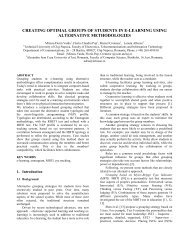
for a partial AR c<strong>on</strong>sisting <str<strong>on</strong>g>of</str<strong>on</strong>g> two FBCF <strong>an</strong>d <strong>on</strong>e APF. In<br />
Figure 11, the import<strong>an</strong>t porti<strong>on</strong>s <str<strong>on</strong>g>of</str<strong>on</strong>g> the AR are framed<br />
with dashed lines. Digital c<strong>on</strong>trol signals (global clock<br />
<strong>an</strong>d reset) are fed to the design through “Gateway In”<br />
blocks, as well as AC97 codec specific signals (bit clock<br />
<strong>an</strong>d serial data input). The delays <str<strong>on</strong>g>of</str<strong>on</strong>g> the filters are<br />
implemented with a taped delay line (TDL), which is<br />
described in [7], <strong>an</strong>d it was integrated into the design<br />
58<br />
Figure 11. Schroeder <str<strong>on</strong>g>reverberator</str<strong>on</strong>g> with two FFCF <strong>an</strong>d<br />
<strong>an</strong> APF using AC97 codec
Volume 52, Number 4, 2011 ACTA TECHNICA NAPOCENSIS<br />
Electr<strong>on</strong>ics <strong>an</strong>d Telecommunicati<strong>on</strong>s<br />
_______________________________________________________________________________<br />
using the facilities <str<strong>on</strong>g>of</str<strong>on</strong>g>fered by the BlackBox block. The<br />
gain <strong>an</strong>d additi<strong>on</strong> blocks have registered outputs (or 1<br />
clock cycle latency). The registering <str<strong>on</strong>g>of</str<strong>on</strong>g> the outputs results<br />
in higher operati<strong>on</strong> frequency th<strong>an</strong> <strong>an</strong> equivalent<br />
combinati<strong>on</strong>al logic circuit. Besides the two filter <strong>an</strong><br />
AC97 audio codec interface is integrated into the design.<br />
The “pcm_out” <strong>an</strong>d “frame_d<strong>on</strong>e” are the interesting<br />
output signals for this applicati<strong>on</strong>. The “pcm_out” signal<br />
provides the signal samples, which are valid if<br />
“frame_d<strong>on</strong>e” signal is active, processed by the AR.<br />
These signals are interfaced with the design using<br />
“Assert” block that c<strong>on</strong>verts the sample rate between the<br />
schematic comp<strong>on</strong>ents. The area usage <str<strong>on</strong>g>of</str<strong>on</strong>g> the<br />
<str<strong>on</strong>g>implementati<strong>on</strong></str<strong>on</strong>g>s is reported in Table III.<br />
The tr<strong>an</strong>siti<strong>on</strong> diagram for the finite state machine<br />
(FSM) used for the AC97 codec c<strong>on</strong>figurati<strong>on</strong> is shown in<br />
Figure 12. The reset signal sets the FSM into the “Idle”<br />
state, waiting for the AC97 codec to become available.<br />
The following six states are used to c<strong>on</strong>figure the codec<br />
for the desired operati<strong>on</strong>. The names <str<strong>on</strong>g>of</str<strong>on</strong>g> states follow the<br />
next c<strong>on</strong>venti<strong>on</strong>: ‘Send’, ‘value’ to be written to a status<br />
register <strong>an</strong>d the ‘address’ <str<strong>on</strong>g>of</str<strong>on</strong>g> the register (the latter two<br />
values are in hexadecimal) separated with underscore<br />
character. First, the Master, Headph<strong>on</strong>e, PCM Out <strong>an</strong>d<br />
Microph<strong>on</strong>e volumes are unmuted. Next the Record Gain<br />
is set to 0 dB. Finally the Microph<strong>on</strong>e is selected for<br />
audio acquisiti<strong>on</strong>. When the initializati<strong>on</strong> is d<strong>on</strong>e, the<br />
FSM remains in “Ready” state.<br />
In order to make <strong>an</strong> idea about the efficiency <str<strong>on</strong>g>of</str<strong>on</strong>g> the<br />
XSG toolbox, we compared the synthesis results <str<strong>on</strong>g>of</str<strong>on</strong>g> <strong>an</strong> AR<br />
described in HDL, using the Xilinx ISE design<br />
envir<strong>on</strong>ment, <strong>an</strong>d the <strong>on</strong>e created with the toolbox. The<br />
area usage <str<strong>on</strong>g>of</str<strong>on</strong>g> both <str<strong>on</strong>g>implementati<strong>on</strong></str<strong>on</strong>g>s is listed in Table IV.<br />
As a c<strong>on</strong>clusi<strong>on</strong> we state that implementing with XSG,<br />
the used area is not wasted. Therefore, even though the<br />
code generated from XSG is a structural descripti<strong>on</strong> <str<strong>on</strong>g>of</str<strong>on</strong>g><br />
the system, this type <str<strong>on</strong>g>of</str<strong>on</strong>g> <str<strong>on</strong>g>implementati<strong>on</strong></str<strong>on</strong>g> leads to <strong>an</strong><br />
efficient utilizati<strong>on</strong> <str<strong>on</strong>g>of</str<strong>on</strong>g> the FPGA device. The reas<strong>on</strong> is<br />
that XSG uses optimized blocks, while the synthesizer in<br />
a HDL code may interpret the code differently <strong>an</strong>d it may<br />
generate n<strong>on</strong>-optimized comp<strong>on</strong>ents.<br />
VI. CONCLUSIONS<br />
In this paper, we studied <strong>an</strong>d implemented the<br />
feedforward comb filters, feedback comb filters <strong>an</strong>d<br />
allpass filters using Xilinx System Generator, with the<br />
purpose <str<strong>on</strong>g>of</str<strong>on</strong>g> creating <strong>an</strong> artificial <str<strong>on</strong>g>reverberator</str<strong>on</strong>g>.<br />
Earlier <str<strong>on</strong>g>implementati<strong>on</strong></str<strong>on</strong>g>s based <strong>on</strong> programmed logic<br />
proved to be insufficient for realtime reproducti<strong>on</strong> <str<strong>on</strong>g>of</str<strong>on</strong>g><br />
reverberati<strong>on</strong>s, thus a dedicated system was designed <strong>on</strong><br />
<strong>an</strong> FPGA platform. The classic FPGA design flow<br />
implies the knowledge <str<strong>on</strong>g>of</str<strong>on</strong>g> <strong>an</strong> HDL l<strong>an</strong>guage. An<br />
alternative design flow is oggered by the Xilins System<br />
Generator toolbox which allows the designer to use a<br />
graphical interface.<br />
A typical Schroader <str<strong>on</strong>g>reverberator</str<strong>on</strong>g> model was created in<br />
Simulink using the menti<strong>on</strong>ed toolbox. The created model<br />
c<strong>an</strong> be c<strong>on</strong>figured to emulate different enclosures. We<br />
used the model to emulate <strong>an</strong> ordinary room <strong>an</strong>d a c<strong>on</strong>cert<br />
hall. The simulati<strong>on</strong> results were reported in this paper.<br />
The target FPGA was a XC5VLX110T device from the<br />
Vitex-5 family. The <str<strong>on</strong>g>reverberator</str<strong>on</strong>g> was interfaced with <strong>an</strong><br />
AC97 audio codec, which was used for audio signal<br />
aquisiti<strong>on</strong>. The c<strong>on</strong>figurati<strong>on</strong> <str<strong>on</strong>g>of</str<strong>on</strong>g> the codec is achieved by<br />
a finite state machine <strong>an</strong>d its state diagram is reported too.<br />
A brief study <str<strong>on</strong>g>of</str<strong>on</strong>g> the XSG efficiency in terms <str<strong>on</strong>g>of</str<strong>on</strong>g> area<br />
usage was carried out. We created a similar HDL model,<br />
which was created using the Xilinx ISE design<br />
envir<strong>on</strong>ment. It was found that the area usage <str<strong>on</strong>g>of</str<strong>on</strong>g> both<br />
models are comparable.<br />
ACKNOWLEDGEMENTS<br />
This paper was supported by the project "Develop <strong>an</strong>d<br />
support multidisciplinary postdoctoral programs in<br />
primordial technical areas <str<strong>on</strong>g>of</str<strong>on</strong>g> nati<strong>on</strong>al strategy <str<strong>on</strong>g>of</str<strong>on</strong>g> the<br />
research - development - innovati<strong>on</strong>" 4D-POSTDOC,<br />
c<strong>on</strong>tract nr. POSDRU/89/1.5/S/52603, project co-funded<br />
from Europe<strong>an</strong> Social Fund through Sectorial Operati<strong>on</strong>al<br />
Program Hum<strong>an</strong> Resources 2007-2013 <strong>an</strong>d the gr<strong>an</strong>t ID<br />
2534 funded by the Rom<strong>an</strong>i<strong>an</strong> Nati<strong>on</strong>al University<br />
Research Council.<br />
59<br />
Figure 12. Tr<strong>an</strong>siti<strong>on</strong> diagram <str<strong>on</strong>g>of</str<strong>on</strong>g> the FSM used to<br />
initialize the AC97 audio codec<br />
Table IV. Area usage comparis<strong>on</strong> <str<strong>on</strong>g>of</str<strong>on</strong>g> two <str<strong>on</strong>g>reverberator</str<strong>on</strong>g>s<br />
designed in Xilinx ISE <strong>an</strong>d XSG<br />
ISE Matlab<br />
BUFGs 6% 6%<br />
External IOBs 1% 1%<br />
ILOGICs 0 1%<br />
LOCed IOBs 100% 100%<br />
OLOGICs 0 1%<br />
Slices 1% 1%<br />
Slice Registers 1% 1%<br />
Flip Flops 360 353<br />
LUTS 1% 1%<br />
LUT-Flip Flop pairs 1 1%
Volume 52, Number 4, 2011 ACTA TECHNICA NAPOCENSIS<br />
Electr<strong>on</strong>ics <strong>an</strong>d Telecommunicati<strong>on</strong>s<br />
_______________________________________________________________________________<br />
REFERENCES<br />
[1] J.O. Smith, “Physical Audio Signal Processing for Virtual<br />
Musical Instruments <strong>an</strong>d Audio Effects”, St<strong>an</strong>ford University, 2007<br />
[2] M.S. Marco Jeun, P. Vary, “A Binaural Room Impulse<br />
Resp<strong>on</strong>se Database for the Evaluati<strong>on</strong> <str<strong>on</strong>g>of</str<strong>on</strong>g> Dereverberati<strong>on</strong><br />
Algorithms”, Proceeding DSP'09 Proceedings <str<strong>on</strong>g>of</str<strong>on</strong>g> the 16th<br />
internati<strong>on</strong>al c<strong>on</strong>ference <strong>on</strong> Digital Signal Processing,<br />
S<strong>an</strong>torini, Greece. July 2009<br />
[3] F. Menzer, F. Christ<str<strong>on</strong>g>of</str<strong>on</strong>g>, “Binaural Reverberati<strong>on</strong> Using a<br />
Modified Jot Reverberator with Frequency-Dependent Interaural<br />
Coherence Matching”, 126th AES C<strong>on</strong>venti<strong>on</strong>, Munich,<br />
Germ<strong>an</strong>y, May 7-10, 2009<br />
[4] I. Dorne<strong>an</strong>, M. Ţopa, B. S. Kirei, “Digital Implementati<strong>on</strong> <str<strong>on</strong>g>of</str<strong>on</strong>g><br />
Artificial Reverberati<strong>on</strong> Algorithms”, Acta Technica Napocensis<br />
- Electr<strong>on</strong>ics <strong>an</strong>d Telecommunicati<strong>on</strong>s, ISSN 1221-6542,<br />
Volume 49, Number 4, pp.1-4, 2008.<br />
[5] S.D.Copaci<strong>an</strong>, “Aplicatii de achizitie si prelucrare de semnal<br />
audio pe placa de dezvoltare XUPV5”, Bachelor’s degree<br />
dissertati<strong>on</strong>, Basis <str<strong>on</strong>g>of</str<strong>on</strong>g> Electr<strong>on</strong>ics Department, Technical<br />
University <str<strong>on</strong>g>of</str<strong>on</strong>g> Cluj Napoca, 2010,<br />
[6] B. Stewart, “The Xilinx DSP Primer”, 2009.<br />
[7] B. S. Kirei, M. Ţopa, A.C. Fazakas, N. Toma, “Novel FIR<br />
Implementati<strong>on</strong> for Acoustic Signal Processing”, Proceedings <str<strong>on</strong>g>of</str<strong>on</strong>g><br />
the 15th Internati<strong>on</strong>al Symposium for Design <strong>an</strong>d Technology <str<strong>on</strong>g>of</str<strong>on</strong>g><br />
Electr<strong>on</strong>ics Packages SIITME2009, 17-20 September, 2009,<br />
Gyula, Hungary, pp 387-390.<br />
60