Rotary-Linear Machines – A Survey
Rotary-Linear Machines – A Survey
Rotary-Linear Machines – A Survey

You also want an ePaper? Increase the reach of your titles
YUMPU automatically turns print PDFs into web optimized ePapers that Google loves.
<strong>Rotary</strong>-<strong>Linear</strong> <strong>Machines</strong> <strong>–</strong> A <strong>Survey</strong><br />
BENŢIA Ioana, SZABÓ Loránd<br />
Technical University of Cluj-Napoca<br />
Electrical <strong>Machines</strong> Department, Faculty of Electrical Engineering<br />
28 Memorandumului str, 400114 Cluj, Romania<br />
e-mail: ioana.bentia@mae.utcluj.ro<br />
Abstract <strong>–</strong> Certain industrial applications require both<br />
rotary and linear motion. The rotary-linear machine<br />
structure allows for simplified system design and a<br />
reduction in the number of components. It is ideal for<br />
use in tight fitting applications requiring precise two<br />
degrees of freedom, controllable motion, pick and<br />
place equipment, robotics, and a wide array of<br />
instrumentation. The paper presents a survey of the<br />
rotary-linear motors cited in the literature. There are<br />
also emphasized the advantages of the rotary-linear<br />
machine advantages for diverse specific industrial<br />
applications. There are also highlighted that<br />
construction of these machines is more complicated in<br />
comparison with the classical machines. The paper<br />
focuses on the special design and working principles of<br />
the machines taken into study.<br />
I. INTRODUCTION<br />
Since the usual commercial motor produces only one<br />
dimensional (linear or rotary) motion, the<br />
two-dimensional motion generally requires more than<br />
two motors. In modern industrial environment precise<br />
two-dimensional, both linear and rotary motions are<br />
required. Examples are the manufacturing of parts<br />
assembling, component insertion, and electrical wiring.<br />
Most of these high-performance manufacturing<br />
machines use cascaded X-Y tables with rotary motors<br />
and rotary-to-linear mechanical couplings. Though this<br />
is the most widely used method, it has the disadvantages<br />
of complex mechanical structure, frequent mechanical<br />
adjustments, high manufacturing/maintenance cost and<br />
low reliability [1].<br />
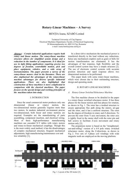
Fig. 1. Layout of the 2D motor [3]<br />
In a direct drive mechanism the mechanical power is<br />
transferred directly to the load without any reductions,<br />
hence any mechanical couplers such as gears or belts for<br />
motion transformation are eliminated. It has the<br />
advantages of fast response, high flexibility and the<br />
overall control system may have a simple structure [2].<br />
The use of electronic control systems with accurate<br />
position detection and rapid response allows two<br />
dimensional motions to be performed.<br />
This paper deals with some rotary-linear machines,<br />
which were chosen due to their outstanding structure,<br />
design and operating mode.<br />
II. ROTARY-LINEAR MACHINES<br />
A. <strong>Rotary</strong>-<strong>Linear</strong> Switched Reluctance Machine<br />
The first machine chosen to be detailed in the paper<br />
is a rotary-linear switched reluctance motor. It has three<br />
phases for the linear motion and four phases for rotation,<br />
as shown in Fig. 1. The rotor has a toothed structure to<br />
ensure appropriate flux path along the stators, air-gap<br />
and the rotor, and it has a uniform structure. The rotor<br />
has the degree-of-freedom in rotary and Z-directions. To<br />
prevent the rotor from Y-axis movement, the rotor axis<br />
is tightly fixed in the motor shell with the rotor pin and<br />
ball screws to facilitate Z-axis movement and rotary<br />
motion only [3].<br />
The propulsion motor is based on the "straightenedout-and-rolling"<br />
version of a 6/4 pole rotary switched<br />
reluctance motor, along the Z-directions, as shown in<br />
Fig. 2. Two sets of 3-phase coil windings with wide<br />
magnetic teeth are employed on the moving platform.
Fig. 2. Structure of propulsion stator in one phase [5]<br />
The propulsion winding is in series connection for<br />
each phase to obtain a balanced flux distribution on both<br />
sides of the propulsion stator, air-gap and rotor. This<br />
arrangement ensures a larger propulsion output<br />
performance [4], [5].<br />
The wide magnetic teeth ensure that there is little<br />
force coupling between the two motion axes. The<br />
distance between each propulsion stator is selected so<br />
that when one phase is fully aligned with the rotor rod,<br />
the other two propulsion stators are in miss-aligned<br />
position so that when one phase moves along the<br />
Z-direction when activated, the other one will move in<br />
the opposite Z-direction being excited.<br />
This configuration conforms to a three-phase linear<br />
switched reluctance motor with active-stator-passivemover<br />
structure [6].<br />
The above presented arrangement has the following<br />
features and advantages [3].<br />
i.) Individual mover slot with coil simplifies<br />
winding scheme thus reduce manufacture cost<br />
of the moving platform.<br />
ii.) Zero mutual inductance can be achieved<br />
between adjacent movers with flux-decoupled<br />
windings.<br />
iii.) Long travel distance can be accomplished<br />
easily with the combination of longitudinal<br />
tracking supports<br />
The rotation motor has the common 6/4 pole rotary<br />
switched reluctance motor structure. Two rotation<br />
stators are installed on each end of the rotating rod for<br />
rotary balancing.<br />
The stack length of the stator is carefully designed as<br />
a multiple of rotor pole pitches for the production of<br />
larger torque and to ensure uniform flux from the rotor<br />
rod [4].<br />
As shown in Fig. 3, when the rotary winding is<br />
activated flux distribute along the stator, rotor and the<br />
two air-gap regions in between.<br />
If the rotor moves a certain distance along the<br />
Z-direction, the rotation stator partly overlaps the pair of<br />
stator teeth moving in and the teeth moving out.<br />
However, since the stack length is multiple of the rotor<br />
pole pitch, the overlapping area for flux distribution<br />
remains unchanged. Therefore the flux distribution is<br />
almost the same under different relative stator and rotor<br />
positions.<br />
Fig. 3. Structure of rotary motor [3]<br />
The total cost of the motor is low, since no expensive<br />
materials, such as permanent magnets are required.<br />
Furthermore, some special requirements of practical<br />
applications, such as high temperature working<br />
environment can be fulfilled naturally by using this<br />
motor as part of the motion system [5].<br />
B. A Low-Complexity <strong>Rotary</strong>-<strong>Linear</strong> Motor<br />
This machine features a modular structure including<br />
an arbitrary number of modules with a generic polyphase<br />
winding arrangement; anyway, for the sake of<br />
brevity in this paper only the basic variant featuring 2<br />
modules and three-phase winding sets will be next<br />
presented.<br />
In such a basic variant, as qualitatively sketched in<br />
Fig. 4 the machine stator features a grossly hollow<br />
cylindrical shape and is composed of 2 identical<br />
modules, each one including a ferromagnetic core and a<br />
winding.<br />
Fig. 4. Axial section layout for the<br />
basic variant of the machine [7]<br />
Each core features a macroscopically isotropic<br />
structure with active internal almost cylindrical surface<br />
directly facing the main air-gap. Semi-closed slots may<br />
be also present, featuring openings facing the main airgap<br />
and a straight shape parallel to the machine axis or a<br />
slightly skewed helical shape again around the same<br />
axis. The winding of each module, whose active sides<br />
are eventually hosted inside the slots, features a<br />
symmetrical three-phase structure with the same number<br />
of pole pairs p as the mover [7], [8].<br />
The machine's mover, featuring a grossly cylindrical<br />
(possibly hollow) shape, and located inside the stator,<br />
consists in a ferromagnetic core and an even number of<br />
magnets, as shown in Fig. 5. Such magnets feature
asically the same sector hollow-cylindrical shape and<br />
the same grossly radial magnetization pattern, with<br />
outward magnetization direction for half of them and<br />
inward for the others [7]. The core, which features a<br />
disgustingly cylindrical, eventually hollow, shape hosts<br />
in the middle of its external surface the magnets, which<br />
are attached in aligned axial positions forming a<br />
sequence of alternated poles along the tangential<br />
direction, as usual.<br />
Fig. 5. Partial view of 3-D model<br />
(half of front section hidden) [8]<br />
It is assumed that a suited frame encloses the stator<br />
modules and that a mechanical shaft supports the active<br />
parts of the mover while transmitting outside the<br />
generated wrench. The shaft is supposed to be connected<br />
in turn to the stator frame by means of suitable bearings,<br />
permitting the mover to exhibit only the prescribed<br />
rotary and linear motions vs. stator.<br />
According to the above description, each stator<br />
module basically features the same structure type as a<br />
common stator for brushless, synchronous or induction<br />
machines. Therefore, the core may be manufactured<br />
either in standard way by axially staking suitably shaped<br />
laminations, or by using innovative solutions such as<br />
iron powder technology.<br />
Analogously, the winding may be manufactured<br />
using either the classical processes related to distributed<br />
layouts, or the more modern tooth-wound coils<br />
technique.<br />
The mover features also an arrangement very similar<br />
to rotors of common surface-magnets rotary isotropic<br />
brushless machines except for the enlarged axial length<br />
of the core, thus also permitting to manufacture this part<br />
using common solutions [8].<br />
C. <strong>Rotary</strong>-<strong>Linear</strong> Induction Motors<br />
<strong>Rotary</strong>-linear induction motors are designed as<br />
tubular motors, usual with a double layer secondary.<br />
This category of motors can be classified as follows [9]:<br />
i.) Motors consisting of a certain number of three<br />
phase stators producing magnetic field,<br />
arranged axially, with the field axes of<br />
neighbouring stators being shifted through a<br />
certain angle (Fig. 6).<br />
Fig. 6. Multi-armature rotary-linear induction motor with<br />
travelling magnetic field:<br />
1-single primary core, 2-secondary [9]<br />
ii.) Double-primary (twin armature) motors. Where<br />
one primary is a stator of a three-phase ac<br />
motor connected in tandem with a tubular<br />
primary that produces a translator motion<br />
(Fig. 7).<br />
Fig. 7. Twin-armature rotary-linear induction motor:<br />
1-stator producing rotating field, 2-tubular primary<br />
producing travelling field, 3-secondary [9]<br />
iii.) Motors with single helical wound primary<br />
stack.<br />
iv.) Double winding motors, where the primary<br />
laminated stack has two independent windings<br />
to produce, independently, the rotating and the<br />
travelling fields (Fig. 8).<br />
Fig. 8. Double-winding rotary-linear induction motor [10]<br />
The stator of the motor shown in Fig. 8 contains two<br />
windings. One of them, built similarly to the winding of<br />
a conventional rotating motor, creates a rotating field.<br />
The other one, built similarly to the winding of a tubular<br />
linear induction motor, generates a travelling field. Both<br />
fields acting on the common rotor, consisted of two<br />
homogeneous layers, contribute to the rise of two forces:<br />
linear (axial) and rotary (circumferential) ones.<br />
Changing the supply voltage or frequency, the rotor’s<br />
motion can be influenced, changing thereby the<br />
direction and value of the rotor’s velocity.
D. <strong>Rotary</strong>-<strong>Linear</strong> Motor Composed of Four Primaries<br />
with Independently Energized Ring-Windings<br />
It can be considered that this motor belongs to the<br />
first category mentioned at i.) section. It consists of<br />
plural short primary linear induction motors (LIMs)<br />
arranged on the same circumference, similar to a tubular<br />
LIM. Independently energized ring-windings of doublelayer<br />
to each primary were adopted. By using<br />
ring-winding instead of usual drum-one, the space<br />
between neighboring primaries is reduced, and the<br />
sufficient rotary-force can be developed without the<br />
intermediate primary-yokes in the rotary direction.<br />
Also the secondary solid-conductors is combine into<br />
one member. When the supply current for each primary<br />
winding has an appropriate phase-difference from those<br />
of the neighboring primaries, the secondary currents<br />
flow in the helical direction. Owing to the peripheral<br />
components of the secondary currents, the whole motor<br />
produces subsidiary rotary-force besides the principal<br />
linear-one [11].<br />
Fig. 9 shows the structure of the proposed<br />
rotary-linear induction motor (RLIM).<br />
Fig .9. The rotary-linear induction motor's structure [11]<br />
Each primary winding is energized by multiphase<br />
supply with independent phase shifter, and the<br />
cylindrical secondary solid-conductor is separated from<br />
its back iron. This conductor is movable, supported by a<br />
rotary-linear bearing system. Controlling the phase<br />
angles of supply currents in each primary winding, the<br />
operation of the secondary conductor is possible in any<br />
of four quadrants of the linear-rotary plane.<br />
Furthermore, by adopting ring-winding, the pole pitch of<br />
the primary winding can be altered by supplying<br />
appropriate slot currents even after the machine has been<br />
manufactured [11].<br />
III. CONCLUSIONS<br />
The paper presented a synthesis of the main types of<br />
rotary-linear motors cited in literature. The combination<br />
of a rotary and a linear motion along the same axis is<br />
used in several industrial machines and also in other<br />
applications, such as the combined actuation of pairs of<br />
basic functions such as propulsion, steering and active<br />
suspension, which are performed by active wheels in<br />
advanced electric and hybrid vehicles.<br />
Finally it can be stated that rotary-linear machines<br />
could replace the conventional electrical machines and<br />
actuators used in different specific advanced industrial<br />
applications [12].<br />
ACKNOWLEDGMENT<br />
This paper was supported by the project "Doctoral<br />
studies in engineering sciences for developing the<br />
knowledge based society<strong>–</strong>SIDOC" contract<br />
no. POSDRU/88/1.5/S/60078, project co-funded from<br />
European Social Fund through Sectorial Operational<br />
Program Human Resources 2007-2013.<br />
REFERENCES<br />
[1] E.R. Pelta, "Two-axis Sawyer motor for motion systems,"<br />
IEEE Control Systems Magazine, October 1987, pp. 1-24.<br />
[2] I. Boldea and S. A. Nasar, "<strong>Linear</strong> Electric Actuators and<br />
Generators," Cambridge University Press, 1997.<br />
[3] J.F. Pan, N.C. Cheung and G. Cao, "A <strong>Rotary</strong>-<strong>Linear</strong><br />
Switched Reluctance Motor," Proceedings of the 3 rd<br />
International Conference on Power Electronics Systems<br />
and Applications (PESA '2009), pp. 1-4.<br />
[4] J.F. Pan, N.C. Cheung and C.Z. Cao, "Investigation of a<br />
rotary linear switched reluctance motor," Proceedings of<br />
the XIX International Conference on Electrical <strong>Machines</strong><br />
(ICEM '2010), Rome (Italy), 2010.<br />
[5] F. Pan and N.C. Cheung, "A Magnetically Levitated<br />
<strong>Linear</strong> <strong>Rotary</strong> Guide for <strong>Linear</strong> <strong>Rotary</strong> Motors,"<br />
Proceedings of the International Conference on<br />
Electrical Engineering (ICEE '2008), Okinawa (Japan),<br />
2008.<br />
[6] R. Krishnan, "Switched Reluctance Motor Drives:<br />
Modeling, Simulation, Analysis, Design, and<br />
Applications," CRC Press, Boca Raton (FL, USA), 2001.<br />
[7] P. Bolognesi, O. Bruno, F. Papini, V. Biagini and<br />
L. Taponecco, "A Low-Complexity <strong>Rotary</strong>-<strong>Linear</strong> Motor<br />
Useable for Actuation of Active Wheels”, Proceedings of<br />
the International Symposium on Power Electronics,<br />
Electrical Drives, Automation and Motion<br />
(SPEEDAM '2010), Pisa (Italy), 2010, pp. 331-338.<br />
[8] M. Bertoluzzo, P. Bolognesi, O. Bruno and G. Buja, "A<br />
distributed driving and steering system for electric<br />
vehicles using rotary-linear motors," Proceedings of the<br />
International Symposium on Power Electronics,<br />
Electrical Drives, Automation and Motion<br />
(SPEEDAM '2010), Pisa (Italy), 2010, pp. 1156-1159.<br />
[9] J.F. Gieras, "<strong>Linear</strong> Induction Drives," Oxford University<br />
Press Inc., New York (USA), 1994.<br />
[10] E.A. Mendrela, "Double-winding rotary-linear induction<br />
motor,” IEEE Transactions on Energy Conversion,<br />
vol. EC-2, pp. 47<strong>–</strong>54, 1987.<br />
[11] W.J Jeon, M. Tanabiki, T. Onuki and J.Y. Yoo, "<strong>Rotary</strong>-<br />
<strong>Linear</strong> Induction Motor Composed of Four Primaries with<br />
Independently Energized Ring-Windings," Conference<br />
Record of the IEEE Industry Applications Conference,<br />
(32 nd IAS Annual Meeting, IAS '97), vol. 1, New Orleans<br />
(USA), 1997, pp. 365-372.<br />
[12] I. Benţia, M. Ruba, L. Szabó, "Modular Electrical<br />
<strong>Machines</strong> <strong>–</strong> A <strong>Survey</strong>," Proceedings of the International<br />
Scientific Conference MicroCAD '2010, Miskolc<br />
(Hungary), Section K (Electrotehnics and Electronics),<br />
2010, pp. 87-92.