LTE Emulator
LTE Emulator
LTE Emulator

You also want an ePaper? Increase the reach of your titles
YUMPU automatically turns print PDFs into web optimized ePapers that Google loves.
<strong>LTE</strong> <strong>Emulator</strong><br />
(downlink connection)<br />
version 1.0<br />
Authors: Zsolt A. Polgar,<br />
Mihaly Varga,<br />
Vasile Bota<br />
Data Transmission Laboratory,<br />
Communication Department,<br />
Faculty of Electronics, Telecommunications and<br />
Information Technology<br />
Technical University of Cluj-Napoca
Contents<br />
<strong>LTE</strong> <strong>Emulator</strong> version 1.0 – technical report<br />
1. Requirements of the emulator project..........................................................................................2<br />
2. The OFDMA multi-user access technique. Definition of the transport frames..........................3<br />
3. Operating principle and basic structure of the <strong>LTE</strong> emulator....................................................5<br />
3.1. Functional blocks of the emulator. Parameters of the functional blocks.....................6<br />
3.1.1. The signal to noise ratio computation block..................................................6<br />
3.1.2. The command and control block...................................................................8<br />
3.1.3. The emulation statistics display block.........................................................10<br />
3.2. Main operations performed in the emulation process...............................................10<br />
3.2.1. Interception and filtering of the processed packets.....................................11<br />
3.2.2. Delay of the intercepted packets and error insertion<br />
in these packets......................................................................................................12<br />
4. The parameters of the <strong>LTE</strong> simulator........................................................................................14<br />
4.1. Parameters that characterize the cell in the simulation process..................................14<br />
4.2. Parameters that characterize the users in the simulation process...............................15<br />
4.3. Parameters that define the modulation and FEC coding techniques and<br />
the OFDM access method in the simulator.......................................................................16<br />
4.3.1. Parameters of the adaptive modulations employed on OFDM<br />
sub-carriers............................................................................................................16<br />
4.3.2. Parameters of the error-correcting codes employed....................................16<br />
4.3.3. Parameters of the data structures employed in transmission.......................18<br />
4.4. The main parameters of the simulation.......................................................................18<br />
4.5. The output data delivered by the simulator................................................................19<br />
5. The principle of the simulation process.....................................................................................20<br />
5.1. The channel model employed in the simulation process...........................................21<br />
5.2. The structure of the simulation program and main processing performed.................23<br />
5.2.1. Allocation of radio resources. The scheduler block....................................24<br />
5.2.2. Generation of statistics tables. Table formats..............................................26<br />
6. Compatibility with 3GPP standards. Possible developments....................................................30<br />
6.1. Compatibility with E-UTRA standards......................................................................30<br />
6.2. Possible developments of the present version............................................................32<br />
7. Installation of the emulation program. Computational resources required..............................34<br />
8. Adjustment of the bit rate transferred through the emulator. Remarks...................................35<br />
9. Appendix: Multipath propagation models for different frequency bands.................................37<br />
10. References................................................................................................................................39<br />
1
TUCN – Data Transmission Laboratory<br />
1. Requirements for the emulator project<br />
The „<strong>LTE</strong> <strong>Emulator</strong>– downlink connection” program emulates the downlink connection of a<br />
transmission over the <strong>LTE</strong> radio interface between a base–station computer and mobile–station<br />
computer. It must also allow the establishing of the uplink connection, without affecting the<br />
transmitted data (quasi-ideal link). The transmission scenarios considered assume a single cell<br />
and a single channel carrier.<br />
2<br />
The main functions that must be performed by the emulator are:<br />
a. to intercept the packets of an Ethernet connection between a base-station computer (or<br />
computers) and a mobile-station computer (or computers);<br />
b. to emulate the delays and errors introduced by the transmission on the radio interface<br />
between the two computers, in the defined scenario, on the downlink connection;<br />
c. to allow the modification of the emulated transmission scenario’s parameters;<br />
d. to display the parameters of the defined scenario and the performances of the connection<br />
provided;<br />
e. to employ files containing statistics of the delays and errors introduced by the<br />
transmission in the defined scenario, in the emulation process;<br />
f. to ensure the transparent Ethernet connection on the uplink between the mobile-station<br />
computer and the base-station one;
2. The OFDMA multi-user access technique.<br />
Definition of the transport frames<br />
<strong>LTE</strong> <strong>Emulator</strong> version 1.0 – technical report<br />
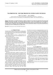
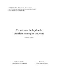
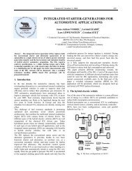
The OFDMA multi-user access technique is usually based on a frequency-time signal<br />
structure (see fig. 2.1.), which can be adjusted to various propagation conditions and is able to<br />
cope with the frequency selectivity generated by the multipath propagation and the time<br />
variability generated by the motion of the mobile station. Such a signal structure, called „bin” or<br />
„chunk”, is proposed for the <strong>LTE</strong> („Long Term Evolution”, also called 3.9G) mobile<br />
communication systems, [And05] [Bar06] [Chi06] [Hye06] [Kat06] [Pel05] [Sie06], which are<br />
still being standardized, as well as for the future 4G mobile communication systems [Win05_1].<br />
Within these chunks, coded or non-coded adaptive QAM modulations are employed [Bot04]<br />
[Ste03] [Win05_1], based on the channel measurements and channel-state prediction, made by<br />
the mobile station. These operations require the use of a number of spread pilot symbols within<br />
the chunk, [Ste03] [Win05_1]; some certain sub-carriers are also only used for synchronization<br />
and channel measurement operations. The allocation of chunks to different users on the<br />
downlink employs methods that usually take into consideration the predicted instantaneous<br />
signal to noise ratio in the frequency bands of the different chunks. The allocation function is<br />
performed by a scheduler block.<br />
time-frequency chuncks<br />
chunk bandwidth<br />
chunk duration<br />
chunk structure<br />
m OFDM symbols<br />
n OFDM subcarriers<br />
subcarrier separation<br />
period of OFDM symbol<br />
Fig. 2.1. Principle of OFDMA multi-user access<br />
and the chunk structure.<br />
The OFDMA multi-user access technique is employed in several wireless and high-speed<br />
mobile transmission systems. The IEEE 802.16.x (x=a,…,e) standards specify such OFDMA<br />
multi-user access techniques (called SOFDMA – „Scalable OFDMA”) [Yag04]. This technique<br />
is based on a structure of time-frequency signal, called burst, whose size is variable, as a function<br />
of the channel parameters. In this case, the scheduling operation is based on a special type of<br />
„frequency hopping” technique (called „distributed sub-carrier permutation”), which is capable<br />
of successfully managing the diversity in frequency and variability in time of the channel<br />
[Yag04]. The duplex transmission mode could be TDD or FDD adapted to the „half-duplex”<br />
operation mode. The above mentioned standards specify as modulation techniques, the coded<br />
QAM adaptive modulations, [Yag04].<br />
3
TUCN – Data Transmission Laboratory<br />
Another competitive technology for mobile high bit rate transmissions, called FLASH-<br />
OFDM, also based on the OFDMA multi-user access, is proposed by Flarion Technologies,<br />
[Lar01] and employs a type of „frequency hopping (FH)” allocation of user chunks.<br />
Besides the definition of the data structure (chunk) associated to the OFDMA access scheme,<br />
the following definitions must also be considered for the description of the transmission system:<br />
o Transmission Time Interval (TTI) [Bar06] [Chi06] – notion also used in 3G, represents<br />
the time interval within which the transmission parameters remain constant, i.e. the<br />
modulation and encoding techniques do not change. Considering the definition of the<br />
OFDMA chunk and the manner in which the adaptive coded modulations are employed<br />
within these chunks, the TTI can be considered equal to a chunk period.<br />
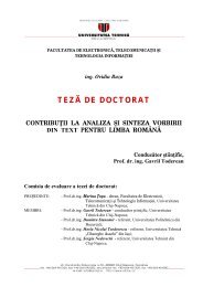
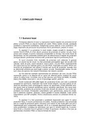
o The transport frame (or transport block) [Fau06] [See06] [Val06], represents the frame<br />
(block of data) with a duration of one TTI in which the user’s data is actually loaded.<br />
The transport frame can be a MAC radio frame or a fraction of it – see fig. 2.2.<br />
[Win05_1]; the MAC frame includes information regarding synchronization and access<br />
control; besides, it may also include data structures used in the management of uplink<br />
and downlink connections and data structures employed for signaling.<br />
A straightforward option is to equalize a transport frame to a chunk (solution proposed by<br />
WINNER), which will lead to severe limitations of the transport frames’ lengths (the set of<br />
coded modulations that can be used within a chunk is limited) and to a higher variability of the<br />
length of this frame as a function of the available radio resources at a certain moment. However,<br />
it will allow an easier employment of adaptive coded modulations – one codeword within a<br />
chunk with an imposed modulation.<br />
Another possibility is the construction of a transport frame composed of several chunks; this<br />
approach would allow longer frames and would reduce the frame length’s variability with<br />
available resources (a frame of a certain length could be loaded in several ways on the OFDMA<br />
chunks), but it will generate problems in the implementation of the coded modulations.<br />
A possible solution for these problems would be the separation of the coding and the<br />
adaptive modulation. The bits of a frame are first encoded with a certain error correction code<br />
and the obtained sequence is mapped on several chunks employing different modulations. The<br />
modulation used is independently adapted to the particular transmission conditions of each<br />
chunk. The adaptive change of codes is possible in this case as well, but it must be performed<br />
based on certain parameters that characterize the transmission performances in several chunks, in<br />
which different modulations are used.<br />
4<br />
preamble<br />
sync.+<br />
access control<br />
MAC frame<br />
slot slot<br />
DL UL<br />
DL UL<br />
MAC superframe<br />
duplex guard time<br />
DL UL<br />
one time slot = 1 chunk/transport frame period in FDD mode; 3 chunkstransport frame period in TDD mode<br />
one radio superframe = 8 or 16 radio frames<br />
Fig. 2.2. MAC frame and superframe structures associated to the OFDMA multiuser access technique.
<strong>LTE</strong> <strong>Emulator</strong> version 1.0 – technical report<br />
3. Operating principle and basic structure of the <strong>LTE</strong> emulator<br />
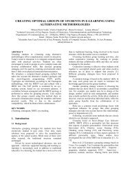
The operating principle of the emulator consists of the interception of packets containing the<br />
data destined to (generated by) the main user, the one being tested, and the delay and/or error<br />
insertion in these packets, similarly to the delay and error insertion produced by a transmission<br />
through a radio system with the specified parameters. The error and delay insertion is made<br />
according to delay and error statistics (probability density functions - pdf) obtained from the<br />
simulation of the radio transmission over the specified system or from processing certain<br />
measurements, if these are available. A schematic representation of the chain of processing that<br />
must be performed by the emulator is presented in fig. 3.1.<br />
Fig. 3.1. Chain of processing performed by the <strong>LTE</strong> emulator.<br />
An important problem of this approach is the large number of data structures (files, tables)<br />
containing statistics that have to be employed, each scenario and each system configuration<br />
requiring other statistics (distributions – pdf functions). This generates problems regarding not<br />
only the storage of this data, but also their accessibility. Decreasing the number of these statistics<br />
is, therefore, a fundamental requirement.<br />
The main idea regarding the statistics generation (error and delay distributions) is the<br />
separation of the parameters regarding the transmission scenarios and configurations into two<br />
groups, out of which only one is explicitly used during the simulation (statistics generation)<br />
process. Then, only during the emulation process, the two categories of parameters are<br />
considered in a combined manner.<br />
Practically, the main parameter used during the simulation process is the value of the signal<br />
to noise ratio of the first arrived path of the multipath model, SNR0, (details are presented in<br />
chapter 5. paragraph 5.1. describing the simulation process and the used radio channel model),<br />
separate statistics being generated for each value of SNR0; then, the required value for the SNR0<br />
is computed in the emulator and the data structures with their corresponding statistics are<br />
selected. Therefore, the simulation process involves the radio channel model (multipath<br />
propagation model and the fading model due to motion) and the load of the channel carrier in the<br />
cell, i.e. the number of active users and their characteristics (the service offered, average rate).<br />
The present version of the emulator and the corresponding simulator employ only a single<br />
channel carrier.<br />
5
TUCN – Data Transmission Laboratory<br />
The second group of parameters is also considered in the emulation process, i.e. the ones<br />
referring to the cell dimension (the cell is assumed circular, with a given radius), type of cell<br />
(urban/rural, small/large), the noise and/or interference distribution, mobile speed and its motion<br />
law and characteristics of the base station transceiver (carrier frequency, transmission power,<br />
height of the antenna). The value of the SNR0 is computed by using these parameters and tables<br />
with bit error and delay distributions are selected, according to the SNR0 value, out of a group of<br />
tables corresponding to the carrier frequency, multipath propagation profile and the cell carrier<br />
load.<br />
The speed of the user can be set both in the simulation and emulation processes. The two<br />
speeds do not have to be equal, if the synchronization/equalization operations are considered to<br />
be ideal, because the speed does not affect the probability density functions, if the simulation is<br />
performed within a sufficiently large time interval. Therefore, different values of the mobile’s<br />
speed do not require tables with different statistics. The velocity of the user is used in the<br />
simulation process, as well as in the emulation one, for computing the coherence time of the<br />
channel [Rap01] [Skl97], which has to be greater than the TTI interval. The channel<br />
characteristics are considered constant within the coherence time interval and, during this<br />
interval, only a single value is employed both for the instantaneous rate (number of bits/TTI) and<br />
the number of errors/TTI (the error distribution can vary within the data packet).<br />
3.1. Functional blocks of the emulator. Parameters of the functional blocks<br />
6<br />
3.1.1. The signal to noise ratio computation block<br />
This block has the purpose of reading the parameters of the cell (the geometry of the cell), of<br />
the base station transceiver and of the user’s mobility and to compute the value of the SNR0.<br />
Meanwhile the block provides the display of the main user’s trajectory within the cell. The<br />
parameters that are processed by this block, divided into 4 groups, are the following (see also fig.<br />
3.2.):<br />
o cell radius (circular cell) expressed in km;<br />
o cell dimension: small cell (radius ≤1km) and large cell (radius > 1km);<br />
o cell type: urban, suburban, rural;<br />
Note: the last two parameters select the formulae used for the computation of the<br />
attenuation, referred to the base station (center of the cell), i.e. the formulae that are<br />
used to compute the large scale fading, which depends on the cell-type.<br />
o channel carrier frequency, expressed in MHz;<br />
o transmission power of the base station, expressed in dBm;<br />
o noise power expressed in dBm;<br />
Note: in this emulator version, the noise spectral power density is considered<br />
constant in the entire cell.<br />
o height of the antenna of the base station transceiver, expressed in m.<br />
Note: height of the user’s antenna is considered constant and equal to 1.5m;<br />
o speed of the user, expressed in km/h;<br />
Note: the speed of the mobile must be chosen such that the coherence time of the<br />
mobile radio channel is greater or equal to the duration of the transport frame. The<br />
computation of the coherence time is made according to relation (2). In the present<br />
version, the emulator does not check the fulfillment of this condition; this task is to<br />
be accomplished by the user, when setting the emulation parameters.<br />
o the mobile’s motion law. It involves the function that describes the position of the<br />
mobile in time, within the cell, as a function of the cell’s dimension and the mobile
<strong>LTE</strong> <strong>Emulator</strong> version 1.0 – technical report<br />
speed (of the main user that is tested). The four motion laws that are implemented are<br />
defined bellow:<br />
random motion – a linear movement with random change of the motion direction at<br />
each second;<br />
linear motion – o linear continuous movement up to the edge of the cell where the<br />
motion direction is randomly changed;<br />
movement on a spiral [Spi] – the mobile moves on a spiral starting at the center of<br />
the cell and ending at the edge of the circular cell. The number of loops of the spiral<br />
is established randomly. When the mobile reaches the edge of the cell, it turns back<br />
to the center of the cell on the same spiral. In the moment when the mobile reaches<br />
the center of the cell a new spiral is generated with a random number of loops;<br />
circular movement on a circle with imposed radius;<br />
The mobile position is modified every second, this being also the time interval when the<br />
SNR0 signal to noise ratio is recomputed.<br />
The motion of the mobile can be suppressed, for different testing operations, and the value<br />
of the SNR0 (the signal to noise ratio associated to the first multipath propagation path) can be<br />
imposed by the user.<br />
Fig. 3.2. User interface of the signal to noise ratio computation block.<br />
The relations used to calculate the channel attenuation between the mobile and the base<br />
station transceiver are the following:<br />
o for cells with large dimensions (radius>1km) the COST-231 model is used; this model is<br />
an extension of the Hata model for large scale fading [Rap01]. Small empirical changes<br />
were added in the implementation of this model to correct the attenuation in points<br />
7
TUCN – Data Transmission Laboratory<br />
8<br />
located closely to the cell center, i.e. points located closely to the transmission antenna of<br />
the base station transceiver;<br />
o for cells with small dimensions (radius < 1km) the Wideband PCS Microcell Model<br />
[Rap01] is used. Small changes were also added in the implementation of this model to<br />
correct the attenuation in points located closely to the cell center;<br />
Calculation of the SNR0 value in a point x is performed according to relation (1).<br />
SNR<br />
P<br />
s ( x)<br />
= ⋅ a(<br />
x)<br />
0 (1)<br />
Pn<br />
where Ps is the transmitted signal power, Pn is the noise power, and a(x) is the attenuation<br />
calculated in point x.<br />
The „Emulate” button starts/stops the emulation process; when this button is in the Start<br />
position, an ideal channel with a bit rate limited only by the computation capacity of the<br />
computer which runs the program, is emulated.<br />
Another important parameter of the emulation process is the radio channel coherence time,<br />
parameters which makes the link between the speed of the mobile and the variability of the<br />
mobile radio channel at a given carrier frequency. This parameter is also calculated in this block<br />
and is then transferred to the delay and error generation block. The calculation of the coherence<br />
time is performed according to relation (2), [Rap01].<br />
t<br />
c<br />
9 0.<br />
423<br />
= = ;<br />
2<br />
16 ⋅π<br />
⋅ f f<br />
m<br />
m<br />
f<br />
m<br />
v ⋅ f<br />
=<br />
c<br />
In (2) v is the speed of the mobile, fc is the radio channel central frequency, meaning the used<br />
carrier frequency, c is the speed of the light in vacuum, fm is the maximum Doppler frequency,<br />
[Rap01].<br />
3.1.2. The command and control block<br />
This block selects the network cards of the computer which runs the emulator, network cards<br />
which receive respectively transmit the data packets, and it also takes the MAC addresses of<br />
network card which delivers the input data packets and of the one towards which the processed<br />
packets are transmitted. It also sets the capture-buffer length, adjusts the nominal transfer rate<br />
through the emulator, selects the files with delay and bit-error statistics of the emulated<br />
transmission, displays the number of transferred bytes through the emulator in an imposed time<br />
interval, displays the average transferred bit rate and establishes the time interval used to<br />
compute the average bit rate.<br />
The present version only emulates the downlink connection (base station – mobile user). The<br />
local network card(s) which ensures the connection with the computer (or computers) acting as<br />
mobile node(s) is selected from the list „Client NIC” (see fig. 3.3.) and the MAC address<br />
(addresses) of the network card(s) of the computer(s) acting as mobile node(s) is (are)<br />
established with the edit window called „Edit MAC Address List”; the window appears if a<br />
double click is applied on the list box called „Mobile Node MAC”, and the mentioned addresses<br />
can be visualized with this list box. The selection of the local network card which ensures the<br />
connection with the computer (or computers) acting as base station is made from the list „Server<br />
NIC” (see fig. 3.3.), and setting the MAC address (addresses) of the network card(s) of the<br />
computer(s) acting as base station, is (are) accomplished by the same edit window (the „Edit<br />
MAC Address List” window). The window appears if a double click is applied on the list box<br />
called „Base Station MAC”, and the mentioned addresses can be visualized with this list box –<br />
see fig. 3.3. In the downlink direction, each packet having the source address included in the<br />
Base Station MAC list is captured; these packets are processed and delivered to the local<br />
network card(s) which connects the mobile node computer(s). Similarly, in the uplink direction,<br />
c<br />
(2)
<strong>LTE</strong> <strong>Emulator</strong> version 1.0 – technical report<br />
each packet having the source address included in the Mobile Node MAC list is captured; these<br />
packets are delivered to the local network card(s) which connects the base station computer(s).<br />
To insert a MAC address in the list this address have to be typed in the edit space of the<br />
„Edit MAC Address List” window and then the „Add” button must be pushed – see fig. 3.3. The<br />
window could be closed, leading to a return in the main interface, by pushing the „Return”<br />
button or by clicking on the X sign from the right upper corner. To remove an address from the<br />
list, select that address with the „mouse” and then push the „Remove” button – see fig. 3.3.<br />
The compensation of the possible supplementary delays inserted by the computer which<br />
runs the emulator requires the adjustment of the transfer rate. This operation uses a data<br />
generator with adjustable constant bit rate, which has to be used in an emulation process of<br />
channel with high signal to noise ratio, channel witch has no errors and for which the exact<br />
average bit rate is known (see paragraph 3.1.1. related to the possibility to select a certain signal<br />
to noise ratio for emulation).<br />
The adjustment of the bit rate is accomplished with the „Scroll Bar” called „Bit rate<br />
adjustment” and the adjustment value is displayed in the „Adj_value” edit box. The adjustment<br />
value has no direct significance; it just indicates how great is the deviation that has to be<br />
corrected, relatively to the ideal situation when the computer does not insert supplementary<br />
delays. See also chapter 8. that deals with the adjustment of the bit rate transferred through the<br />
emulator.<br />
The edit box „Emulation Statistics” allows the selection of the file in which the tables with<br />
statistics corresponding to the configuration of the emulated system are stored. The name and the<br />
path of the file containing the statistics have to be introduced in this edit box. If the path and/or<br />
name are incorrect, an error message is displayed and the emulation process is stopped. The path<br />
and name of the file can be reintroduced after pushing the “Start/Stop” button.<br />
The „Average Bit Rate” edit-box displays the average bit rate, in kbps, computed over a<br />
time interval (expressed in seconds) specified in the „Averaging interval” edit box. The „Transm.<br />
bytes” edit box displays the number of transferred bytes, in Kbytes, starting from the beginning<br />
of the emulation or from the moment when the “Clear tr. bytes” button is pushed, when the<br />
counter associated to number of transmitted bytes is cleared – see fig. 3.3.<br />
Fig. 3.3 User interface of the command and control block.<br />
9
TUCN – Data Transmission Laboratory<br />
The parameters associated to the command and control block are read and the emulation<br />
process is started by pushing the “Start/Stop” button.<br />
When this button is pushed the following actions are performed:<br />
o the emulation parameters are read from the interface;<br />
o the file containing the statistics required by the emulation is read and the data structures<br />
storing these statistics during the emulation process are built; these structures are built in<br />
such a way to allow a fast generation of the random variables associated to the<br />
instantaneous bit rate and to the error distribution – see paragraph 5.2.2. related to the<br />
generation of the statistics tables and paragraph 3.2.2. related to the generation of<br />
random variables distributed according a given pdf function);<br />
o the communication channels to the network cards associated to the emulator, which<br />
receive/transmit data packets, are open;<br />
o the packet-capture block is initialized;<br />
o the threads that emulate the transmissions in the downlink and uplink directions are<br />
launched.<br />
10<br />
3.1.3. The emulation statistics display block<br />
In parallel with emulation of the transmission (delay of the received packets and error<br />
insertion in these packets), some significant statistics related to the emulation process are<br />
displayed.<br />
Three graphs included in the user interface are displayed, namely the evolution in time of<br />
the average bit rate, the time-evolution of the number of inserted errors and of the average delay<br />
of the packets passing through the emulator. These graphs allow the correlation between the<br />
position of the main user (the emulated user) inside the cell, which determines its instantaneous<br />
SNR, and the main parameters that define the transmission quality.<br />
3.2. Main operations performed in the emulation process<br />
The operations performed by the emulator are grouped in 3 separate threads [Thr] namely:<br />
o the main thread (the main program) – performs the operations related to the SNR<br />
calculation, as explained in paragraph 3.1.1. dedicated to the signal to noise ratio<br />
computation block. This operation uses the system timer, with a timing of 1s, to generate<br />
the real time. The actualization of the mobile position and implicitly of the SNR value<br />
is performed at each second;<br />
o the thread associated to the uplink connection – performs in the present version only the<br />
filtering and interception of the packets received from the computer (or computers)<br />
acting as mobile station(s). The captured packets are transferred at the network card<br />
which ensures the connection with the computer (or computers) acting as base station(s)<br />
without any delays and errors. The speed in the uplink is limited only by the processing<br />
time of the packet filtering and capturing operations;<br />
o the thread associated to the downlink connection – performs the filtering and<br />
interception of the packets received from the computer (or computers) acting as base<br />
station(s), the delay of the received packets and the error insertion according to the<br />
appropriate statistics which characterize the emulated situation;<br />
If the emulation process is stopped, the packets are only intercepted and transmitted to the<br />
network card ensuring the connection with the computer (or computers) acting as mobile<br />
station(s).<br />
If the emulation process is enabled, the intercepted packets are read from the reception<br />
buffer according to the instantaneous bit rate, i.e. the numbers of bytes calculated according to<br />
the pdf of the instantaneous bit rate are read in each TTI interval and then errors are inserted in<br />
these bytes according to the distribution of the errors.
<strong>LTE</strong> <strong>Emulator</strong> version 1.0 – technical report<br />
These thread computes the average bit rate on a specified time interval (see paragraph 3.1.2.<br />
dedicated to command and control block) and uses a timer with a 1s timing; the procedure<br />
associated to this timer displays this average bit rate and the evolution in time of this average<br />
value. The same procedure also computes the average delay per packet/second and displays the<br />
evolution in time of this value.<br />
The timing required by the generation of the instantaneous bit rate, meaning the generation<br />
of the TTI intervals, uses the high precision timer of the system, timer which can be accessed<br />
by the following functions [Que]:<br />
o „QueryPerformanceFrequency(*LARGE_INTEGER)” – gives the frequency of the high<br />
precision timer;<br />
o „QueryPerformanceCounter(*LARGE_INTEGER)” – reads the counter associated to<br />
this timer;<br />
3.2.1. Interception and filtering of the processed packets<br />
The solution used for implementation of the present emulator is based on interception of<br />
MAC Ethernet packets, approach that ensures independence of the higher-layer protocols. The<br />
packet-interception is accomplished by using the functions of the WinPcap [Wpc] library for the<br />
Windows operating system. The intercepted packets are stored in buffers managed by the<br />
WinPcap functions, their lengths being controlled from the user interface of the command and<br />
control block. This library also includes special functions for packet-filtering at the kernel level,<br />
facility used in the present implementation the decrease the processing time.<br />
The functions of the WinPcap library that are used in the present implementation are the<br />
following (for supplementary details see [Wpc]):<br />
int pcap_findalldevs (pcap_if_t **alldevsp, char *errbuf);<br />
- generates a list of network devices which can be open with the “pcap_open_live()”<br />
function; for each device it associates a “pcap_if_t” descriptor, which is a structure that contains<br />
information related to the network device that can access it; errbuf, is a string which contains a<br />
possible error message; the function returns 0 for successful operation and -1 otherwise;<br />
pcap_t pcap_open_live (const char *device, int snaplen, int promisc, int to_ms, char *ebuf);<br />
- generates a „packet capture descriptor” pcap_t ; this is a structure which contains data<br />
necessary to access a network device and to perform a packet capture; device – is the name of the<br />
accessed network device; snaplen – specifies the maximum number of captured bytes; promisc –<br />
specifies the functioning mode of the network device during the capture; to_ms – specifies the<br />
„read timeout” in ms;<br />
int pcap_sendpacket (pcap_t *p, u_char *buf, int size);<br />
- allows to send a “raw” packet (a full packet containing all the protocol headers, loaded<br />
in the packet by the sending application); the pointer p of type pcap_t describes the network<br />
interface and the capture process; buf – is the buffer which stores the bytes to be loaded in the<br />
packet (the entire structure of the packet excepting the CRC, which is computed by the network<br />
interface); size – length of the packet which will be transmitted;<br />
int pcap_next_ex (pcap_t *p, struct pcap_pkthdr **pkt_header, const u_char **pkt_data)<br />
- the function is used to capture the next available packet; pkt_header – is a pointer to a<br />
pcap_pkthd type structure, which contains the header of the captured packet, pkt_data – is a<br />
pointer to a string containing the data bytes of the captured packet;<br />
void pcap_close (pcap_t *p);<br />
- frees the memory and resources related to the packet capture process;<br />
int pcap_compile (pcap_t *p, struct bpf_program *fp, char *str, int optimize, bpf_u_int32<br />
netmask)<br />
11
TUCN – Data Transmission Laboratory<br />
- ensures the compilation of a packet filter, converting a high level filtering expression<br />
into a program which can be interpreted by the kernel-level filtering procedures; for more details,<br />
see “Filtering expression syntax” [Wpc];<br />
int pcap_setfilter (pcap_t *p, struct bpf_program *fp)<br />
12<br />
- associates a filter to a capture process – details can be found in [Wpc];<br />
3.2.2. Delay of the intercepted packets and error insertion in these packets<br />
The emulation of the packet-delay is accomplished by the generation of the instantaneous<br />
bit rate; the intercepted data are transferred from the buffer of the input network-card to the<br />
buffer of the output network-card in the rhythm of this instantaneous bit rate. In this way, the<br />
packets delays are generated automatically. This is practically accomplished by generating the<br />
number of bits/TTI at the beginning of each channel coherence time interval; additional details<br />
can be found in paragraph 5.2.2. that deals with the generation of the tables with statistics in the<br />
simulation process. The error-patterns inserted in the intercepted (and filtered) packets are<br />
described by two statistics; one of them contains the number of errors/TTI and the other one, the<br />
effective error-distribution (localization) inside that error packet.<br />
The values taken by the number of bits/TTI and by the number of errors/TTI are jointly<br />
processed by means of a discreet bi-dimensional random variable described by a finite set of “no.<br />
errors/TTI – no. bits/TTI” pairs, which is obtained after processing the initial data provided by<br />
the simulation. A cumulative probability function (cdf), is associated to the above mentioned<br />
pairs, see fig. 3.4.; for details see paragraph 5.2.2.<br />
This distribution is represented (stored) using 3 tables, two of them containing the values of<br />
no. errors/TTI and respectively no. bits/TTI, i.e. the previously mentioned pairs; the third table<br />
contains the values of the cumulative distribution function (cdf) associate to these pairs.<br />
bit1 bit2 bit3 bit4 bit5 ...... bitn-1 bitn<br />
err1 err2 err3 err4 err5 ...... errn-1 errn<br />
P1 P2 P3 P4 P5 ...... Pn-1 Pn<br />
bits/TTI<br />
bit errors /TTI<br />
cdf function values<br />
Fig. 3.4. Representation of the bi-dimensional random variable no. errors/TTI – no. bits/TTI.<br />
To generate a pair of random variable according to an imposed probability function the<br />
following steps have to be performed:<br />
o a uniformly distributed variable within the interval [0 , 1] is generated; this could be<br />
accomplished by using a random number generator, e.g. the generator offered by the<br />
programming environment. Then, the generated values are divided by the maxim value<br />
that was be generated;<br />
o the Pa and Pa+1 values of the cdf function which frame the currently generated value of<br />
the uniform random variable are established; the minimum and maximum possible<br />
values of the cdf function, i.e. 0 and 1, may not be stored in the tables;<br />
o the values erra and bita, meaning no. errors/TTI and no. bits/TTI corresponding to value<br />
Pa of the cdf function which lower-bounds the currently generated value of the uniform<br />
random variable, are extracted from the appropriate tables; more details can be found in<br />
[Bot02] [Bot00]. The number of bits/TTI is transformed in number of bytes/TTI for an<br />
easier generation of the instantaneous transfer rate;<br />
The error-patterns generation has to consider not only the number or errors/TTI, but also the<br />
distribution pattern of these errors (the error-localization). For this distribution pattern, a second<br />
statistics which describes the distance between consecutive bit errors is used, more details being<br />
available in paragraph 5.2.2. This statistics is represented by two tables, one containing the
<strong>LTE</strong> <strong>Emulator</strong> version 1.0 – technical report<br />
quantized values of the distance between consecutive errors and the other one containing the<br />
values of the associated cumulative density function – see fig. 3.5.<br />
err_dist1 err_dist2 err_dist3 err_dist4 err_dist5 ...... err_distn-1 err_distn<br />
distance between<br />
consecutive errors<br />
P1 P2 P3 P4 P5 ...... Pn-1 Pn cdf function values<br />
Fig. 3.5. Representation of the random variable which gives the distance between consecutive errors.<br />
The values of this random variable are generated according to the previously presented<br />
algorithm. A number of distances, equaling the number of errors/TTI, are generated at first, then<br />
the algorithm computes the error-positions and finally, the values of the bits located in these<br />
positions are changed. The search of the error positions starts at the beginning of the group of<br />
bits corresponding to the current TTI interval and a modulo (no. bits/TTI) arithmetic is used; if<br />
an error-position index is greater than the length of the group of bits corresponding to the current<br />
TTI interval, then the search for this position continues circularly from the beginning of the<br />
group. Such a situation could occur due to the fact that the number of errors and the positions of<br />
these errors, i.e. the distribution pattern of these errors, are characterized by different noncorrelated<br />
distributions.<br />
13
TUCN – Data Transmission Laboratory<br />
4. The parameters of the <strong>LTE</strong> simulator<br />
Two categories of users (mobile stations) are considered in the simulations that provide the<br />
statistics which are employed by the emulator:<br />
o one main user, for which the simulation is actually performed;<br />
o a group of secondary users, which makes up the loading of the cell carrier;<br />
The delay (bit rate) and error-probability statistics are built up only for the main user, by<br />
performing in the simulator all the operations (processing) included in the transmission chain.<br />
For the secondary users, the simulator performs only the processing required by the<br />
generation of the characteristic of the radio channel and those involved in the allocation of the<br />
radio resources, which affects the allocation of the radio resources for the main user who is<br />
actually emulated; this approach allows the simulation of the effect of the cell-carrier loading.<br />
The description of the processing performed for the two types of users requires a previous<br />
definition of the data structures employed in the transmission process, the specification of the<br />
modulation and coding techniques employed, the definition of parameters that characterize the<br />
cell and the specification of the parameters that individually define each user.<br />
4.1. Parameters that characterize the cell in the simulation process<br />
The parameters that characterize the cell are defined in a distributed manner between the<br />
simulator and the emulator, as shown in chapter 3. which describes the operating principle of the<br />
emulator.<br />
This way of defining the parameters is employed to reduce as much as possible the number<br />
of simulations, and implicitly the number of statistics-files, required to perform the emulation;<br />
this approach ensures also a reasonable amount of processing performed by the emulator. To<br />
accomplish this goal, the simulator makes use only of the parameters that are independent of the<br />
cell-geometry and of the base-station characteristics; this approach allows for the employment of<br />
the statistics delivered by a simulation in more emulations.<br />
In the simulation process, the cell is practically characterized by:<br />
o the number of active users;<br />
o the multipath propagation profile of the channel;<br />
o the radio-channel carrier frequency (cell-carrier);<br />
o the parameters of OFDM modulation;<br />
o the probability density function of the fast-fading inserted by the users’ motion;<br />
The limits of SNR domain of the signal received by the main user and the limit-values of the<br />
attenuation of the signal received by the secondary users also describe, in an indirect manner, the<br />
cell employed in the simulation process. All the above parameters can be set in the user-interface,<br />
except for the probability density function of the fast fading, which is implemented as a Rayleigh<br />
fading.<br />
The multipath propagation profile is specified by the number of the secondary propagation<br />
paths and by the delays and attenuations inserted by these paths, referred to the first arrived path<br />
(the main path).<br />
The main path is considered to be the first arrived one, with a minimum delay, and, since it<br />
is a reference path, its relative delay and attenuation are not explicitly specified, being equaled to<br />
zero. The absolute delay of the reference path is of little importance for the performances of the<br />
physical level; it could only affect the timing aspects of the higher-level protocols. As for the<br />
absolute attenuation of the first path, it is inserted by the large-scale fading, and is computed and<br />
considered in the emulation process. If required, the absolute delay inserted by the main path<br />
might be inserted in a subsequent version of the emulator.<br />
The multipath propagation profile is combined with the fast fading generated by the user’s<br />
motion, each individual propagation path being affected separately by a Rayleigh-distributed<br />
14
<strong>LTE</strong> <strong>Emulator</strong> version 1.0 – technical report<br />
fading. Additional information regarding the generation of the mobile multipath radio channel<br />
are presented in paragraph 5.1.<br />
Fig. 4.1. Specification of OFDM and multipath propagation profile in the<br />
user interface of the simulator.<br />
The OFDM modulation is specified by the following parameters: the carrier (cell carrier)frequency,<br />
the frequency-separation between sub-carriers, the number of sub-carriers used for<br />
transmission and the guard-interval of the OFDM symbols. Figure 4.1. shows the user interface<br />
of the simulator used to set the specifications for the parameters of the OFDM modulation and of<br />
the multipath propagation profile. The particular multipath profile presented is the one of WP5<br />
channel model [Win05_1], with 18 propagation paths, for a carrier frequency of 5GHz.<br />
4.2. Parameters that characterize the users in the simulation process<br />
Each user mobile station is defined by a set of four parameters, namely:<br />
o the user’s moving speed, employed in the generation of the small-scale fading. Actually<br />
it is employed for the computation of the coherence time Tc, (2); additional details can be<br />
found in paragraph 5.1. The coherence time is also used for the simulation of the<br />
displacement of the secondary users by changing the attenuation of the signal received<br />
by such a user in the rhythm given by its corresponding coherence time. Since the<br />
coherence time is lower-bounded by the parameters of the OFDMA scheme (TTI), the<br />
maximum user speed should be limited accordingly, so that the coherence time should<br />
not be too small.<br />
Note: the current version of the emulator does not check if the condition Tc >TTI is<br />
fulfilled.<br />
o the absolute attenuation of the main propagation path, which is specified for the<br />
secondary users to allow the simulation of their position, relative to the position of the<br />
main user. The attenuation of the first path of the main user is considered 0 dB, the<br />
absolute attenuation of his main path being computed within the emulation process, see<br />
chapter 3. , paragraph 3.1.1. dedicated to the computation of SNR0 within the emulator.<br />
Note that the relative attenuations of the secondary users might have negative values,<br />
15
TUCN – Data Transmission Laboratory<br />
indicating that their position is closer to the center of the cell (base-station) than the one<br />
of the main user; additional details are to be found in chapter 5. , which describes the<br />
operating principle of the simulator.<br />
o the class and priority of the service offered to the user – an unlimited number of<br />
services may be defined, the services with smaller indexes having higher priorities. The<br />
Winner project [Win05_2] defined 21 classes of services and 24 generic applications.<br />
Those definitions are a basis for the definition of a set of possible services. The priority<br />
and bit rate assigned to each service are employed in the process that allocates the radio<br />
resources to each user, as shown in paragraph 5.2.1. that describes the scheduler block;<br />
o the average bit rate associated to the service provided to the user.<br />
Figure 4.2. displays the simulator interface employed for the setting of the user parameters;<br />
the example shown considers 5 users on the cell carrier.<br />
4.3. Parameters that define the modulation and FEC coding techniques and<br />
the OFDM access method in the simulator<br />
Because the modulation and FEC encoding methods employed on the OFDM sub-carriers<br />
and the data structures employed in transmission are strongly correlated, their parameters are<br />
defined in the same window.<br />
16<br />
Fig. 4.2. Setting the users’ parameters in the simulator interface.<br />
4.3.1. Parameters of the adaptive modulations employed on OFDM sub-carriers<br />
Each OFDM sub-carrier is modulated with a square QAM or a 2-PSK constellation defined<br />
by the number of bits/symbol. The accepted numbers of bits/symbol are 1, 2, 4, and 6 and<br />
optionally 8, i.e. the signal constellations employed are respectively 2PSK, QPSK, 16QAM,<br />
64QAM and optionally 256QAM.<br />
The above mentioned modulations are employed on groups of sub-carriers (OFDM chunks –<br />
see chapter 2.). The adaptive employment of these modulations require the setting of some SNR<br />
domains, within which each modulation should be employed according to a given criterion (biterror<br />
rate or symbol-error rate), these SNR domains being separated by SNR thresholds. The<br />
simulator interface allows the setting of the SNR thresholds, but the numbers of bits/symbol can<br />
not be modified, since only the modulations mentioned above can be employed. Actually, the<br />
interface allows the modification of their values, e.g. to odd values, but the modification has no<br />
effect, since the numbers of bits/symbol are imposed to be either even or 1. The interface<br />
window that allows the setting of the SNR domains for each modulation is presented in the lefthand<br />
side of figure 4.3. The 256-QAM constellation can be validated in the corresponding<br />
check-box.<br />
4.3.2. Parameters of the error-correcting codes employed<br />
The simulator employs LDPC FEC codes, see [Gal03] [Mck99], and more specific it<br />
employs regular L(2,q)-LDPC codes, as defined in [Ele02] and [ITU]. These codes are<br />
characterized by three parameters K, J and P, P being a prime number, K, J ≥ 3 and J < K ≤ P.<br />
The codeword length equals K·P and the number of check bits is given by the product J·P.
<strong>LTE</strong> <strong>Emulator</strong> version 1.0 – technical report<br />
The length of an LDPC codeword can be modified by shortening the code, i.e. the removal<br />
of a number of information bits, which leads to a decrease of the code’s coding rate. The codes<br />
employed are shortened, so that the lengths of the codewords would match the lengths of the<br />
transport frames, Lframe. The coding rate of the shortened codes, Rc, is expressed by:<br />
R<br />
c<br />
L frame − J ⋅ P<br />
= (3)<br />
L<br />
frame<br />
Fig. 4.3. Setting the parameters of the adaptive modulations, of the error-correcting codes and of the<br />
data structure in the simulator interface.<br />
Five codes are defined by default for each length of the transport frame, but more codes can<br />
be defined in simulator.<br />
The codes employed for various lengths of the transport frame are selected so that they<br />
should ensure about the same coding rate.<br />
The parameters „Initial_rate_index” and „No_retransm” see figure 4.3., are related to the<br />
H-ARQ procedure, [Fau06] [See06] [Val06].<br />
The first parameter indicates the code that is employed in the first transmission of a transport<br />
frame, while the second shows the maximum number of retransmission attempts of a transport<br />
frame, if bit-errors occur. For each retransmission the FEC code is changed, by using the next<br />
code on the list, code that has smaller coding rate. The maximum number of retransmission<br />
should be smaller with 1 than the number of codes defined for each transport frame length. The<br />
number of transport frame lengths (”No_transp_frames”), the number of FEC codes employed<br />
for each length of a transport frame (“No_codes/frame”), and the parameters of the FEC<br />
employed can be set in the simulator interface, see fig. 4.3., by filling in the appropriate boxes.<br />
Several default groups of codes, defined for several transport frame lengths are also presented in<br />
fig. 4.3.<br />
Note: the selection of the set of LDPC codes employed for each Lframe (and for each<br />
modulation) requires a careful evaluation of the throughputs provided by the<br />
resulting configurations (code +modulation).<br />
17
TUCN – Data Transmission Laboratory<br />
18<br />
4.3.3. Parameters of the data structures employed in transmission<br />
Two data structures are employed in the transmission process:<br />
o the chunk (or bin) – a group of adjacent sub-carriers during a number of OFDM-symbol<br />
periods;<br />
o the transport frame – composed of more chunks, spread in the frequency domain, in the<br />
same chunk interval<br />
Inside each chunk, the same modulation (and possible codes) is employed on all sub-carriers<br />
and during all OFDM-symbol periods of that chunk. The chunks that compose a transport frame<br />
may employ different configurations (modulation). Additional information regarding these issues<br />
can be found in chapter 2. dealing with OFDMA multi-user access.<br />
The parameters „Sbcarrs/chunk”, „OFDM Symb./chunk” set the chunk dimensions and<br />
parameter „Service symb./chunk” sets the number of sub-carriers (or scattered QAM symbols)<br />
within a chunk, which are employed for service purposes (synchronization, equalization,<br />
channel-measurement and are not payload symbols.<br />
The transport frames are defined only by their length (in bits), the exact structure (in chunks)<br />
being set dynamically by the resource allocation procedure (algorithm).<br />
Figure 4.3. presents an example of setting the data structures employed in transmission by<br />
the simulator.<br />
4.4 The main parameters of the simulation<br />
The main parameters that define a simulation process are the following:<br />
o the number of transport frames transmitted by each user (the main user and the<br />
secondary ones) during the simulation interval. The delay (or more specific the<br />
instantaneous bit-rate) and bit-error statistics of the main user are obtained using the bits<br />
transmitted by this user within the specified number of transport frames. Note that the<br />
numbers of bits transmitted by various users are not equal; they are depending of<br />
characteristics of the radio channel „seen” by each of them and of parameters of the<br />
service that is provided to each of them;<br />
o the maximum number of iterations performed by the MP („Message Passing”) decoding<br />
algorithm of the LDPC code, [Gal63], [Mck99]. The coding-decoding processes are<br />
performed only for the main user; therefore this parameter is significant only for this<br />
user;<br />
o the range of the SNR values of the first arrived propagation path, SNR0, across which the<br />
simulation is performed, parameter that is specified only for the main user. This range is<br />
specified by a minimum and maximum SNR0 values and by a sweeping step. A distinct<br />
simulation transmitting the specified number of transport frames is performed for each<br />
SNR0 value inside this domain; distinct statistics tables are generated for each simulation,<br />
see beginning of chapter 5. and paragraph 5.2.2. for additional information regarding the<br />
simulation’s principles and the way the statistics tables are generated;<br />
o the range of the channel attenuation (more specific of the first arrived path) for the<br />
secondary users. The range is defined by the minimum and maximum values of<br />
attenuation and by a sweeping step. The sign of the sweeping step changes<br />
independently for each user, when the current value of the attenuation reaches one of the<br />
limit values imposed. The attenuation is modified with a different rhythm for each user,<br />
rhythm that is correlated to the user’s speed and to the user’s coherence time. During<br />
each coherence interval this attenuation is modified with a sweeping step (one unit); see<br />
additional details in chapter 5. that deals with principles of the simulation process.<br />
Figure 4.4 shows the window that allows the setting of these parameters and their default<br />
values, as well as the main functional buttons of the simulation program.
<strong>LTE</strong> <strong>Emulator</strong> version 1.0 – technical report<br />
The „Read Settings” button reads the set values of all above mentioned parameters and<br />
initializes the tables/matrices required by various processing.<br />
The „Start” button calls the program sequences that actually perform the simulation; see the<br />
beginning of chapter 5. for the structure of the simulation program and paragraph 5.2. for<br />
information regarding the processing performed throughout the simulation. To obtain reliable<br />
error statistics, each simulation should be performed on a great number of transport frames; the<br />
minimum number of frames should be at least 10000.<br />
Fig. 4.4. Setting the main simulation<br />
parameters and display of intermediary<br />
simulation results in the user interface<br />
4.5. The output data delivered by the simulator<br />
The simulator delivers the files that contain the statistics of the delay and bit error-rate. The<br />
simulation results are delivered in two files:<br />
o the first one named „stat_file.txt” is a text file employed for the analysis of the generated<br />
statistics;<br />
o the second one, named „stat_file.sta”, is a binary file (file stream) which contains the<br />
cumulative distribution functions (cdf) associated to the two mentioned random variables.<br />
These functions are employed by the emulator to insert the delays and errors in the<br />
emulation process, see paragraph 3.2.2. describing the delay and error insertion in the<br />
intercepted packets.<br />
The ways the data are structured in these files are presented in paragraph 3.2.2., as well as in<br />
paragraph 5.2.2., which explains the generation of the statistics tables. Each simulation generates<br />
files with imposed name and extension; previously generated files are overwritten.<br />
Note: the user should rename the files generated by previous simulations, to avoid<br />
the loss of the information they contain.<br />
The simulator also displays some intermediary data during the simulation process, which are<br />
employed for the control of this process. It displays dynamically for the main user the number of<br />
transmitted bits, the number of bit-errors (with and without the employment of the errorcorrecting<br />
codes), the number of retransmissions and the number or incorrectly decoded<br />
transport frames, as shown in figure 4.4.<br />
19
TUCN – Data Transmission Laboratory<br />
5. The principle of the simulation process<br />
The design of the simulator has as a main goal the generation of instantaneous bit rate<br />
(delay) and bit error probability statistics which can be reused in several emulation processes,<br />
decreasing in this way the simulation-time and the amount of memory required to store the<br />
mentioned statistics. An important aspect is the removal of the parameters related to the cell<br />
geometry and to the base station transceiver from the simulation process; this approach allows<br />
the use of the same statistics to emulate the transmissions in cells with different characteristics.<br />
To achieve this goal, the simulation process uses as the main parameter the signal to noise ratio,<br />
of the path with the lowest delay of a multipath propagation scenario, SNR0. The simulations are<br />
performed across a range of signal to noise ratios, with an acceptably small separation step, each<br />
simulation generating a set of statistic tables. During the emulation process the SNR0 is<br />
calculated and the appropriate statistics tables are chosen – see first part chapter 3. and paragraph<br />
3.1.1., related to the operating principle of the emulator and to the calculation of the SNR0 value.<br />
The multipath propagation model and the cell load, meaning the number of users and the offered<br />
services, are imposed in the simulation process. Practically, the simulations must be performed<br />
for a limited, but representative, set of multipath propagation models and cell loads; a limited set<br />
means a number of several tens or hundreds scenarios. The dimensions of the statistic tables are<br />
relatively small, tens of kB, allowing the storage of a large number of such statistics on usual<br />
memory circuits.<br />
The simulation process considers two types of users, namely the main user, for which the<br />
tables with instantaneous bit rate and error probability statistics are generated, and a set of<br />
secondary users, which give the load of the cell carrier and which occupy radio resources.<br />
The simulation for a number of transport frames great enough to provide highly reliable<br />
statistics are performed for each value of SNR0 of the main user. The number of the transport<br />
frames has to be at least of several thousands; a larger number of transport frames ensure more<br />
reliable statistics, but also increases substantially the simulation time.<br />
This approach is equivalent to the movement of the main user on a circle with the center<br />
located in the base station and the radius imposed by the value of SNR0 and the used propagation<br />
model, model which depends on the cell type. The total signal to noise ratio used in the<br />
simulation process is computed based on the SNR0 value, on the multipath propagation profile,<br />
on the distribution of the fast fading due to the mobile motion, taking also into account the<br />
channel coherence time.<br />
The motions of the secondary users are simulated by the modification of an attenuation<br />
parameter associated to each secondary user; this parameter indicates the distance to the base<br />
station transceiver. It changes for each secondary user in the cadence of the channel coherence<br />
time specific to that user, i.e. a function of the user’s speed. This approach simulates a real case,<br />
where the main user moves on a circular trajectory around the base station and the other users<br />
move randomly inside the cell. In the emulation process the main user motion trajectory is<br />
changed, by moving him from one circle to another. The basic idea of the simulation process is<br />
presented in fig. 5.1.<br />
The attenuation parameter of the secondary users have to be located in a large domain (-30,<br />
+ 30dB), to allow a realistic simulation of the motion between the center and the edge of the cell.<br />
This domain must include both positive and negative values, to allow the simulation of the<br />
relative positions of the secondary users relative to the main user (a positive attenuation means<br />
that the secondary user is located farther to the center of the cell than the main user, while a<br />
negative attenuation means that the secondary user is located closer to the center of the cell than<br />
the main user). The calculation method of the total signal to noise ratio is presented in paragraph<br />
5.1. This signal to noise ratio includes the effect of the multipath propagation and of the motion<br />
generated fast fading and is used for radio resource allocation, both for the main user and the<br />
secondary users.<br />
20
BTS<br />
5.1. The channel model employed in the simulation process<br />
<strong>LTE</strong> <strong>Emulator</strong> version 1.0 – technical report<br />
The simulation process considers both the effects of the large scale fading, of the multipath<br />
propagation and of the small scale fading. The large scale fading is simulated by the signal to<br />
noise ratio associated to the first propagation path (with the lowest delay); the multipath<br />
propagation and the small scale fast fading are considered together, each separate propagation<br />
path being affected by a Rayleigh type fading. The channel model used is presented in fig. 5.2.,<br />
and it is identical with the model proposed in [Rap01].<br />
sin(t)<br />
secondary user<br />
main user<br />
x dB SNR<br />
Fig. 5.1. Illustration of the simulation process basic idea.<br />
ag<br />
mean attenuation<br />
(free space propagation<br />
log-normal fading)<br />
Fig. 5.2 Mobile radio channel<br />
model, affected by multipath<br />
propagation and motion generated<br />
fast fading.<br />
r(t)<br />
σ1<br />
τr1 τr2 τr3<br />
ar1 ar2 ar3<br />
r(t)<br />
σ2<br />
∑<br />
The Rayleigh type probability density function is given in (4). The relation gives the<br />
probability density of the Rayleigh faded signal envelope, r, and σ 2 represents the power of the<br />
signal affected by Rayleigh fading.<br />
r(t)<br />
σ3<br />
sout(t)<br />
r(t)<br />
σ4<br />
BTS<br />
relative delay<br />
(relative to<br />
reference path)<br />
secondary user<br />
main user<br />
y dB SNR<br />
relative attenuations<br />
(relative to<br />
reference path)<br />
Rayleigh fading<br />
(σi – rms. of the i-th path)<br />
multipath<br />
propagation<br />
21
TUCN – Data Transmission Laboratory<br />
22<br />
2<br />
p = ; 0 r ;<br />
2<br />
σ<br />
(4)<br />
( r)<br />
2<br />
⎧ r ⎛ r ⎞<br />
⎪ ⋅ exp 2<br />
2<br />
σ ⎜<br />
⎜−<br />
⎪ 2 σ ⎟<br />
⎝ ⋅ ⎠<br />
⎪<br />
⎨ ≤ ≤ ∞<br />
⎪0<br />
; r < 0<br />
⎪<br />
⎪<br />
⎩<br />
To calculate the global instantaneous signal to noise ration at a given moment the following<br />
procedure is us:<br />
o the amplitude of the first propagation path (the main path) is considered to equal 1 and<br />
(ai, τi) are the attenuations (expressed as ratios) and the relative delays of the other<br />
multiple propagation paths;<br />
o the amplitudes of the secondary propagation paths will be ai, and the phases of these<br />
paths, relative to the one of the first path are given by:<br />
i<br />
i<br />
r<br />
2<br />
=<br />
φ = 2 π ⋅ f ⋅τ<br />
(5)<br />
where f is the signal frequency; (5) considers only one spectral component, the channel<br />
model being applied separately to each spectral component;<br />
Note: for a single carrier narrow-band transmission, a flat fading in the signal<br />
frequency band should be considered since the amplitude variation of the carrier is<br />
quasi-identical to the variations of the other spectral components of the modulated<br />
signal. For a multi-carrier transmission (OFDM), the global fading which affects<br />
the signal with multipath propagation and implicitly the instantaneous value of the<br />
SNR, have to be computed for each sub-carrier or for each chunk, if the sub-carriers<br />
are grouped.<br />
o The global fading which affects the signal with multipath propagation, i.e. the amplitude<br />
variation of this signal is computed with the following algorithm:<br />
r<br />
g _ cos<br />
r<br />
g _ sin<br />
r<br />
g<br />
=<br />
= f<br />
=<br />
r<br />
N<br />
a<br />
∑<br />
i=<br />
1<br />
2<br />
g _ cos<br />
2<br />
( 1 2)<br />
+ ∑ f a ( ai<br />
2)<br />
⋅ ai<br />
⋅ cos(<br />
φi<br />
)<br />
f<br />
a<br />
i=<br />
1<br />
2 ( a 2)<br />
⋅ a ⋅sin(<br />
φ )<br />
i<br />
+ r<br />
N<br />
2<br />
g _ sin<br />
where rg is the amplitude of the signal affected by the multipath propagation and fast<br />
fading, and fa(p) is the value of the Rayleigh fading corresponding to a signal with power<br />
level p;<br />
o The total instantaneous SNR of the main user, SNRp, and those of the secondary users,<br />
SNRs_i, are given by the following relations:<br />
SNR<br />
SNR<br />
p<br />
s _ i<br />
= SNR<br />
p _ 0<br />
= SNR<br />
p _ 0<br />
+ 20⋅<br />
log<br />
i<br />
10<br />
+ 20⋅<br />
log<br />
i<br />
( rg<br />
0 )<br />
( r ⋅ a )<br />
where rg0 is the signal level of the main user, SNRp_0 is the signal to noise ratio of the<br />
first propagation paths of the main user, rgs_i is the signal level of the secondary user i,<br />
as_i is the attenuation associated to secondary user i (see chapter 5.), SNRp is the<br />
instantaneous total signal to noise ratio of the main user, and SNRs_i is the instantaneous<br />
total signal to noise ratio of the secondary user i; the total SNR considers all the multiple<br />
propagation paths;<br />
10<br />
gs _ i<br />
s _ i<br />
(6)<br />
(7)
<strong>LTE</strong> <strong>Emulator</strong> version 1.0 – technical report<br />
The total signal to noise ratios are calculated for each user and for each OFDM sub-carrier,<br />
finally generating a matrix G with a number of rows equal to the number of users, a number of<br />
columns equal to the number of sub-carriers; this matrix stores the instantaneous signal to noise<br />
ratios seen by each user in the entire bandwidth, which are applied to the radio resource<br />
allocation (scheduler) block.<br />
Note: considering that one chunk employs the same modulation, the number of<br />
bits/QAM symbol allocation process uses an average signal to noise ratio on the<br />
chunk sub-carriers.<br />
The appendix presents some standardized multipath propagation channel profiles, for<br />
various frequency bands.<br />
5.2. The structure of the simulation program and the main processing performed<br />
The simulation program is composed of two major components: an initialization and a<br />
processing component; the latter performs the simulation processing involved by the<br />
transmission processes of the main and secondary users.<br />
The initialization component performs the following tasks:<br />
o reads the parameters specified in the user interface;<br />
o builds up the mapping and demapping tables necessary for QAM modulation and<br />
demodulation;<br />
o builds up the table required by the adaptive changing of the modulations employed;<br />
o generates the control matrices of the error correcting codes and the auxiliary matrices<br />
employed in the encoding process;<br />
o computes the channel coherence time associated to different users;<br />
o performs the initialization of different processing blocks;<br />
The processing component performs, for each value of SNR0, the operations briefly<br />
described bellow:<br />
o simulation of the secondary users motion, by changing the values associated to the<br />
attenuation parameter;<br />
o generation of the radio channel affected by the multipath propagation and fast fading<br />
both for the main user and the secondary users;<br />
o allocation of the radio resources for all users, based on the characteristics of the<br />
associated radio channels and on the characteristics of the provided services;<br />
o generation of the test data for the main user;<br />
o encoding of the main user’s data and generation of the appropriate transport frames;<br />
o modulation of coded data on the OFDM sub-carrier and generation of the OFDMA<br />
access data structures;<br />
o generation of the noise signal, according to the value of instantaneous SNR characteristic<br />
to each chunk associated to the main user transmission, and addition of the noise to the<br />
transmitted signal;<br />
o demodulation of data in each chunk associated to the main user transmission, and<br />
reconstruction of the transport frames;<br />
o decoding of the demodulated data;<br />
o detection of post-decoding transmission error and implementation of the HARQ<br />
retransmission process; it modifies the used coding rate (actually decreases it) and<br />
resumes the transmission using the new coding rate;<br />
Note: Since the simulator has only to generate some statistics, the simulation of the<br />
retransmission process does not require the effective retransmission of the original<br />
23
TUCN – Data Transmission Laboratory<br />
24<br />
data, but only the modification of the coding rate and the inclusion of the<br />
retransmission index (number) in the computation of the final statistics.<br />
o generation of the instantaneous bit rate and bit error probability statistics (distributions)<br />
based on the data obtained after the demodulation/decoding and HARQ processes;<br />
Figure 5.3. presents schematically the processing chain performed by the simulator, briefly<br />
described in the previous points.<br />
5.2.1. Allocation of radio resources. The scheduler block<br />
The radio resource allocation to a certain user is realized using 4 parameters, namely:<br />
o the value of the instantaneous signal to noise ratio, which is imposed by the fading (large<br />
scale and small scale) and the background noise/interference;<br />
o priority of the service offered to the considered user;<br />
o average bit rate associated to the service offered to the user;<br />
o coding rate imposed by the HARQ process, and, consequently, generates the increased<br />
radio resources allocated for the transmission of the imposed instantaneous bit rate.<br />
Fig. 5.3. Processing chain performed<br />
by the simulation program.<br />
The radio resource allocation (the scheduling process) can not be performed separately for
<strong>LTE</strong> <strong>Emulator</strong> version 1.0 – technical report<br />
each user, but it has to be made in parallel for each user, by taking into account their<br />
characteristic parameters, since all users compete for the same limited radio resources. It is a<br />
complex process which establishes broadly the global transmission performances of all users<br />
allocated to a cell carrier.<br />
As for the priorities of the services associated to different users, the simulator allows the<br />
definition of a large number of services with different priorities in its interface (see paragraph 4.2.<br />
dedicated to description of the user’s parameters). Some significant examples of service classes,<br />
together with the imposed requirements (bit rate, delay tolerance, maximum bit error rate, etc.)<br />
are defined in [Win05_2]. The current version of the simulator – emulator employs a simpler<br />
approach, namely:<br />
o priority 0 (the highest) – telephony – low bit rate;<br />
o priority 1 – low bit rate streaming applications, e.g. medium quality voice and video<br />
applications;<br />
o priority 2 – high bit rate streaming applications, e.g. high quality voice and video<br />
applications;<br />
o priority 3 – file download – low and high bit rate – best effort type applications;<br />
Note: these categories of services constitute only examples of usual applications,<br />
the possible type of applications not being limited by the simulator.<br />
There are a lot of implementation solutions of the scheduler block [Lar04] [Yag04]<br />
[Win05_1] [Ste03], implementations which depend mainly on the characteristics of processing<br />
required by transmission, on the medium access technique, on the provided service classes and<br />
on the strategies used for service provisioning for different users. The scheduling algorithm<br />
implemented in the simulator allocates resources according to the priorities of the provided<br />
services and tries to ensure fairness between the users which have services with the same priority,<br />
even if they have different transmission bit rates.<br />
The operating principle of the implemented scheduler is briefly described bellow:<br />
o each user application is characterized, within each TTI interval, by an average bit rate, rM,<br />
and by an instantaneous bit rate, ri. The computed average bit rate rM must be equal to<br />
the average bit rate, dM, which characterizes the application, if there are sufficient radio<br />
resources available;<br />
o the average bit rate is recomputed in each TTI interval using the instantaneous bit rate of<br />
(N-1) previous TTI intervals and of the current TTI interval;<br />
o the desired instantaneous bit rate of the current interval is computed such that the<br />
computed average bit rate rM to be equal with the imposed average bit rate dM, according<br />
to (8).<br />
∑ − N 1<br />
rN<br />
−i<br />
i=<br />
1<br />
r = d ⋅ N −<br />
(8)<br />
N<br />
M<br />
where rN is the instantaneous bit rate to be provided in the current interval N, to ensure<br />
the imposed average bit rate, dM; rN-i denote the real instantaneous bit rate allocated in<br />
the previous N-i TTI intervals;<br />
o the computed (desired) instantaneous bit rate is replaced with the closest available bit<br />
rate, which can be obtained with the available transport frames and the current coding<br />
rate (the coding rate is modified by the HARQ process – see details in paragraph 5.2.<br />
related to the operations performed by the simulation program);<br />
o the transport frame obtained is mapped on the OFDMA chunks. If the mapping is not<br />
possible due to the lack of radio resources (available chunks), a smaller transport frame<br />
is used and the instantaneous bit rate, rN, is recomputed (reduced), providing in this way<br />
the real instantaneous bit rate in the current TTI interval N;<br />
o the allocation of the chunks to a certain user is performed according to the Best<br />
25
TUCN – Data Transmission Laboratory<br />
Frequency Position (BFP) principle, [Ste03], [Var05]. According to this principle, the<br />
scheduler uses the SNR levels predicted by each user for each chunk of the cell carrier<br />
(the predicted values are transmitted to the base station on the uplink channels) and<br />
allocates to the user the chunk or chunks which ensure the maximum possible values of<br />
the SNR. This approach ensures an instantaneous bit rate as close as possible to the bit<br />
rate imposed by the application and priority of the user – see the next paragraph. In this<br />
way, the chunk allocation algorithm considers both the radio channel quality of the<br />
considered user in the current TTI and the specific parameters of the application<br />
(required bit rate, priority).<br />
The operation required by the computation of the instantaneous bit rate/TTI and the<br />
OFDMA chunk allocation are performed sequentially for each user, a given user disposing at a<br />
certain moment only of the resources available after the resource allocation operations of the<br />
previous users. So, an ordering of the users is required, which is performed in the following way:<br />
o the users are grouped on service classes and inside each class they are placed in the<br />
descending order of the ratio between the desired instantaneous bit rate (see step three of<br />
the scheduler functioning principle) and the average bit rate of the application, dM; note<br />
that the ratio between this bit rate and the imposed average bit rate, dM is more important<br />
than the absolute value of the required bit rate. This procedure ensures a reasonable<br />
allocation of the resources (fairness) between users having services with the same<br />
priority, but with different bit rate requirements (for ex. an audio streaming and a video<br />
streaming);<br />
o the resource allocation is performed in the previously mentioned order. Those users who<br />
have higher priority and require higher instantaneous bit rate relative to the application<br />
average bit rate, are allocated first;<br />
o if it is not possible to allocate enough resources to some users, they will be allocated<br />
only the available resources, or it is possible not to be allocated at all. This will lead to a<br />
decrease of their computed average bit rate, and in the next TTI these users will “climb”<br />
in the allocation table and will get more radio resources (chunks with higher SNR or/and<br />
a greater number of chunks);<br />
o this algorithm requires the use of some buffers with appropriate dimensions in the base<br />
station, which should undertake the bit rate fluctuations and possible burstiness of the<br />
input data streams and ensure a continuous output stream with an average value equal to<br />
the average bit rate characteristic to the considered application;<br />
26<br />
5.2.2. Generation of the statistic tables. Table formats<br />
The types of the statistics associated to the emulated transmission, the format of tables with<br />
statistics and the generation algorithm of random variables distributed according to the imposed<br />
statistics constitute essential aspects of the emulation process. The number of statistics used and<br />
the table formats significantly influence the external memory capacity required by the emulator.<br />
The emulator uses two types of distributions, namely the distribution of data packets’ (IP packets<br />
or Ethernet MAC packets transmitted through the emulator) delays, and the distribution of errors<br />
which affect these packets.<br />
Regarding the delays of the data packets, the direct generation of these delays is not an<br />
optimal solution, because it would require an absolute or relative reference, relative to which the<br />
delays are measured. The use of the previous packet as a reference is not an acceptable solution<br />
because consecutive data packets applied to the emulator could be separated by random time<br />
intervals, which is characteristic to packet transmissions.<br />
An alternative better solution is to generate the instantaneous bit rate corresponding to the<br />
considered transmission, i.e. the generation of the instantaneous number of bits or bytes which<br />
are transferred in an imposed time period, corresponding to one TTI. This is the solution adopted<br />
in the present version of the emulator.
<strong>LTE</strong> <strong>Emulator</strong> version 1.0 – technical report<br />
As for the error distribution, for a realistic emulation of the transmission process it is not<br />
sufficient to generate the number of bit errors out of a number of transmitted bits, i.e. the bit<br />
error probability, but it is necessary to generate the errors distribution pattern. The generation of<br />
these patterns is equivalent with the generation of the packet errors, operation which requires 4<br />
parameters: the length of the error packet, the distance between two consecutive packets, the<br />
number of errors in a packet and the distribution of errors inside the packet.<br />
A more simple generation of the error packets can be accomplished by generating the<br />
distance between two consecutive errors, solution which allows the generation of both packet<br />
errors and independent errors. The simulated transmission chain delivers a sequence of bits<br />
affected by errors as depicted in fig. 5.4.<br />
If the distances between all groups of consecutive errors are measured and these distances<br />
are counted, the distribution, or probability density function (pdf), of the distance between two<br />
consecutive errors could be obtained.<br />
X X X X X X X X<br />
d2 d1 d3 d4 d1 d2 d3<br />
X – bit errors; dx – distance (in bits) between two consecutive errors<br />
Fig. 5.4. Sequence of bit errors and the distance between consecutive errors.<br />
This pdf can be represented using two tables, one containing the values of distances between<br />
two consecutive errors and the other one containing the number of apparitions or the apparition<br />
probability of these distances - see fig. 5.5. The apparition probability of these distances is<br />
calculated according to:<br />
p<br />
i<br />
= n<br />
∑<br />
k = 1<br />
count<br />
i<br />
count<br />
d1 d2 d3 d4 d5 d6 ...... dn-1 dn<br />
count1/p1 count2/p2 count3/p3 count4/p4 count5/p5 count6/p6 ...... countn-1/pn-1 countn/pn<br />
Fig. 5.5. Representation of the distance distribution between two consecutive errors.<br />
The number of distinct distances between two consecutive errors can be relatively large due<br />
to the variability of the radio channel inserted by the motion of the mobile and by the<br />
combination of the signals on different propagations paths, fact which could generate a<br />
temporary increase of the instantaneous SNR. To decrease the dimensions of the tables which<br />
store the distances between consecutive errors, their values are quantized using a moderate<br />
quantization step (e.g. 7) and the counters/probabilities associated to the distances falling in the<br />
same quantization interval are grouped; this is equivalent to the computation of the occurrence<br />
probability of the distance intervals and generates the probability density function of the<br />
quantized distances, see fig 5.6.<br />
d1 d2 d3 d4 d5 d6 ...... dn-1 dn<br />
p1 p2 p3 p4 p5 p6 ...... pn-1 pn<br />
quantization step<br />
mean(d1÷d2) mean(d3÷d4) mean(d5÷d6) ...... mean(dn-1÷dn)<br />
p1+p2 p3+p4 p5+p6 ...... pn-1+pn<br />
Fig. 5.6. Generation and representation of the distribution of quantized distances between<br />
consecutive errors.<br />
k<br />
(9)<br />
27
TUCN – Data Transmission Laboratory<br />
Finally, two tables are stored for the representation of the error distribution, namely: the<br />
quantized values of the distances between two consecutive errors and the cumulated probability<br />
density function (cdf function), computed based on the pdf function. The cdf function can be<br />
used more easily for the generation of random variables distributed according a given pdf<br />
function.<br />
The generation of the error-sequences also requires the distribution of the number of errors<br />
on a TTI time interval. This distribution should be considered together with the number of<br />
transmitted bits in such an interval. At the output of the simulated transmission chain, besides the<br />
random variable describing the distances between consecutive errors, a bi-dimensional random<br />
variable which jointly describes the distribution of the numbers of bit errors/TTI and the<br />
distribution of the numbers of bits/TTI is also provided. These distributions can be described by<br />
the matrix presented in fig. 5.7. The indexing in the matrix is given by number of bit errors/TTI<br />
(on rows) and by the number of bits/TTI (on columns), and the positions inside the matrix give<br />
the number of occurrences of a certain combination (pairs of counters of numbers of errors/TTI<br />
and bits/TTI).<br />
The matrix structure presented in figure 5.7 is not worth to be used as such to generate the<br />
two combined random variable, due to two reasons: a lot of positions of the matrix are empty<br />
(some pairs no. errors/TTI, bits/TTI have null occurrence probabilities); the generation of bidimensional<br />
random variables is more complicated and requires more processing time.<br />
For an easier generation of the above mentioned random variables, the matrix of fig. 5.7. is<br />
transformed into 3 tables, after the suppression of the zero-value positions. One table contains<br />
the no. of bit errors/TTI, the second table contains the no. bits/TTI, and the third table contains<br />
the numbers of the considered pairs. For a certain position in the matrix, the same position is<br />
used in each table to store the three mentioned values, as shown in figure 5.8., which illustrates<br />
the transformation of the matrix presented in fig. 5.7.<br />
To further decrease the numbers of positions in the three tables, a distance dt between two<br />
consecutive positions is defined according to relation (9).<br />
28<br />
no. errors/TTI<br />
a<br />
b<br />
c<br />
d<br />
e<br />
f<br />
g<br />
h<br />
bits/TTI<br />
i j k l m<br />
count j-a count l-a<br />
count i-b<br />
count m-c<br />
count i-d count k-d<br />
count j-e count k-e count l-e count m-e<br />
count i-g count l-g<br />
count j-h<br />
Fig. 5.7. Matrix structure which describes the bi-dimensional random variable no. errors/TTI<br />
and no. bits/TTI.<br />
i i i j j j k k l l l m m<br />
b d g a e h d e a e g c e<br />
cnti-b cnti-d cnti-g cntj-a cntj-e cntj-h cntk-d cntk-e cntl-a cntl-e cntl-g cntm-c cntm-e<br />
Fig. 5.8. Representation of the distribution of the bi-dimensional random variable<br />
no. errors/TTI - no. bits/TTI using a set of three tables.<br />
bits/TTI<br />
bit errors<br />
/TTI<br />
d t _ i = bit _ eri<br />
− bit _ eri<br />
−1<br />
+ biti<br />
− biti−1<br />
(9)<br />
where i is a given position in the tables, bit_eri represents the number of bit errors on position i,<br />
and biti represents the number of bits on position i.
<strong>LTE</strong> <strong>Emulator</strong> version 1.0 – technical report<br />
The consecutive positions which have the minimum value of the defined distance dt_i are<br />
combined in the following way: the counter (or probability) of the new group is the sum of the<br />
two initial counters, and the numbers of bit errors/TTI (bit_erni) and bits/TTI (bitni) of the new<br />
group are given by the weighted averages calculated according (10).<br />
bit _ er<br />
ni<br />
bit _ er<br />
ni<br />
bit _ eri<br />
⋅ contori<br />
+ bit _ er<br />
=<br />
contor + contor<br />
i−1<br />
i−1<br />
i−1<br />
biti<br />
⋅ contori<br />
+ biti<br />
−1<br />
⋅ contor<br />
=<br />
contor + contor<br />
i<br />
i<br />
⋅ contor<br />
See fig. 5.9 for an example of the processing applied to data stored in the 3 tables presented in<br />
fig. 5.8.<br />
i i i j j j k k l l l m m<br />
b d g a e h d e a e g c e<br />
cnti-b cnti-d cnti-g cntj-a cntj-e cntj-h cntk-d cntk-e cntl-a cntl-e cntl-g cntm-c cntm-e<br />
dt_m dt_m dt_m<br />
(i⋅cnti-b+i⋅cnti-d)<br />
/(cnt i-b+cnt i-d)<br />
(b⋅cnt i-b+d⋅cnt i-d)<br />
/(cnti-b+cnti-d)<br />
i j (j⋅cntj-e+j⋅cntj-h)<br />
/(cnt j-e+cnt j-h)<br />
g a (e⋅cnt j-e+h⋅cnt j-h)<br />
/(cntj-e+cntj-h)<br />
no. errors/TTI - no. bits/TTI related to the decrease of these table lengths.<br />
The operations described above are repeated until the lengths of the tables become smaller<br />
than an imposed limit; e.g. the maximum length of the tables can be set to 128 or 256. Finally,<br />
the positions in the counter table are replaced with the occurrence probabilities of the pairs of<br />
random variables stored in the two other tables, i.e. the pdf functions of these pairs, and after this<br />
operation the pdf function is replaced by the cdf function.<br />
The simulation program generates as output data two files:<br />
o a text file (stat_file.txt), which stores the data of the initial tables, i.e. the distances<br />
between consecutive errors, and the counters of these distances (see fig. 5.5.), and the<br />
data of the matrix with the numbers of errors/TTI, numbers of bits/TTI and the counters<br />
of these groups of data (see fig 5.7.);<br />
o a file stream (stat_file.sta), which contains the representation of the final cdf functions<br />
associated to the distances between errors and to the pairs (no. errors/TTI; no. bits/TTI),<br />
see figures 5.6. and 5.9.<br />
i−1<br />
i−1<br />
k k l l (l⋅cntl-g+m⋅cntm-c)<br />
/(cnt l-g+cnt m-g)<br />
d e a e (g⋅cnt l-g+c⋅cnt m-c)<br />
/(cntl-g+cntm-g)<br />
cnti-b+cnti-d cnti-g cntj-a cntj-e+cntj-h cntk-d cntk-e cntl-a cntl-e cntl-g+cntm-c cntm-e<br />
Fig. 5.9. Processing of tables which describe the bi-dimensional random variable.<br />
m<br />
e<br />
(10)<br />
bits/TTI<br />
bit errors<br />
/TTI<br />
counter<br />
bits/TTI<br />
bit errors<br />
/TTI<br />
counter<br />
29
TUCN – Data Transmission Laboratory<br />
6. Compatibility with 3GPP standards. Possible developments<br />
6.1. Compatibility with E-UTRA standards<br />
To evaluate the compatibility of the present version 1 (drop 1) of the emulator and simulator<br />
with the 3GPP E-UTRA standards the following aspects are considered:<br />
30<br />
1. the physical layer for the downlink transmission – frame structure, transmission scheme,<br />
link adaptation;<br />
2. data transfer at layer 2 (MAC and RRC) – frame structures, buffer management, ARQ and<br />
HARQ operations, mapping of the logical channels on the transport channels;<br />
3. QoS concepts, service bearer architecture and scheduling/rate control operations (Dynamic<br />
Resource Allocation – DRA or Packet Scheduling - PS);<br />
The compatibility analysis regarding the uplink connection (physical layer and layer 2),<br />
management and transmission on signaling channels and mobility management can be performed<br />
only after the implementation or at least the design of the blocks in discussion in the emulator<br />
and in the simulator. Paragraph 6.2. presents several considerations regarding the insertion of the<br />
blocks mentioned above in the implemented emulator-simulator and the processing required.<br />
1. Compatibility at the physical layer - downlink.<br />
The [3GPP07] standard proposes for the downlink physical layer (chapter 5 [3GPP07]) the<br />
following features:<br />
o a 10ms radio frame composed of 20 slots with 0.5ms duration (an alternative variant for<br />
the TDD duplex mode contains 12 slots). 12 consecutive OFDM sub-carriers during one<br />
slot period compose a resource block. This resource block corresponds practically to a<br />
chunk (or bin) and has duration of one TTI interval. Several resource blocks can be<br />
allocated to a service (user). The employment of pilot sub-carriers inside the resource<br />
block is not specified (at least until the elaboration of the present material). The OFDM<br />
sub-carrier separation can be 15 kHz or 7.5 kHz and the used cyclic prefix varies from<br />
on resource block to other (see [3GPP07 chapter 5]). Some of the first and last OFDM<br />
symbols of the radio frame are used to transmit some information regarding the resource<br />
allocation, ARQ/HARQ processes, ACK/NACK signaling, uplink scheduling and<br />
reference signals for cell identification;<br />
o turbo codes are proposed as coding techniques, one code being used for the data of all<br />
resource blocks associated to a layer 2-connection. The QPSK, 16QAM or 64QAM<br />
modulations are considered, the same modulation being used in all resource blocks<br />
associated to a layer 2-connection. The modulation technique and the parameters of the<br />
coding techniques can be modified adaptively from one slot to another. Static or<br />
semi-static (combination of static and adaptive) use of modulation and coding techniques<br />
is also allowed;<br />
o the standard also includes the possibility to use multi-antenna techniques with 2 or 4<br />
transmit antennas and the use of power control;<br />
The simulator associated to the implemented emulator has the following features:<br />
o it allows the use of chunks with variable dimensions, the modification of OFDM<br />
modulation parameters, but the cyclic prefix is the same for all the OFDM symbols. It<br />
does not offer the possibility to use some groups of OFDM symbols for the transmission<br />
of signaling information;<br />
o it uses a single LDPC code on a group of chunks associated to a layer 2-connection and<br />
the allowed modulation techniques are 2PSK, QPSK, 16QAM and 64 QAM and<br />
optionally 256QAM. The modulation techniques can vary adaptively from one chunk to<br />
other, thus providing a higher flexibility in modifying the instantaneous bit rate;
<strong>LTE</strong> <strong>Emulator</strong> version 1.0 – technical report<br />
o it does not include the possibility of using multi-antenna techniques;<br />
Concluding, the main differences between the implemented simulator and the [3GPP07]<br />
specifications (at the physical layer) are the use of LDPC codes, instead of turbo codes and the<br />
lack of multi-antenna techniques and power control in the implemented simulator. There should<br />
be noted that the turbo codes and the LDPC codes have similar performances, especially when<br />
used adaptively, and that the decoding of LDPC codes requires smaller computation resources<br />
than the decoding of turbo codes.<br />
2. Compatibility at layer 2 - downlink<br />
The Layer 2 of the [3GPP07] is composed of the following sub-layers (chapter 6 [3GPP07]):<br />
PDCP (Packet data Convergence Protocol), sub-layer which implements this protocol, RLC<br />
(Radio Link Control), and MAC (Medium Access Control).<br />
o PDCP deals with header compression and security;<br />
o RLC performs a segmentation of the data using a specific frame structure, implements an<br />
ARQ process for error control and loads the data streams received from the PDCP sublayer<br />
in the defined logical channels;<br />
o the MAC sub-layer performs the scheduling of different data streams received from the<br />
RLC sub-layer, multiplexes these streams and loads them in the transport channels<br />
(frames) composed of resource blocks. The MAC sub-layer implements also a HARQ<br />
process for error control;<br />
In its present version, the <strong>LTE</strong> simulator/emulator implements only the MAC sub-layer<br />
without data multiplexing, because one user transmits a single data stream. The MAC sub-layer<br />
receives directly the data stream and loads it in the transport channels (frames).<br />
The error control is made only by the HARQ process included in this sub-layer, because it is<br />
implemented only the MAC sub-layer;<br />
Note: the transport channels are composed of transport frames.<br />
3. Compatibility at bearer service level, QoS and scheduling/rate control<br />
The [3GPP07] specifications define a stratified SAE Bearer Service architecture (chapter 13<br />
[3GPP07]) to ensure end-to-end QoS for the transmitted data streams. The data frames are<br />
transmitted according a given QoS profile associated to each SAE Bearer.<br />
The implemented simulator allows the specification of different data streams (data streams<br />
associate to the main user and to the secondary users), and each such data stream can be<br />
considered as a separate bearer characterized by a given priority and average bit rate (see<br />
paragraph 4.2. related to the definition of the user parameters). Some conditions related to the<br />
error probability can be additionally imposed.<br />
The scheduling/rate control specified by [3GPP07] (chapter 11 [3GPP07]) targets the<br />
allocation for each TTI, or groups of TTI, of the resource blocks and modulation and coding<br />
techniques. It defines four resource allocations strategies for different data streams (bearers),<br />
strategies which include fix, dynamic (adaptive) and combined (fix + dynamic) allocations. The<br />
scheduler allocates resources based on the traffic amount, QoS requirement associated to each<br />
data stream and on the radio propagation conditions associated to each mobile user. The<br />
allocation strategy of the bit rate in the downlink is based on increase of the MBR (“Maximum<br />
Bit Rate”) for an imposed GBR (“Guaranteed Bit Rate”), or on the maximization of the AMBR<br />
(“Aggregate Maximum Bit Rate”) for a group of Non-GBR data streams.<br />
In the current version of the simulator, the basic principles of the scheduling process are<br />
identical with those specified by [3GPP07]. The resource allocation can be done only<br />
dynamically for each TTI interval. As for the bit rate allocation strategy, it is developed to ensure<br />
a given average bit rate and not to increase of the maximum bit rate associated to a guaranteed<br />
31
TUCN – Data Transmission Laboratory<br />
bit rate, because it emulates only one data stream/user and therefore does not allow the<br />
evaluation of AMBR.<br />
The brief comparison presented above shows that there is a good compatibility between this<br />
version of <strong>LTE</strong> downlink simulation/emulation and the [3GPP07] standard specifications.<br />
6.2. Possible developments of the present version<br />
In the present version of the <strong>LTE</strong> emulator, the physical layer emulation/simulation is<br />
performed only for the downlink direction, the uplink direction being considered ideal.<br />
A first possible development is the emulation/simulation of the transmission in the<br />
uplink direction. The changes which have to be operated at the emulator level are the following:<br />
32<br />
o Reading from the files with statistics of the delay and bit error distributions for the<br />
uplink direction and the generation of tables required for the generation of the<br />
appropriate random variables;<br />
o Delay of packets transmitted in uplink and error insertion in these packets;<br />
Note: the operations which have to be executed for the emulation of the uplink<br />
direction are identical with those executed for the downlink direction, only the<br />
distributions used to generate delays and error packets would be different.<br />
More important modifications have to be made in the simulation program, because the<br />
parameters of the uplink physical layer are different to those that define the downlink physical<br />
layer. The physical layer of the uplink connection uses other types of transmission and access<br />
schemes, of modulation and FEC coding and other frame structures.<br />
Another possible development is the simulation/emulation of the signaling traffic. This<br />
implies modifications both at the level of emulator and simulator.<br />
At the emulator level it requires the separation between data and signaling packets in both<br />
transmission directions. These packets must be separately processed, fact which requires<br />
different appropriate statistics. The emulation of a separate bidirectional channel implies also<br />
more computations and therefore, more powerful computers and a better optimization of the<br />
implementation would be needed.<br />
At the simulator level it would involve the implementation of the processing required by the<br />
transmission of data over the signaling channels and the generation of the file(s) with the<br />
appropriate statistics.<br />
Another important development is the emulation of a multicell configuration, in which the<br />
main user can pass from one cell to other. This emulation would require modifications only in<br />
the emulator. When the main user reaches the edge of the cell or the SNR decreases below a<br />
given threshold, a handover procedure should be called to decide if the emulated users should<br />
connect to the base station of the new cell (considering the load of that cell or some statistics<br />
which describe the handover procedure). If the handover would be possible, this procedure<br />
should choose a new set of delay/error statistics corresponding to the new radio propagation<br />
conditions and cell load. The parameters which describe the new cell in the emulator (see<br />
paragraph 3.1.1.) should also be modified. The block that manages the handover operation<br />
should also generate/emulate the signaling traffic required by this operation.<br />
Other possible developments at the simulator level are the following:<br />
o Simulation of different multi-antenna techniques (MIMO techniques) on both<br />
transmission directions;<br />
o Generation of the test data (test bit streams) used in the simulated transmission according<br />
to some appropriate distributions related to the application (service) associated to the<br />
main user, whose transmission is emulated. The present implementation considers that<br />
both ends of the radio transmission system are equipped with buffers with appropriate<br />
dimensions, which undertake all the variations of the input data stream. For a more<br />
realistic simulation/emulation, it would be necessary to consider in the simulation
<strong>LTE</strong> <strong>Emulator</strong> version 1.0 – technical report<br />
process a finite length input buffer which stores the data according to the distribution of<br />
the input bit rate and from which data are read according to the distribution of the<br />
simulated channel bit rate. An important problem which should be solved in this case is<br />
the correlation between the loading of the buffer in simulator and emulator;<br />
o The use of other scheduling algorithms (radio resource allocation) or even the possibility<br />
to select the scheduling algorithm;<br />
Another necessary development of the emulator/simulator is the design of some kind of data<br />
base, which should store the names and paths of files with the statistics associated to different<br />
scenarios and of an appropriate interface of the emulator which should allow the easy retrieval of<br />
the name and path of the required file from this data base. The actual version of the emulator<br />
requires typing the name and path of the file with the used statistics in an editing-box of the<br />
interface, operation which is tedious and prone to typos.<br />
33
TUCN – Data Transmission Laboratory<br />
7. Installation of the emulation program. Computational resources required<br />
The emulation program does not require installation; it must be only copied on the hard<br />
drive of the computer used as emulator. All the library files are included (statically linked to) in<br />
the emulation program, which can be run without requiring any other operations.<br />
The program requires one of the Windows NT4 / 2000 / 2003 / XP operation systems. The<br />
emulator also requires the previous installation of the WinPcap 4.0 library, the packet capture<br />
being based on the functions of this library. The installation of this library should be checked<br />
before running the emulator. For this open in the “Start” menu the “All Programs” sub-menu and<br />
check if there is a “WinPcap” entry and if it is the correct version, if a WinPcap library is<br />
installed. A quick check of WinPcap library installation can be made at the moment when the<br />
emulator program is launched. The emulator automatically detects the network cards of the<br />
computer (on which the program is run) and displays the name of these network cards in the<br />
“Client NIC” and “Server NIC” edit boxes of the user interface. If no WinPcap library is<br />
installed the network cards can not be detected and nothing will be displayed in the mentioned<br />
edit boxes.<br />
34<br />
Note: if newer versions of WinPcap library are installed it is necessary to check the<br />
compatibility between the functions of the new version (functions used in the<br />
emulator) and the functions of WinPcap version 4.0. For this, the user should run<br />
the emulation using a known test sequence, see chapter 8. related to the adjustment<br />
of the bit rate transferred through the emulator.<br />
As for the computational resources, the emulation program, which has to work in real time,<br />
must be run on a computer with a minimum processor clock frequency of 1.8 - 2GHz. A<br />
minimum 64MB RAM should suffice to run the program, but to ensure an appropriate<br />
processing speed a high bus clock frequency and a greater RAM are required.<br />
It is also recommended to not run other applications in parallel with the emulator and to set<br />
its priority to „High” in the Task Manager; a „Realtime” level of priority would be a better<br />
choice, but in this case it is possible to block the computer, so this option has to be used carefully.<br />
The deactivation of the network protocols on the computer which runs the emulator is<br />
strongly recommended to avoid the generation of unwanted packets by different components of<br />
the operating system running in the background. The generation of such packets will increase the<br />
number of operations performed by the packet capture block increasing in this way the execution<br />
time.<br />
The tests performed on an Acer laptop with Mobile AMD Sempron 3300+ processor<br />
(processor clock frequency 2GHz) allowed the emulation of a maximum 2.5Mbps bit rate with 1<br />
error event per second.
<strong>LTE</strong> <strong>Emulator</strong> version 1.0 – technical report<br />
8. Adjustment of the bit rate transferred through the emulator. Remarks<br />
Delays inserted by the operations performed in the emulation process (especially by the<br />
operations related to the graphical display of the user’s position inside the cell and of the<br />
emulation statistics), and the gaps between consecutive packets affect (decrease) the value of the<br />
instantaneous bit rate transferred through the emulator.<br />
The emulation program offers facilities for fine adjustment of the transfer bit rate – see<br />
paragraph 3.1.2. dealing with the command and control block. To perform this adjustment, the<br />
user should select a high signal to noise ratio (see paragraph 3.1.1. related to the signal to noise<br />
ratio computation block), e.g. 40dB, and apply a known and constant bit rate to the emulator.<br />
The bit rate is adjusted, using the “Scroll Bar” (“Bit rate adjustment”) of the user interface<br />
provided for this operation, see paragraph 3.1.2, until the average value displayed in the user<br />
interface (“Average Bit Rate” edit box) is identical (or approximately identical) to the bit rate<br />
applied at the input. This operation requires a constant bit rate generator.<br />
The implemented bit rate generator supplies MAC Ethernet packets with variable length in<br />
an imposed cadence to provide the desired constant bit rate. The timing of the packets is<br />
performed with the computer’s high precision timer<br />
„QueryPerformanceCounter(*LARGE_INTEGER)” (see paragraph 3.2. related to the main<br />
operations performed in the emulation process), and the transmission of the generated MAC<br />
packets is achieved with the functions of the WinPcap library. The interface of the program is<br />
presented in fig. 8.1.<br />
Fig. 8.1. User interface of the constant bit rate generator.<br />
This interface allows the selection of the network card used for the connection with the<br />
emulator, the specification of the MAC address of this card (source MAC address) and of the<br />
MAC address of the client connected to the output of the emulator (should such a client be<br />
connected to the emulator), the value of the generated bit rate and the length (in bytes) of the<br />
generated MAC Ethernet packets. The “Start / Stop” button is used to start, and respectively, to<br />
stop the generated data stream.<br />
Three important remarks regarding the operation of the emulator should be noted:<br />
o If the error probability corresponding to the emulated scenario is too high, then the<br />
downlink thread, which implements the processing for the downlink transmission, could<br />
be blocked; in this case an average transferred bit rate equaling zero is displayed on the<br />
corresponding graph. Should such a situation occur, the emulation must be stopped and<br />
restarted using the “Start/Stop” button of the emulator interface;<br />
o At high bit error probabilities, negative values might appear in the circular buffer used<br />
for the computation of the average bit rate; this fact determines the display of a negative<br />
average bit rate both in the appropriate edit box and in the diagram associated to the<br />
35
TUCN – Data Transmission Laboratory<br />
36<br />
evolution in time of the average bit rate. In this situation the “Cl. Av.” („Clear<br />
Average”) button must be pushed; it performs the re-initialization of the mentioned<br />
circular buffer and of the buffers used by the functions which display the time evolution<br />
of the average bit rate;<br />
o For high bit-error probabilities, due to some very high values that could appear in the<br />
circular buffer used for average bit rate computation mentioned above, abnormal (very<br />
high) values for the average bit rate might be displayed. If such a case occurs, the user<br />
should also push the “Cl. Av.” button, as mentioned above.
<strong>LTE</strong> <strong>Emulator</strong> version 1.0 – technical report<br />
9. Appendix: Multipath propagation models for different frequency bands<br />
2.4GHz –WiFi channel model [Steg03]<br />
1.9GHz – simple channel model [Ste03]<br />
Path no. 0 1 2 3<br />
Attenuation (dB) 0 3 6 9<br />
Delay (ns) 0 200 400 600<br />
5GHz – simple channel model [Win05_4]<br />
800MHz – 1.8GHz – GSM channel model [IEE]<br />
P (dB)<br />
P (dB)<br />
0<br />
-5<br />
-10<br />
-15<br />
-20<br />
-25<br />
-30<br />
0 1 2 3 4 5 6 7 8 9 10<br />
Multipath delay (µs)<br />
Multipath power delay profile for rural areas<br />
0<br />
-5<br />
-10<br />
-15<br />
-20<br />
-25<br />
-30<br />
0 2 4 6 8 10 12 14 16 18 20<br />
Multipath delay (µs)<br />
Multipath power delay profile for typical hilly terrain<br />
P (dB)<br />
P (dB)<br />
0<br />
-5<br />
-10<br />
-15<br />
-20<br />
-25<br />
-30<br />
0 1 2 3 4 5 6 7 8 9 10<br />
Multipath delay (µs)<br />
Multipath power delay profile for urban areas<br />
0<br />
-5<br />
-10<br />
-15<br />
-20<br />
-25<br />
-30<br />
0 1 2 3 4 5 6 7 8 9 10 11 12<br />
Multipath delay (µs)<br />
Multipath power delay profile for bad case hilly terrain<br />
37
TUCN – Data Transmission Laboratory<br />
5GHz – WP5 channel model [Win05_3]<br />
38
10. References<br />
<strong>LTE</strong> <strong>Emulator</strong> version 1.0 – technical report<br />
[And05] Hakan Andersson, ”3G RAN Long Term Evolution”, Open Workshop on NGN, Brussels, June 22, 2005.<br />
[Bar06] Ulrich Barth, “3GPP Long-Term Evolution / System Architecture Evolution Overview”, Alcatel<br />
presentation, September 2006.<br />
[Bot00] Vasile Bota, Zsolt Polgar, “Telephone Vocal-Channel Simulator Implemented on a TMS320C31 DSK<br />
Board”, Proceedings of the Third European DSP Education and Research Conference, September 20-22, 2000,<br />
ESIEE, Noisy Le Grand, Paris, France.<br />
[Bot02] Vasile Bota, Zsolt Polgar, “On the Approximate Digital Generation of Uniform and Gaussian Distributed<br />
Noise Signals”, Acta Tehnica Napocensis Electronics and Telecommunications, ISSN 1221-6542, Volume 43,<br />
Number 2, 2002, pp.29-34.<br />
[Bot04] V.Bota, M. Varga, Zs. Polgar; “Performancesof the LDPC-Coded Adaptive Modulation Schemes in Multi-<br />
Carrier Transmissions” Proc. of COST 289 Seminar, July 7-9, 2004, Budapest, Hungary.<br />
[Chi06] Francois Chin, “Key Features and Technologies in 3G Evolution”, Proc. of EUSEA 2006, 20 June 2006.<br />
[Ele02] E. Eleftheriou, S. Olcer, “G.gen:G.dmt.bis:G.lite.bis: Efficient Encoding of LDPC Codes for ADSL”, ITU-<br />
T, Temporary Document SC-064, 2002.<br />
[Fau06] Denis Fauconnier, “HSDPA and HSUPA: UMTS evolution toward higher-bit-rate data”, Nortel Technical<br />
Journal, Issue 2, 2006.<br />
[IEE] , “WRAN Multipath Channel Considerations”, IEEE 802.22-05/0048r0, May 2005.<br />
[ITU] ITU-T, “LDPC codes for G.dmt.bis and G.lite.bis,” Temporary Document CF-060.<br />
[Gal63] R. G. Gallager, Low-Density Parity Check Codes, MIT Press, Cambridge, MA, 1963.<br />
[Hye06] Lee HyeonWoo, “3GPP <strong>LTE</strong> & 3GPP2 <strong>LTE</strong> Standardization, Proc. of KRnet 2006, June 27-28, 2006<br />
[Kat06] Osamu Kato, “Activities in Panasonic towards Next Generation Mobile Network Society”, Panasonic<br />
Mobile Communications presentation, 29 Mar. 2006.<br />
[Lar01] R. Laroia, “Flash-OFDM TM – Mobile Wireless Internet Technology”, Proc. of IMA Workshop on Wireless<br />
Networks, August 8-10, 2001.<br />
[Mck99] D.J.C. McKay, “Good error-correcting codes based on very sparse matrices,” IEEE Trans. on Information<br />
Theory, vol. 45, March, 1999.<br />
[Pel05] Mari-Jaana Pelkonen, “Estimating end-to-end performance in 3G Long-Term Evolution compared to<br />
HSDPA”, Thesis work seminar presentation, 2005.<br />
[Que] , QueryPerformanceFrequency Function & QueryPerformanceCounter Function,<br />
http://msdn2.microsoft.com/en-us/library/ms644904.aspx, http://msdn2.microsoft.com/en-us/library/ms644905.aspx<br />
[Rap01] Th. S. Rappaport, Wireless Communications, New Jersey:Prentice Hall PTR, 2001.<br />
[See06], Alexander Seeger, “High Speed Downlink Packet Accesss (HSDPA)”, Siemens Mobile business<br />
presentation, 2006.<br />
[Sie06] Siemens, “3G Network Evolution towards an IP Centric Broadband Next Generation Mobile Network<br />
(NGMN)”, Technical Whitepaper, May 2006.<br />
[Spi] , “Spirals”, http://www.mathematische-basteleien.de/spiral.htm<br />
[Skl97] B. Sklar,“Rayleigh fading channels in mobile digital communication systems. Part I: Characterization,”<br />
IEEE Comm. Mag., July 1997.<br />
[Ste03] M. Sternad, T. Ottosson, A. Ahlen, A. Svensson, “Attaining both Coverage and High Spectral Efficiency<br />
with Adaptive OFDM Downlinks”, Proc. of VTC 2003, Oct. 2003, Orlando, Florida.<br />
[Steg03] Christopher Steger, Predrag Radosavljevic, J. Patrick Frantz, “Performance of IEEE 802.11b Wireless<br />
LAN in an Emulated Mobile Channel”, Proc. of VTC03, 22-25 April 2003<br />
[Thr] , “Thread (computer science)”, http://en.wikipedia.org/wiki/Thread_%28computer_science%29”<br />
[Val06] Cyril Valadon, ”HSDPA:Pushing the Limits of 3G for Enhanced Data Rates”, TTPCOM presentation, 2006<br />
[Var05], M.Varga, V.Bota, Zs.Polgar, „User-Bin Allocation Methods for Adaptive-OFDM Downlinks of Mobile<br />
Transmissions”, Proceeding of COST 289 Workshop, July, 2005, Antalya, Turkey<br />
[Yag04] H. Yaghoobi, “Scalable OFDMA Physical Layer in IEEE 802.16 Wireless MAN”, Intel Technology<br />
Journal, Vol. 8, Issue 3, 2004.<br />
[Win05_1] IST-2003-507581 WINNER, “Final report on identified RI key technologies, system concept, and their<br />
assessment”, Report D2.10 v1.0.<br />
[Win05_2] IST-2003-507581 WINNER, “Final report on identified RI key technologies, system concept, and their<br />
assessment”, Reports D1.1-D1.3 v1.0.<br />
[Win05_3] IST-2003-507581 WINNER, “Final report on identified RI key technologies, system concept, and their<br />
assessment”, Report D2.3 v1.0.<br />
[Win05_4] IST-2003-507581 WINNER, “Final report on identified RI key technologies, system concept, and their<br />
assessment”, Report D3.2 v1.0.<br />
[Wpc] , “WinPcap: The Windows Packet Capture Library”, http://www.winpcap.org/<br />
[3GPP07] 3rd generation Partnership Project, “Evolved Universal Terrestrial Radio Access (E-UTRA) and Evolved<br />
Universal Terrestrial Radio Access Network (E-UTRAN); Overall description, Stage2, Release 8”, 3GPP TS 36.300<br />
v8.0.0 (2007 -03)<br />
39