Radio Network Analyzer R&S ® TSMU R&S ... - Rohde & Schwarz
Radio Network Analyzer R&S ® TSMU R&S ... - Rohde & Schwarz
Radio Network Analyzer R&S ® TSMU R&S ... - Rohde & Schwarz

You also want an ePaper? Increase the reach of your titles
YUMPU automatically turns print PDFs into web optimized ePapers that Google loves.
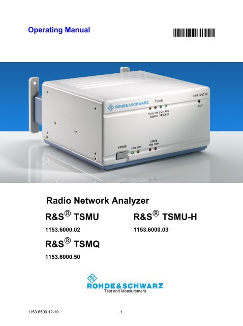
Operating Manual<br />
1153.6500.12-10<br />
<strong>Radio</strong> <strong>Network</strong> <strong>Analyzer</strong><br />
R&S <strong>®</strong> <strong>TSMU</strong><br />
1153.6000.02<br />
R&S <strong>®</strong> TSMQ<br />
1153.6000.50<br />
Test and Measurement<br />
1<br />
R&S <strong>®</strong> <strong>TSMU</strong>-H<br />
1153.6000.03
Dear Customer,<br />
R&S<strong>®</strong> is a registered trademark of <strong>Rohde</strong> & <strong>Schwarz</strong> GmbH & Co. KG.<br />
Trade names are trademarks of the owners.<br />
1153.6500.12 2 E-8
R&S <strong>®</strong> <strong>TSMU</strong>/<strong>TSMU</strong>-H/TSMQ Contents<br />
Contents<br />
Safety Instructions<br />
Certificate of Quality<br />
Support Center Address<br />
List of R&S Representatives<br />
Important Notes................................................................................................................................... 5<br />
1 General Description...............................................................................................7<br />
2 System Requirements ...........................................................................................9<br />
3 Preparations for Use............................................................................................11<br />
Unpacking the <strong>Analyzer</strong> .................................................................................................................... 11<br />
TSMx IEEE 1394 Device Driver Installation...................................................................................... 11<br />
Rack Mounting .................................................................................................................................. 11<br />
4 Putting the <strong>Analyzer</strong> into Operation...................................................................13<br />
Prerequisites ..................................................................................................................................... 13<br />
Connecting the External Devices ...................................................................................................... 14<br />
Connecting the <strong>Analyzer</strong> to the Power Supply.................................................................................. 16<br />
Power On Sequence/Idle Mode ........................................................................................................ 17<br />
Initial Connection – Windows Device Driver Installation ................................................................... 17<br />
Application Program Download/Ready Mode ................................................................................... 19<br />
Measuring Mode................................................................................................................................ 19<br />
<strong>Analyzer</strong> Reset .................................................................................................................................. 19<br />
Standby Mode ................................................................................................................................... 20<br />
5 Firmware Updates................................................................................................21<br />
Requirements .................................................................................................................................... 21<br />
Program Start .................................................................................................................................... 21<br />
6 Instrument Setup and Software Options............................................................23<br />
Program Requirements ..................................................................................................................... 23<br />
Program Start .................................................................................................................................... 23<br />
Recalling Instrument Setup ............................................................................................................... 23<br />
Recalling Enabled Software Options / Checking Device Key Installation......................................... 24<br />
Reordering Software Options............................................................................................................ 24<br />
Post-Installation of Software Options ................................................................................................ 24<br />
7 R&S ViCom Programming Interface...................................................................25<br />
General.............................................................................................................................................. 25<br />
Requirements .................................................................................................................................... 25<br />
Installation ......................................................................................................................................... 25<br />
8 Troubleshooting...................................................................................................27<br />
Means of Error Detection .................................................................................................................. 27<br />
Front Panel LEDs.................................................................................................................... 27<br />
RS-232-C Output .................................................................................................................... 27<br />
1153.6500.12 3<br />
E-8
Contents <strong>TSMU</strong>/<strong>TSMU</strong>-H/TSMQ<br />
Troubleshooting Errors Indicated by LEDs ....................................................................................... 28<br />
Temperature Failure................................................................................................................ 28<br />
Configuration State Failure ..................................................................................................... 28<br />
Power Failure .......................................................................................................................... 28<br />
Troubleshooting via the RS-232-C Interface..................................................................................... 29<br />
Tracing Power On Sequence.................................................................................................. 29<br />
Tracing Application Program Download and Ready Mode..................................................... 30<br />
Tracing Measuring Mode ........................................................................................................ 31<br />
Problems after Firmware Update ...................................................................................................... 32<br />
General ................................................................................................................................... 32<br />
How to Solve the Configuration Problem Manually: ............................................................... 32<br />
1153.6500.12 4 E-8
Grouped Safety Messages<br />
Make sure to read through and observe the following safety instructions!<br />
All plants and locations of the <strong>Rohde</strong> & <strong>Schwarz</strong> group of companies make every effort to keep the safety<br />
standard of our products up to date and to offer our customers the highest possible degree of safety. Our<br />
products and the auxiliary equipment required for them are designed and tested in accordance with the<br />
relevant safety standards. Compliance with these standards is continuously monitored by our quality<br />
assurance system. The product described here has been designed and tested in accordance with the EC<br />
Certificate of Conformity and has left the manufacturer’s plant in a condition fully complying with safety<br />
standards. To maintain this condition and to ensure safe operation, observe all instructions and warnings<br />
provided in this manual. If you have any questions regarding these safety instructions, the <strong>Rohde</strong> &<br />
<strong>Schwarz</strong> group of companies will be happy to answer them.<br />
Furthermore, it is your responsibility to use the product in an appropriate manner. This product is designed<br />
for use solely in industrial and laboratory environments or, if expressly permitted, also in the field and must<br />
not be used in any way that may cause personal injury or property damage. You are responsible if the<br />
product is used for an intention other than its designated purpose or in disregard of the manufacturer's<br />
instructions. The manufacturer shall assume no responsibility for such use of the product.<br />
The product is used for its designated purpose if it is used in accordance with its product documentation<br />
and within its performance limits (see data sheet, documentation, the following safety instructions). Using<br />
the product requires technical skills and a basic knowledge of English. It is therefore essential that only<br />
skilled and specialized staff or thoroughly trained personnel with the required skills be allowed to use the<br />
product. If personal safety gear is required for using <strong>Rohde</strong> & <strong>Schwarz</strong> products, this will be indicated at<br />
the appropriate place in the product documentation. Keep the basic safety instructions and the product<br />
documentation in a safe place and pass them on to the subsequent users.<br />
Observe<br />
product<br />
documentation<br />
Supply<br />
voltage<br />
ON/OFF<br />
Weight<br />
indication for<br />
units >18 kg<br />
Standby<br />
indication<br />
Danger of<br />
electric<br />
shock<br />
Symbols and safety labels<br />
Direct<br />
current<br />
(DC)<br />
Warning!<br />
Hot<br />
surface<br />
Alternating<br />
current (AC)<br />
PE terminal Ground<br />
Direct/alternating<br />
current (DC/AC)<br />
Ground<br />
terminal<br />
Device fully protected<br />
by double/reinforced<br />
insulation<br />
Attention!<br />
Electrostatic<br />
sensitive devices<br />
Observing the safety instructions will help prevent personal injury or damage of any kind caused by<br />
dangerous situations. Therefore, carefully read through and adhere to the following safety instructions<br />
before putting the product into operation. It is also absolutely essential to observe the additional safety<br />
instructions on personal safety that appear in relevant parts of the product documentation. In these safety<br />
instructions, the word "product" refers to all merchandise sold and distributed by the <strong>Rohde</strong> & <strong>Schwarz</strong><br />
group of companies, including instruments, systems and all accessories.<br />
1171.0000.42-04.00 Sheet 1
Grouped Safety Messages<br />
Tags and their meaning<br />
DANGER DANGER indicates a hazardous situation which, if not avoided, will result in death or<br />
serious injury.<br />
WARNING WARNING indicates a hazardous situation which, if not avoided, could result in death or<br />
serious injury.<br />
CAUTION CAUTION indicates a hazardous situation which, if not avoided, may result in minor or<br />
moderate injury.<br />
NOTICE NOTICE indicates a property damage message.<br />
In the product documentation, the word ATTENTION is used synonymously.<br />
These tags are in accordance with the standard definition for civil applications in the European Economic<br />
Area. Definitions that deviate from the standard definition may also exist in other economic areas or<br />
military applications. It is therefore essential to make sure that the tags described here are always used<br />
only in connection with the related product documentation and the related product. The use of tags in<br />
connection with unrelated products or documentation can result in misinterpretation and thus contribute to<br />
personal injury or material damage.<br />
1. The product may be operated only under the<br />
operating conditions and in the positions<br />
specified by the manufacturer. Its ventilation<br />
must not be obstructed during operation.<br />
Unless otherwise specified, the following<br />
requirements apply to <strong>Rohde</strong> & <strong>Schwarz</strong><br />
products:<br />
prescribed operating position is always with<br />
the housing floor facing down, IP protection<br />
2X, pollution severity 2, overvoltage category<br />
2, use only in enclosed spaces, max.<br />
operation altitude 2000 m above sea level,<br />
max. transport altitude 4500 m above sea<br />
level.<br />
A tolerance of ±10% shall apply to the<br />
nominal voltage and of ±5% to the nominal<br />
frequency.<br />
2. Applicable local or national safety<br />
regulations and rules for the prevention of<br />
accidents must be observed in all work<br />
performed. The product may be opened only<br />
by authorized, specially trained personnel.<br />
Prior to performing any work on the product<br />
or opening the product, the product must be<br />
disconnected from the supply network. Any<br />
adjustments, replacements of parts,<br />
maintenance or repair must be carried out<br />
only by technical personnel authorized by<br />
Basic safety instructions<br />
<strong>Rohde</strong> & <strong>Schwarz</strong>. Only original parts may<br />
be used for replacing parts relevant to safety<br />
(e.g. power switches, power transformers,<br />
fuses). A safety test must always be<br />
performed after parts relevant to safety have<br />
been replaced (visual inspection, PE<br />
conductor test, insulation resistance<br />
measurement, leakage current<br />
measurement, functional test).<br />
3. As with all industrially manufactured goods,<br />
the use of substances that induce an allergic<br />
reaction (allergens, e.g. nickel) such as<br />
aluminum cannot be generally excluded. If<br />
you develop an allergic reaction (such as a<br />
skin rash, frequent sneezing, red eyes or<br />
respiratory difficulties), consult a physician<br />
immediately to determine the cause.<br />
4. If products/components are mechanically<br />
and/or thermically processed in a manner<br />
that goes beyond their intended use,<br />
hazardous substances (heavy-metal dust<br />
such as lead, beryllium, nickel) may be<br />
released. For this reason, the product may<br />
only be disassembled, e.g. for disposal<br />
purposes, by specially trained personnel.<br />
Improper disassembly may be hazardous to<br />
your health. National waste disposal<br />
regulations must be observed.<br />
1171.0000.42-04.00 Sheet 2
5. If handling the product yields hazardous<br />
substances or fuels that must be disposed of<br />
in a special way, e.g. coolants or engine oils<br />
that must be replenished regularly, the safety<br />
instructions of the manufacturer of the<br />
hazardous substances or fuels and the<br />
applicable regional waste disposal<br />
regulations must be observed. Also observe<br />
the relevant safety instructions in the product<br />
documentation.<br />
6. Depending on the function, certain products<br />
such as RF radio equipment can produce an<br />
elevated level of electromagnetic radiation.<br />
Considering that unborn life requires<br />
increased protection, pregnant women<br />
should be protected by appropriate<br />
measures. Persons with pacemakers may<br />
also be endangered by electromagnetic<br />
radiation. The employer/operator is required<br />
to assess workplaces where there is a<br />
special risk of exposure to radiation and, if<br />
necessary, take measures to avert the<br />
danger.<br />
7. Operating the products requires special<br />
training and intense concentration. Make<br />
certain that persons who use the products<br />
are physically, mentally and emotionally fit<br />
enough to handle operating the products;<br />
otherwise injuries or material damage may<br />
occur. It is the responsibility of the employer<br />
to select suitable personnel for operating the<br />
products.<br />
8. Prior to switching on the product, it must be<br />
ensured that the nominal voltage setting on<br />
the product matches the nominal voltage of<br />
the AC supply network. If a different voltage<br />
is to be set, the power fuse of the product<br />
may have to be changed accordingly.<br />
9. In the case of products of safety class I with<br />
movable power cord and connector,<br />
operation is permitted only on sockets with<br />
earthing contact and protective earth<br />
connection.<br />
10. Intentionally breaking the protective earth<br />
connection either in the feed line or in the<br />
product itself is not permitted. Doing so can<br />
result in the danger of an electric shock from<br />
the product. If extension cords or connector<br />
strips are implemented, they must be<br />
checked on a regular basis to ensure that<br />
they are safe to use.<br />
11. If the product has no power switch for<br />
disconnection from the AC supply, the plug<br />
Grouped Safety Messages<br />
of the connecting cable is regarded as the<br />
disconnecting device. In such cases, it must<br />
be ensured that the power plug is easily<br />
reachable and accessible at all times<br />
(corresponding to the length of connecting<br />
cable, approx. 2 m). Functional or electronic<br />
switches are not suitable for providing<br />
disconnection from the AC supply. If<br />
products without power switches are<br />
integrated in racks or systems, a<br />
disconnecting device must be provided at<br />
the system level.<br />
12. Never use the product if the power cable is<br />
damaged. Check the power cable on a<br />
regular basis to ensure that it is in proper<br />
operating condition. By taking appropriate<br />
safety measures and carefully laying the<br />
power cable, ensure that the cable cannot be<br />
damaged and that no one can be hurt by e.g.<br />
tripping over the cable or suffering an electric<br />
shock.<br />
13. The product may be operated only from<br />
TN/TT supply networks fused with max. 16 A<br />
(higher fuse only after consulting with the<br />
<strong>Rohde</strong> & <strong>Schwarz</strong> group of companies).<br />
14. Do not insert the plug into sockets that are<br />
dusty or dirty. Insert the plug firmly and all<br />
the way into the socket. Otherwise, this can<br />
result in sparks, fire and/or injuries.<br />
15. Do not overload any sockets, extension<br />
cords or connector strips; doing so can<br />
cause fire or electric shocks.<br />
16. For measurements in circuits with voltages<br />
Vrms > 30 V, suitable measures (e.g.<br />
appropriate measuring equipment, fusing,<br />
current limiting, electrical separation,<br />
insulation) should be taken to avoid any<br />
hazards.<br />
17. Ensure that the connections with information<br />
technology equipment comply with IEC<br />
950/EN 60950.<br />
18. Unless expressly permitted, never remove<br />
the cover or any part of the housing while the<br />
product is in operation. Doing so will expose<br />
circuits and components and can lead to<br />
injuries, fire or damage to the product.<br />
19. If a product is to be permanently installed,<br />
the connection between the PE terminal on<br />
site and the product's PE conductor must be<br />
made first before any other connection is<br />
made. The product may be installed and<br />
connected only by a license electrician.<br />
1171.0000.42-04.00 Sheet 3
20. For permanently installed equipment without<br />
built-in fuses, circuit breakers or similar<br />
protective devices, the supply circuit must be<br />
fused in such a way that suitable protection<br />
is provided for users and products.<br />
21. Do not insert any objects into the openings in<br />
the housing that are not designed for this<br />
purpose. Never pour any liquids onto or into<br />
the housing. This can cause short circuits<br />
inside the product and/or electric shocks, fire<br />
or injuries.<br />
22. Use suitable overvoltage protection to<br />
ensure that no overvoltage (such as that<br />
caused by a thunderstorm) can reach the<br />
product. Otherwise the operating personnel<br />
will be endangered by electric shocks.<br />
23. <strong>Rohde</strong> & <strong>Schwarz</strong> products are not protected<br />
against penetration of liquids, unless<br />
otherwise specified (see also safety<br />
instruction 1.). If this is not taken into<br />
account, there exists the danger of electric<br />
shock for the user or damage to the product,<br />
which can also lead to personal injury.<br />
24. Never use the product under conditions in<br />
which condensation has formed or can form<br />
in or on the product, e.g. if the product was<br />
moved from a cold to a warm environment.<br />
25. Do not close any slots or openings on the<br />
product, since they are necessary for<br />
ventilation and prevent the product from<br />
overheating. Do not place the product on soft<br />
surfaces such as sofas or rugs or inside a<br />
closed housing, unless this is well ventilated.<br />
26. Do not place the product on heat-generating<br />
devices such as radiators or fan heaters.<br />
The temperature of the environment must<br />
not exceed the maximum temperature<br />
specified in the data sheet.<br />
27. Batteries and storage batteries must not be<br />
exposed to high temperatures or fire. Keep<br />
batteries and storage batteries away from<br />
children. Do not short-circuit batteries and<br />
storage batteries.<br />
If batteries or storage batteries are<br />
improperly replaced, this can cause an<br />
explosion (warning: lithium cells). Replace<br />
the battery or storage battery only with the<br />
matching <strong>Rohde</strong> & <strong>Schwarz</strong> type (see spare<br />
parts list). Batteries and storage batteries<br />
must be recycled and kept separate from<br />
residual waste. Batteries and storage<br />
batteries that contain lead, mercury or<br />
cadmium are hazardous waste. Observe the<br />
Grouped Safety Messages<br />
national regulations regarding waste<br />
disposal and recycling.<br />
28. Please be aware that in the event of a fire,<br />
toxic substances (gases, liquids etc.) that<br />
may be hazardous to your health may<br />
escape from the product.<br />
29. The product can be very heavy. Be careful<br />
when moving it to avoid back or other<br />
physical injuries.<br />
30. Do not place the product on surfaces,<br />
vehicles, cabinets or tables that for reasons<br />
of weight or stability are unsuitable for this<br />
purpose. Always follow the manufacturer's<br />
installation instructions when installing the<br />
product and fastening it to objects or<br />
structures (e.g. walls and shelves).<br />
31. Handles on the products are designed<br />
exclusively for personnel to hold or carry the<br />
product. It is therefore not permissible to use<br />
handles for fastening the product to or on<br />
means of transport such as cranes, fork lifts,<br />
wagons, etc. The user is responsible for<br />
securely fastening the products to or on the<br />
means of transport and for observing the<br />
safety regulations of the manufacturer of the<br />
means of transport. Noncompliance can<br />
result in personal injury or material damage.<br />
32. If you use the product in a vehicle, it is the<br />
sole responsibility of the driver to drive the<br />
vehicle safely. Adequately secure the<br />
product in the vehicle to prevent injuries or<br />
other damage in the event of an accident.<br />
Never use the product in a moving vehicle if<br />
doing so could distract the driver of the<br />
vehicle. The driver is always responsible for<br />
the safety of the vehicle. The manufacturer<br />
assumes no responsibility for accidents or<br />
collisions.<br />
33. If a laser product (e.g. a CD/DVD drive) is<br />
integrated in a <strong>Rohde</strong> & <strong>Schwarz</strong> product, do<br />
not use any other settings or functions than<br />
those described in the product documentation.<br />
Otherwise this may be hazardous to<br />
your health, since the laser beam can cause<br />
irreversible damage to your eyes. Never try<br />
to take such products apart, and never look<br />
into the laser beam.<br />
34. Prior to cleaning, disconnect the product<br />
from the AC supply. Use a soft, non-linting<br />
cloth to clean the product. Never use<br />
chemical cleaning agents such as alcohol,<br />
acetone or diluent for cellulose lacquers.<br />
1171.0000.42-04.00 Sheet 4
Informaciones elementales de seguridad<br />
¡Es imprescindible leer y observar las siguientes instrucciones e informaciones<br />
de seguridad!<br />
El principio del grupo de empresas <strong>Rohde</strong> & <strong>Schwarz</strong> consiste en tener nuestros productos siempre al día<br />
con los estándares de seguridad y de ofrecer a nuestros clientes el máximo grado de seguridad. Nuestros<br />
productos y todos los equipos adicionales son siempre fabricados y examinados según las normas de<br />
seguridad vigentes. Nuestra sección de gestión de la seguridad de calidad controla constantemente que<br />
sean cumplidas estas normas. El presente producto ha sido fabricado y examinado según el comprobante<br />
de conformidad adjunto según las normas de la CE y ha salido de nuestra planta en estado impecable<br />
según los estándares técnicos de seguridad. Para poder preservar este estado y garantizar un<br />
funcionamiento libre de peligros, el usuario deberá atenerse a todas las indicaciones, informaciones de<br />
seguridad y notas de alerta. El grupo de empresas <strong>Rohde</strong> & <strong>Schwarz</strong> está siempre a su disposición en<br />
caso de que tengan preguntas referentes a estas informaciones de seguridad.<br />
Además queda en la responsabilidad del usuario utilizar el producto en la forma debida. Este producto<br />
está destinado exclusivamente al uso en la industria y el laboratorio o, si ha sido expresamente<br />
autorizado, para aplicaciones de campo y de ninguna manera deberá ser utilizado de modo que alguna<br />
persona/cosa pueda sufrir daño. El uso del producto fuera de sus fines definidos o despreciando las<br />
informaciones de seguridad del fabricante queda en la responsabilidad del usuario. El fabricante no se<br />
hace en ninguna forma responsable de consecuencias a causa del mal uso del producto.<br />
Se parte del uso correcto del producto para los fines definidos si el producto es utilizado dentro de las<br />
instrucciones de la correspondiente documentación de producto y dentro del margen de rendimiento<br />
definido (ver hoja de datos, documentación, informaciones de seguridad que siguen). El uso del producto<br />
hace necesarios conocimientos profundos y conocimientos básicas del idioma inglés. Por eso se debe<br />
tener en cuenta que el producto sólo pueda ser operado por personal especializado o personas<br />
minuciosamente instruidas con las capacidades correspondientes. Si fuera necesaria indumentaria de<br />
seguridad para el uso de productos de R&S, encontrará la información debida en la documentación del<br />
producto en el capítulo correspondiente. Guarde bien las informaciones de seguridad elementales, así<br />
como la documentación del producto y entréguela a usuarios posteriores.<br />
Ver<br />
documentación<br />
de<br />
producto<br />
Potencia EN<br />
MARCHA/PARADA<br />
Informaciones<br />
para<br />
maquinaria<br />
con un peso<br />
de > 18kg<br />
Indicación<br />
Stand-by<br />
Símbolos y definiciones de seguridad<br />
Peligro de<br />
golpe de<br />
corriente<br />
Corriente<br />
continua DC<br />
¡Advertencia!<br />
Superficie<br />
caliente<br />
Corriente<br />
alterna AC<br />
Conexión a<br />
conductor<br />
protector<br />
Conexión<br />
a tierra<br />
Corriente continua/alterna<br />
DC/AC<br />
Conexión<br />
a masa<br />
conductora<br />
¡Cuidado!<br />
Elementos de<br />
construcción con<br />
peligro de carga<br />
electroestática<br />
El aparato está protegido en<br />
su totalidad por un<br />
aislamiento de doble refuerzo<br />
1171.0000.42-04.00 Sheet 5
Informaciones elementales de seguridad<br />
Tener en cuenta las informaciones de seguridad sirve para tratar de evitar daños y peligros de toda clase.<br />
Es necesario de que se lean las siguientes informaciones de seguridad concienzudamente y se tengan en<br />
cuenta debidamente antes de la puesta en funcionamiento del producto. También deberán ser tenidas en<br />
cuenta las informaciones para la protección de personas que encontrarán en el capítulo correspondiente<br />
de la documentación de producto y que también son obligatorias de seguir. En las informaciones de<br />
seguridad actuales hemos juntado todos los objetos vendidos por el grupo de empresas <strong>Rohde</strong> &<br />
<strong>Schwarz</strong> bajo la denominación de „producto“, entre ellos también aparatos, instalaciones así como toda<br />
clase de accesorios.<br />
Palabras de señal y su significado<br />
PELIGRO Identifica un peligro directo con riesgo elevado de provocar muerte o<br />
lesiones de gravedad si no se toman las medidas oportunas.<br />
ADVERTENCIA Identifica un posible peligro con riesgo medio de provocar muerte o<br />
lesiones (de gravedad) si no se toman las medidas oportunas.<br />
ATENCIÓN Identifica un peligro con riesgo reducido de provocar lesiones de<br />
gravedad media o leve si no se toman las medidas oportunas.<br />
AVISO Indica la posibilidad de utilizar mal el producto y a consecuencia<br />
dañarlo.<br />
En la documentación del producto se emplea de forma sinónima el<br />
término CUIDADO.<br />
Las palabras de señal corresponden a la definición habitual para aplicaciones civiles en el área<br />
económica europea. Pueden existir definiciones diferentes a esta definición en otras áreas económicas o<br />
en aplicaciones militares. Por eso se deberá tener en cuenta que las palabras de señal aquí descritas<br />
sean utilizadas siempre solamente en combinación con la correspondiente documentación de producto y<br />
solamente en combinación con el producto correspondiente. La utilización de las palabras de señal en<br />
combinación con productos o documentaciones que no les correspondan puede llevar a<br />
malinterpretaciones y tener por consecuencia daños en personas u objetos.<br />
1. El producto solamente debe ser utilizado<br />
según lo indicado por el fabricante referente a<br />
la situación y posición de funcionamiento sin<br />
que se obstruya la ventilación. Si no se<br />
convino de otra manera, es para los productos<br />
R&S válido lo que sigue:<br />
como posición de funcionamiento se define<br />
por principio la posición con el suelo de la caja<br />
para abajo, modo de protección IP 2X, grado<br />
de suciedad 2, categoría de sobrecarga<br />
eléctrica 2, utilizar solamente en estancias<br />
interiores, utilización hasta 2000 m sobre el<br />
nivel del mar, transporte hasta 4.500 m sobre<br />
el nivel del mar.<br />
Se aplicará una tolerancia de ±10% sobre el<br />
voltaje nominal y de ±5% sobre la frecuencia<br />
nominal.<br />
2. En todos los trabajos deberán ser tenidas en<br />
cuenta las normas locales de seguridad de<br />
Informaciones de seguridad elementales<br />
trabajo y de prevención de accidentes. El<br />
producto solamente debe de ser abierto por<br />
personal especializado autorizado. Antes de<br />
efectuar trabajos en el producto o abrirlo<br />
deberá este ser desconectado de la corriente.<br />
El ajuste, el cambio de partes, la manutención<br />
y la reparación deberán ser solamente<br />
efectuadas por electricistas autorizados por<br />
R&S. Si se reponen partes con importancia<br />
para los aspectos de seguridad (por ejemplo<br />
el enchufe, los transformadores o los fusibles),<br />
solamente podrán ser sustituidos por partes<br />
originales. Después de cada recambio de<br />
partes elementales para la seguridad deberá<br />
ser efectuado un control de seguridad (control<br />
a primera vista, control de conductor protector,<br />
medición de resistencia de aislamiento,<br />
medición de la corriente conductora, control<br />
de funcionamiento).<br />
1171.0000.42-04.00 Sheet 6
3. Como en todo producto de fabricación<br />
industrial no puede ser excluido en general de<br />
que se produzcan al usarlo elementos que<br />
puedan generar alergias, los llamados<br />
elementos alergénicos (por ejemplo el<br />
níquel). Si se producieran en el trato con<br />
productos R&S reacciones alérgicas, como<br />
por ejemplo urticaria, estornudos frecuentes,<br />
irritación de la conjuntiva o dificultades al<br />
respirar, se deberá consultar inmediatamente<br />
a un médico para averiguar los motivos de<br />
estas reacciones.<br />
4. Si productos / elementos de construcción son<br />
tratados fuera del funcionamiento definido de<br />
forma mecánica o térmica, pueden generarse<br />
elementos peligrosos (polvos de sustancia de<br />
metales pesados como por ejemplo plomo,<br />
berilio, níquel). La partición elemental del<br />
producto, como por ejemplo sucede en el<br />
tratamiento de materias residuales, debe de<br />
ser efectuada solamente por personal<br />
especializado para estos tratamientos. La<br />
partición elemental efectuada<br />
inadecuadamente puede generar daños para<br />
la salud. Se deben tener en cuenta las<br />
directivas nacionales referentes al tratamiento<br />
de materias residuales.<br />
5. En el caso de que se produjeran agentes de<br />
peligro o combustibles en la aplicación del<br />
producto que debieran de ser transferidos a<br />
un tratamiento de materias residuales, como<br />
por ejemplo agentes refrigerantes que deben<br />
ser repuestos en periodos definidos, o aceites<br />
para motores, deberán ser tenidas en cuenta<br />
las prescripciones de seguridad del fabricante<br />
de estos agentes de peligro o combustibles y<br />
las regulaciones regionales para el tratamiento<br />
de materias residuales. Cuiden también de<br />
tener en cuenta en caso dado las<br />
prescripciones de seguridad especiales en la<br />
descripción del producto.<br />
6. Ciertos productos, como por ejemplo las<br />
instalaciones de radiocomunicación RF,<br />
pueden a causa de su función natural, emitir<br />
una radiación electromagnética aumentada.<br />
En vista a la protección de la vida en<br />
desarrollo deberían ser protegidas personas<br />
embarazadas debidamente. También las<br />
personas con un bypass pueden correr peligro<br />
a causa de la radiación electromagnética.<br />
Informaciones elementales de seguridad<br />
El empresario/usuario está comprometido a<br />
valorar y señalar áreas de trabajo en las que<br />
se corra un riesgo aumentado de exposición a<br />
radiaciones para evitar riesgos.<br />
7. La utilización de los productos requiere<br />
instrucciones especiales y una alta<br />
concentración en el manejo. Debe de ponerse<br />
por seguro de que las personas que manejen<br />
los productos estén a la altura de los<br />
requerimientos necesarios referente a sus<br />
aptitudes físicas, psíquicas y emocionales, ya<br />
que de otra manera no se pueden excluir<br />
lesiones o daños de objetos. El empresario<br />
lleva la responsabilidad de seleccionar el<br />
personal usuario apto para el manejo de los<br />
productos.<br />
8. Antes de la puesta en marcha del producto se<br />
deberá tener por seguro de que la tensión<br />
preseleccionada en el producto equivalga a la<br />
del la red de distribución. Si es necesario<br />
cambiar la preselección de la tensión también<br />
se deberán en caso dabo cambiar los fusibles<br />
correspondientes del producto.<br />
9. Productos de la clase de seguridad I con<br />
alimentación móvil y enchufe individual de<br />
producto solamente deberán ser conectados<br />
para el funcionamiento a tomas de corriente<br />
de contacto de seguridad y con conductor<br />
protector conectado.<br />
10. Queda prohibida toda clase de interrupción<br />
intencionada del conductor protector, tanto en<br />
la toma de corriente como en el mismo<br />
producto. Puede tener como consecuencia el<br />
peligro de golpe de corriente por el producto.<br />
Si se utilizaran cables o enchufes de<br />
extensión se deberá poner al seguro que es<br />
controlado su estado técnico de seguridad.<br />
11. Si el producto no está equipado con un<br />
interruptor para desconectarlo de la red, se<br />
deberá considerar el enchufe del cable de<br />
distribución como interruptor. En estos casos<br />
deberá asegurar de que el enchufe sea de<br />
fácil acceso y nabejo (según la medida del<br />
cable de distribución, aproximadamente 2 m).<br />
Los interruptores de función o electrónicos no<br />
son aptos para el corte de la red eléctrica. Si<br />
los productos sin interruptor están integrados<br />
en bastidores o instalaciones, se deberá<br />
instalar el interruptor al nivel de la instalación.<br />
1171.0000.42-04.00 Sheet 7
12. No utilice nunca el producto si está dañado el<br />
cable eléctrico. Compruebe regularmente el<br />
correcto estado de los cables de conexión a<br />
red. Asegure a través de las medidas de<br />
protección y de instalación adecuadas de que<br />
el cable de eléctrico no pueda ser dañado o<br />
de que nadie pueda ser dañado por él, por<br />
ejemplo al tropezar o por un golpe de<br />
corriente.<br />
13. Solamente está permitido el funcionamiento<br />
en redes de distribución TN/TT aseguradas<br />
con fusibles de como máximo 16 A (utilización<br />
de fusibles de mayor amperaje sólo previa<br />
consulta con el grupo de empresas <strong>Rohde</strong> &<br />
Informaciones elementales de seguridad<br />
20. En caso de que los productos que son<br />
instalados fijamente en un lugar sean sin<br />
protector implementado, autointerruptor o<br />
similares objetos de protección, el circuito de<br />
suministro de corriente deberá estar protegido<br />
de manera que usuarios y productos estén<br />
suficientemente protegidos.<br />
21. Por favor, no introduzca ningún objeto que no<br />
esté destinado a ello en los orificios de la caja<br />
del aparato. No vierta nunca ninguna clase de<br />
líquidos sobre o en la caja. Esto puede<br />
producir cortocircuitos en el producto y/o<br />
puede causar golpes de corriente, fuego o<br />
heridas.<br />
<strong>Schwarz</strong>). 22. Asegúrese con la protección adecuada de que<br />
14. Nunca conecte el enchufe en tomas de<br />
corriente sucias o llenas de polvo. Introduzca<br />
el enchufe por completo y fuertemente en la<br />
toma de corriente. Si no tiene en<br />
consideración estas indicaciones se arriesga a<br />
no pueda originarse en el producto una<br />
sobrecarga por ejemplo a causa de una<br />
tormenta. Si no se verá el personal que lo<br />
utilice expuesto al peligro de un golpe de<br />
corriente.<br />
que se originen chispas, fuego y/o heridas. 23. Los productos R&S no están protegidos contra<br />
15. No sobrecargue las tomas de corriente, los<br />
cables de extensión o los enchufes de<br />
extensión ya que esto pudiera causar fuego o<br />
golpes de corriente.<br />
16. En las mediciones en circuitos de corriente<br />
con una tensión de entrada de Ueff > 30 V se<br />
deberá tomar las precauciones debidas para<br />
impedir cualquier peligro (por ejemplo medios<br />
de medición adecuados, seguros, limitación<br />
de tensión, corte protector, aislamiento etc.).<br />
17. En caso de conexión con aparatos de la<br />
técnica informática se deberá tener en cuenta<br />
que estos cumplan los requisitos del estándar<br />
IEC950/EN60950.<br />
18. A menos que esté permitido expresamente, no<br />
retire nunca la tapa ni componentes de la<br />
carcasa mientras el producto esté en servicio.<br />
Esto pone a descubierto los cables y<br />
componentes eléctricos y puede causar<br />
heridas, fuego o daños en el producto.<br />
19. Si un producto es instalado fijamente en un<br />
lugar, se deberá primero conectar el conductor<br />
protector fijo con el conductor protector del<br />
aparato antes de hacer cualquier otra<br />
conexión. La instalación y la conexión deberán<br />
ser efectuadas por un electricista<br />
especializado.<br />
líquidos si no es que exista otra indicación, ver<br />
también punto 1. Si no se tiene en cuenta esto<br />
se arriesga el peligro de golpe de corriente<br />
para el usuario o de daños en el producto lo<br />
cual también puede llevar al peligro de<br />
personas.<br />
24. No utilice el producto bajo condiciones en las<br />
que pueda producirse y se hayan producido<br />
líquidos de condensación en o dentro del<br />
producto como por ejemplo cuando se<br />
desplaza el producto de un lugar frío a un<br />
lugar caliente.<br />
25. Por favor no cierre ninguna ranura u orificio<br />
del producto, ya que estas son necesarias<br />
para la ventilación e impiden que el producto<br />
se caliente demasiado. No pongan el producto<br />
encima de materiales blandos como por<br />
ejemplo sofás o alfombras o dentro de una<br />
caja cerrada, si esta no está suficientemente<br />
ventilada.<br />
26. No ponga el producto sobre aparatos que<br />
produzcan calor, como por ejemplo radiadores<br />
o calentadores. La temperatura ambiental no<br />
debe superar la temperatura máxima<br />
especificada en la hoja de datos.<br />
1171.0000.42-04.00 Sheet 8
27. Baterías y acumuladores no deben de ser<br />
expuestos a temperaturas altas o al fuego.<br />
Guardar baterías y acumuladores fuera del<br />
alcance de los niños. No cortocircuitar<br />
baterías ni acumuladores. Si las baterías o los<br />
acumuladores no son cambiados con la<br />
debida atención existirá peligro de explosión<br />
(atención células de litio). Cambiar las<br />
baterías o los acumuladores solamente por los<br />
del tipo R&S correspondiente (ver lista de<br />
piezas de recambio). Las baterías y<br />
acumuladores deben reutilizarse y no deben<br />
acceder a los vertederos. Las baterías y<br />
acumuladores que contienen plomo, mercurio<br />
o cadmio deben tratarse como residuos<br />
especiales. Respete en esta relación las<br />
normas nacionales de evacuación y reciclaje.<br />
28. Por favor tengan en cuenta que en caso de un<br />
incendio pueden desprenderse del producto<br />
agentes venenosos (gases, líquidos etc.) que<br />
pueden generar daños a la salud.<br />
29. El producto puede poseer un peso elevado.<br />
Muévalo con cuidado para evitar lesiones en<br />
la espalda u otras partes corporales.<br />
30. No sitúe el producto encima de superficies,<br />
vehículos, estantes o mesas, que por sus<br />
características de peso o de estabilidad no<br />
sean aptas para él. Siga siempre las<br />
instrucciones de instalación del fabricante<br />
cuando instale y asegure el producto en<br />
objetos o estructuras (por ejemplo paredes y<br />
estantes).<br />
31. Las asas instaladas en los productos sirven<br />
solamente de ayuda para el manejo que<br />
solamente está previsto para personas. Por<br />
eso no está permitido utilizar las asas para la<br />
sujeción en o sobre medios de transporte<br />
como por ejemplo grúas, carretillas elevadoras<br />
Informaciones elementales de seguridad<br />
de horquilla, carros etc. El usuario es<br />
responsable de que los productos sean<br />
sujetados de forma segura a los medios de<br />
transporte y de que las prescripciones de<br />
seguridad del fabricante de los medios de<br />
transporte sean observadas. En caso de que<br />
no se tengan en cuenta pueden causarse<br />
daños en personas y objetos.<br />
32. Si llega a utilizar el producto dentro de un<br />
vehículo, queda en la responsabilidad<br />
absoluta del conductor que conducir el<br />
vehículo de manera segura. Asegure el<br />
producto dentro del vehículo debidamente<br />
para evitar en caso de un accidente las<br />
lesiones u otra clase de daños. No utilice<br />
nunca el producto dentro de un vehículo en<br />
movimiento si esto pudiera distraer al<br />
conductor. Siempre queda en la<br />
responsabilidad absoluta del conductor la<br />
seguridad del vehículo. El fabricante no<br />
asumirá ninguna clase de responsabilidad por<br />
accidentes o colisiones.<br />
33. Dado el caso de que esté integrado un<br />
producto de láser en un producto R&S (por<br />
ejemplo CD/DVD-ROM) no utilice otras<br />
instalaciones o funciones que las descritas en<br />
la documentación de producto. De otra<br />
manera pondrá en peligro su salud, ya que el<br />
rayo láser puede dañar irreversiblemente sus<br />
ojos. Nunca trate de descomponer estos<br />
productos. Nunca mire dentro del rayo láser.<br />
34. Antes de proceder a la limpieza, desconecte el<br />
producto de la red. Realice la limpieza con un<br />
paño suave, que no se deshilache. No utilice<br />
de ninguna manera agentes limpiadores<br />
químicos como, por ejemplo, alcohol, acetona<br />
o nitrodiluyente.<br />
1171.0000.42-04.00 Sheet 9
Customer Information Regarding Product Disposal<br />
The German Electrical and Electronic Equipment (ElektroG) Act is an implementation of<br />
the following EC directives:<br />
2002/96/EC on waste electrical and electronic equipment (WEEE) and<br />
2002/95/EC on the restriction of the use of certain hazardous substances in<br />
electrical and electronic equipment (RoHS).<br />
1171.0200.52-01.01<br />
Product labeling in accordance with EN 50419<br />
Once the lifetime of a product has ended, this product must not be disposed of<br />
in the standard domestic refuse. Even disposal via the municipal collection<br />
points for waste electrical and electronic equipment is not permitted.<br />
<strong>Rohde</strong> & <strong>Schwarz</strong> GmbH & Co. KG has developed a disposal concept for the<br />
environmental-friendly disposal or recycling of waste material and fully assumes its<br />
obligation as a producer to take back and dispose of electrical and electronic waste<br />
in accordance with the ElektroG Act.<br />
Please contact your local service representative to dispose of the product.
1171.0200.11-01.00<br />
DIN EN ISO 9001 : 2000<br />
DIN EN 9100 : 2003<br />
DIN EN ISO 14001 : 1996<br />
Sehr geehrter Kunde,<br />
Sie haben sich für den Kauf eines<br />
<strong>Rohde</strong> & <strong>Schwarz</strong>-Produktes entschieden.<br />
Hiermit erhalten Sie ein nach<br />
modernsten Fertigungsmethoden<br />
hergestelltes Produkt. Es wurde nach<br />
den Regeln unseres Managementsystems<br />
entwickelt, gefertigt und<br />
geprüft.<br />
Das <strong>Rohde</strong> & <strong>Schwarz</strong> Managementsystem<br />
ist zertifiziert nach:<br />
DIN EN ISO 9001:2000<br />
DIN EN 9100:2003<br />
DIN EN ISO 14001:1996<br />
Certified Quality System<br />
DQS REG. NO 001954 QM/ST UM<br />
QUALITÄTSZERTIFIKAT CERTIFICATE OF QUALITY CERTIFICAT DE QUALITÉ<br />
Dear Customer,<br />
you have decided to buy a <strong>Rohde</strong> &<br />
<strong>Schwarz</strong> product. You are thus assured<br />
of receiving a product that is<br />
manufactured using the most modern<br />
methods available. This product was<br />
developed, manufactured and tested<br />
in compliance with our quality management<br />
system standards.<br />
The <strong>Rohde</strong> & <strong>Schwarz</strong> quality management<br />
system is certified according to:<br />
DIN EN ISO 9001:2000<br />
DIN EN 9100:2003<br />
DIN EN ISO 14001:1996<br />
Cher Client,<br />
vous avez choisi d‘acheter un produit<br />
<strong>Rohde</strong> & <strong>Schwarz</strong>. Vous disposez<br />
donc d‘un produit fabriqué d‘après<br />
les méthodes les plus avancées. Le<br />
développement, la fabrication et les<br />
tests respectent nos normes de gestion<br />
qualité.<br />
Le système de gestion qualité de<br />
<strong>Rohde</strong> & <strong>Schwarz</strong> a été homologué<br />
conformément aux normes:<br />
DIN EN ISO 9001:2000<br />
DIN EN 9100:2003<br />
DIN EN ISO 14001:1996
Certificate No.: 2003-40<br />
This is to certify that:<br />
Equipment type Stock No. Designation<br />
EC Certificate of Conformity<br />
<strong>TSMU</strong> 1153.6000.02 <strong>Radio</strong> <strong>Network</strong> <strong>Analyzer</strong><br />
<strong>TSMU</strong>-H 1153.6000.03<br />
TSML-W 1153.6000.11<br />
TSML-C 1153.6000.12<br />
TSML-G 1153.6000.13<br />
TSML-CW 1153.6000.15<br />
TSMQ 1153.6000.50 Quad Tec Drive Test Receiver<br />
complies with the provisions of the Directive of the Council of the European Union on the<br />
approximation of the laws of the Member States<br />
- relating to electrical equipment for use within defined voltage limits<br />
(73/23/EEC revised by 93/68/EEC)<br />
- relating to electromagnetic compatibility<br />
(89/336/EEC revised by 91/263/EEC, 92/31/EEC, 93/68/EEC)<br />
Conformity is proven by compliance with the following standards:<br />
EN61010-1 : 2001-12<br />
EN61326 : 1997 + A1 : 1998 + A2 : 2001 + A3 : 2003<br />
EN55011 : 1998 + A1 : 1999 + A2 : 2002<br />
For the assessment of electromagnetic compatibility, the limits of radio interference for Class<br />
B equipment as well as the immunity to interference for operation in industry have been used<br />
as a basis.<br />
The product complies with the requirements of the Directive relating to the radio interference<br />
of vehicles (72/245/EEC adapted by 2004/104/EC, 2005/49/EC, 2005/83/EC, 2006/28/EC,<br />
after-market equipment in accordance with Annex I, paragraph 3.2.9 of the Directive); proof of<br />
compliance provided by the measurements as described in Annex I, paragraphs 6.5, 6.6, 6.8,<br />
6.9.<br />
Affixing the EC conformity mark as from 2003<br />
ROHDE & SCHWARZ GmbH & Co. KG<br />
Mühldorfstr. 15, D-81671 München<br />
Munich, 2006-12-13 Central Quality Management FS-QZ / Radde<br />
1153.6000.02 CE E-5
Customer Support<br />
Technical support – where and when you need it<br />
For quick, expert help with any <strong>Rohde</strong> & <strong>Schwarz</strong> equipment, contact one of our Customer Support<br />
Centers. A team of highly qualified engineers provides telephone support and will work with you to find a<br />
solution to your query on any aspect of the operation, programming or applications of <strong>Rohde</strong> & <strong>Schwarz</strong><br />
equipment.<br />
Up-to-date information and upgrades<br />
To keep your instrument up-to-date and to be informed about new application notes related to your<br />
instrument, please send an e-mail to the Customer Support Center stating your instrument and your wish.<br />
We will take care that you will get the right information.<br />
USA & Canada Monday to Friday (except US public holidays)<br />
8:00 AM – 8:00 PM Eastern Standard Time (EST)<br />
1171.0200.22-03.00<br />
Tel. from USA 888-test-rsa (888-837-8772) (opt 2)<br />
From outside USA +1 410 910 7800 (opt 2)<br />
Fax +1 410 910 7801<br />
E-mail CustomerSupport@rohde-schwarz.com<br />
East Asia Monday to Friday (except Singaporean public holidays)<br />
8:30 AM – 6:00 PM Singapore Time (SGT)<br />
Tel. +65 6 513 0488<br />
Fax +65 6 846 1090<br />
E-mail CustomerSupport@rohde-schwarz.com<br />
Rest of the World Monday to Friday (except German public holidays)<br />
08:00 – 17:00 Central European Time (CET)<br />
Tel. from Europe +49 (0) 180 512 42 42*<br />
From outside Europe +49 89 4129 13776<br />
Fax +49 (0) 89 41 29 637 78<br />
E-mail CustomerSupport@rohde-schwarz.com<br />
* 0.14 €/Min within the German fixed-line telephone network, varying prices<br />
for the mobile telephone network and in different countries.
12 Address List<br />
Headquarters, Plants and Subsidiaries<br />
Headquarters<br />
ROHDE&SCHWARZ GmbH & Co. KG<br />
Mühldorfstraße 15 · D-81671 München<br />
P.O.Box 80 14 69 · D-81614 München<br />
Plants<br />
ROHDE&SCHWARZ Messgerätebau GmbH<br />
Riedbachstraße 58 · D-87700 Memmingen<br />
P.O.Box 16 52 · D-87686 Memmingen<br />
ROHDE&SCHWARZ GmbH & Co. KG<br />
Werk Teisnach<br />
Kaikenrieder Straße 27 · D-94244 Teisnach<br />
P.O.Box 11 49 · D-94240 Teisnach<br />
ROHDE&SCHWARZ závod<br />
Vimperk, s.r.o.<br />
Location Spidrova 49<br />
CZ-38501 Vimperk<br />
ROHDE&SCHWARZ GmbH & Co. KG<br />
Dienstleistungszentrum Köln<br />
Graf-Zeppelin-Straße 18 · D-51147 Köln<br />
P.O.Box 98 02 60 · D-51130 Köln<br />
Subsidiaries<br />
R&S BICK Mobilfunk GmbH<br />
Fritz-Hahne-Str. 7 · D-31848 Bad Münder<br />
P.O.Box 20 02 · D-31844 Bad Münder<br />
ROHDE&SCHWARZ FTK GmbH<br />
Wendenschloßstraße 168, Haus 28<br />
D-12557 Berlin<br />
ROHDE&SCHWARZ SIT GmbH<br />
Am Studio 3<br />
D-12489 Berlin<br />
R&S Systems GmbH<br />
Graf-Zeppelin-Straße 18<br />
D-51147 Köln<br />
GEDIS GmbH<br />
Sophienblatt 100<br />
D-24114 Kiel<br />
HAMEG Instruments GmbH<br />
Industriestraße 6<br />
D-63533 Mainhausen<br />
1171.0200.42-02.00<br />
Phone +49 (89) 41 29-0<br />
Fax +49 (89) 41 29-121 64<br />
info.rs@rohde-schwarz.com<br />
Phone +49 (83 31) 1 08-0<br />
+49 (83 31) 1 08-1124<br />
info.rsmb@rohde-schwarz.com<br />
Phone +49 (99 23) 8 50-0<br />
Fax +49 (99 23) 8 50-174<br />
info.rsdts@rohde-schwarz.com<br />
Phone +420 (388) 45 21 09<br />
Fax +420 (388) 45 21 13<br />
Phone +49 (22 03) 49-0<br />
Fax +49 (22 03) 49 51-229<br />
info.rsdc@rohde-schwarz.com<br />
service.rsdc@rohde-schwarz.com<br />
Phone +49 (50 42) 9 98-0<br />
Fax +49 (50 42) 9 98-105<br />
info.bick@rohde-schwarz.com<br />
Phone +49 (30) 658 91-122<br />
Fax +49 (30) 655 50-221<br />
info.ftk@rohde-schwarz.com<br />
Phone +49 (30) 658 84-0<br />
Fax +49 (30) 658 84-183<br />
info.sit@rohde-schwarz.com<br />
Phone +49 (22 03) 49-5 23 25<br />
Fax +49 (22 03) 49-5 23 36<br />
info.rssys@rohde-schwarz.com<br />
Phone +49 (431) 600 51-0<br />
Fax +49 (431) 600 51-11<br />
sales@gedis-online.de<br />
Phone +49 (61 82) 800-0<br />
Fax +49 (61 82) 800-100<br />
info@hameg.de<br />
Locations Worldwide<br />
Please refer to our homepage: www.rohde-schwarz.com<br />
◆ Sales Locations<br />
◆ Service Locations<br />
◆ National Websites<br />
12
R&S <strong>®</strong> <strong>TSMU</strong>/<strong>TSMU</strong>-H/TSMQ Important Notes<br />
Important Notes<br />
In this document, the R&S radio network analyzer series with the models R&S <strong>®</strong> <strong>TSMU</strong>, R&S <strong>®</strong> <strong>TSMU</strong>-H<br />
and R&S <strong>®</strong> TSMQ is generally abbreviated as R&S TSMx. Unless explicitly noted, the abbreviation R&S<br />
TSMx is valid for all models in this series.<br />
ATTENTION<br />
If you are using the R&S ViCom interface to control this R&S TSMx scanner,<br />
carefully follow all instructions in the ViCom manual, located in the ..\doc<br />
subdirectory of the accompanying CD-ROM.<br />
The latest ViCom version could be downloaded from the product homepage in the<br />
internet under: http://www.rohde-schwarz.com – Section Download/Software.<br />
1153.6500.12 5 E-8
Manuals R&S <strong>®</strong> <strong>TSMU</strong>/<strong>TSMU</strong>-H/TSMQ<br />
Manuals<br />
This manual describes how to put the analyzer into operation. Additional documentation and release<br />
notes for the radio network analyzer are provided on the ..\doc section of the accompanying CD-ROM.<br />
The ViCom programming interface for R&S TSMx analyzers is explained in detail with the ViCom<br />
manual.<br />
For specifications and typical applications, refer to the R&S TSMx datasheet and R&S ROMES manual.<br />
CD-ROM<br />
The CD-ROM labeled R&S TSMx Utilities, Interface and Documentation" applies the following<br />
directory structure:<br />
- Documentation (Operating Manual, ViCom Manual<br />
and Release Notes)<br />
..\Doc<br />
- Utility tool for firmware updates ..\TsmxFirmwareInstall<br />
- Utility tool for recalling instrument setup and option key<br />
installation<br />
..\TsmxOptionKeyInstaller<br />
- Utility tool for TSMx IEEE1394 device driver installation ..\IEEE1394<br />
- Setup program for R&S ViCom programming interface ..\ViCom<br />
- Backup copy of the instrument flash card contents ..\ACE_Files<br />
- Backup copy of the instrument identification file ..\IdentData<br />
- Backup copy of device specific option licensing ..\OptionKeys<br />
Internet<br />
The latest versions of all the related products data like Data Sheets, Application Notes, Application<br />
Cards, Firmware, Software and Device Drivers could be downloaded from the product homepage in the<br />
internet under: http://www.rohde-schwarz.com.<br />
Search for your analyzer type and select the menu item “DOWNLOADS”.<br />
1153.6500.12 6 E-8
R&S <strong>®</strong> <strong>TSMU</strong>/<strong>TSMU</strong>-H/TSMQ General Description<br />
1 General Description<br />
Using the radio network analyzer series R&S TSMx always requires the installation of a host PC<br />
software. The high speed link between the analyzer and the host PC utilizes a serial bus interface<br />
based on the IEEE 1394a standard.<br />
There are two different possibilities for the host PC software to run and control the analyzer:<br />
1. Applying the ready to use Drive Test Software Platform R&S ROMES (not part of this<br />
package!)<br />
2. Utilizing the R&S ViCom programming interface package and integrating this analyzer as<br />
an OEM product into a customer specific software application.<br />
In combination with the R&S ROMES software and depending on the model and enabled firmware<br />
options, this radio network analyzer can be used as a powerful and budget-priced instrument for<br />
interference analysis and network scanning in 2G and 3G networks or RF power and spectrum<br />
measurements.<br />
This R&S TSMx analyzer also supports the ViCom interface. This software interface and a description<br />
is part of the shipment. R&S ViCom interface is a C++ DLL based user interface designed for<br />
customers who want to integrate this scanner into their own software application.<br />
Currently there are the following model variants of the analyzer available:<br />
R&S <strong>TSMU</strong>: <strong>Radio</strong> <strong>Network</strong> <strong>Analyzer</strong> (Standard input power, Single Tech)<br />
R&S <strong>TSMU</strong>-H: <strong>Radio</strong> <strong>Network</strong> <strong>Analyzer</strong> (Extended input power, Single Tech)<br />
R&S TSMQ: <strong>Radio</strong> <strong>Network</strong> <strong>Analyzer</strong> (Quad-Tech)<br />
(For details please refer to the R&S TSMx datasheets and application notes)<br />
1153.6500.12 7 E-8
R&S <strong>®</strong> <strong>TSMU</strong>/<strong>TSMU</strong>-H/TSMQ System Requirements<br />
2 System Requirements<br />
Controlling and accessing measurement data with the R&S TSMx radio network analyzer series<br />
requires the availability of a IEEE 1394 network adapter on the host PC.<br />
IEEE 1394 interface requirements:<br />
- OHCI chip set<br />
- data rate 400 Mbit/s<br />
- compliant with IEEE1394a-2000 standard<br />
- compliant with OHCI 1.1 WHQL requirements<br />
Operating system requirements:<br />
- Windows XP SP2 or newer<br />
Not mandatory for normal operation but very helpful for troubleshooting and servicing of the analyzer,<br />
<strong>Rohde</strong> & <strong>Schwarz</strong> recommends the availability of a RS-232 interface on the host PC (see<br />
Troubleshooting via the RS-232-C Interface).<br />
1153.6500.12 9 E-8
R&S <strong>®</strong> <strong>TSMU</strong>/<strong>TSMU</strong>-H/TSMQ Preparations for Use<br />
3 Preparations for Use<br />
Unpacking the <strong>Analyzer</strong><br />
The analyzer is being shipped in a accessory suitcase. Take the suitcase out of the shipping box, open<br />
the suitcase and make sure that all items listed in the packing list are included.<br />
If the analyzer or any included items are damaged, immediately notify the forwarder that shipped the<br />
analyzer to you and keep the box and packing material.<br />
For further transport or shipment of the analyzer the original suitcase and shipping box should be used .<br />
TSMx IEEE 1394 Device Driver Installation<br />
Interfacing this R&S TSMx radio network analyzer with the host PC software (R&S ROMES or R&S<br />
ViCom) requires the installation of the appropriate IEEE 1394 TSMx device driver prior to initial<br />
connection.<br />
This TSMx 1394 device driver package is part of this shipment and located in the CD-ROM directory:<br />
..\IEEE1394<br />
The installer utility could be started directly from the CD-ROM by running the corresponding executable.<br />
Refer to the Release Notes in the ..\doc subdirectory of the CD-ROM or search in the product<br />
homepage under: http://www.rohde-schwarz.com section Firmware/Download for detailed information<br />
about this topic.<br />
Rack Mounting<br />
ATTENTION<br />
Device diver installation requires administrator privileges on the host PC!<br />
Device driver installation needs to be done only once in a multi-TSMx environment,<br />
where you connect more than one instrument to the same host PC.<br />
Normally this device driver is already available with a valid R&S ROMES installation<br />
of version 3NG or higher. So this step could be neglected but reinstallation does not<br />
harm.<br />
The analyzer can be mounted in a 19” rack using the R&S <strong>TSMU</strong>-Z2 rack adapter in accordance with<br />
the mounting instruction supplied. To obtain the ordering number, please contact your local <strong>Rohde</strong> &<br />
<strong>Schwarz</strong> representative.<br />
1153.6500.12 11 E-8
R&S <strong>TSMU</strong>/<strong>TSMU</strong>-H/TSMQ Putting the <strong>Analyzer</strong> into Operation<br />
4 Putting the <strong>Analyzer</strong> into Operation<br />
CAUTION<br />
Prerequisites<br />
To prevent damage to the instrument and to avoid placing anyone in danger, always<br />
follow the instructions in the following sections. This is especially important when<br />
using the instrument for the first time.<br />
The following hardware/software requirements need to be fulfilled to operate the R&S TSMx analyzer<br />
successfully:<br />
Host PC with IEEE1394 interface adapter 1394 network adapter is not part of the<br />
R&S TSMx 1394 device driver installed package;<br />
(see System Requirements and<br />
Preparations for Use)<br />
Antenna a magnetic mount multi-band antenna for<br />
AMPS/GSM/PCN/PCS/UMTS with FME→N<br />
adapter is part of the package<br />
Connection cables partly part of the package;<br />
(see Connecting the External Devices)<br />
DC power supply not part of the package<br />
optional accessory: R&S <strong>TSMU</strong>-Z1<br />
Necessary firmware options Firmware options can be checked with the<br />
TSMxOptionKeyInstaller utility<br />
(see Instrument Setup and Software Options)<br />
R&S ROMES measurement software not part of the package<br />
with appropriate TSMx software license(s)<br />
respectively<br />
Customer software based on R&S ViCom part of this package<br />
Interface package<br />
Optional: GPS unit which provides not part of the package<br />
the pulse per second (PPS) output for optional accessory TSMx-PPS GPS Module<br />
accurate time synchronization<br />
EMI Protective Measures<br />
To prevent electromagnetic interference, always operate this analyzer when it is closed and with all<br />
shielding covers installed. Only appropriate shielded signal and control cables may be used.<br />
1153.6500.12 13 E-8
Putting the <strong>Analyzer</strong> into Operation R&S <strong>®</strong> <strong>TSMU</strong>/<strong>TSMU</strong>-H/TSMQ<br />
Connecting the External Devices<br />
� Connect the IEEE 1394 port of the host PC to any of the IEEE1394 analyzer ports (1 or 2). Two<br />
IEEE 1394 cables with different connector types for the host PC adapters are included in the<br />
package.<br />
� More than one radio network analyzer could be connected to the host PC using the spare port of<br />
the first analyzer and cascading additional analyzer(s) in a daisy chain topology!<br />
� Connect the antenna FME-connector to the FME↔N adapter and connect the adapter to the RF IN<br />
connector. Both, a multi-band antenna and the adapter are part of the package.<br />
ATTENTION<br />
Do not to inject more than the maximum rated RF input power. Otherwise, the input<br />
stage could be severely damaged.<br />
� R&S <strong>TSMU</strong>/TSMQ: -10 dBm<br />
� R&S <strong>TSMU</strong>-H: 0 dBm<br />
� Connect the PPS output of the GPS device to the PULSE IN connector of the R&S TSMx (optional).<br />
(This will improve frequency accuracy).<br />
Input type: 3.3 – 5 V TTL, max. +/-12 V DC; declaration of the high precision edge of the PPS<br />
signal could be configured via software!<br />
� Optional: Additional multifunctional input/output connector PULSE IN/OUT. Used e.g. as distance<br />
trigger input (only used for distance triggered RF power scan measurements, R&S <strong>TSMU</strong>-K15,<br />
K35).<br />
Input type: max +/- 12 V DC.<br />
� Optional: The RS232 connector should be connected with the RS-232-C interface of the host PC<br />
via a null-modem cable (for service purposes and troubleshooting; see<br />
� Troubleshooting).<br />
� Finally, connect the R&S TSMx to the power supply (see Connecting the <strong>Analyzer</strong> to the Power<br />
Supply).<br />
� See Fig. 2 for the complete wiring diagram<br />
1153.6500.12 14 E-8
R&S <strong>®</strong> <strong>TSMU</strong>/<strong>TSMU</strong>-H/TSMQ Putting the <strong>Analyzer</strong> into Operation<br />
Fig. 1 R&S TSMx Rear Panel with Connectors<br />
GPS<br />
<strong>Analyzer</strong><br />
(optional)<br />
Optional:<br />
distance trigger input<br />
for<br />
CW-measurements<br />
(R&S <strong>TSMU</strong>-K15, K35)<br />
Fig. 2 Wiring Diagram<br />
PPS<br />
cables, not part of the<br />
supplied accessories<br />
PPS: Pulse per Second<br />
GPS: Global Positioning System<br />
GSM/UMTS<br />
Antenna<br />
BNC cable<br />
IEEE 1394<br />
6/6 pin<br />
or 6/4 pin<br />
cable<br />
RF IN<br />
R&S TSMx<br />
PULSE-IN<br />
PULSE-<br />
IN/OUT<br />
Adapter:<br />
N FME<br />
IEEE1394-1/2 RS232<br />
Notebook/PC<br />
Null-Modem<br />
9-pin cable<br />
(Serial Interface<br />
optional)<br />
<strong>TSMU</strong>-Z1<br />
Customer<br />
DC-Power<br />
Supply<br />
9 – 18V<br />
1.2 A/13.5 V<br />
1153.6500.12 15 E-8<br />
DC-IN<br />
IEEE1394 RS-232-C<br />
R&S TSMx can be powered<br />
from any of this three<br />
sources:<br />
*<br />
**<br />
***<br />
12 V Vehicle<br />
Lighter<br />
Receptacle<br />
* Power cable<br />
(cigarette lighter adapter at the 2-pin<br />
power connector side pulled off)<br />
** Power cable<br />
(2-pin power jack dismounted<br />
and wires connected directly with<br />
customer power supply;<br />
brown cord : positive<br />
blue cord: negative)<br />
*** Power cable<br />
(car adapter at the 2-pin power<br />
connector side put on; positive<br />
voltage at the centre of the<br />
receptacle)
Putting the <strong>Analyzer</strong> into Operation R&S <strong>®</strong> <strong>TSMU</strong>/<strong>TSMU</strong>-H/TSMQ<br />
Connecting the <strong>Analyzer</strong> to the Power Supply<br />
DANGER<br />
- Danger off shock hazard<br />
- After moisture condensation, allow the analyzer to dry before switching on.<br />
ATTENTION<br />
- Do not cover the ventilation holes.<br />
- Connect the analyzer only with SELV (Safety Extra Low Voltage) power supplies.<br />
- Use only EN 60950 approved external DC power supplies.<br />
The analyzer may be connected only to DC supplies:<br />
DC Input range: 9 V to 18 V<br />
DC Input current: ~ 700 mA / 13.5 V<br />
- An additional external fuse must be inserted if the DC power supply offers more than 35 A.<br />
<strong>Rohde</strong> & <strong>Schwarz</strong> offers a compatible power supply, the R&S <strong>TSMU</strong>-Z1. To obtain the ordering<br />
number, please contact your local <strong>Rohde</strong> & <strong>Schwarz</strong> representative.<br />
1153.6500.12 16 E-8
R&S <strong>®</strong> <strong>TSMU</strong>/<strong>TSMU</strong>-H/TSMQ Putting the <strong>Analyzer</strong> into Operation<br />
Power On Sequence/Idle Mode<br />
On applying DC power the analyzer enters power on mode and passes the power on sequence and<br />
boot loop. The self test during the power on sequence initiates various reboot cycles.<br />
The power on sequence can be monitored by means of the front-panel LEDs (see Fig. 4 for LED<br />
location). Additional information will be output via the RS-232-C interface (see Tracing Power On<br />
Sequence).<br />
LED Color State Comment<br />
PWR Green On continuously after power on<br />
CONFIG STATE Amber On<br />
Off<br />
On<br />
about a second after PWR LED goes on<br />
with each reboot cycle during initialization<br />
continuously after completion of initialization<br />
PROCESS STATE Green Off continuously after power on<br />
PROCESS RUN Green Off continuously after power on<br />
Fig. 3 Front-Panel LEDs during Power On Sequence<br />
Connecting a certain R&S TSMx analyzer for the first time to a host PC initiates Windows device driver<br />
installation (see Initial Connection – Windows Device Driver Installation).<br />
<strong>Radio</strong> network analyzers which once successfully passed Windows device driver installation directly<br />
enter the idle mode. In idle mode the analyzer is ready for being interfaced with the host PC software.<br />
(see Application Program Download/Ready Mode).<br />
Initial Connection – Windows Device Driver Installation<br />
The Windows “Found new Hardware dialog” pops up as soon as you connect an R&S TSMx analyzer<br />
for the first time to a certain host PC and Windows asks for the pleasant device driver. Select “Install<br />
software automatically” and complete Windows device driver installation.<br />
Requirement: TSMx device driver installation prior to connection (see TSMx IEEE 1394 Device Driver<br />
Installation)!<br />
The radio network analyzer enters idle mode after completion of the Windows device driver installation.<br />
In idle mode the analyzer is ready for being interfaced with the host PC software. (see Application<br />
Program Download/Ready Mode).<br />
1153.6500.12 17 E-8
Putting the <strong>Analyzer</strong> into Operation R&S <strong>®</strong> <strong>TSMU</strong>/<strong>TSMU</strong>-H/TSMQ<br />
Fig. 4 R&S TSMx Front Panel and LED’s<br />
1153.6500.12 18 E-8
R&S <strong>®</strong> <strong>TSMU</strong>/<strong>TSMU</strong>-H/TSMQ Putting the <strong>Analyzer</strong> into Operation<br />
Application Program Download/Ready Mode<br />
Entering idle mode (see Power On Sequence) the R&S TSMx analyzer is ready to be interfaced from<br />
the host PC software (R&S ROMES respectively R&S ViCom).<br />
While loading the TSMx software driver or workspace in R&S ROMES software the application program<br />
(*.elf) will be downloaded from the host and the availability of pleasant instrument options will be<br />
checked.<br />
Similarly the program download and option check will be executed while calling the LoadTSMx function<br />
in the R&S ViCom interface.<br />
Please refer to the corresponding R&S ROMES respectively ViCom manuals for details on this matters.<br />
The analyzer changes to the ready mode after receiving the application program from the host. The<br />
instrument is now ready for ROMES or ViCom originated measurement tasks.<br />
The ready mode is indicated by the front-panel LEDs: The green PROCESS LEDs STATE and RUN<br />
start blinking alternately.<br />
(see Tracing Application Program Download and Ready Mode for monitoring Program Download<br />
and Ready Mode).<br />
Measuring Mode<br />
The unit changes into the measuring mode after receiving a “Start Measurement/Recording” command.<br />
For information on how to carry out R&S TSMx measurements with R&S ROMES software or with R&S<br />
ViCom interface, please refer to the corresponding manuals.<br />
There is no change in LED indication on the front panel. The green PROCESS LEDs STATE and RUN<br />
continue blinking alternately.<br />
(see<br />
Tracing Measuring Mode for monitoring the measuring mode).<br />
<strong>Analyzer</strong> Reset<br />
Unloading the R&S TSMx software driver in ROMES, closing ROMES software or unloading the TSMx<br />
module in the R&S ViCom interface initiates an analyzer reset. After the reset had been completed, the<br />
R&S TSMx analyzer passes power-on sequence and enters the idle mode again (see Power On<br />
Sequence/Idle Mode). The R&S TSMx is now ready for a new application program download.<br />
Pressing the reset button on the front panel also initiates an analyzer reset cycle.<br />
ATTENTION<br />
Do not press the reset button during ordinary R&S TSMx measurements with the R&S<br />
ROMES software or R&S ViCom interface. Otherwise, it could happen that the host PC<br />
software couldn’t be closed properly. As a result, the application will crash and must be<br />
shut down from the Windows Task Manager.<br />
1153.6500.12 19 E-8
Putting the <strong>Analyzer</strong> into Operation R&S <strong>®</strong> <strong>TSMU</strong>/<strong>TSMU</strong>-H/TSMQ<br />
Standby Mode<br />
You can switch the R&S TSMx analyzer into the standby mode by pressing the POWER button on the<br />
front panel (see Fig. 4). In the standby mode, the program execution on the R&S TSMx will be stopped<br />
immediately and the unit will be powered off.<br />
The amber STBY LED on the front panel indicates the standby mode.<br />
ATTENTION<br />
Do not press the power button while ongoing R&S TSMx measurements with the R&S<br />
ROMES software or R&S ViCom interface!<br />
Pressing the POWER button in the standby mode initiates power-on sequence again (see Power On<br />
Sequence/Idle Mode).<br />
1153.6500.12 20 E-8
R&S <strong>TSMU</strong>/<strong>TSMU</strong>-H/TSMQ Firmware Updates<br />
5 Firmware Updates<br />
For firmware updates the TsmxFirmwareInstall utility tool will be provided. The latest version of the<br />
utility including the current firmware file could be downloaded from the product homepage in the internet<br />
under: http://www.rohde-schwarz.com.<br />
Search for your analyzer type and select the menu item “DOWNLOADS” –> “FIRMWARE”.<br />
This tool is interactive and guides you through the entire firmware update process.<br />
CAUTION<br />
Requirements<br />
Carefully read the corresponding firmware release notes before updating!<br />
Make sure that neither ROMES nor any other utility tool interfaces with the R&S TSMx<br />
analyzer at the same time. Shut down any active utility before starting the<br />
TsmxFirmwareInstall tool!<br />
PC/Notebook with IEEE1394 interface adapter and R&S TSMx analyzer connected.<br />
R&S TSMx IEEE 1394 driver installed on the host PC.<br />
RS-232 interface (COM1) of PC/notebook and R&S TSMx connected via a null-modem cable<br />
(see RS-232-C Output for terminal settings).<br />
R&S TSMx powered up and power on sequence completed successfully (see Power On<br />
Sequence/Idle Mode).<br />
No other application interfacing with the R&S TSMx.<br />
Program Start<br />
Reset the R&S TSMx analyzer and start the utility by running the TsmxFirmwareInstall.exe in the<br />
program directory. Any of the available firmware versions located in the program subfolder ..\Firmware,<br />
can be selected from a dialog box during program execution.<br />
1153.6500.12 21 E-8
R&S <strong>TSMU</strong>/<strong>TSMU</strong>-H/TSMQ Instrument Setup and Software Options<br />
6 Instrument Setup and Software Options<br />
The TsmxOptionKeyInstaller utility tool is used to recall the instrument setup and to install new<br />
firmware options. This tool is located on the accompanying CD-ROM respectively could be downloaded<br />
from the internet under: http://www.rohde-schwarz.com.<br />
Search for your analyzer type and select the menu item “DOWNLOADS” –> “SOFTWARE”.<br />
Program Requirements<br />
PC/Notebook with IEEE1394 interface adapter and R&S TSMx analyzer connected<br />
(It is possible to connect more than one analyzer in a daisy chain topology!).<br />
R&S TSMx IEEE 1394 driver installed on the host PC<br />
RS-232 interface (COM1) of PC/notebook and R&S TSMx connected via a null-modem cable<br />
(see RS-232-C Output for terminal settings).<br />
R&S TSMx powered up and power on sequence completed successfully (see Power On<br />
Sequence/Idle Mode)<br />
No other software application interfacing with the R&S TSMx<br />
Program Start<br />
The utility will be started by running the OptionKeyInstaller.exe in the program directory. The program<br />
needs a few seconds to set up the connection with all the connected R&S TSMx device(s). All<br />
analyzers start indicating “ready mode” after a while.<br />
The instrument-related data for a certain analyzer will be displayed as soon as the connection is<br />
established.<br />
If there is more than one instrument connected use the combo box “Select TSMx” to select the desired<br />
analyzer by choosing the appropriate serial number.<br />
Recalling Instrument Setup<br />
Select the R&S TSMx Info property page. This page displays all the related instrument data.<br />
Hardware State<br />
Serial Numbers<br />
Firmware Version<br />
Calibration Data<br />
1153.6500.12 23 E-8
Instrument Setup and Software Options R&S <strong>®</strong> <strong>TSMU</strong>/<strong>TSMU</strong>-H/TSMQ<br />
Recalling Enabled Software Options / Checking Device Key<br />
Installation<br />
Select the “TSMx Options” property page. To address a certain analyzer select the appropriate serial<br />
number in the “Select TSMx” combo box for that purpose.<br />
The text “The Device Key is installed” is output in this program dialog, if a valid device key is installed<br />
for a certain instrument.<br />
A missing device key will be output with “No Device Key has been found” in the program dialog.<br />
A valid device key installation is mandatory for ordering additional firmware options.<br />
A list box displays the available firmware options for a certain analyzer.<br />
ATTENTION<br />
Customers with missing device key installation on their R&S TSMx analyzer are kindly<br />
asked to get in contact with their local R&S representatives to update their instrument<br />
with the latest version of option licensing.<br />
Reordering Software Options<br />
Reordering firmware options for a certain R&S TSMx analyzer requires solely the supplement of the<br />
R&S TSMx serial number with the option order.<br />
Only in cases where no device key is installed for a certain analyzer (see Recalling Enabled Software<br />
Options) the device specific identification file (*.hex) is mandatory to generate the option license files at<br />
<strong>Rohde</strong> & <strong>Schwarz</strong>.<br />
Press the button “Get Device ID File...” in the “TSMx Options” tab to read out the device identification<br />
file. A dialog box opens to define the storage location for this file. After setting the storage location and<br />
closing this dialog the analyzer specific ID file will be stored.<br />
Attach this ID file with the firmware option order.<br />
Post-Installation of Software Options<br />
Reordered firmware options are shipped as license files on a separate CD-ROM and need to be<br />
installed by the customer using the TsmxOptionKeyInstaller utility.<br />
.<br />
ATTENTION<br />
Only reordered R&S TSMx firmware options need to be installed in a post process.<br />
Ordinary ordered R&S TSMx analyzers are shipped with already pre-installed firmware<br />
options. So there is nothing to do at this point!<br />
Please refer to the SWInstallationManual_xxx.pdf and the FWReleaseNote_xxx.pdf in the ..\doc<br />
subdirectory of the CD-ROM for details on how to proceed.<br />
xxx: Version info string<br />
1153.6500.12 24 E-8
R&S <strong>TSMU</strong>/<strong>TSMU</strong>-H/TSMQ R&S ViCom Programming Interface<br />
7 R&S ViCom Programming Interface<br />
General<br />
R&S ViCom interface is a software package to develop software applications which integrate the R&S<br />
TSMx analyzers as an OEM product into customer software.<br />
The R&S ViCom package, which is part of the shipment, need to be installed on the host PC and<br />
includes documentation and sample applications.<br />
ATTENTION<br />
Requirements<br />
Interfacing the R&S TSMx analyzers via the R&S ViCom interface requires the<br />
availability of certain OEM firmware options (R&S<strong>TSMU</strong>-K3x) on the instrument.<br />
Per default the R&S TSMQ analyzers are equipped with any OEM firmware option<br />
whereas these firmware options for the R&S <strong>TSMU</strong> / R&S <strong>TSMU</strong>-H analyzers need to<br />
be ordered separately.<br />
Please ask your local R&S representative for questions on this matter.<br />
Dedicated OEM option(s) <strong>TSMU</strong>-K3x installed on the instrument (see Recalling Enabled<br />
Software Options)<br />
R&S ViCom software interface package installed on the host PC<br />
Appropriate firmware version 10.1024 or higher. It is recommended to upgrade the firmware of<br />
older analyzers in the field too<br />
(see Instrument Setup and Software Options).<br />
R&S TSMx 1394 device driver installed on the host PC<br />
Installation<br />
The setup program including sample applications and documentation is located in the CD-ROM<br />
subdirectory ..\ViCom.<br />
The latest ViCom version could be downloaded from the product homepage in the internet under:<br />
http://www.rohde-schwarz.com – Section Download/Software.<br />
ATTENTION<br />
If there is already an existing R&S ViCom installation on the host PC this version need<br />
to be uninstalled first (Start->Settings->Add and Remove Programs) before this setup<br />
program could be started.<br />
1153.6500.12 25 E-8
R&S ViCom Programming Interface R&S <strong>®</strong> <strong>TSMU</strong>/<strong>TSMU</strong>-H/TSMQ<br />
The setup program could be started directly from the CD-ROM by running the setup.exe file in this subdirectory.<br />
When starting the setup program a dialog comes up to enter the target directory. The default location<br />
for the ViCom interface package is: ..\RuS\ViCom.<br />
.<br />
ATTENTION<br />
It is recommended not to change the target directory for the R&S ViCom installation but<br />
only to adapt the target drive.<br />
In the next step the setup program will transfer the complete R&S ViCom interface package to the host<br />
PC. Close this setup program after finishing the file transfer.<br />
The ViCom installation adds a shortcut entry in the Windows start menu “<strong>Rohde</strong> & <strong>Schwarz</strong> -> ViCom”<br />
from where you have a convenient access to all the R&S ViCom specific data (demo applications,<br />
debug utilities, tools and manuals, etc.).<br />
1153.6500.12 26 E-8
R&S <strong>TSMU</strong>/<strong>TSMU</strong>-H/TSMQ Troubleshooting<br />
8 Troubleshooting<br />
Means of Error Detection<br />
Front Panel LEDs<br />
The following LEDs on the front panel indicate an error (see Fig. 4):<br />
ERROR TEMP: red - lit: Temperature Failure<br />
Temperature inside the device is too high.<br />
CONFIG STATE ERR: red - flash: Configuration State Failure<br />
lit: No flash card inserted in flash card slot.<br />
Data on flash card is invalid or program error.<br />
ERROR PWR: red - lit: Power Failure<br />
At least one internal voltage rail is out of tolerance.<br />
RS-232-C Output<br />
During startup and normal operation, the R&S TSMx outputs status information via the RS-232-C<br />
connector on the rear panel parallel with standard communication via the IEEE1394 interface.<br />
Monitoring the output information on the serial interface does not decrease the analyzer's performance<br />
in any manner, but is always a valuable tool to verify the analyzer's current state.<br />
To display the status information on the computer, the following steps are necessary:<br />
Connect a serial 9-pin null modem cable between the RS-232-C socket of the analyzer and the<br />
serial interface of your PC.<br />
Set up a terminal program connection on your computer’s RS-232-C interface with the following<br />
settings:<br />
Bits per second: 115200<br />
Data bits: 8<br />
Parity: no parity<br />
Stop bit: 1<br />
Flow control: no flow control<br />
Start the terminal session.<br />
1153.6500.12 27 E-8
Troubleshooting R&S <strong>®</strong> <strong>TSMU</strong>/<strong>TSMU</strong>-H/TSMQ<br />
Troubleshooting Errors Indicated by LEDs<br />
Temperature Failure<br />
The electronic equipment in the radio network analyzer is protected against thermal destruction. If the<br />
temperature inside the analyzer exceeds a specific limit, the unit changes to the TEMP ERROR mode<br />
and switches off the main voltages.<br />
To switch the unit to standby mode, press the POWER button.<br />
If the temperature error occurs repeatedly within the operating temperature range, return the device to<br />
<strong>Rohde</strong> & <strong>Schwarz</strong> service.<br />
Configuration State Failure<br />
Both, FPGA configuration data and the boot code are read from the internal compact flash (CF) card<br />
during power on sequence.<br />
CONFIG ERR LED (LED blinking): indicates No Flash Card Inserted<br />
-> the configuration data cannot be read from the CF card.<br />
Switch off the instrument, remove the CF card and check whether the card could be read on a Windows<br />
PC with Flash Card Reader or PCMCIA slot (PCMCIA adapter is needed!). The directory structure on<br />
the card and its contents should be the same as in ..\ACE Files on the accompanying CD-ROM.<br />
To access the CF card, remove the small metal plate at the rear panel labeled with SMART CARD by<br />
loosening the screws and pull it out of the slot.<br />
If the flash card is detected correctly in the PC and the file structure is identical, push the CF card into<br />
the slot and power on the instrument again.<br />
In the event of a repeated error or a card-read error on the PC, contact <strong>Rohde</strong> & <strong>Schwarz</strong> support.<br />
CONFIG ERR LED (LED illuminated, during the power-on sequence): indicates Flash Card Error<br />
-> the flash card may contain erroneous or corrupt files.<br />
Remove the CF card from the instrument and insert it in a Flash Card Reader or PCMCIA slot<br />
(a PCMCIA adapter is needed) on your PC. Check the directory and file structure on the card. It should<br />
be the same as in ...\ACE Files on the accompanying CD-ROM.<br />
With this information in hand plus the instrument's serial number read from the label on the rear panel,<br />
contact <strong>Rohde</strong> & <strong>Schwarz</strong> support.<br />
CONFIG ERR LED (LED illuminated while ordinary ROMES / ViCom applications): indicates<br />
Program Failure on the R&S TSMx analyzer<br />
-> at this stage, the instrument won’t no longer respond to any software command. This could be<br />
checked by monitoring the RS-232-C output (see<br />
Tracing Measuring Mode) and the PROCESS LEDs on the front panel (see Measuring Mode). The<br />
blinking of the front panel LEDs signaling measurement mode will be frozen.<br />
In this case, end the task of the controlling software application from the Windows Task Manager and<br />
reset the R&S TSMx analyzer. Wait for the instrument to complete the power on sequence and initiate a<br />
new measurement session.<br />
If the error persists, contact <strong>Rohde</strong> & <strong>Schwarz</strong> support.<br />
Power Failure<br />
At least one internal voltage rail is out of range. Return the device to <strong>Rohde</strong> & <strong>Schwarz</strong> service.<br />
1153.6500.12 28 E-8
R&S <strong>TSMU</strong>/<strong>TSMU</strong>-H/TSMQ Troubleshooting<br />
Troubleshooting via the RS-232-C Interface<br />
Monitor the status information output on the serial interface (see Troubleshooting via the RS-232-C<br />
Interface) to check whether the instrument is functioning properly.<br />
Tracing Power On Sequence<br />
Press the reset button on the front panel. If the unit is in standby mode, press the power button. In both<br />
cases, the following listing should appear on the "Hyper Terminal" screen (see Listing 1):<br />
ATTENTION<br />
Be sure that no software application on the host PC is connected with the instrument for<br />
this test.<br />
Pipelined Version of DSOCM.<br />
-----------------<br />
Tsmu Boot Stage 0<br />
dwTag >> 16 = 0000065503<br />
ÿÿ<br />
dwTag >> 16 = 0000065535<br />
ÿ<br />
Pipelined Version of DSOCM.<br />
Pipelined Version of DSOCM.<br />
---<br />
---<br />
----------------------------<br />
TSMx BOOT STAGE 1 V.11020000<br />
built: Tue Nov 28 19:22:25 GMT 2006<br />
Performance Test 169 137 119<br />
M_Pci.ChipInfo.u8RevisionId=00000061<br />
dwPciReg24=0090b801<br />
dwPciReg28=00bdbbab<br />
PCI chip Revision ID = 0x61<br />
SerialNumberVerify(TRUE)=1<br />
M_Mt.bFirmwareMajor=0000000b<br />
M_Mt.wFirmwareMinor=00000002<br />
Firmware 11.0002<br />
M_Mt.dwSoftwareVersion=11020000<br />
Tue Nov 28 19:24:56 2006<br />
forcing bus reset<br />
IRQ busReset, dwNodeID=0xc000ffc1<br />
busReset packet, dwNodeID=0xc000ffc1, dwSelfIDGeneration=1<br />
IRQ busReset, dwNodeID=0x8000ffc0<br />
busReset packet, dwNodeID=0x8000ffc0, dwSelfIDGeneration=2<br />
Listing 1 Terminal output during power on sequence<br />
If the output corresponds with Listing 1 where the number of IRQ bus resets at the end of the output<br />
can vary the network analyzer completed the power on sequence and is ready for the application<br />
program download via the IEEE1394 interface.<br />
In the event of no output string, check the "Hyper Terminal" settings and the connection cabling and<br />
reset the instrument.<br />
If the error persists or the output end with “…bus reset not possible”, contact <strong>Rohde</strong> & <strong>Schwarz</strong> support.<br />
1153.6500.12 29 E-8
Troubleshooting R&S <strong>®</strong> <strong>TSMU</strong>/<strong>TSMU</strong>-H/TSMQ<br />
Tracing Application Program Download and Ready Mode<br />
The TSMx application program will be downloaded from the host PC either during ROMES driver<br />
configuration or while calling the LoadTsmx function of the ViCom interface. (refer to the ROMES<br />
respectively ViCom manual for details).<br />
After program download, the radio network analyzer will start some initialization routines. Finally the<br />
receiver will enter ready mode. Any measurement from ROMES / ViCom software or ViCom could be<br />
initiated at this point. Please refer to the ROMES or ViCom manual for details.<br />
In idle mode and depending on the availability of a valid PPS input signal on the PULSE IN connector<br />
respectively a GSM input signal on the RF antenna, the receiver will start to correct the internal system<br />
clock. An output like shown in Listing 2 should appear at the terminal log.<br />
m_dwPostofficeProtocolNumber=3<br />
Tx packet size = 2048<br />
PostOfficeState set to 1<br />
Pipelined Version of DSOCM.<br />
Start of Program StarterPipelined Version of DSOCM.<br />
----------------------------<br />
TSMx MEASUREMENT APPLICATION V.11020000<br />
built: Tue Nov 28 19:25:12 GMT 2006<br />
M_Pci.ChipInfo.u8RevisionId=00000061<br />
---<br />
SerialNumberVerify(TRUE)=1<br />
M_Mt.bFirmwareMajor=0000000b<br />
M_Mt.wFirmwareMinor=00000002<br />
Firmware 11.0002<br />
M_Mt.dwSoftwareVersion=11020000<br />
Tue Nov 28 19:26:30 2006<br />
M_Rec.bDeviceVariantNumber=11<br />
FE Temperature = 47°<br />
UMTS Filter Implemented<br />
M_Rec.FstrTsmuData.st_LevelCal & VALID=1<br />
M_Rec.FstrTsmuData.st_IFFilterMeas & VALID=1<br />
M_Rec.FstrTsmuData.st_UMTSFilter & VALID=1<br />
TSMx ADC Phase Shift adjusted to 37%. Window 89%, Error Level = 22%<br />
forcing bus reset<br />
IRQ busReset, dwNodeID=0x8000ffc0<br />
busReset packet, dwNodeID=0x8000ffc0, dwSelfIDGeneration=20<br />
---<br />
IRQ busReset, dwNodeID=0x8000ffc0<br />
busReset packet, dwNodeID=0x8000ffc0, dwSelfIDGeneration=21<br />
m_dwPostofficeProtocolNumber=3<br />
Tx packet size = 2048<br />
PostOfficeState set to 1<br />
FPGA Configuration:<br />
H01V10B0<br />
Fri Nov 5 10:34:56 2004<br />
FPGA Configuration:<br />
H01V10B0<br />
Fri Nov 5 10:34:56 2004<br />
GSM TCXO Correction (-512 to +511) = -25<br />
GSM TCXO Correction (-512 to +511) = -23<br />
"GSM900 / GSM1800 used for GSM Synchronisation."<br />
GSM TCXO Correction (-512 to +511) = -25<br />
GSM TCXO Correction (-512 to +511) = -24<br />
GSM TCXO Correction (-512 to +511) = -25<br />
GSM TCXO Correction (-512 to +511) = -25<br />
GSM TCXO Correction (-512 to +511) = -24<br />
GSM TCXO Correction (-512 to +511) = -26<br />
Listing 2 Terminal output during program download and in the ready mode<br />
Initialization<br />
sequence<br />
Synchronization<br />
~ 1 output line/sec<br />
Only if a GSM<br />
signal is available<br />
on the RF input<br />
connector!<br />
1153.6500.12 30 E-8
R&S <strong>TSMU</strong>/<strong>TSMU</strong>-H/TSMQ Troubleshooting<br />
Tracing Measuring Mode<br />
Starting measurement/recording in the ROMES software respectively launching a measurement<br />
command with the ViCom interface initiates a new measurement task at the analyzer. The instrument<br />
switches from ready mode to measuring mode.<br />
Stopping measurement/recording in the ROMES software or with the ViCom interface switches the unit<br />
back to ready mode.<br />
Please refer to the ROMES or ViCom manual for details.<br />
Output like shown in Listing 3 should appear on the terminal program screen.<br />
---<br />
PPS TCXO Correction (-512 to +511) = -24<br />
"Start Frame Arrived"<br />
"Start Frame Arrived"<br />
GSM TCXO Correction (-512 to +511) = -23<br />
PPS TCXO Correction (-512 to +511) = -24<br />
PPS TCXO Correction (-512 to +511) = -24<br />
PPS TCXO Correction (-512 to +511) = -24<br />
PPS TCXO Correction (-512 to +511) = -24<br />
PPS TCXO Correction (-512 to +511) = -24<br />
---<br />
---<br />
PPS TCXO Correction (-512 to +511) = -24<br />
PPS TCXO Correction (-512 to +511) = -24<br />
PPS TCXO Correction (-512 to +511) = -24<br />
PPS TCXO Correction (-512 to +511) = -24<br />
PPS TCXO Correction (-512 to +511) = -24<br />
PPS TCXO Correction (-512 to +511) = -24<br />
PPS TCXO Correction (-512 to +511) = -24<br />
StopMeasFrameArrived<br />
PPS TCXO Correction (-512 to +511) = -24<br />
PPS TCXO Correction (-512 to +511) = -24<br />
---<br />
---<br />
Listing 3 Terminal output in measuring mode<br />
“Start<br />
Measurement/<br />
Recording”<br />
“Stop<br />
Measurement/<br />
Recording”<br />
1153.6500.12 31 E-8
Troubleshooting R&S <strong>®</strong> <strong>TSMU</strong>/<strong>TSMU</strong>-H/TSMQ<br />
Problems after Firmware Update<br />
General<br />
Under certain cases the radio network analyzer will not boot after a firmware update, and the CONFIG<br />
LED on the front panel indicate an error.<br />
The cause is usually a wrong setting of the configuration directory on the compact flash card of the<br />
device while executing firmware update.<br />
In such a case, this mal function could be solved by the customer by editing the ini-file of the analyzer<br />
flash card on a PC with flash card slot.<br />
How to Solve the Configuration Problem Manually:<br />
Pull out the flash card from the instrument. The flash card is accessible from the rear panel by loosing<br />
four screws of the metal plate cover named “SMART CARD”. Remove this plate.<br />
Insert the card in the PC card reader or PCMCIA slot of a PC/notebook.<br />
Open the xilinx.sys file in the root of the flash card with an editor and change the dir variable according<br />
to the following table:<br />
Before modification After modification<br />
dir = H01V10B0; � dir = H00V10B0;<br />
dir = H00V10B0; � dir = H01V10B0;<br />
Insert the edited flash card into the radio network analyzer again and connect it with the power supply<br />
again. The unit should now pass boot sequence correctly. If this failure persists, contact <strong>Rohde</strong> &<br />
<strong>Schwarz</strong> support.<br />
Background: Two separate configuration directories are located on the flash card of each instrument<br />
(H01V10B0 and H00V10B0). The xilinx.sys file in the root directory defines which one is the bootable<br />
directory.<br />
Different configuration directories are necessary, because of two different versions of the printed circuit<br />
board (PCB) inside the R&S TSMx. In some cases after firmware update, the incorrect configuration<br />
directory may be activated which doesn’t comply with the PCB board version.<br />
1153.6500.12 32 E-8