AuV - Uni Compact - Layher
AuV - Uni Compact - Layher
AuV - Uni Compact - Layher

You also want an ePaper? Increase the reach of your titles
YUMPU automatically turns print PDFs into web optimized ePapers that Google loves.
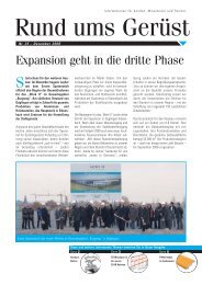
<strong>Layher</strong>®<br />
More Possibilities. The Scaffolding System.<br />
<strong>Layher</strong> <strong>Uni</strong><strong>Compact</strong>Tower<br />
Mobile access and working towers<br />
in accordance with: HD 1004;<br />
DIN 4422, Part 1 (Version 8/92)<br />
Working platform 1.5 x 1.8 m<br />
Max. working height:<br />
in closed rooms 10.6 m, outdoors 9.6 m<br />
Permissible load 2 kN/m2 on max. one working level:<br />
scaffold group 3 acc. to HD 1004;<br />
DIN 4422, Part 1 (Version 8/92)<br />
Aluminium Rolling Towers<br />
Instructions for Assembly and Use
2<br />
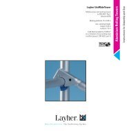
Tower models without ladder access <strong>Layher</strong> <strong>Uni</strong><strong>Compact</strong>Tower<br />
For outdoor use observe height limits!<br />
Tower models<br />
5001– 5004<br />
Tower model 5001 5002 5003 5004<br />
Working height (m) 3.4 4.4 5.4 6.4<br />
Tower height 1) (m) 2.6 (2.45) 3.6 (3.45) 4.6 (4.45) 5.6 (5.45)<br />
Platform height (m) 1.4 2.4 3.4 4.4<br />
Weight (kg) [without ballast] 96.8 144.5 156.7 178.6<br />
Tower models<br />
5005– 5008<br />
1) Values in brackets: minimum tower height incl. spigots.<br />
Tower model 5005 5006 5007 5008<br />
Working height (m) 7.4 8.6 9.6 10.6<br />
Scaffold height 1) (m) 6.6 (6.45) 7.79 (7.64) 8.79 (8.64) 9.79 (9.64)<br />
Platform height (m) 5.4 6.6 7.6 8.6<br />
Weight (kg) [without ballast] 238.0 339.0 363.2 379.1<br />
1) Values in brackets: minimum tower height incl. spigots.
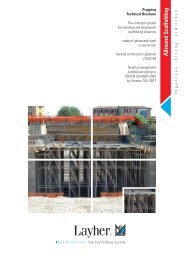
Assembly Sequence <strong>Layher</strong> <strong>Uni</strong><strong>Compact</strong>Tower<br />
�1 The general instructions for assembly and use given on page 8 must be followed. The examples of assembled tower models 5001– 5008 as shown (see page 2)<br />
are intended for use in rooms closed on all sides. In accordance with European HD 1001 amended January 1, 1987, the platform height outdoors must not<br />
exceed 8 m free standing. The material and ballasting tables on page 7 must be complied with.<br />
�2 Tower model<br />
5001<br />
�3 Assembly of bottom<br />
working platform<br />
�3.1 Tower models<br />
5002 – 5005<br />
�4 Assembly of bottom<br />
working platform<br />
�4.1 Tower models<br />
5006 – 5008<br />
�1<br />
�1<br />
�5<br />
�1<br />
�5<br />
�6<br />
�8<br />
�1<br />
�1<br />
�10<br />
�6<br />
�10<br />
�7<br />
�6<br />
�10<br />
�1<br />
�9<br />
→<br />
�9<br />
�7<br />
�1<br />
Access side<br />
�2<br />
�9<br />
�32<br />
�20<br />
�20<br />
�8<br />
�5<br />
�5<br />
�1<br />
�1<br />
�1<br />
�2<br />
1. In the case of tower 5001, insert the castors �1<br />
into the ladder frames �5 and secure them against<br />
dropping out by tightening the wing screws on the<br />
spindle nuts.<br />
2. Connect the two ladder frames �5 with two<br />
double guardrails �8 to brace them. Then suspend<br />
two decks �9 from the 4th rungs from the bottom<br />
of the ladder frames �5 .<br />
The snap-on claws of all parts must be attached to<br />
the ladder frames �5 from above. The horizontal<br />
distance between the decks must not exceed 25 mm.<br />
1. Insert the castors �1 into the ladder frames �5<br />
and secure them against dropping out by tightening<br />
the wing screws on the spindle nuts.<br />
2. A step bracket �32 is bolted to the centre of the<br />
ladder frames �5 and diagonal braces �7 are attached.<br />
Then the deck �9 and the access deck �10<br />
must be attached as shown in the general<br />
drawings (page 2).<br />
1. Insert the castors �1 into the mobile beams �2<br />
and secure them against dropping out by tightening<br />
the wing screws on the spindle nuts.<br />
2. Then clamp the base strut �20 to the tube of the<br />
mobile beam support �2 and attach the guardrail<br />
�6 to the mobile beam support �2 .<br />
3. The deck �9 and the access deck �10 or guardrails<br />
�6 must be attached as shown in the general<br />
drawings (page 2).<br />
3. A three-part side guard must be attached when<br />
this is required by the regulations applying for the<br />
job to be performed.<br />
To lift out the individual parts, the closing elements<br />
of the snap-on claws are pressed to open<br />
them. The red closing elements of the decks<br />
mean that one man can install and remove the<br />
decks effortlessly; first they must be released<br />
and the deck positioned on the rung with the<br />
elements opened, and then the elements on the<br />
opposite end are released and the deck lifted out.<br />
Use the threaded spindles for vertical alignment<br />
of the tower.<br />
The horizontal distance between the decks must<br />
not exceed 25 mm.<br />
The guardrails �6 and diagonal braces �7<br />
must be slid as far as possible outwards after<br />
being snapped in.<br />
Use the threaded spindles for vertical alignment<br />
of the tower.<br />
Further assembly for towers 5002 to 5004 as per<br />
section 6.<br />
The horizontal distance between the decks must not<br />
exceed 25 mm. The guardrails �6 and diagonal<br />
braces �7 must be slid as far as possible outwards<br />
after being snapped in (see drawings on<br />
page 2).<br />
Further assembly for towers 5006 to 5008 as per<br />
section 5.<br />
3
4<br />
Assembly Sequence <strong>Layher</strong> <strong>Uni</strong><strong>Compact</strong>Tower<br />
�5 Assembly of intermediate<br />
platforms<br />
Tower models<br />
5005 –5008<br />
�6 Assembly of top platform<br />
Tower models<br />
5002 – 5008<br />
�11<br />
�11<br />
�13<br />
�11<br />
�7 Adjustment<br />
of mobile beams<br />
�5<br />
�5<br />
�1<br />
�2<br />
�11<br />
�11<br />
�7<br />
�8<br />
�10<br />
�6<br />
�12<br />
�9<br />
�6<br />
�10<br />
�9<br />
K<br />
�7<br />
�6<br />
→ →<br />
M<br />
�5<br />
V<br />
S<br />
�8<br />
→ →<br />
�5<br />
�11<br />
�11<br />
�5<br />
�12<br />
�13<br />
�11<br />
During erecting and dismantling, system decks<br />
or scaffolding planks according to DIN 4420<br />
(minimum dimensions 28 x 4.5 x 250 cm long)<br />
must be installed as auxiliary decks at heights<br />
of max. 2.0 m. These auxiliary decks provide<br />
firm footing for erecting and dismantling and<br />
must be removed after assembly is complete.<br />
The full deck area must be boarded over.<br />
1. Further assembly is achieved by the attachment<br />
of ladder frames �5 and bracing using two diagonal<br />
braces �7 and guard rails �6 in accordance<br />
with the general drawings (see p. 2). The joints of<br />
the ladder frames �5 must be secured with spring<br />
clips �11 .<br />
2. With a height distance of max. 4.0 m, intermediate<br />
platforms each comprising one deck �9 and<br />
one access deck �10 must be installed. If these<br />
platforms are used only as intermediate platforms<br />
for ascent, it is sufficient to provide two guardrails<br />
�6 per side as side guards. If the platforms are<br />
used for working, two guardrails per side and toe<br />
boards (see section 5) must be installed. The top<br />
�11<br />
�13<br />
�5a<br />
�10<br />
�6<br />
�6<br />
�12 �6<br />
�6<br />
�9<br />
�5<br />
�12<br />
The mobile beam �2 permits work up against the<br />
wall. It can be moved in and out in the assembled<br />
state. Care must be taken that before assembly<br />
the ballast weights given in the ballasting table<br />
are fitted at the correct place (see p. 7).<br />
For adjustment in the assembled state, the middle<br />
support (M) provided on the mobile beam �2 is<br />
lowered as far as possible and secured.<br />
The load on the castors �1 is reduced at the<br />
�5a<br />
�5<br />
�11<br />
�13<br />
or other working level must then not be used. The<br />
toe boards must be removed there.<br />
The guardrails �6 and diagonal braces �7<br />
must be pushed outward as far as possible<br />
after installation.<br />
The horizontal spacing between the decks must<br />
not exceed 25 mm.<br />
3. When assembling the towers, care must always<br />
be taken that the diagonal braces �7 , decks �9 ,<br />
�10 and guardrails �6 are installed in the correct<br />
arrangement (see general drawings, p. 2). Here<br />
the next highest ladder frames �5 may not be<br />
attached until the ladder frames �5 beneath them<br />
have been braced accordingly.<br />
4. During dismantling the respective diagonal<br />
braces �7 and bracing elements �6 , �7 may<br />
not be removed until the ladder frames �5<br />
above them have been removed.<br />
For further assembly see section 6.<br />
After attaching the top ladder frames �5 or �5a and<br />
securing them with spring clips �11 an access deck<br />
�10 and deck �9 are suspended from the 5th rung<br />
from the top. The regulation side guard is provided<br />
by installing two double guardrails �8 or four single<br />
guardrails �6 . Place two toe boards �12 between<br />
the ladder frames �5 and secure them by inserting<br />
two 1.44 m end toe boards �13 .<br />
The diagonal braces �7 and guardrails �6 ,�8<br />
must be pushed outward as far as possible<br />
after installation! The horizontal spacing between<br />
the decks must not exceed 25 mm.<br />
sliding parts by turning the spindle (S) until the<br />
adjustment part (V) can be adjusted after loosening<br />
of the clamping wedge (K). After adjustment,<br />
the clamping wedge (K) must be fixed again, the<br />
load returned to the castor by turning the spindle<br />
back, and the middle support (M) moved up and<br />
secured.
Assembly Sequence <strong>Layher</strong> <strong>Uni</strong><strong>Compact</strong>Tower<br />
�8 Operating the castors<br />
Dismantling Sequence<br />
Wall support<br />
Wall support under load<br />
Rolling tower decks �9 �10<br />
Fix<br />
wing screw<br />
�1<br />
�2<br />
�5<br />
During assembly and working, the castors �1 can<br />
be fixed by pressing down the brake lever identified<br />
as Stop. In the braked condition the lever<br />
identified as Stop must be down.<br />
For movement, release the castors �1 by pressing<br />
the other lever.<br />
During erecting and dismantling, system decks or scaffolding planks according to DIN 4420 (minimum dimensions 28 x 4.5 x 250 cm long) must be installed<br />
as auxiliary decks at heights of max. 2.0 m. These auxiliary decks provide firm footing for erecting and dismantling and must be removed after assembly<br />
is complete. The full deck area must be boarded over.<br />
Plan view<br />
�27<br />
�26<br />
�27<br />
Maximum height adjustment (spindle travel)<br />
without deck at the base plate = 15 cm<br />
Dismantling is carried out in the reverse order of<br />
assembly.<br />
Do not remove the respective bracing elements<br />
such as diagonal braces �2 , guardrails �6 or<br />
access decks �10 until the ladder frames �5 ,<br />
Rolling tower decks �9 �10<br />
→<br />
Stop<br />
�27<br />
�26<br />
�27<br />
�3<br />
Plan view,<br />
with mobile beam<br />
�27<br />
�26<br />
�14<br />
�5 �5a<br />
�27<br />
�26<br />
�27<br />
�27<br />
�2 �2<br />
�5a above them have been removed.<br />
To lift out the various parts, press the locking clips<br />
of the snap-on claws to open them. The red<br />
locking clips of the decks permit effortless removal<br />
and insertion by one person; they must first be<br />
Side view<br />
�27<br />
�5 �5a<br />
�26<br />
�27<br />
released and the deck with its opened clip placed<br />
on the rung, then the clips at the opposite end are<br />
opened and the deck is lifted out.<br />
For work performed on a load-bearing wall, ballasting<br />
can be reduced in accordance with the ballasting<br />
table (see p. 7).<br />
In this case, wall supports must be installed on<br />
both sides of the tower. To do so, the <strong>Uni</strong> distance<br />
tube �26 is used and attached with couplers �27 to<br />
the ladder frames �5 , �5a . The mobile beams must<br />
be installed so that they project from the side<br />
facing away from the wall. The wall supports<br />
must be attached at the height of the top working<br />
platform or at most 1 m below that.<br />
5
�3 Base tube 1211.180<br />
1.8 m<br />
�5 Ladder frame 150/8 1299.008<br />
�5a Ladder frame 150/4 1299.004<br />
�6 Guardrail 1205.180<br />
1.8 m<br />
�7 Diagonal brace 1208.180<br />
2.5 m<br />
�8 Double guardrail 1206.180<br />
1.8 m<br />
6<br />
Components <strong>Layher</strong> <strong>Uni</strong><strong>Compact</strong>Tower<br />
�1 Castor 200<br />
with spindle 7 kN and locking screw 1259.200<br />
�2 Mobile beam with clip 1323.320<br />
3.2 m<br />
lockable<br />
�9 Deck 1241.180<br />
1.8 m<br />
�10 Access deck 1242.180<br />
1.8 m<br />
�11 Spring clip<br />
1250.000<br />
�12 Toe board with claw 1239.180<br />
1.8 m<br />
�13 End toe board 1238.144<br />
1.44 m<br />
�21 Deck support, bolt-on 1326.090<br />
0.9 m<br />
�25 Ballast 1249.000<br />
10 kg<br />
�26 <strong>Uni</strong> distance tube 1275.180<br />
1.8 m<br />
�27 Special screw coupler,<br />
rigid<br />
19 mm WS 1269.019<br />
22 mm WS 1269.022<br />
�32 Step bracket 1344.003<br />
0.9 m
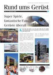
Parts List <strong>Layher</strong> <strong>Uni</strong><strong>Compact</strong>Tower<br />
�1 Table 1<br />
Ballasting<br />
Tower model without ladders Article No. 5001 5002 5003 5004 5005 5006 5007 5008<br />
Ladder frame 150/4 1299.004 – 2 – 2 – 2 – 2<br />
Ladder frame 150/8 1299.008 2 2 4 4 6 6 8 8<br />
Deck 1.8 m 1241.180 2 1 1 1 2 2 2 2<br />
Access deck 1.8 m 1242.180 – 1 1 1 2 2 2 2<br />
Guardrail 1.8 m 1205.180 – 6 2 6 8 9 9 11<br />
Diagonal brace 2.5 m 1208.180 – 2 2 4 4 6 6 8<br />
Double guardrail 1206.180 2 – 2 – 2 – 2 –<br />
Step bracket 1344.003 – 1 1 1 1 – – –<br />
Mobile beam with clip, adjustable 1323.320 – – – – – 2 2 2<br />
Base strut 1.8 m 1324.180 – – – – – 1 1 1<br />
Toe board 1.8 m, with claw 1239.180 – 2 2 2 2 2 2 2<br />
End toe board 1.44 m 1238.144 – 2 2 2 2 2 2 2<br />
Spring clip 1250.000 – 4 4 8 8 16 16 20<br />
Castor 200 w. spindle, 7 kN 1259.200 4 4 4 4 4 4 4 4<br />
Ballast 1249.000 For the number of ballast weights see Ballasting table, see p. 7.<br />
For ballasting use <strong>Layher</strong> ballasting weights �25 , Art. No. 1249.000 (10 kg each). Simple, fast and secure fixing of the appropriate ballast at the right places is<br />
achieved using the coupler with star handle. Only these ballast weights may be used, and not liquid or granular ballast materials. The ballast weight must be<br />
distributed evenly over all fixing points for the ballast. Any remainder not divisible by 4 must be distributed over the 'A' fixing points.<br />
Tower model 5001 5002 5003 5004 5005 5006 5007 5008<br />
Use indoors central position* � � 4 8 8 � 4 6<br />
off-centre position – – – – – � 4 8<br />
Use outdoors central position* � � 6 14 20 24 36 ✕<br />
off-centre position – – – – – 24 36 ✕<br />
off-centre position with wall support – – – – – 24 36 ✕<br />
*Assembly with adjustable mobile beam �2 ,<br />
which must be fully extended.<br />
Assembly without console brackets: attachment of ballast weights (plan view)<br />
Assembly without mobile beam central position off-centre position<br />
(plan view)<br />
A<br />
Ladder frame �5<br />
Mobile �2<br />
beam<br />
A<br />
Base strut �20<br />
Base strut �20<br />
Deck �9 �10<br />
� = Fixing points for ballast<br />
A = Fixing points for ballast weight remainder not divisible by 4<br />
A<br />
Table denotes the number of ballast weights, 10 kg each. � = no ballast needed ✕ = not permitted<br />
A<br />
Mobile �2<br />
beam<br />
7
General Instructions for Assembly and Use<br />
<strong>Layher</strong> <strong>Uni</strong><strong>Compact</strong>Tower<br />
The rolling tower may be used for the scaffolding group<br />
and as additionally specified in the German operating<br />
safety regulations (BetrSichV). The rules of the German<br />
professional associations governing the building of rolling<br />
towers (BGR 172/April 2000) and of small scaffolding<br />
units (BGR 173/April 2000) must be complied with.<br />
For mobile working platforms (rolling towers), DIN 4422<br />
Part 1 (issue 8/92) applies. For small scaffolding units<br />
(platform height ≤ 2 m), BGR 173 applies.<br />
The user of mobile working platforms must<br />
comply with the following instructions:<br />
1. The user must check the suitability of the selected<br />
rolling tower for the work to be performed (Section 4<br />
of BetrSichV).<br />
2. The max. platform height is, in accordance with<br />
DIN 4422 Part 1:<br />
– inside buildings 12.0 m<br />
– outside buildings 8.0 m<br />
The material and ballasting requirements on page 7<br />
must be complied with; risk of accidents in the event<br />
of non-compliance. For greater heights, additional<br />
measures are necessary, obtainable from the manufacturer.<br />
Stability of the rolling tower must be assured.<br />
3. The assembly, modification or dismantling of the<br />
rolling tower in accordance with the present instructions<br />
for assembly and use may only be performed<br />
under the supervision of a qualified person and by<br />
professionally suitable personnel after special<br />
instruction. Only the scaffolding types shown in these<br />
instructions for assembly and use may be used.<br />
The unit must, after assembly and before being put into<br />
service, be inspected by persons qualified to do so<br />
(Section 10 of BetrSichV). The inspection must be documented<br />
(Section 11 of BetrSichV). During assembly,<br />
modification or dismantling, the rolling tower must be<br />
provided with a prohibition sign indicating “No access<br />
allowed” and be adequately safeguarded by means of<br />
barriers preventing access to the danger zone<br />
(BetrSichV Annex 2, para. 5.2.5).<br />
4. Before assembly, examine all components to ensure<br />
they are in perfect condition. Only undamaged original<br />
components for <strong>Layher</strong> mobile working platform<br />
systems may be used. Clean dirt off tower parts such<br />
as snap-on claws and spigots after use. Secure tower<br />
components against slipping and impacts during truck<br />
transportation. Ensure that the tower parts are stored<br />
where they are free from weather effects. Handle<br />
tower parts in such a way that they are not damaged.<br />
For attachment of the ballast weights and wall supports<br />
see p. 7 of these instructions for assembly and use.<br />
5. During erecting and dismantling, install system<br />
decks or scaffolding planks according to DIN 4420<br />
(minimum dimensions 28 x 4.5 x 250 cm long) as<br />
auxiliary decks at heights of max. 2.0 m. These<br />
auxiliary decks provide firm footing for erecting<br />
and dismantling and must be removed after<br />
assembly is complete. The full deck area must be<br />
boarded over.<br />
8107.233 Edition: 1-01-04.1<br />
With a distance of 4.0 m, the system requires that<br />
inter-mediate platforms with access openings must be<br />
installed. For safety reasons, it is advisable for two<br />
persons to erect the towers above a height of 4.0 m. To<br />
assemble the upper tower sections the individual parts<br />
must be hoisted using transportation ropes.<br />
Small quantities of tools and materials can be carried<br />
up in person, otherwise also hoisted by transportation<br />
ropes to the working level.<br />
6. Use spring clips to secure the ladder frame joints<br />
against inadvertent lift-off.<br />
7. The guardrails and diagonal braces must be slid<br />
as far as possible outwards after being snapped in.<br />
8. For intermediate platforms used only for ascent, it is<br />
sufficient to provide two guardrails. For small towers<br />
where the height of the deck exceeds 1.0 m, equipment<br />
must be provided that permits the attachment of side<br />
guards in accordance with DIN 4420-1.<br />
9. Access to the working platform is only permitted on<br />
the inside of the tower (except for model 5001).<br />
10. It is not permitted to work on two or more platforms<br />
at the same time. Please consult the manufacturer if<br />
exceptions to the rule are required.<br />
11. Persons working on mobile working platforms must<br />
not lean against the guardrails.<br />
12. Lifting gear must not be attached to or used on mobile<br />
working platforms.<br />
13. The tower may only be erected and moved on level<br />
and sufficiently firm ground and only longitudinally or<br />
diagonally. Any impacts must be avoided. When the base<br />
is widened on one side and is fitted with wall supports,<br />
only movement parallel to the wall is permissible. Normal<br />
walking speed must not be exceeded during movement.<br />
14. No personnel or unsecured objects may be on the<br />
tower during movement.<br />
15. After movement, lock the castors by pressing down<br />
the brake lever.<br />
16. The towers must not be subjected to any aggressive<br />
fluids or gases.<br />
17. Mobile working platforms must not be bridged<br />
together unless a special structural analysis is<br />
available. The same applies for all other special structures,<br />
for example suspended scaffolding and the like.<br />
18. For outdoor use or in open buildings, the mobile<br />
working platform must be moved to a spot protected<br />
from wind at wind speeds above 6 on the Beaufort<br />
scale or at the end of a shift, or other measures must<br />
be taken to secure it against toppling over (Wind speeds<br />
above 6 can be recognised by noticeable difficulty when<br />
walking.) If possible, rolling towers used on the outside<br />
of buildings must be securely attached to the building<br />
or to another structure. It is recommended that rolling<br />
towers be anchored when they are left unattended.<br />
19. Decks can be raised or lowered by a rung to achieve<br />
a different working height. Care must be taken here to<br />
ensure that the specified rail heights of 1.0 m are<br />
complied with. The diagonal braces are also raised or<br />
lowered by the corresponding distance. If this construction<br />
form is selected, please consult the manufacturer<br />
on whether an additional proof of stability is required.<br />
20. The tower must be set vertically with the adjusting<br />
spindles. The maximum inclination must not exceed 1%.<br />
21. Sliding in of the mobile beam is only permissible<br />
with due consideration of the Instructions for<br />
Assembly and Use and of the ballasting requirements,<br />
see p. 7.<br />
22. The access hatches must be kept closed except<br />
when in use.<br />
23. All couplers must be tightened with 50 Nm.<br />
24. A mobile working platform is not intended for use<br />
as a stairway tower providing access to other structures.<br />
25. It is prohibited to jump on the decks.<br />
26. A check must be made that all parts, auxiliary tools<br />
and safety equipment (ropes etc.) for erecting the mobile<br />
working platforms are available on the site.<br />
27. Avoid horizontal and vertical loads that can cause<br />
the mobile work platform to topple over, such as<br />
- horizontal loads, for example when working on<br />
adjacent structures<br />
- additional wind loads (due to tunnel effect from<br />
through-type buildings, unclad buildings and corners).<br />
28. When stipulated, mobile beams or outriggers and<br />
ballast must be installed.<br />
29. It is prohibited to increase the height of the decking<br />
by using ladders, boxes or other objects.<br />
30. It is not permitted to construct bridges between the<br />
rolling tower and a building.<br />
31. Rolling towers are not designed to be lifted or<br />
suspended.<br />
All dimensions and weights are for guidance only.<br />
Subject to technical modifications.<br />
Sales exclusively on the basis of our currently<br />
valid general terms of business.<br />
Wilhelm <strong>Layher</strong> GmbH & Co. KG<br />
Scaffolding Grandstands Ladders<br />
<strong>Layher</strong>®<br />
More Possibilities. The Scaffolding System.<br />
Post Box 40<br />
D-74361 Güglingen-Eibensbach<br />
Phone: **49-71 35-7 00<br />
Fax: **49-7135-703 72<br />
E-mail: export@layher.com<br />
http://www.layher.com