Pipe Joints, Couplings & Repair Clamps - ECO
Pipe Joints, Couplings & Repair Clamps - ECO
Pipe Joints, Couplings & Repair Clamps - ECO

Create successful ePaper yourself
Turn your PDF publications into a flip-book with our unique Google optimized e-Paper software.
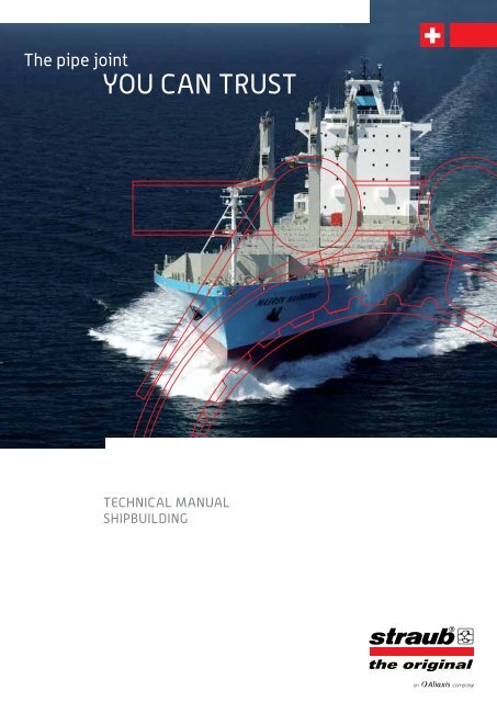
The pipe joint<br />
YOU CAN TRUST<br />
TeChNiCAL MANUAL<br />
ShiPBUiLDiNG
The TeChNiCAL MANUAL fOR ShiPBUiLDiNG.<br />
The name STRAUB is synonymous with Swiss quality, expertise and reliability. As a company operating worldwide<br />
and specialising in the field of pipe connections, STRAUB is as renowned for having developed the ‘original’ pipecoupling<br />
of its type. With 40-years experience and the consistent high standards STRAUB continues to develop new<br />
products and innovative pipe work solutions.<br />
The idea of connecting standard pipes with a flexible joining system without having to work on pipe ends was<br />
the brainchild of the company’s founder, Immanuel Straub, who, on a visit to a shipyard in Northern Germany in<br />
the 60’s realised the potential of introducing a flexible system that did not require work to be undertaken on pipe<br />
ends. Durability, compactness, size and weights of maritime products were becoming all the more important in the<br />
building of new ships and this in turn influenced Immanuel Straub’s pipe connecting concept and led the way to a<br />
new era of maritime pipe construction.<br />
The trademarked STRAUB-METAL-GRIP coupling has been developed and successfully launched into the maritime<br />
market. Working in conjunction with German shipbuilders and Germanischer Lloyd, the use and application of these<br />
flexible, removable and reusable couplings have been thoroughly tested and fully approved.<br />
The German and French Navy were quick to recognise the many benefits of the STRAUB-METAL-GRIP. Being light,<br />
space-saving, efficient and quick to install, this innovative coupling system has to been installed in their frigates,<br />
submarines and aircraft carriers.<br />
Navy shock tests have shown that STRAUB couplings remain sealed even in a distressed condition (i.e. following<br />
a ship collision or an underwater explosion). This is due to their low weight and is in complete accordance with<br />
the principle and classification “Safe to the next Port”. Beyond the shipbuilding arena, this coupling is also used<br />
successfully in a broad variety of applications such as water, gas, industry, building construction and civil engineering.<br />
The STRAUB brand has become an industry standard worldwide and has become synonymous with excellence and<br />
the principle of efficiently joining pipes. To this day, STRAUB maintains its traditional high-safety margin for end-user<br />
peace of mind.<br />
OUR qUALiTY PRODUCTS – YOUR ADDeD vALUe.<br />
The ISO-9001-QA certificate was originally attained in 1995 and successful<br />
recertification achieved in 1999, 2003 and 2008 thus providing official<br />
verification of STRAUB quality. We are currently the sole supplier of all approvals<br />
and classes. In 2008, Straub Werke AG was also ISO-14001 certified.<br />
2
3<br />
CONTeNTS<br />
The principle 4<br />
Flexibility 4<br />
A basic concept 5<br />
Advantages for shipbuilding 6<br />
STrAUB prODUcTS 8<br />
STRAUB FIRE PROTECTION SYSTEM 9<br />
STRAUB-GRIP-L 10<br />
STRAUB-GRIP-L datasheets 11<br />
STRAUB-GRIP-L FIRE-FENCE<br />
datasheets 13<br />
STRAUB-METAL-GRIP 15<br />
STRAUB-METAL-GRIP datasheets 16<br />
STRAUB-METAL-GRIP FIRE-FENCE<br />
datasheets 18<br />
STRAUB-FLEX 20<br />
Datasheet 21<br />
STRAUB REPAIR CONCEPT 22<br />
STRAUB-OPEN-FLEX 23<br />
Datasheet 23<br />
STRAUB-CLAMP 24<br />
Datasheet 24<br />
ACCESSORIES 25<br />
TechnicAl inFOrMATiOn 26<br />
ApprOvAlS 34<br />
reFerenceS 38
fLexiBiLiTY -<br />
The PeRfeCT PROPeRTY iN ShiPBUiLDiNG<br />
It is generally known that the sea swell can cause significant deformation of the hull and pressure surges in system<br />
pipelines whilst the ship is at sea. This leads to a constant strain on the piping systems. Rigid pipe connections<br />
such as flanges or welded collars transfer strains directly to other components in the form of stress. Compensators<br />
therefore become necessary.<br />
The Original STRAUB pipe coupling combines connection and compensator all in one. The STRAUB design offers<br />
pipe flexibility that dissipates stress and increases the component service life. The coupling’s rubber sealing<br />
gasket efficiently dampens vibrations and noise. Fatigue failures are reduced, system reliability is increased and<br />
passenger comfort is much better. These special properties of STRAUB-GRIP and STRAUB-FLEX couplings represent<br />
a decisive added benefit for ship owners and operators.<br />
Flexibility in the sealing system<br />
(GRIP and FLEX couplings)<br />
Flexibility in the anchoring system<br />
(GRIP couplings)<br />
4
5<br />
STRAUB-GRIP<br />
“Pull-out” resistant<br />
eiGhT PRODUCTS:<br />
STRAUB-fiRe-feNCe<br />
“fireproof”<br />
STRAUB-CLAMP<br />
“for emergencies”<br />
A BASiC CONCePT<br />
TwO DeSiGN veRSiONS:<br />
STRAUB-GRiP-L<br />
“economical”<br />
STRAUB-PLAST-GRiP<br />
“the plastics solution”<br />
STRAUB-MeTAL-GRiP<br />
“strong”<br />
STRAUB-COMBi-GRiP<br />
“the transition joint”<br />
STRAUB-FLEX<br />
Axially flexible<br />
STRAUB-fLex<br />
“flexible”<br />
STRAUB-OPeN-fLex<br />
“universal wrap-around joint”
Advantages for<br />
ShIPBUILdING<br />
ThE SPECIAL PROPERTIES OF STRAUB<br />
USER BENEFITS wITh STRAUB<br />
fast and<br />
economical<br />
Truly PROGRESSIvE SEALING EFFECT<br />
(Lip with pressure equalisation channel)<br />
Increasing internal pressure increases the<br />
contact pressure of the sealing lip.<br />
PROGRESSIvE ANChORING EFFECT<br />
Increasing axial pressure leads to the teeth being<br />
pressed into the pipe surface.<br />
Space-saving<br />
• Requires low storage space<br />
• Good accessibility<br />
• Locking part can be rotated into the optimum fitting position –<br />
access only necessary from one side<br />
• Close pipe arrangement possible, providing space for other<br />
components<br />
• Little space required for later installation<br />
• Installation without special tools<br />
• No work required on the pipe ends<br />
• Removable and reusable<br />
• Short installation time and minimum downtime<br />
• High assembly tolerances<br />
6
7<br />
Multi-Purpose<br />
• Connects the broadest variety of pipe materials; ideal also for CuNiFe<br />
• Connects different diameters<br />
• Can be used for pressure, drainage and suction pipes<br />
Safe<br />
• No risk of fire or explosion during installation<br />
• No costs for safety measures<br />
• Quadruple safety factor<br />
• STRAUB has all IACS approvals<br />
• Flexible design absorbs overstressing<br />
Damping<br />
• Plenty of rubber to absorb vibrations/oscillations<br />
• Reduces pressure blows<br />
• Reduces fatigue failures<br />
• Noise reduction increases passenger comfort<br />
Tension-free<br />
• Increases the life of fittings and systems<br />
• Compensates for axial displacement and misalignment<br />
• Coupling and compensator in one<br />
Long life<br />
• Corrosion resistant<br />
• Good resistance to heat and chemicals<br />
• Low torque guarantees long life<br />
Light<br />
• Light weight<br />
• Low transport costs<br />
• Increases the payload<br />
PN16; Ø 114,3 mm<br />
STRAUB connection 2,1 kg Flanged connection 8,6 kg
STRAUB PROdUCTS<br />
8
9<br />
ThE STRAUB FIRE PROTECTION SYSTEM<br />
STRAUB-fiRe-feNCe - fOR APPLiCATiONS wheRe fiRe<br />
PROTeCTiON iS A ReqUiReMeNT.<br />
The fireproof coupling is a STRAUB-METAL-GRIP or a STRAUB-GRIP-L with a fireprotection<br />
cover. In the event of fire, the intumescent fire protection coating expands,<br />
protectively enclosing the coupling. During this process, the coupling retains its full<br />
operational capability – without any limitations whatsoever.<br />
Despite the fire protection, the STRAUB-FIRE-FENCE can be installed in a spacesaving<br />
manner. It has a high level of crush resistance, and thanks to the patented<br />
design is still remarkably light weight. The STRAUB-FIRE-FENCE is an impressive<br />
and innovative design yet has all the trademarks and properties of traditional classic<br />
STRAUB couplings.<br />
We are extremely proud of the fact that our FIRE-FENCE coupling has achieved<br />
worldwide certification by all IACS members according to IACS URP 2 and ISO 19921.<br />
Operating pressure: as STRAUB-METAL-GRIP and STRAUB-GRIP-L<br />
Range of diameters:<br />
STRAUB-METAL-GRIP-FIRE-FENCE 30.0 to 406.4 mm<br />
STRAUB-GRIP-L-FIRE-FENCE 26.9 to 406.4 mm<br />
Temperature range: -20˚ C to +100˚ C<br />
Order example:<br />
STRAUB-METAL-GRIP-FIRE-FENCE 76.1, EPDM, W4<br />
The MOBiLe fiRe PROTeCTiON COveR<br />
STRAUB couplings that have already been installed can be quickly and easily upgraded<br />
to the STRAUB-FIRE-FENCE version using the mobile fire protection cover.<br />
Available for models STRAUB-GRIP-L, STRAUB-METAL-GRIP and STRAUB-FLEX.
STRAUB-GRIP-L<br />
The SAfe AND LiGhT weiGhT PiPe CONNeCTiON<br />
“Pull-out” resistant pipe connections made from all stainless steel. The<br />
STRAUB-GRIP-L is the light range from STRAUB. It is suitable for all<br />
applications in shipbuilding and offshore industries. The particular ad-<br />
vantages to the STRAUB-GRIP-L are its low weight and its single-bolt<br />
system for the small-diameter couplings.<br />
• For all marine pipe systems, essential and non essential, IACS tested<br />
• Also reliably joins CuNiFe, duplex or titanium pipe materials<br />
• Absorbs stresses in the pipe system and during operation<br />
• Minimal bolt torque to optimise lifespan of seal<br />
• Simple and fast assembly, thus reduce installation time<br />
• Separate independent anchoring and sealing mechanisms<br />
Operating pressure in shipbuilding: 16 bar<br />
Diameters: 26.9 to 609.6 mm<br />
Temperature range: -20° C to 100° C<br />
Order example: STRAUB-GRIP-L 76.1, EPDM, W5<br />
10
11<br />
STRAUB-GRIP-L Ø 26.9 - 219.1 mm<br />
Components / Materials W1 W2 W4 W5<br />
Casing 1.4404 / 1.4571 (V4A)<br />
Bolts 1.4404 / 1.4435 (V4A)<br />
U-Bars 1.4571 (V4A)<br />
Anchoring ring 1.4310<br />
Strip insert (option) 1.4435 (V4A) / HDPE / PVDF<br />
Sealing sleeve<br />
Temp.: -20°C up to +100°C<br />
EPDM<br />
Medium: all qualities of water, waste water, air, solids and chemical products<br />
Sealing sleeve<br />
Temp.: -20°C up to +100°C<br />
NBR<br />
Medium: water, gas, oil, fuel and other hydrocarbons<br />
Sealing sleeve<br />
Temp.: -20°C up to +180°C<br />
VITON A (FKM, FPM) Medium: ozone, oxygen, acids, gas, oil and fuel (only with strip insert)<br />
other rubber qualities on request (HNBR, ...)<br />
OD<br />
[mm]<br />
Clamping range<br />
[mm]<br />
PN<br />
[bar]<br />
B<br />
[mm]<br />
C<br />
[mm]<br />
DV<br />
[mm]<br />
KV<br />
[mm]<br />
R without<br />
strip insert<br />
[mm]<br />
R with<br />
strip insert<br />
[mm]<br />
torque<br />
rate<br />
[Nm]<br />
allen<br />
head<br />
[mm]<br />
26.9 26.4 - 27.4 16 46 19 43 70 5 5 5 5 6 0.2<br />
30.0 29.5 - 30.5 16 46 17 47 75 5 5 5 5 6 0.2<br />
33.7 33.2 - 34.2 16 46 17 51 75 5 5 5 5 6 0.2<br />
38.0 37.5 - 38.5 16 61 25 57 90 5 5-10 7.5 6 8 0.3<br />
42.4 41.9 - 42.9 16 61 25 62 95 5 5-10 7.5 6 8 0.4<br />
44.5 44.0 - 45.0 16 61 25 64 95 5 5-10 7.5 6 8 0.4<br />
48.3 47.8 - 48.8 16 61 25 67 100 5 5-10 7.5 6 8 0.4<br />
54.0 53.5 - 54.5 16 76 37 76 105 5-10 5-15 7.5 6 8 0.5<br />
57.0 56.4 - 57.6 16 76 37 76 105 5-10 5-15 10 6 8 0.5<br />
60.3 59.7 - 60.9 16 76 37 79 110 5-10 5-15 7.5 6 8 0.5<br />
66.6 64.9 - 67.3 16 95 35 87 126 5-10 5-20 10 6 8 1.1<br />
70.0 68.9 - 70.7 16 95 36 92 131 5-10 5-20 10 6 8 1.1<br />
73.0 72.3 - 73.7 16 95 41 96 142 5-10 5-25 12 6 8 1.1<br />
76.1 75.3 - 76.9 16 95 41 98 142 5-10 5-25 12 6 8 1.1<br />
79.5 78.7 - 80.3 16 95 35 100 142 5-10 5-25 12 6 8 1.1<br />
84.0 83.2 - 84.8 16 95 35 112 152 5-10 5-25 12 6 8 1.2<br />
88.9 88.0 - 89.8 16 95 41 111 157 5-10 5-25 12 6 8 1.2<br />
100.6 99.6 - 101.6 16 95 35 129 172 5-10 5-25 12 6 8 1.4<br />
101.6 100.6 - 102.6 16 95 35 130 172 5-10 5-25 15 6 8 1.4<br />
104.0 103.0 - 105.0 16 95 35 132 172 5-10 5-25 12 6 8 1.5<br />
104.8 103.8 - 105.8 16 95 35 133 172 5-10 5-25 12 6 8 1.5<br />
108.0 106.9 - 109.1 16 95 41 130 172 5-10 5-25 12 6 8 1.4<br />
114.3 113.2 - 115.4 16 95 41 136 177 5-10 5-25 12 6 8 1.4<br />
127.0 125.7 - 128.3 16 110 54 151 195 5-10 5-30 40 8 10 2.3<br />
129.0 127.7 - 130.3 16 110 54 153 195 5-10 5-30 40 8 10 2.4<br />
130.2 128.9 - 131.5 16 110 54 154 200 5-10 5-30 40 8 10 2.4<br />
133.0 131.7 - 134.3 16 110 54 157 200 5-10 5-30 40 8 10 2.5<br />
139.7 138.3 - 141.1 16 110 54 164 210 5-10 5-30 40 8 10 2.6<br />
141.3 139.9 - 142.7 16 110 54 166 210 5-10 5-30 40 8 10 2.6<br />
154.0 152.5 - 155.5 13 110 48 184 225 5-10 5-30 40 8 10 3.0<br />
159.0 157.4 - 160.6 13 110 54 183 225 5-10 5-30 40 8 10 2.8<br />
168.3 166.6 - 170.0 13 110 54 192 230 5-10 5-30 40 8 10 2.9<br />
219.1 216.9 - 221.3 10 142 80 250 295 5-10 5-30 60 10 12 5.9<br />
further sizes on request<br />
Remarks:<br />
W OD 26.9 – 60.3mm with one screw<br />
W Follow fitting / disassembly instructions<br />
W Strip inserts see page 25<br />
W Minimum wall thickness see page 28<br />
W manufactured according to DIN 86128, approved according to IACS 2007<br />
thread<br />
M...<br />
weight<br />
[kg]
STRAUB-GRIP-L Ø 180.0 - 406.4 mm<br />
Components / Materials W1 W2 W4 W5<br />
Casing 1.4404 / 1.4571 (V4A) 1.4404 / 1.4571 (V4A)<br />
Bolts 1.7220 1.4404 / 1.4435 (V4A)<br />
U-Bars 1.0737, galvanised 1.4404 / 1.4435 (V4A)<br />
Anchoring ring 1.4310 1.4310<br />
Strip insert (option) 1.4435 (V4A) / HDPE 1.4435 (V4A) / HDPE<br />
Sealing sleeve<br />
Temp.: -20°C up to +100°C<br />
EPDM<br />
Medium: all qualities of water, waste water, air, solids and chemical products<br />
Sealing sleeve<br />
Temp.: -20°C up to +100°C<br />
NBR<br />
Medium: water, gas, oil, fuel and other hydrocarbons<br />
Sealing sleeve<br />
Temp.: -20°C up to +180°C<br />
VITON A (FKM, FPM) Medium: ozone, oxygen, acids, gas, oil and fuel (only with strip insert)<br />
other rubber qualities on request (HNBR, ...)<br />
OD<br />
[mm]<br />
Clamping range<br />
[mm]<br />
PN<br />
[bar]<br />
B<br />
[mm]<br />
C<br />
[mm]<br />
DV<br />
[mm]<br />
KV<br />
[mm]<br />
R without<br />
strip insert<br />
[mm]<br />
R with<br />
strip insert<br />
[mm]<br />
torque<br />
rate<br />
[Nm]<br />
allen<br />
head<br />
[mm]<br />
180.0 178.0 - 182.0 10 141 80 205 255 5-10 5-35 50 10 12 5.9<br />
193.7 192.0 - 195.5 10 141 80 224 270 5-10 5-35 50 10 12 4.5<br />
200.0 198.0 - 202.0 10 141 80 230 275 5-10 5-35 50 10 12 4.7<br />
204.0 202.0 - 206.0 10 141 80 234 280 5-10 5-35 50 10 12 4.8<br />
244.5 242.0 - 247.0 5.5 141 80 275 320 5-10 5-35 50 10 12 4.8<br />
250.0 247.5 - 252.5 5.5 141 80 280 325 5-10 5-35 50 10 12 5.4<br />
254.0 251.5 - 256.5 5.5 141 80 284 325 5-10 5-35 50 10 12 5.5<br />
267.0 264.5 - 269.5 5 141 80 297 340 5-10 5-35 50 10 12 5.6<br />
273.0 270.5 - 275.5 4 141 80 303 345 5-10 5-35 60 10 12 5.7<br />
304.0 301.0 - 307.0 4 141 80 334 375 5-10 5-35 60 10 12 5.8<br />
323.9 320.5 - 327.0 3 141 80 354 395 5-10 5-35 60 10 12 6.2<br />
355.6 352.0 - 359.0 2.5 141 80 386 425 5-10 5-35 70 10 12 6.5<br />
406.4 402.5 - 410.5 2 141 80 436 470 5-10 5-35 70 10 12 6.5<br />
further sizes on request<br />
Remarks:<br />
W OD 26.9 – 60.3mm with one screw<br />
W Follow fitting / disassembly instructions<br />
W Strip inserts see page 25<br />
W Minimum wall thickness see page 28<br />
W manufactured according to DIN 86128, approved according to IACS 2007<br />
thread<br />
M...<br />
weight<br />
[kg]<br />
12
13<br />
STRAUB-GRIP-L-FIRE-FENCE Ø 26.9 - 219.1 mm<br />
Components / Materials W1 W2 W4 W5<br />
Casing 1.4404 / 1.4571 (V4A)<br />
Bolts 1.4404 / 1.4435 (V4A)<br />
U-Bars 1.4571 (V4A)<br />
Anchoring ring 1.4310<br />
Strip insert (option) 1.4435 (V4A) / HDPE / PVDF<br />
Sealing sleeve<br />
Temp.: -20°C up to +100°C<br />
EPDM<br />
Medium: all qualities of water, waste water, air, solids and chemical products<br />
Sealing sleeve<br />
Temp.: -20°C up to +100°C<br />
NBR<br />
Medium: water, gas, oil, fuel and other hydrocarbons<br />
Sealing sleeve<br />
Temp.: -20°C up to +180°C<br />
VITON A (FKM, FPM) Medium: ozone, oxygen, acids, gas, oil and fuel (only with strip insert)<br />
AD<br />
other rubber qualities on request (HNBR, ...)<br />
OD<br />
[mm]<br />
C<br />
R<br />
B<br />
Clamping range<br />
[mm]<br />
PN<br />
[bar]<br />
B<br />
[mm]<br />
KV<br />
DV<br />
C<br />
[mm]<br />
DV<br />
[mm]<br />
KV<br />
[mm]<br />
R without<br />
strip insert<br />
[mm]<br />
R with<br />
strip insert<br />
[mm]<br />
torque<br />
rate<br />
[Nm]<br />
allen<br />
head<br />
[mm]<br />
26.9 26.4 - 27.4 16 56 19 53 75 5 5 5 5 6 0.2<br />
30.0 29.5 - 30.5 16 56 17 57 80 5 5 5 5 6 0.2<br />
33.7 33.2 - 34.2 16 56 17 61 80 5 5 5 5 6 0.3<br />
38.0 37.5 - 38.5 16 71 25 67 95 5 5-10 7.5 6 8 0.5<br />
42.4 41.9 - 42.9 16 71 25 72 100 5 5-10 7.5 6 8 0.5<br />
44.5 44.0 - 45.0 16 71 25 74 100 5 5-10 7.5 6 8 0.5<br />
48.3 47.8 - 48.8 16 71 25 77 105 5 5-10 7.5 6 8 0.5<br />
54.0 53.5 - 54.5 16 86 37 86 110 5-10 5-15 7.5 6 8 0.5<br />
57.0 56.4 - 57.6 16 86 37 86 110 5-10 5-15 10 6 8 0.5<br />
60.3 59.7 - 60.9 16 86 37 89 115 5-10 5-15 7.5 6 8 0.7<br />
66.6 64.9 - 67.3 16 111 35 97 131 5-10 5-20 10 6 8 1.0<br />
70.0 68.9 - 70.7 16 111 36 102 136 5-10 5-20 10 6 8 1.2<br />
73.0 72.3 - 73.7 16 111 41 106 147 5-10 5-25 12 6 8 1.5<br />
76.1 75.3 - 76.9 16 111 41 108 147 5-10 5-25 12 6 8 1.4<br />
84.0 83.2 - 84.8 16 111 35 122 157 5-10 5-25 12 6 8 1.5<br />
88.9 88.0 - 89.8 16 111 41 121 162 5-10 5-25 12 6 8 1.5<br />
100.6 99.6 - 101.6 16 111 35 139 177 5-10 5-25 12 6 8 1.6<br />
101.6 100.6 - 102.6 16 111 35 140 177 5-10 5-25 15 6 8 1.6<br />
104.0 103.0 - 105.0 16 111 35 142 177 5-10 5-25 12 6 8 1.7<br />
104.8 103.8 - 105.8 16 111 35 143 177 5-10 5-25 12 6 8 1.7<br />
108.0 106.9 - 109.1 16 111 41 140 177 5-10 5-25 12 6 8 1.7<br />
114.3 113.2 - 115.4 16 111 41 146 182 5-10 5-25 12 6 8 1.8<br />
127.0 125.7 - 128.3 16 126 54 161 200 5-10 5-30 40 8 10 2.4<br />
129.0 127.7 - 130.3 16 126 54 163 200 5-10 5-30 40 8 10 2.5<br />
130.2 128.9 - 131.5 16 126 54 164 205 5-10 5-30 40 8 10 2.5<br />
133.0 131.7 - 134.3 16 126 54 167 205 5-10 5-30 40 8 10 2.6<br />
139.7 138.3 - 141.1 16 126 54 174 215 5-10 5-30 40 8 10 2.9<br />
141.3 139.9 - 142.7 16 126 54 176 215 5-10 5-30 40 8 10 3.0<br />
154.0 152.5 - 155.5 13 126 48 194 230 5-10 5-30 40 8 10 3.1<br />
159.0 157.4 - 160.6 13 126 54 193 230 5-10 5-30 40 8 10 3.2<br />
168.3 166.6 - 170.0 13 126 54 202 235 5-10 5-30 40 8 10 2.9<br />
219.1 216.9 - 221.3 10 158 80 260 300 5-10 5-30 60 10 12 6.9<br />
further sizes on request<br />
Remarks:<br />
W OD 26.9 – 60.3mm with one screw<br />
W Follow fitting / disassembly instructions<br />
W Strip inserts see page 25<br />
W Minimum wall thickness see page 28<br />
W manufactured according to DIN 86128, approved according to IACS 2007 and tested according to ISO 19921:2005E<br />
thread<br />
M...<br />
weight<br />
[kg]
STRAUB-GRIP-L-FIRE-FENCE Ø 180.0 - 406.4 mm<br />
Components / Materials W1 W2 W4 W5<br />
Casing 1.4404 / 1.4571 (V4A) 1.4404 / 1.4571 (V4A)<br />
Bolts 1.7220 1.4404 / 1.4435 (V4A)<br />
U-Bars 1.0737, verzinkt 1.4404 / 1.4435 (V4A)<br />
Anchoring ring 1.4310 1.4310<br />
Strip insert (option) 1.4435 (V4A) / HDPE 1.4435 (V4A) / HDPE<br />
Sealing sleeve<br />
Temp.: -20°C up to +100°C<br />
EPDM<br />
Medium: all qualities of water, waste water, air, solids and chemical products<br />
Sealing sleeve<br />
Temp.: -20°C up to +100°C<br />
NBR<br />
Medium: water, gas, oil, fuel and other hydrocarbons<br />
Sealing sleeve<br />
Temp.: -20°C up to +180°C<br />
VITON A (FKM, FPM) Medium: ozone, oxygen, acids, gas, oil and fuel (only with strip insert)<br />
AD<br />
other rubber qualities on request (HNBR, ...)<br />
OD<br />
[mm]<br />
C<br />
R<br />
B<br />
Clamping range<br />
[mm]<br />
PN<br />
[bar]<br />
B<br />
[mm]<br />
KV<br />
DV<br />
C<br />
[mm]<br />
DV<br />
[mm]<br />
KV<br />
[mm]<br />
R without<br />
strip insert<br />
[mm]<br />
R with<br />
strip insert<br />
[mm]<br />
torque<br />
rate<br />
[Nm]<br />
allen<br />
head<br />
[mm]<br />
180.0 178.0 - 182.0 10 158 80 260 275 5-10 5-35 50 10 12 5.2<br />
193.7 192.0 - 195.5 10 158 80 275 290 5-10 5-35 50 10 12 4.8<br />
200.0 198.0 - 202.0 10 158 80 280 295 5-10 5-35 50 10 12 5.0<br />
204.0 202.0 - 206.0 10 158 80 285 300 5-10 5-35 50 10 12 5.2<br />
244.5 242.0 - 247.0 5.5 158 80 325 340 5-10 5-35 50 10 12 5.2<br />
250.0 247.5 - 252.5 5.5 158 80 330 345 5-10 5-35 50 10 12 5.7<br />
254.0 251.5 - 256.5 5.5 158 80 330 345 5-10 5-35 50 10 12 5.8<br />
267.0 264.5 - 269.5 5 158 80 345 360 5-10 5-35 50 10 12 5.9<br />
273.0 270.5 - 275.5 4 158 80 350 365 5-10 5-35 60 10 12 6.0<br />
304.0 301.0 - 307.0 4 158 80 380 395 5-10 5-35 60 10 12 6.1<br />
323.9 320.5 - 327.0 3 158 80 400 415 5-10 5-35 60 10 12 6.5<br />
355.6 352.0 - 359.0 2.5 158 80 430 445 5-10 5-35 70 10 12 7.0<br />
406.4 402.5 - 410.5 2 158 80 475 490 5-10 5-35 70 10 12 7.2<br />
further sizes on request<br />
Remarks:<br />
W Follow fitting / disassembly instructions<br />
W Strip inserts see page 25<br />
W Minimum wall thickness see page 28<br />
W manufactured according to DIN 86128, approved according to IACS 2007 and tested according to ISO 19921:2005E<br />
thread<br />
M...<br />
weight<br />
[kg]<br />
14
15<br />
STRAUB-METAL-GRIP<br />
The hiGh-qUALiTY PiPe CONNeCTiON<br />
“Pull-out” resistant pipe connections for shipbuilding and the offshore<br />
oil industry.<br />
The STRAUB-METAL-GRIP is a high-performance coupling. It has all<br />
the properties and advantages for the exceptional demands of naval<br />
shipbuilding.<br />
• For all marine pipe systems, IACS tested<br />
• Also reliably joins CuNiFe, duplex or titanium pipe materials<br />
• High safety factor for unexpected secondary stresses at sea<br />
• Absorbs stresses in the pipe system and during operation<br />
• Minimal bolt torque, to optimise seal life<br />
• The mechanically supported sealing lips allows higher thermal<br />
stress variations<br />
• Special steel bridge design with locking part relief<br />
• Separate independent anchoring and sealing mechanisms<br />
• A sealing lip spring supports the sealing sleeve function<br />
• Strengthened casing and locking part<br />
• Particularly suitable for critical safety and operating systems<br />
Operating pressure in shipbuilding: 16 bar, offshore 20 bar<br />
Diameters: 30.0 to 609.6 mm<br />
Temperature range: -30° C to 100° C<br />
Order example: STRAUB-METAL-GRIP 76.1, NBR, W4
STRAUB-METAL-GRIP Ø 30.0 - 219.1 mm<br />
Components / Materials W1 W2 W4 W5<br />
Casing 1.4301 (V2A) 1.4301 (V2A)<br />
Bolts 1.7220 1.4401 (V4A)<br />
Bars 1.0737, galvanised 1.4301 (V2A)<br />
Anchoring ring 1.4310 1.4310<br />
Strip insert (option) 1.4435 (V4A) / PVDF 1.4435 (V4A) / PVDF<br />
Sealing sleeve<br />
Temp.: -30°C up to +100°C<br />
EPDM<br />
Medium: all qualities of water, waste water, air, solids and chemical products<br />
Sealing sleeve<br />
Temp.: -20°C up to +100°C<br />
NBR<br />
Medium: water, gas, oil, fuel and other hydrocarbons<br />
other rubber qualities on request (HNBR, Viton, ...)<br />
OD<br />
[mm]<br />
Clamping range<br />
[mm]<br />
PN<br />
[bar]<br />
B<br />
[mm]<br />
C<br />
[mm]<br />
DV<br />
[mm]<br />
KV<br />
[mm]<br />
R without<br />
strip insert<br />
[mm]<br />
R with<br />
strip insert<br />
[mm]<br />
torque<br />
rate<br />
[Nm]<br />
allen<br />
head<br />
[mm]<br />
30.0 29.5 - 30.5 16 1 18 47 70 5 5 10 6 8 0.3<br />
33.7 33.2 - 34.2 16 1 18 52 75 5 5 10 6 8 0.4<br />
38.0 37.5 - 38.5 16 61 19 58 90 5 5-10 15 6 8 0.5<br />
42.4 41.9 - 42.9 16 61 20 62 90 5 5-10 15 6 8 0.5<br />
44.5 44.0 - 45.0 16 61 20 64 95 5 5-10 15 6 8 0.5<br />
48.3 47.8 - 48.8 16 61 20 68 95 5 5-10 15 6 8 0.5<br />
54.0 53.5 - 54.5 16 77 38 74 100 5 5-15 20 6 8 0.7<br />
57.0 56.4 - 57.6 16 77 32 77 105 5-10 5-25 20 6 8 0.8<br />
60.3 59.7 - 60.9 16 77 32 82 110 5-10 5-25 20 6 8 0.8<br />
63.5 62.9 - 64.1 16 77 0 84 114 5-10 5-25 35 6 8 0.8<br />
76.1 75.3 - 76.9 16 94 39 100 130 5-10 5-25 35 8 10 1.4<br />
84.0 83.2 - 84.8 16 94 39 112 140 5-10 5-25 35 8 10 1.6<br />
88.9 88.0 - 89.8 16 94 39 117 145 5-10 5-25 35 8 10 1.5<br />
104.0 103.0 - 105.0 16 94 39 133 160 5-10 5-25 35 8 10 1.9<br />
108.0 106.9 - 109.1 16 94 39 133 160 5-10 5-25 35 8 10 1.8<br />
114.3 113.2 - 115.4 16 94 39 139 165 5-10 5-25 35 8 10 1.8<br />
129.0 127.7 - 130.3 16 108 43 160 190 5-15 5-25 60 10 12 3.3<br />
133.0 131.7 - 134.3 16 108 43 160 190 5-15 5-25 60 10 12 3.2<br />
139.7 138.3 - 141.1 16 109 43 168 200 5-15 5-25 60 10 12 3.6<br />
154.0 152.5 - 155.5 16 109 51 186 215 5-15 5-25 60 10 12 4.0<br />
159.0 157.4 - 160.6 16 109 43 187 215 5-15 5-25 60 10 12 3.9<br />
168.3 166.6 - 170.0 16 109 43 200 230 5-15 5-25 60 10 12 4.1<br />
219.1 216.9 - 221.3 16 150 60 259 295 5-15 5-35 100 14 16 9.5<br />
further sizes on request<br />
Remarks:<br />
W Follow fitting / disassembly instructions<br />
W Strip inserts see page 25<br />
W Minimum wall thickness see page 28<br />
W manufactured according to DIN 86128, approved according to IACS 2007<br />
thread<br />
M...<br />
weight<br />
[kg]<br />
16
17<br />
STRAUB-METAL-GRIP Ø 244.5 - 609.6 mm<br />
Components / Materials W1 W2 W4 W5<br />
Casing 1.0570, hot-dip galv.<br />
Bolts 1.7220<br />
Bars 1.0737, galvanised<br />
Anchoring ring 1.4310<br />
Strip insert (option) 1.4435 (V4A) / PVDF<br />
Sealing sleeve<br />
Temp.: -30°C up to +100°C<br />
EPDM<br />
Medium: all qualities of water, waste water, air, solids and chemical products<br />
Sealing sleeve<br />
Temp.: -20°C up to +100°C<br />
NBR<br />
Medium: water, gas, oil, fuel and other hydrocarbons<br />
other rubber qualities on request (HNBR, Viton, ...)<br />
OD<br />
[mm]<br />
Clamping range<br />
[mm]<br />
PN<br />
[bar]<br />
B<br />
[mm]<br />
C<br />
[mm]<br />
DV<br />
[mm]<br />
KV<br />
[mm]<br />
R without<br />
strip insert<br />
[mm]<br />
R with<br />
strip insert<br />
[mm]<br />
torque<br />
rate<br />
[Nm]<br />
allen<br />
head<br />
[mm]<br />
244.5 242.0 - 247.0 14 148 67 290 345 5-15 5-35 180 17 20 14.0<br />
267.0 264.5 - 269.5 12 148 67 312 365 5-15 5-35 180 17 20 14.8<br />
273.0 270.5 - 275.5 12 148 67 318 370 5-15 5-35 180 17 20 15.1<br />
323.9 320.5 - 327.0 10 148 67 369 420 5-15 5-35 230 17 20 16.7<br />
355.6 352.0 - 359.0 8 148 67 401 450 5-15 5-35 230 17 20 18.0<br />
406.4 402.5 - 410.5 8 148 67 451 500 5-15 5-35 230 17 20 20.5<br />
457.2 452.5 - 462.0 6 148 67 502 550 5-15 5-35 250 17 20 22.5<br />
508.0 503.0 - 513.0 5 148 67 604 600 5-15 5-35 250 17 20 29.2<br />
558.8 554.0 - 564.0 4.5 148 67 604 650 5-15 5-35 300 17 20 31.4<br />
609.6 604.5 - 614.5 4 148 67 655 700 5-15 5-35 300 17 20 33.7<br />
further sizes on request<br />
Remarks:<br />
W Follow fitting / disassembly instructions<br />
W Strip inserts see page 25<br />
W Minimum wall thickness see page 28<br />
W manufactured according to DIN 86128, approved according to IACS 2007<br />
thread<br />
M...<br />
weight<br />
[kg]
STRAUB-METAL-GRIP-FIRE-FENCE Ø 30.0 - 219.1 mm<br />
Components / Materials W1 W2 W4 W5<br />
Casing 1.4301 (V2A) 1.4301 (V2A)<br />
Bolts 1.7220 1.4401 (V4A)<br />
Bars 1.0737, galvanised 1.4301 (V2A)<br />
Anchoring ring 1.4310 1.4310<br />
Strip insert (option) 1.4435 (V4A) / PVDF 1.4435 (V4A) / PVDF<br />
Sealing sleeve<br />
Temp.: -30°C up to +100°C<br />
EPDM<br />
Medium: all qualities of water, waste water, air, solids and chemical products<br />
Sealing sleeve<br />
Temp.: -20°C up to +100°C<br />
NBR<br />
Medium: water, gas, oil, fuel and other hydrocarbons<br />
other rubber qualities on request (HNBR, Viton, ...)<br />
OD<br />
[mm]<br />
Clamping range<br />
[mm]<br />
PN<br />
[bar]<br />
B<br />
[mm]<br />
C<br />
[mm]<br />
DV<br />
[mm]<br />
KV<br />
[mm]<br />
R without<br />
strip insert<br />
[mm]<br />
R with<br />
strip insert<br />
[mm]<br />
torque<br />
rate<br />
[Nm]<br />
allen<br />
head<br />
[mm]<br />
30.0 29.5 - 30.5 16 67 18 57 75 5 5 10 6 8 0.3<br />
33.7 33.2 - 34.2 16 67 18 62 80 5 5 10 6 8 0.4<br />
38.0 37.5 - 38.5 16 71 19 68 95 5 5-10 15 6 8 0.5<br />
42.4 41.9 - 42.9 16 71 20 72 95 5 5-10 15 6 8 0.6<br />
44.5 44.0 - 45.0 16 71 20 74 100 5 5-10 15 6 8 0.6<br />
48.3 47.8 - 48.8 16 71 20 78 100 5 5-10 15 6 8 0.6<br />
54.0 53.5 - 54.5 16 87 38 84 105 5 5-15 20 6 8 0.8<br />
57.0 56.4 - 57.6 16 87 32 87 110 5-10 5-25 20 6 8 0.9<br />
60.3 59.7 - 60.9 16 87 32 87 115 5-10 5-25 20 6 8 1.0<br />
63.5 62.9 - 64.1 16 87 32 94 119 5-10 5-25 35 6 8 1.1<br />
76.1 75.3 - 76.9 16 110 39 110 135 5-10 5-25 35 8 10 1.6<br />
84.0 83.2 - 84.8 16 110 39 122 145 5-10 5-25 35 8 10 1.7<br />
88.9 88.0 - 89.8 16 110 39 127 150 5-10 5-25 35 8 10 1.7<br />
104.0 103.0 - 105.0 16 110 39 143 165 5-10 5-25 35 8 10 2.0<br />
108.0 106.9 - 109.1 16 110 39 143 165 5-10 5-25 35 8 10 1.8<br />
114.3 113.2 - 115.4 16 110 39 149 170 5-10 5-25 35 8 10 2.2<br />
129.0 127.7 - 130.3 16 124 43 170 195 5-15 5-25 60 10 12 3.1<br />
133.0 131.7 - 134.3 16 125 43 170 195 5-15 5-25 60 10 12 3.4<br />
139.7 138.3 - 141.1 16 125 43 178 205 5-15 5-25 60 10 12 3.9<br />
154.0 152.5 - 155.5 16 125 51 196 220 5-15 5-25 60 10 12 4.2<br />
159.0 157.4 - 160.6 16 125 43 197 220 5-15 5-25 60 10 12 4.2<br />
168.3 166.6 - 170.0 16 125 43 210 235 5-15 5-25 60 10 12 4.3<br />
219.1 216.9 - 221.3 16 166 60 269 300 5-15 5-35 100 14 16 10.3<br />
further sizes on request<br />
Remarks:<br />
W Follow fitting / disassembly instructions<br />
W Strip inserts see page 25<br />
W Minimum wall thickness see page 28<br />
W manufactured according to DIN 86128, approved according to IACS 2007 and tested according to ISO 19921:2005E<br />
thread<br />
M...<br />
weight<br />
[kg]<br />
18
19<br />
STRAUB-METAL-GRIP-FIRE-FENCE Ø 244.5 - 457.2 mm<br />
Components / Materials W1 W2 W4 W5<br />
Casing 1.0570, hot-dip galv. 1.4301 (V2A) 1.4301 (V2A)<br />
Bolts 1.7220 1.7220 1.4401 (V4A)<br />
Bars 1.0737, galvanised 1.0737, galvanised 1.4301 (V2A)<br />
Anchoring ring 1.4310 1.4310 1.4310<br />
Strip insert (option) 1.4435 (V4A) / PVDF 1.4435 (V4A) / PVDF 1.4435 (V4A) / PVDF<br />
Sealing sleeve<br />
Temp.: -30°C up to +100°C<br />
EPDM<br />
Medium: all qualities of water, waste water, air, solids and chemical products<br />
Sealing sleeve<br />
Temp.: -20°C up to +100°C<br />
NBR<br />
Medium: water, gas, oil, fuel and other hydrocarbons<br />
other rubber qualities on request (HNBR, Viton, ...)<br />
OD<br />
[mm]<br />
Clamping range<br />
[mm]<br />
PN<br />
[bar]<br />
B<br />
[mm]<br />
C<br />
[mm]<br />
DV<br />
[mm]<br />
KV<br />
[mm]<br />
R without<br />
strip insert<br />
[mm]<br />
R with<br />
strip insert<br />
[mm]<br />
torque<br />
rate<br />
[Nm]<br />
allen<br />
head<br />
[mm]<br />
244.5 242.0 - 247.0 14 164 67 300 350 5-15 5-35 180 17 20 14.3<br />
267.0 264.5 - 269.5 12 164 67 322 370 5-15 5-35 180 17 20 15.1<br />
273.0 270.5 - 275.5 12 164 67 328 375 5-15 5-35 180 17 20 15.4<br />
323.9 320.5 - 327.0 10 164 67 379 425 5-15 5-35 230 17 20 17.0<br />
355.6 352.0 - 359.0 8 164 67 411 455 5-15 5-35 230 17 20 18.3<br />
406.4 402.5 - 410.5 8 164 67 461 505 5-15 5-35 230 17 20 20.8<br />
457.2 452.5 - 462.0 6 164 67 512 555 5-15 5-35 250 17 20 22.8<br />
further sizes on request<br />
Remarks:<br />
W Follow fitting / disassembly instructions<br />
W Strip inserts see page 25<br />
W Minimum wall thickness see page 28<br />
W manufactured according to DIN 86128, approved according to IACS 2007 and tested according to ISO 19921:2005E<br />
thread<br />
M...<br />
weight<br />
[kg]
STRAUB-FLEX<br />
The fLexiBLe –<br />
CONNeCTiON AND COMPeNSATOR COMBiNeD<br />
Axially flexible pipe connection for all pipe materials. There is significant<br />
added value in combining the connection of pipes and the simultaneous<br />
compensation for axial movement. The joining pipe-ends are isolated as<br />
the coupling sealing gasket is only ever in contact with the pipe-ends and<br />
vibrations, sound and oscillations are therefore optimally absorbed. The<br />
broad range of potential applications in shipbuilding and in the offshore<br />
oil industry make STRAUB-FLEX a versatile, efficient and cost-effective<br />
solution and the ideal alternative to other pipe connection methods.<br />
• For all pipe systems, essential and non-essential, IACS tested<br />
• Tested and approved in accordance with current standards and<br />
the IACS regulations for shipbuilding<br />
• Particularly suitable as compensator for axial movement<br />
• Best damping characteristics<br />
• Connects all pipe materials<br />
• Suitable for submerged applications<br />
• Progressive sealing effect<br />
Tested nominal pressure: 16 bar<br />
Diameters: up to 609.6 mm<br />
Temperature range: -20° C to 100° C<br />
Order example: STRAUB-FLEX 1L, 76.1 EPDM, W5<br />
20
21<br />
STRAUB-FLEX 1 / STRAUB-FLEX 2 Ø 48.3 - 609.6 mm<br />
Components / Materials W1 W2 W4 W5<br />
Casing<br />
1.4404 / 1.4571 (V4A) /<br />
1.4301 (V2A)<br />
1.4404 / 1.4571 (V4A)<br />
Bolts 1.7220 1.4404 / 1.4435 (V4A)<br />
Bars 1.0737, galvanised 1.4404 / 1.4435 (V4A)<br />
Strip insert (option)<br />
1.4435 (V4A) / PVDF<br />
from 180mm HDPE<br />
1.4435 (V4A) / PVDF<br />
from 180mm HDPE<br />
Sealing sleeve<br />
Temp.: -20°C up to +100°C<br />
EPDM<br />
Medium: all qualities of water, waste water, air, solids and chemical products<br />
Sealing sleeve<br />
Temp.: -20°C up to +100°C<br />
NBR<br />
Medium: water, gas, oil, fuel and other hydrocarbons<br />
Sealing sleeve<br />
Temp.: -20°C up to +180°C<br />
VITON A (FKM, FPM) Medium: ozone, oxygen, acids, gas, oil and fuel (only with strip insert)<br />
other rubber qualities on request (HNBR, ...)<br />
OD<br />
[mm]<br />
Clamping range<br />
[mm]<br />
PN<br />
[bar]<br />
B<br />
[mm]<br />
C<br />
[mm]<br />
DV<br />
[mm]<br />
KV<br />
[mm]<br />
R without<br />
strip insert<br />
[mm]<br />
R with<br />
strip insert<br />
[mm]<br />
torque<br />
rate<br />
[Nm]<br />
allen<br />
head<br />
[mm]<br />
48.3 47.0 - 49.5 16 75 35 70 85 5 15 7.5 6 8 0.5<br />
54.0 52.5 - 55.5 16 75 35 76 90 5 15 7.5 6 8 0.6<br />
57.0 55.5 - 58.5 16 75 35 79 95 5 15 7.5 6 8 0.6<br />
60.3 59.0 - 61.5 16 75 35 82 95 5 15 7.5 6 8 0.6<br />
73.0 71.5 - 74.5 16 94 51 95 117 5 25 7.5 6 8 0.8<br />
76.1 74.5 - 77.5 16 94 51 98 122 5 25 7.5 6 8 0.8<br />
84.0 82.5 - 85.5 16 94 51 106 127 5 25 7.5 6 8 0.9<br />
88.9 87.5 - 90.5 16 94 51 111 132 5 25 7.5 6 8 1.0<br />
100.6 99.0 - 102.5 16 94 51 123 147 5 25 7.5 6 8 1.0<br />
101.6 100.0 - 103.5 16 94 51 124 147 5 25 7.5 6 8 1.0<br />
104.0 102.5 - 105.5 16 94 51 126 147 5 25 7.5 6 8 1.0<br />
104.8 103.0 - 106.5 16 94 51 127 147 5 25 7.5 6 8 1.0<br />
108.0 106.5 - 109.5 16 94 51 130 152 5 25 7.5 6 8 1.0<br />
114.3 112.5 - 116.0 16 94 51 136 157 5 25 7.5 6 8 1.1<br />
127.0 125.0 - 129.0 16 107 62 149 165 5 35 10 8 10 1.4<br />
129.0 127.0 - 131.0 16 107 62 151 165 5 35 10 8 10 1.4<br />
130.2 128.5 - 132.0 16 107 62 152 165 5 35 10 8 10 1.4<br />
133.0 131.0 - 135.0 16 107 62 155 170 5 35 10 8 10 1.4<br />
139.7 138.0 - 141.5 16 107 62 162 175 5 35 10 8 10 1.4<br />
141.3 139.5 - 143.0 16 107 62 163 180 5 35 10 8 10 1.4<br />
154.0 152.0 - 156.0 16 107 62 176 190 5 35 10 8 10 1.5<br />
159.0 157.0 - 161.0 16 107 62 181 195 5 35 10 8 10 1.5<br />
168.3 166.0 - 170.5 16 107 62 190 205 5 35 10 8 10 1.7<br />
219.1 217.0 - 222.0 10 138 91 246 291 10 35 10 8 10 2.9<br />
273.0 270.0 - 276.0 8 138 91 300 341 10 35 15 8 10 3.3<br />
323.9 321.0 - 327.0 7 138 91 351 390 10 35 15 8 10<br />
406.4 404.0 - 409.0 5.5 138 91 433 467 10 35 20 8 10 4.4<br />
609.6 606.0 - 613.0 3.5 138 91 637 665 10 35 25 8 10 6.0<br />
further sizes on request<br />
Remarks:<br />
W Follow fitting / disassembly instructions<br />
W up to Ø 168.3 STRAUB-FLEX 1, from Ø 219.1 STRAUB-FLEX 2<br />
W Admissible maximum axial movement of the pipes: FLEX 1 max. 5mm / FLEX 2 max. 10mm<br />
W Strip inserts see page 25<br />
W manufactured according to DIN 86128, approved according to IACS 2007<br />
thread<br />
M...<br />
weight<br />
[kg]
STRAUB<br />
REPAIR CONCEPT<br />
STRAUB-OPEN-FLEX<br />
Small areas of damage such as holes,<br />
cracks, burst pipes or leaking connections<br />
can be repaired quickly and safely with<br />
STRAUB-OPEN-FLEX.<br />
STRAUB-CLAMP<br />
With the STRAUB-CLAMP, larger areas of<br />
damage and corrosion damage can be<br />
temporarily repaired. It can be supplied as<br />
a single part or two-part version in the range<br />
of DN 40 to DN 400. Damaged areas of up<br />
to 250 mm in size can be repaired.<br />
TwO STRAUB-METAL-GRIP, STRAUB-<br />
GRIP-L or STRAUB-FLEX couplings and<br />
a fitting piece<br />
Longitudinal cracks, groups of holes and<br />
leaking connections over longer stretches<br />
can be quickly and permanently repaired<br />
with two STRAUB-GRIP or STRAUB-FLEX<br />
couplings and a fitting piece.<br />
PROCEdURE<br />
Open the coupling and place over the damaged<br />
area. Then tighten the locking bolts<br />
to the specified torque.<br />
Cut out the damaged area and insert a<br />
suitable fitting piece with STRAUB couplings.<br />
Centre the couplings over the pipe end. Then<br />
tighten the locking bolts to the specified<br />
torque.<br />
22
23<br />
STRAUB-OPEN-FLEX 1 L Ø 48.3 - 168.3 mm<br />
Components / Materials W1 W2 W4 W5<br />
Casing<br />
1.4404 / 1.4571 (V4A) /<br />
1.4301 (V2A)<br />
1.4404 / 1.4571 (V4A)<br />
Bolts 1.7220 1.4404 / 1.4435 (V4A)<br />
Bars 1.0737, galvanised 1.4404 / 1.4435 (V4A)<br />
Strip insert (option)<br />
1.4435 (V4A) / PVDF<br />
from 180mm HDPE<br />
1.4435 (V4A) / PVDF<br />
from 180mm HDPE<br />
Sealing sleeve<br />
Temp.: -20°C up to +100°C<br />
EPDM<br />
Medium: all qualities of water, waste water, air, solids and chemical products<br />
Sealing sleeve<br />
Temp.: -20°C up to +100°C<br />
NBR<br />
Medium: water, gas, oil, fuel and other hydrocarbons<br />
Sealing sleeve<br />
Temp.: -20°C up to +180°C<br />
VITON A (FKM, FPM) Medium: ozone, oxygen, acids, gas, oil and fuel (only with strip insert)<br />
other rubber qualities on request (HNBR, ...)<br />
OD<br />
[mm]<br />
Clamping range<br />
[mm]<br />
PN<br />
[bar]<br />
B<br />
[mm]<br />
C<br />
[mm]<br />
DV<br />
[mm]<br />
KV<br />
[mm]<br />
Hinge (H):<br />
OD 48.3 - 60.3: 7.0 mm<br />
OD 73.0 - 114.3: 9.0 mm<br />
OD 127.0 - 168.3: 9.5 mm<br />
R without<br />
strip insert<br />
[mm]<br />
R with<br />
strip insert<br />
[mm]<br />
torque<br />
rate<br />
[Nm]<br />
allen<br />
head<br />
[mm]<br />
48.3 47.0 - 49.5 16 75 35 70 85 5 15 7.5 6 8 0.6<br />
54.0 52.5 - 55.5 16 75 35 76 90 5 15 7.5 6 8 0.0<br />
57.0 55.5 - 58.5 16 75 35 79 95 5 15 7.5 6 8 0.0<br />
60.3 59.0 - 61.5 16 75 35 82 95 5 15 7.5 6 8 0.6<br />
73.0 71.5 - 74.5 16 94 51 95 117 5 25 10 6 8 0.9<br />
76.1 74.5 - 77.5 16 94 51 98 122 5 25 10 6 8 0.9<br />
84.0 82.5 - 85.5 16 94 51 106 127 5 25 10 6 8 0.9<br />
88.9 87.5 - 90.5 16 94 51 111 132 5 25 10 6 8 1.0<br />
100.6 99.0 - 102.5 16 94 51 123 147 5 25 10 6 8 0.0<br />
101.6 100.0 - 103.5 16 94 51 124 147 5 25 10 6 8 1.0<br />
104.0 102.5 - 105.5 16 94 51 126 147 5 25 10 6 8 0.0<br />
104.8 103.0 - 106.5 16 94 51 127 147 5 25 10 6 8 0.0<br />
108.0 106.5 - 109.5 16 94 51 130 152 5 25 10 6 8 1.1<br />
114.3 112.5 - 116.0 16 94 51 136 157 5 25 10 6 8 1.1<br />
127.0 125.0 - 129.0 16 107 62 149 165 5 35 12 8 10 0.0<br />
129.0 127.0 - 131.0 16 107 62 151 165 5 35 12 8 10 1.4<br />
130.2 128.5 - 132.0 16 107 62 152 165 5 35 12 8 10 1.4<br />
133.0 131.0 - 135.0 16 107 62 155 170 5 35 12 8 10 0.0<br />
139.7 138.0 - 141.5 16 107 62 162 175 5 35 12 8 10 1.9<br />
141.3 139.5 - 143.0 16 107 62 163 180 5 35 12 8 10 0.0<br />
154.0 152.0 - 156.0 16 107 62 176 190 5 35 12 8 10 2.0<br />
159.0 157.0 - 161.0 16 107 62 181 195 5 35 12 8 10 2.0<br />
168.3 166.0 - 170.5 16 107 62 190 205 5 35 12 8 10 2.1<br />
further sizes on request<br />
Remarks:<br />
W Follow fitting / disassembly instructions<br />
W Admissible maximum axial movement of the pipes: OPEN-FLEX 1 max. 5mm<br />
W Strip inserts see page 25<br />
thread<br />
M...<br />
weight<br />
[kg]
STRAUB-CLAMP Ø 44.0 - 420.0 mm<br />
Components Materials<br />
Casing 1.4301 (V2A)<br />
Bolts 1.4301 (V2A)<br />
Bars 1.4301 (V2A)<br />
Sealing sleeve<br />
Temp.: -5°C up to +25°C<br />
EPDM<br />
Medium: all qualities of water, waste water, air, solids and chemical products<br />
Sealing sleeve<br />
Temp.: -5°C up to +25°C<br />
NBR<br />
Medium: water, gas, oil, fuel and other hydrocarbons<br />
øAD<br />
OD<br />
[mm]<br />
R<br />
200<br />
Clamping range<br />
[mm]<br />
300<br />
400<br />
PN<br />
[bar]<br />
2 locking<br />
bolts<br />
[mm]<br />
3 locking<br />
bolts<br />
[mm]<br />
4 locking<br />
bolts<br />
[mm]<br />
KV<br />
DV<br />
DV<br />
[mm]<br />
KV<br />
[mm]<br />
DV<br />
torque<br />
rate<br />
[Nm]<br />
KV<br />
allen<br />
head<br />
[mm]<br />
44.0 44-48 16 200 300 60 117 20 17 10<br />
48.0 48-52 16 200 300 64 120 20 17 10<br />
60.0 60-67 16 200 300 79 127 20 17 10<br />
67.0 67-74 16 200 300 86 130 20 17 10<br />
88.0 88-110 16 200 300 400 117 186 20 17 10<br />
100.0 100-120 16 200 300 400 132 197 20 17 10<br />
120.0 120-140 16 200 300 400 152 215 20 17 10<br />
140.0 140-160 16 200 300 400 172 237 35 19 12<br />
159.0 159-180 16 200 300 400 192 255 35 19 12<br />
168.0 168-189 16 200 300 400 201 264 35 19 12<br />
190.0 190-210 16 200 300 400 190 284 35 19 12<br />
210.0 210-230 10 200 300 400 242 303 35 19 12<br />
218.0 218-238 10 200 300 400 252 312 35 19 12<br />
269.0 269-289 10 200 300 400 301 360 35 19 12<br />
315.0 315-335 6 200 300 400 347 405 35 19 12<br />
337.0 337-358 6 300 400 370 427 35 19 12<br />
365.0 365-385 5 400 397 453 35 19 12<br />
410.0 410-430 5 400 442 498 35 19 12<br />
420.0 420-440 5 400 452 508 35 19 12<br />
further sizes and types on request<br />
Remarks:<br />
W Follow fitting / disassembly instructions<br />
W up to Ø 67.0 one piece, from Ø 88.0 two pieces<br />
W Maximum axial length of damaged area = Clamp length - 150mm<br />
W Radial length of damaged area max. 20% of pipe outside diameters<br />
W The repair clamp must be centred over the damaged area<br />
W The clamp cannot be used for differing pipe diameters (transitions).<br />
W Test pressure = 1.5 x working pressure (PN)<br />
thread<br />
M...<br />
24
25<br />
ACCESSORIES<br />
Strip inserts<br />
These protect the sealing collar during increased mechanical or chemical loads in the area of the pipe end. Strip<br />
inserts are required for:<br />
– large pipe end gaps – external pressure (e.g. underwater pipes)<br />
– axial movements (expansion/contraction) – high temperatures<br />
– large misalignments and axial shifts – fuel applications<br />
– Vacuum / underpressure (e.g. suction line) – rubber swelling due to chemical contact<br />
Installation can also be carried out at a later date for all<br />
couplings. The material selection is determined by the<br />
medium and the temperature. Plastic strip inserts for<br />
normal temperatures and chemicals, steel strip inserts<br />
for higher temperatures, vacuum and external pressure.<br />
Combinations of plastic and steel are also possible. Tprofile<br />
strip inserts prevent the coupling moving due to<br />
axial changes in length and dynamic variations of load on<br />
the pipe system.<br />
OPEN-FLEX fitting pliers<br />
OPEN-FLEX couplings are opened during installation and<br />
closed around the pipe. The cut collar must be pressed<br />
with a certain force to achieve a perfect seal. At the same<br />
time, the rubber collar presses on the metal bridge of the<br />
coupling and thus makes it difficult to easily reinsert the<br />
locking bolts. This pressing force can be applied easily<br />
and saving energy with the OPEN-FLEX fitting pliers.<br />
Earth connector<br />
In contrast to STRAUB-GRIP couplings, FLEX/OPEN-FLEX couplings have no electrical conductivity and should be<br />
considered as insulating connections. If required, an electrical bridge from pipe to pipe can be established using<br />
a metallic earth connector, which is laid in the coupling. The STRAUB earth connector replaces the external cable<br />
bridge.<br />
1 3<br />
Torque wrench<br />
It is a requirement to use a torque wrench for the successful<br />
installation of a coupling. The range of torque required<br />
can be covered with three torque wrenches.<br />
2<br />
strip insert<br />
1 = Housing<br />
2 = Earth connector<br />
3 = Sealing collar<br />
• 4,5 - 30 Nm; Adapter 3/8“ to ½“<br />
• 25 - 125 Nm<br />
• 65 - 335 Nm
TEChNICAL INFORMATION<br />
26
27<br />
ASSEMBLY TOLERANCES<br />
SeTTiNG GAP BeTweeN PiPe eNDS<br />
A space between pipe ends can arise through<br />
misalignment, inaccurate assembly or changes<br />
in length. STRAUB couplings can bridge spaces<br />
between pipe ends. Please note the R value given<br />
in the technical datasheets. (Strip inserts see<br />
page 25)<br />
AxiAL MiSALiGNMeNT<br />
With misaligned axes, the pipes meet axially offset.<br />
STRAUB couplings accommodate an axial offset<br />
of 1 % of the external diameter up to a maximum<br />
of 3 mm. The axial offset can also be converted<br />
to a misalignment or with a universal joint with two<br />
couplings.<br />
UNiveRSAL jOiNT wiTh<br />
TwO COUPLiNGS<br />
Axial offsets can be bridged using the principle<br />
of a universal joint.<br />
ANGULAR DefLeCTiON<br />
<strong>Pipe</strong> systems are subjected to many types of<br />
movement. Above all in offshore technology and<br />
in shipbuilding, additional dynamic loads have<br />
to be absorbed. STRAUB couplings are not rigid<br />
connecting elements: they equalise misalignments<br />
in the pipe as follows:<br />
Outside diameter OD<br />
mm Degree<br />
GRIP FLEX / OPEN-FLEX<br />
up to 60.3 up to 60.3 5<br />
from 76.1 from 76.1<br />
4<br />
from 219.1 from 219.1 2<br />
OD<br />
R<br />
R
- Thinner walls are possible at lower pressures, please ask your local partner or the manufacturer.<br />
1<br />
Standard pipe dimension for stainless steel. (Outer diameter related to the wall thickness)<br />
DiMeNSiONS AND MiNiMUM wALL ThiCkNeSS AT NOMiNAL PReSSURe PN<br />
(iNCL. 4-TiMeS SAfeTY fACTOR)<br />
metric<br />
(mm)<br />
26.9<br />
30.0<br />
33.7<br />
38.0<br />
42.4<br />
44.5<br />
48.3<br />
54.0<br />
57.0<br />
60.3<br />
66.6<br />
70.0<br />
73.0<br />
76.1<br />
79.5<br />
84.0<br />
88.9<br />
100.6<br />
101.6<br />
104.0<br />
104.8<br />
108.0<br />
114.3<br />
127.0<br />
129.0<br />
130.2<br />
131.0 1<br />
133.0<br />
139.7<br />
141.3<br />
154.0<br />
155.0 1<br />
159.0<br />
168.3<br />
193.7<br />
206.0 1<br />
219.1<br />
244.5<br />
256.0 1<br />
267.0<br />
273.0<br />
306.0 1<br />
323.9<br />
355.6<br />
406.4<br />
457.2<br />
508.0<br />
558.8<br />
609.6<br />
<strong>Pipe</strong> OD Nominal diameter<br />
Minimum wall thickness<br />
IPS<br />
(inch)<br />
1.050<br />
1.180<br />
1.325<br />
1.495<br />
1.670<br />
1.750<br />
1.900<br />
2.125<br />
2.245<br />
2.375<br />
2.625<br />
2.756<br />
2.875<br />
(3.000)<br />
3.125<br />
3.305<br />
3.500<br />
3.960<br />
(4.000)<br />
4.095<br />
4.125<br />
4.250<br />
4.500<br />
5.000<br />
5.080<br />
5.125<br />
5.235<br />
(5.500)<br />
5.565<br />
6.065<br />
6.260<br />
6.625<br />
7.625<br />
8.625<br />
9.625<br />
10.510<br />
10.750<br />
12.750<br />
14.000<br />
16.000<br />
18.000<br />
20.000<br />
22.000<br />
24.000<br />
metric<br />
(DN)<br />
20<br />
25<br />
25<br />
32<br />
32<br />
40<br />
40<br />
50<br />
50<br />
50<br />
65<br />
65<br />
65<br />
65<br />
65<br />
80<br />
80<br />
80<br />
90<br />
100<br />
100<br />
100<br />
100<br />
100<br />
125<br />
125<br />
125<br />
125<br />
125<br />
150<br />
150<br />
150<br />
200<br />
200<br />
225<br />
250<br />
250<br />
300<br />
350<br />
400<br />
450<br />
500<br />
550<br />
600<br />
IPS<br />
(Nom)<br />
¾<br />
1.2<br />
1<br />
1.5<br />
1 ¼<br />
1.75<br />
1 ½<br />
2.125<br />
2.25<br />
2<br />
2 ½<br />
2 ½<br />
2 ½<br />
(30.D.)<br />
3<br />
3.3<br />
3<br />
(3)<br />
(3 ½)<br />
4.1<br />
(4)<br />
4 ¼<br />
4<br />
4 ½<br />
5<br />
(5)<br />
5 ¼<br />
(5 ½)<br />
5<br />
6.1<br />
6 ¼<br />
6<br />
7.6<br />
8<br />
9<br />
10.5<br />
10<br />
12<br />
14<br />
16<br />
18<br />
20<br />
22<br />
24<br />
STRAUB-GRIP-L / STRAUB-METAL-GRIP<br />
Stainless steel<br />
(mm)<br />
1.5<br />
1.5<br />
1.5<br />
1.5<br />
1.5<br />
1.5<br />
1.5<br />
1.5<br />
1.5<br />
1.5<br />
2.0<br />
2.0<br />
2.0<br />
2.0<br />
2.0<br />
2.0<br />
2.0<br />
2.0<br />
2.0<br />
2.0<br />
2.0<br />
2.0<br />
2.0<br />
2.6<br />
2.6<br />
2.6<br />
3.0<br />
2.6<br />
2.6<br />
2.6<br />
2.6<br />
2.5<br />
2.6<br />
2.6<br />
3.0<br />
3.0<br />
3.0<br />
To special order<br />
To special order<br />
To special order<br />
To special order<br />
To special order<br />
To special order<br />
To special order<br />
To special order<br />
To special order<br />
To special order<br />
To special order<br />
To special order<br />
CuNi10 Fe (DIN)<br />
CuNi10Mn1Fe (ISO)<br />
(mm)<br />
1.5<br />
1.5<br />
2.0<br />
2.0<br />
2.0<br />
2.0<br />
2.0<br />
2.0<br />
2.0<br />
2.0<br />
2.0<br />
2.0<br />
2.0<br />
2.0<br />
2.0<br />
2.0<br />
2.0<br />
2.3<br />
2.3<br />
2.3<br />
2.3<br />
2.3<br />
2.3<br />
3.0<br />
3.0<br />
3.0<br />
3.0<br />
3.0<br />
3.0<br />
3.0<br />
3.0<br />
3.5<br />
3.5<br />
3.5<br />
4.5<br />
4.5<br />
5.0<br />
5.5<br />
6.0<br />
8.0<br />
9.0<br />
10.0<br />
10.0<br />
12.0<br />
28
29<br />
MATERIAL SPECIFICATIONS OF STRAUB COUPLINGS<br />
w1 w2 w4 w5<br />
MATERIAL SPECIFICATIONS ANd CORROSION RESISTANCE<br />
Material sub<br />
group<br />
FE 1<br />
FE 2<br />
Parts<br />
1<br />
2<br />
3<br />
4<br />
Class of<br />
material<br />
W5<br />
W5<br />
W5<br />
W5<br />
W4<br />
W4<br />
W4<br />
W2<br />
W1<br />
Old<br />
Krupp<br />
Norm<br />
V4A<br />
V4A<br />
V4A<br />
V4A<br />
V2A<br />
V2A<br />
V2A<br />
APPLICABILITY OF STRAUB COUPLINGS ON dIFFERENT PIPE MATERIAL<br />
<strong>Pipe</strong> material<br />
METAL-GRIP /<br />
GRIP-L<br />
HDPE, PP, Noryl<br />
-<br />
PVC, ABS, CPVC<br />
X<br />
GFK (centrifugal and<br />
cross-wound pipes)<br />
-<br />
Asbestos cement (Eternit) -<br />
Concrete<br />
-<br />
Cast (ductile, grey)<br />
X<br />
Glass, Ceramic<br />
-<br />
Copper-Nickel<br />
X<br />
Aluminium<br />
X<br />
Stainless steel, c-steel X<br />
DIN AISI DIN AISI DIN AISI DIN<br />
AISI<br />
BS<br />
(SMO254)<br />
-<br />
318S13<br />
316S31<br />
316S11<br />
-<br />
320S31<br />
304S16<br />
301S21<br />
CLAMP/FLEX /<br />
OPEN-FLEX<br />
X<br />
X<br />
X<br />
X<br />
X<br />
X<br />
X<br />
X<br />
X<br />
X<br />
DIN<br />
1.4547<br />
1.4501 (Super Duplex)<br />
1.3964<br />
1.4462 (Duplex)<br />
1.4401<br />
1.4404<br />
1.4435<br />
1.4571<br />
1.4162 (Lean Duplex)<br />
1.4301<br />
1.4310<br />
1.0737<br />
1.0570<br />
COMBI-GRIP /<br />
PLAST-GRIP<br />
X<br />
X<br />
-<br />
-<br />
-<br />
X<br />
-<br />
X<br />
X<br />
-<br />
Materials<br />
Components w1 w2 w4 w5<br />
Casing<br />
1.0570,<br />
1024 1.4301/1.4571/ 304/316T/ 1.4301<br />
304 1.4571/1.4404<br />
galvanised<br />
1.4404 316 L<br />
Bolts<br />
1.7220<br />
4135 1.7220 4135 1.4404/1.4435 316 L 1.4404/1.4435<br />
Bars<br />
1.0737,<br />
12L14 1.0737, 12L14 1.4404/1.4435 316 L 1.4404/1.4435<br />
galvanised<br />
galvanised<br />
Anchoring ring 1.4310<br />
301 1.4310/1.4301 301 1.4310/1.4301 301 1.4310<br />
Strip insert 1.4435<br />
316 L 1.4435 316 L<br />
1.4435<br />
316 L 1.4435<br />
(optional)<br />
PVDF/ HDPE<br />
PVDF/ HDPE<br />
PVDF/ HDPE<br />
PVDF/ HDPE<br />
Steel notation<br />
Stiffening<br />
ring<br />
X<br />
X<br />
-<br />
-<br />
-<br />
-<br />
-<br />
(X)<br />
-<br />
-<br />
ASTM<br />
AISI<br />
S31254<br />
-<br />
S31803<br />
316<br />
316L<br />
316L<br />
316Ti<br />
304<br />
301<br />
Remarks<br />
PRE<br />
35<br />
35<br />
33<br />
33<br />
25<br />
26<br />
28<br />
27<br />
19<br />
19<br />
19<br />
CORROSION ChECk LIST<br />
Corrosivity<br />
category<br />
(ISO12944,<br />
EN 12500)<br />
C3 Building<br />
construction,<br />
building systems,<br />
low environmental<br />
demands<br />
C4 Process pipes,<br />
applications in<br />
urban areas<br />
C5-M<br />
(maritime<br />
climate)<br />
Im1 – Im3<br />
(immersion)<br />
low<br />
corrosivity<br />
Application<br />
example<br />
C1-C2 Building<br />
construction,<br />
building systems,<br />
underground car<br />
parks<br />
C5 (C5-I)<br />
C5-M<br />
(maritime<br />
climate)<br />
Industrial, areas<br />
near industry<br />
Shipbuilding,<br />
machine rooms,<br />
coastal climate<br />
roofed<br />
Shipbuilding, bilge,<br />
systems, coastal<br />
climate open to<br />
weather<br />
Im1: Underground<br />
applications<br />
high<br />
corrosivity<br />
Corrosivity Inside Outdoors w1 w2 w4 w5<br />
or<br />
better<br />
insignificant, low<br />
moderate<br />
high<br />
very<br />
high<br />
high<br />
very<br />
high<br />
C1: Heated buildings<br />
with low air humidity<br />
C2: Occasional<br />
condensation,<br />
insignificant air<br />
contamination<br />
Production areas<br />
with intermittent<br />
condensation<br />
and moderate air<br />
contamination<br />
Production areas<br />
with frequent<br />
condensation<br />
and moderate air<br />
contamination<br />
Production areas<br />
with continuous<br />
condensation<br />
and/or high air<br />
contamination<br />
(mines, tunnels)<br />
Inside damp, often<br />
condensation,<br />
no chlorides or<br />
sulphates<br />
Condensation,<br />
no cleaning of<br />
surfaces, high<br />
temperatures<br />
above 30° C,<br />
salts containing<br />
chloride or sulphate<br />
particles with<br />
the possibility of<br />
concentration<br />
Im2: Applications in contact with<br />
fresh water, drinking water, municipal<br />
sewage system<br />
C1: Dry and cold<br />
climate zones<br />
C2: Very rural and<br />
generally dry areas<br />
Temperate<br />
climates, low air<br />
contamination,<br />
middle-sized city<br />
climate, virtually no<br />
road salting<br />
Industrial and city<br />
areas with temperate<br />
climate but high air<br />
contamination, areas<br />
affected by road<br />
salting (bridges)<br />
Temperate climate<br />
with high air<br />
contamination,<br />
particles containing<br />
sulphates, soot,<br />
dust of unknown<br />
composition<br />
Roofed, no direct<br />
precipitation but<br />
coastal maritime<br />
climate or less than<br />
5 km inland<br />
Open to weather,<br />
coastal or off-shore<br />
areas, splash water<br />
zone, less than 5<br />
km inland, possibly<br />
industrial<br />
Im3: Applications in<br />
sea or brack<br />
water<br />
30
31<br />
1<br />
2<br />
3<br />
4<br />
5<br />
6<br />
7<br />
8<br />
FITTING / dISASSEMBLY INSTRUCTIONS<br />
STRAUB COUPLINGS<br />
(Short version. Please note complete fitting instruction for each type of coupling.)<br />
OD 1 =OD 2<br />
OD≠OD<br />
Preparation<br />
De-burr and remove sharp edges from pipe ends. Clean the pipe surface from<br />
impurities (bad coating). → No loose matter under sealing lips<br />
Mark half-width of pipe coupling on both pipe ends as fitting guide.<br />
Remove plastic packing straps fitted and fit the pipe coupling over the pipe end.<br />
• Do not dismantle the pipe joint.<br />
• Do not drop the pipe joint.<br />
<strong>Pipe</strong> alignment<br />
Setting gap between pipe ends<br />
A space between pipe ends can arise through misalignment, inaccurate assembly<br />
or changes in length. STRAUB couplings can bridge spaces between pipe<br />
ends. Please note the R value given in the technical datasheets. (strip inserts<br />
see page 25)<br />
Axial movement α<br />
STRAUB-FLEX/OPEN-FLEX couplings act<br />
as expansion joints within stated limits.<br />
Clamping range<br />
Connecting two pipes with equal outside diameter.<br />
(see also datasheets)<br />
Outside diameter difference<br />
up to Ø 100mm –>→ 2mm up to Ø 3.94” –>→ 0.08”<br />
from Ø100mm –>→ 2% from Ø 3.94” –>→ 2%<br />
from Ø 300mm –>→ 6mm from Ø 11.81” –>→ 0.24”<br />
Bolting<br />
Max. axial movement<br />
STRAUB-Type mm α<br />
FLEX 1 / OPEN-FLEX 1 5<br />
FLEX 2 / OPEN-FLEX 2 10<br />
Do not work above limits 4 - 7 or accumulate. Limits are for static loads and<br />
radial rigid pipes only. For dynamic forces like pressure surges and thrust apply<br />
safety factor (contact your local partner or the manufacturer).<br />
Adjust pipe coupling then tighten bolts lightly and alternately with a ratched<br />
wrench or powered
9<br />
10<br />
1<br />
2<br />
3<br />
4<br />
FITTING / dISASSEMBLY INSTRUCTIONS<br />
Do not rotate pipe coupling on the pipe once teeth are engaged.<br />
Tighten the locking bolts with a torque wrench to the final prescribed torque<br />
rate engraved on the pipe coupling’s outer surface. The torque wrench must<br />
be set to the value accordingly.<br />
Failure prevention: Do not tighten bolts above prescribed torque rate.<br />
Trouble shooting: In case of leakage clean pipe and sealing lips surface before<br />
installing pipe coupling again. Detachable and reusable (see disassembly<br />
instruction).<br />
Safety measures before removing pipe joint<br />
Loosen screws alternately but do not remove completely.<br />
Do not rotate pipe coupling on pipe as long as teeth are engaged.<br />
disassembly<br />
Loosen screws alternately but do not remove completely.<br />
Do not rotate pipe coupling on pipe as long as teeth are engaged.<br />
Loosen teeth engagement<br />
Insert tool underneath casing and lift.<br />
Caution! Do not harm sealing sleeve.<br />
Remove pipe joint<br />
Slide pipe coupling to the side.<br />
Caution! Sealing lip may touch pipe end. Turn and move pipe joint<br />
smoothly. Clean pipe coupling and re-lubricate bolts with an appropriate<br />
lubricant before refitting.<br />
Additional corrosion protection (see page 30)<br />
If risk of corrosion exists, for long term pipe coupling protection use shrink<br />
sleeves or protection tapes. Especially in case of couplings used underground.<br />
Application<br />
<strong>Pipe</strong> couplings can not take shearing forces (see installation consideration).<br />
STRAUB pipe couplings are maintenance-free, i.e. never retighten bolts. Contact<br />
factory for minimal wall thickness of pipe.<br />
32
33<br />
Please note the following when buying and<br />
using STRAUB couplings:<br />
Maintenance STRAUB couplings are completely maintenance free.<br />
Regular testing STRAUB couplings require no regular testing of any kind.<br />
Re-use STRAUB couplings can be removed and reused several times. Please observe<br />
the relevant installation instructions.<br />
Torque Thanks to the low bolt torque, the service life of the coupling is massively<br />
Label<br />
increased. It is a requirement to adhere to the torque noted on the coupling<br />
label.<br />
Adress Item no:<br />
Material class<br />
Serial number<br />
and production date<br />
Follow assembly<br />
instructions<br />
Use torque<br />
wrench<br />
PN: nominal pressure (for shipbuiliding)<br />
PS: working pressure (not for shipbuiliding)<br />
Guarantee Years of experience are behind this coupling. Therefore we offer the<br />
STRAUB 5-year guarantee! (STRAUB-CLAMP 1 year)<br />
Information For further information, our Solution Managers are pleased to help<br />
at +41 81 725 41 00.<br />
Diameter<br />
in mm and inch<br />
Coupling type<br />
Sealing material<br />
Torque<br />
Bar code<br />
with item number<br />
Distance between pipe<br />
ends (without strip insert)
APPROvALS<br />
34
35<br />
CLASSIFICATION SOCIETIES<br />
ANd IACS<br />
Throughout the world there are 10 internationally recognised<br />
classification societies within the IACS as an umbrella<br />
organisation. With the UR (unified requirements), the IACS<br />
lays down minimum technical requirements for all members.<br />
These are based on a broad consensus, but despite these<br />
individual classes, exhibit small differences in their rules<br />
and standards.<br />
STRAUB pipe couplings are described and regulated in URP<br />
2.2 “Piping rules for piping design, construction and testing”.<br />
To standardise the term for all, the expression “slip-on-joint”<br />
has been specified as the general product description for<br />
STRAUB type couplings.<br />
POSiTiON Of The fLAG STATeS iN The AReA Of SPRiNkLeR SYSTeMS<br />
IACS has produced various test standards that have to be<br />
fulfilled by all market participants. With these comprehensive<br />
tests, the STRAUB coupling has become one of the most<br />
tested products in shipbuilding. The detailed test requirements<br />
can be found at www.IACS.org in DIN 86128.<br />
STRAUB fulfils all requirements of IACS and the 10 classification<br />
societies. For ship owners and shipyards, the main<br />
advantage is that they do not have to worry about certificates<br />
or special acceptance procedures for individual ships.<br />
When a ship is registered in the shipping register of a country and flies its flag, that country’s legal system and safety<br />
regulations apply on board. As a result, the flag state has an influence and a voice in the matter of fire extinguishing and<br />
sprinkler pipes.<br />
Thanks to various agreements and contacts with the flag states, STRAUB has been able to increasingly create additional<br />
applications for sprinkler systems in recent years. The acceptance of the flag states for fire extinguishing systems is the<br />
basis for the application of “slip-on-joints”.<br />
Glossar: IACS International Association for Classification of Ships<br />
ISO International Standard Organisation<br />
DIN Deutsche Industrie Norm
APPLICATION OF MEChANICAL jOINTS<br />
ACCORDING TO IACS RULES AND REGULATIONS<br />
Systems Appli- Application and restrictions<br />
IACS cation A B G H I J K L M<br />
According to<br />
IACS<br />
Variations of guidelines and rules by different IACS class companies have to be considered<br />
Practical usage<br />
Inside machinery<br />
space cat. A<br />
Other machinery<br />
spaces<br />
Flammable fluids (Flash point 60 °C)<br />
Cargo oil lines +5) S F S F N/A S S S S S N/A<br />
Fuel oil lines +3)2) F N/A F F N/A F F F F F N/A<br />
Lubricating oil lines +2)3) F N/A F N/A N/A F F F F F N/A<br />
Hydraulic oil +2)3) F N/A F F N/A F F F F F N/A<br />
Thermal oil +2)3) F N/A F F N/A F F F F F N/A<br />
Sea-water<br />
Bilge lines +1) S F S N/A S S S S S S N/A<br />
Fire main and water spray +3) F F F N/A F F F F F F N/A<br />
Foam system +3) F F F N/A F F F F F F N/A<br />
Sprinkler system filled with water +3) F F F N/A F F F F F F N/A<br />
Sprinkler system not filled with water – Dependent from the respective flag state<br />
Ballast system +1) S F S N/A S S S S S S N/A<br />
Cooling water system +1) S F S N/A S S S S S S N/A<br />
Tank cleaning services + S S S N/A S S S S S S S<br />
Non-essential systems + S S S N/A S S S S S S S<br />
Fresh water<br />
Cooling water system +1) S F F N/A N/A S S S S S N/A<br />
Condensate return +1) S F F N/A N/A S S S S S N/A<br />
Non-essential systems + S S S N/A S S S S S S S<br />
Sanitary / drain / Scuppers<br />
Deck drains +4) S S S S S S S S S S N/A<br />
Sanitary drains + S S S S S S S S S S N/A<br />
Scupper and discharge overboard – N/A N/A N/A N/A N/A N/A N/A N/A N/A N/A N/A<br />
Sounding / vent<br />
Water tanks and dry spaces + S S S N/A S S S S S S S<br />
Oil tanks (f.p.>60°C) +2)3) F N/A F N/A F F N/A F F F N/A<br />
Miscellaneous<br />
Starting control air – N/A N/A N/A N/A N/A N/A N/A N/A N/A N/A N/A<br />
Service air (non-essential) + S S S N/A S S S S S S S<br />
Brine + S S S N/A S S S S S S S<br />
Notes: +1) Inside machinery spaces cat A, approved fire resistant types only<br />
+2) Not inside machinery spaces cat A or accommodation spaces. May be accepted in other machinery spaces provided the joints<br />
are located in easily visible and accessible points +3) Approved fire resitant types<br />
+4) bove freeboard deck only +5) IIn pump rooms and open decks approved fire resistant types only<br />
S) Staub-Coupling F) STRAUB-FIRE-FENCE. N/A) Not / applicable<br />
Fuel oil tanks<br />
Ballast water<br />
tanks<br />
Cofferdams void<br />
spaces pipe tunnel<br />
and ducts<br />
Accommodation and<br />
control space<br />
Open decks<br />
On freeboard deck<br />
<strong>Pipe</strong>s with access to<br />
the sea<br />
Inside pipes with<br />
access to the sea<br />
36
37<br />
SAFETY NEEdS<br />
EvIdENCE<br />
The following tests have been carried out in accordance with<br />
IACS URP 2.2 and DIN 86128:<br />
Tightness test<br />
• 1.5 x PN<br />
• 5 min. tight<br />
Vibration test<br />
• 1 x PN<br />
• 3 x 10⁶ cycles<br />
• Amplitude 0,06 / 0,5 / 1,5 mm<br />
• Frequency 100 / 45 / 10 Hz<br />
Burst pressure test<br />
• 4 x PN<br />
• 5 min. tight<br />
Pull-out-test<br />
• 1x PN + Fax (PN as appropriate)<br />
• 5 min. without leakage or other faults<br />
Fire-endurance test<br />
In accordance with ISO 19921 and 19922<br />
• 1 x PN<br />
• 30 min.<br />
• 800° C<br />
• Pressure test: 2 x PN; 5 min. tight<br />
Vacuum test<br />
• 170 mbar absolute<br />
• 5 minutes tight<br />
Repeated assembly test<br />
• 10 x assembly and dismantling<br />
• 1.5 x PN pressure test<br />
• 5 min. tight<br />
Other tests:<br />
Pressure pulsation test<br />
For STRAUB couplings not required<br />
• Pressure pulsation 0 bar up to 1.5 x PN<br />
• 30 – 100 cycles per minute<br />
• 5 x 10⁵ cycles<br />
• No leakage, no plastic deformation<br />
Shock test<br />
• Acceleration 140g surface ships<br />
• Acceleration 200g submarines<br />
(for CuNiFe and C steel pipes)<br />
Angular deflection test<br />
• Angular deflection 20°<br />
• 20 bar; 114.3 mm<br />
• 5 min. tight<br />
Jump test<br />
• 1 x PN<br />
• Impact of 100 kg weight on coupling<br />
• No leakage<br />
• Angular deflection approx. 20°
REFERENCES<br />
38
39<br />
REFERENCES<br />
STRAUB pipe couplings are widely used in shipbuilding and on drilling platforms as our couplings offer innumerable<br />
applications possibilities and are also an exceptionally cost effective option. Shipbuilders in particular are continuously<br />
faced with the challenge of laying numerous pipes in awkwardly tight, difficult-to-access areas and are also under<br />
pressure to cut costs at the same time. In these circumstances, an optimum pipe-connecting system is what is<br />
called for. Using STRAUB pipe couplings provides flexibility and numerous cost-effective advantages that have<br />
greatly benefitted many companies over the years.<br />
OUR RefeReNCeS:<br />
Australia<br />
– Tenix Defence Systems, Williamstown<br />
China<br />
– Hu Dong Shipyard, Shanghai<br />
Denmark<br />
– Orskov Yard A/S, Frederikshavn<br />
– Frederica Shipyard Limited, Fredericia<br />
– Lindö Werft, Odense<br />
Germany<br />
– Fr. Lürssen Werft, Lemwerder<br />
– Lürssen-Kröger Werft, Schacht-Audorf<br />
– Lürssen Werft, Berne-Bardenfleth<br />
– Neue Jade Werft, Wilhelmshaven<br />
– Blohm & Voss International GmbH, Hamburg<br />
– Nobiskrug GmbH, Rendsburg<br />
– HDW, Kiel<br />
– Peene-Werft GmbH, Wolgast<br />
– Volkswerft, Stralsund<br />
– Sietaswerft, Neuenfelde/Hamburg<br />
– Abeking und Rasmussen, Lemwerder<br />
– Fassmer Werft, Berne<br />
– Lindenauwerft, Kiel<br />
France<br />
– DCNS<br />
– PIRIOU<br />
– Guy Couach, Plascoa<br />
– CMN Shipyard<br />
– SOCARENAM<br />
Italy<br />
– FINCANTIERI, Genova + Trieste<br />
– T. MARIOTTI SpA, Genova<br />
– Cantieri Navali Rodriguez, Messina-Pietra Ligure<br />
– Cantieri RIZZARDI, Saubaudia (Latina)<br />
– ISA, International Shipyards Ancona, Ancona<br />
– AZIMUT-Benetti Yachts, Livorno + Viareggio<br />
– Ferretti Group, Cattolica<br />
– S. Lorenzo, Viareggio<br />
– Codecasa of Viareggio, Viareggio<br />
– Shipyard Rossi<br />
– Shipyard Pisa Superyacht of Pisa<br />
– Intermarine of Sarazana, Sarazana (SP)<br />
– Perini Navi of Viareggio, Viareggio<br />
– Canados of Ostia, Roma<br />
Canada<br />
– Seaway Marine & Industrial, St. Catherines<br />
– Kiewit Offshore Services, Marystown<br />
Netherlands<br />
– Scheldepoort BV, Vlissingen<br />
– Damen Shipyards B.V., Gorinchem<br />
– Veka Group, Werkendam<br />
– Damen Schelde Naval Shipbuilding B.V., Vlissingen<br />
– IHC Merwede, Hardinxveld-Giesendam<br />
Romania<br />
– Constanta Shipyard<br />
– Akeryard Tulcea<br />
– Akeryard Braila<br />
– Severnav Turnu Severin<br />
Russia<br />
– OAO „Baltiyskiy Zavod“, St. Petersburg<br />
– OAO „Severnaya Verf“, St. Petersburg<br />
– OAO „Moroskoy Zavod ALMAZ“, St. Petersburg<br />
– OAO „Zelenodolsk Plant named after GORKY“,<br />
Republic Tatarstan<br />
– ZAO „Rybinski Zavod Volgotanker“, Rabinsk<br />
– OAO „Krasnoe Sormovo“, Nizhni Novogorod<br />
Spain<br />
– Navantia Shipyards, Madrid<br />
UK<br />
– BAE Shipbuilders<br />
– VT Shipbuilders<br />
– Swan Hunter Shipbuilders<br />
USA<br />
– Nassco National, Steel and Shipbuilding Company,<br />
San Diego<br />
– Northrop Grumman-Avondale
OUR SOLUTION –<br />
YOUR BENEFIT<br />
Solutions that meet the highest of requirements — that is our main aim and the fundamental<br />
criteria that drives our company. We constantly strive to provide you with choice<br />
and precisely the right pipe-coupling solution to meet your needs.<br />
Here are some examples:<br />
PASSENGER ShIP<br />
Cruise ship<br />
„Carnival Splendor“, Italy<br />
YAChT<br />
„MY Trippel Seven“, Germany<br />
wARShIPS<br />
Frigate<br />
„Horizon 6108“, Italy<br />
Other:<br />
-Aircraft carrier<br />
-Deployment provider<br />
-Marine tanker<br />
-Submarine<br />
FERRY<br />
Fast ferry<br />
„N.G.V Asco“, France<br />
Our solution:<br />
• STRAUB-GRIP-L and STRAUB-METAL-GRIP<br />
• Fire main, grey water and black water lines<br />
Customer benefit:<br />
Short down times due to fast and simple installation, safety<br />
factor 4, high dampening capacity increases passenger<br />
comfort<br />
Our solution:<br />
• STRAUB-GRIP-L and STRAUB-METAL-GRIP<br />
• Seawater cooling, fire main, grey water and black<br />
water lines<br />
Customer benefit:<br />
Simple and safe installation<br />
Our solution:<br />
• STRAUB-GRIP-L and METAL-GRIP<br />
• CuNiFe seawater, vent, grey and black<br />
water, sprinkler lines<br />
Customer benefit:<br />
High product quality, simple installation, technical<br />
advantages (dampens vibration, shock absorbing, angular<br />
deflection possible, collision and shockproof, flexible<br />
compensation of endload)<br />
Our solution:<br />
• STRAUB-GRIP-L, STRAUB-METAL-GRIP and<br />
STRAUB-COMBI-GRIP<br />
• Ballast, bilge, fire main, seawater, freshwater<br />
and fuel lines<br />
Customer benefit:<br />
Possibility to join various pipe materials, STRAUB offers<br />
a lightweight and absorbing product<br />
40
41<br />
PSv PLATTFORM SUPPLY<br />
vESSELS<br />
„Bourbon Hamos“ (GPA 670<br />
MKII); Designer: GPA USA<br />
Other:<br />
- AHT Anchor Handling Tugs<br />
Vessel<br />
- AHTS Anchor Handling Tugs<br />
Supply Vessel<br />
OIL PROdUCTION<br />
Offshore- and Production<br />
Platform<br />
„Kvitebjorn“, Norway<br />
Other:<br />
-Drilling ship<br />
-FPSO<br />
CARGO ShIPS<br />
Transport ship<br />
„Wagenborg“, Netherlands<br />
Other:<br />
-RoRo ships<br />
-Bulk carriers<br />
-Container ships<br />
-Refrigerator ships<br />
-LNG tankers<br />
INLANd wATER vESSEL<br />
Paddle wheel steamer<br />
„La Suisse“, Switzerland<br />
SPECIAL vESSELS<br />
Floating dredger<br />
„Vasco da Gama“, Netherlands<br />
Other:<br />
-Research vessel<br />
-Icebreaker<br />
Our solution:<br />
• STRAUB-GRIP-L<br />
• Dry bulk, fresh water, fuel lines<br />
Customer benefits:<br />
Easy cleaning of dry bulk lines, space saving and flexible<br />
pipe joining method<br />
Our solution:<br />
• STRAUB-METAL-GRIP<br />
• Various pipe lines<br />
Customer benefit:<br />
Absorption of pressure surges and stress peaks<br />
Our solution:<br />
• STRAUB-GRIP-L<br />
• Ballast lines<br />
Customer benefit:<br />
Installation of couplings possible without special tooling<br />
even in places difficult to access, increased payload<br />
Our solution:<br />
• STRAUB-GRIP-L and STRAUB-FLEX<br />
• Fresh water, fire main, vent line<br />
Customer benefit:<br />
The vessel is built mainly in wood. Due to risk of<br />
explosion and fire, welding was not possible<br />
Our solution:<br />
• STRAUB-GRIP-L<br />
• Sanitary, fire main, ballast, cooling water lines<br />
Customer benefit:<br />
Tension free connection of modules, space saving<br />
installation, reduced maintenance times
exCLUSiON Of LiABiLiTY<br />
The information and data in this manual are intended to assist the user in the proper selection of STRAUB products.<br />
This information may contain inaccuracies or typographical errors. Furthermore, all the information contained in this<br />
manual is subject to change by Straub Werke AG without prior notice as a result of product re-designs, product<br />
improvements or other reasons.<br />
Straub Werke AG accepts no liability for damage arising as a result of the use of data, diagrams or application<br />
examples in this manual.<br />
42
43<br />
PROfiT fROM OUR<br />
iNTeRNATiONAL CONNeCTiONS<br />
OUR PARTNeR NeTwORk – YOUR GAiN<br />
Users in more than 60 countries place their trust in the universal STRAUB<br />
coupling concept. The Canadian subsidiary, an international partner network<br />
and a large number of support bases guarantee the shortest possible delivery<br />
times. Products are also manufactured under license in Japan and Brazil.<br />
Wherever you are, you can benefit from our international connections. Our list of<br />
partners can be found at www.straub.ch.<br />
Welcome!
Straub Werke AG Rohrverbindungen · Straubstrasse 13 · 7323 Wangs · Schweiz<br />
Tel. +41 81 725 41 00 · Fax +41 81 725 41 01 · www.straub.ch · straub@straub.ch<br />
ST00249_0810