Tech Sheet 2 - StormTech
Tech Sheet 2 - StormTech
Tech Sheet 2 - StormTech

You also want an ePaper? Increase the reach of your titles
YUMPU automatically turns print PDFs into web optimized ePapers that Google loves.
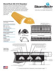
<strong>Tech</strong> <strong>Sheet</strong><br />
Thermoplastic Liners for Detention Systems <strong>Tech</strong> <strong>Sheet</strong> # 2<br />
December, 2012<br />
General:<br />
Storm<strong>Tech</strong> chambers offer the distinct advantage and versatility that allow them to be designed<br />
as an open bottom detention or retention system. In fact the vast majority of Storm<strong>Tech</strong><br />
installations and designs are open bottom detention systems. Using an open bottom system<br />
enables treatment of the storm water through the underlying soils and provides a volume safety<br />
factor based on the infiltrative capacity of the underlying soils.<br />
In some applications, however, open bottom detention systems may not be allowed. This memo<br />
provides guidance for the design and installation of thermoplastic liners for detention systems<br />
using Storm<strong>Tech</strong> chambers. The major points of the memo are:<br />
• Infiltration of stormwater is generally a desirable stormwater management practice, often<br />
required by regulations. Lined systems should only be specified where unique site<br />
conditions preclude significant infiltration.<br />
• Thermoplastic liners provide cost effective and viable means to contain stormwater in<br />
Storm<strong>Tech</strong> subsurface systems where infiltration is undesirable.<br />
• PVC and LLDPE are the most cost effective, installed membrane materials.<br />
• Enhanced puncture resistance from angular aggregate on the water side and from<br />
protrusions on the soil side can be achieved by placing a non-woven geotextile on each<br />
side of the geomembrane. A sand underlayment in lieu of the geotextile on the soil side<br />
may be considered when cost effective.<br />
• Storm<strong>Tech</strong> does not design, fabricate, sell or install thermoplastic liners. Storm<strong>Tech</strong><br />
recommends consulting with liner professionals for final design and installation advice.<br />
Membrane Materials:<br />
Polyvinyl chloride (PVC) is an effective liner material for Storm<strong>Tech</strong> systems. PVC offers<br />
good chemical resistance to contaminant concentrations typical of highway runoff and to<br />
chlorides from road salting applications. Non-reinforced 30 mil PVC liners are recommended for<br />
Storm<strong>Tech</strong> systems. PVC is flexible. It can be folded without damage and is typically<br />
prefabricated and shipped to the jobsite. Panels as large as 20,000 sq. ft. can be prefabricated<br />
into a 4000 lb panel (30 mil is 0.195 lbs/sq. ft., SG = 1.2). PVC has the versatility to be field<br />
solvent welded, taped or field heat welded. A very significant advantage of PVC is that an<br />
excavation contractor can install a PVC liner without specialty crews. Solvent welding of seams,<br />
patches and pipe boots can all be done by the excavation contractor making PVC the lowest<br />
cost liner alternative.<br />
The PVC compound includes fillers and plasticizers to reduce cost and UV inhibitors to extend the<br />
service life under exposure to sunlight. Under prolonged sunlight exposures such as in a<br />
permanent surface pool, these additives can leach into the pool and reach concentrations<br />
70 Inwood Road Suite 3 Rocky Hill, CT 06067 Toll Free 888-892-2694 Fax 866-328-8401 www.stormtech.com<br />
Detention • Retention • Water Quality<br />
A division of
Page 2 of 6<br />
<strong>Tech</strong> <strong>Sheet</strong> #2<br />
harmful to aquatic life. PVC compounds referred to as “fish safe” are sometimes used for surface pond<br />
liners and may be considered for Storm<strong>Tech</strong> liners. However, since Storm<strong>Tech</strong> systems are subsurface,<br />
there is no opportunity for UV attack by sunlight. Also since stormwater is detained for short durations,<br />
typically 48 hours or less, there is little opportunity for accumulation of leachates. Therefore PVC is an<br />
excellent membrane material for thermoplastic liner detention systems.<br />
Recommended Configuration: 30 mil PVC with 8 ounce non-woven geotextile underlayment and<br />
overlayment, open top with high flow bypass.<br />
Recommended Restriction: Do not use for fuel spill containment.<br />
Linear low density polyethylene (LLDPE) is a very inert material that offers excellent chemical<br />
resistance and is “fish safe”. LLDPE is an effective liner system for Storm<strong>Tech</strong> systems, particularly for<br />
small projects where the entire liner can be prefabricated in one piece or when using taped seams.<br />
LLDPE is flexible up to 30 mil but thicknesses greater than 30 mil should not be folded without potential<br />
damage. 30 mil LLDPE is recommended. Extra care should be taken to protect against puncture. A<br />
minimum 8-ounce non-woven fabric underlayment and 12-ounce overlayment should be specified. The<br />
underlayment should be increased to 12-ounce where water tightness is essential and increased puncture<br />
risk exists. Panels as large as 27,000 sq. ft. can be prefabricated into a 4000 lb roll (30 mil is 0.15 lbs/sq.<br />
ft.). LLDPE has a specific gravity less than 1.0. LLDPE seams can be taped or field heat welded.<br />
Installation costs may increase if field seaming by a specialty contractor is required.<br />
Recommended Configuration: 30 mil LLDPE with 8 ounce non-woven geotextile underlayment and<br />
12-ounce overlayment, open top with high flow bypass.<br />
Recommended Restriction: Do not use for fuel spill containment.<br />
Reinforced Polypropylene (RPP), EPDM and XR-5 are excellent materials for lining systems due to their<br />
flexibility, durability and excellent chemical and UV resistance. Although excellent lining materials, they<br />
generally exceed the engineering requirements for typical applications and are higher in cost than PVC or<br />
LLDPE. For fuel and oil concentrations normally found in storm water from parking and roadways, PVC,<br />
LLDPE and PP are suitable. However, if containment of aggressive contaminants, fuels or fuel spills are<br />
anticipated, a liner professional should be consulted. XR-5 in thicknesses of 30 mil or more, with welded<br />
seams may be suitable.<br />
Polyethylene (PE) materials are generally inert, offer excellent chemical resistance and are “fish safe”.<br />
Although medium density polyethylene (MDPE) liners are widely used for sanitary landfills and fish<br />
ponds, they are generally much higher in total cost and are not likely to be cost effective lining materials.<br />
High density polyethylene (HDPE) is not flexible enough to resist puncture and conform to the<br />
excavation. Cost aside, MDPE is an acceptable liner material for Storm<strong>Tech</strong> systems but should be limited<br />
to subgrades that are well prepared, without protrusions and must be field seamed.
Geotextile Materials:<br />
6-ounce AASHTO M288 Class 2 non-woven separation geotextile<br />
over the top of stone (ADS 601 or equal)<br />
8-ounce AASHTO M288 Class 2 non-woven geotextile<br />
for use as protection layer for PVC, RPP and LLDPE (ADS 801 or equal)<br />
Page 3 of 6<br />
<strong>Tech</strong> <strong>Sheet</strong> #2<br />
12-ounce AREMA Chapter 1 Part 10 Category “Regular” non-woven geotextile<br />
for use as protection layer for LLDPE and other PE membranes (ADS 1201 or equal)<br />
Seaming Options:<br />
1. Prefabricated vs. Field Prefabricated seams are preferable to field seams for all liner materials<br />
whenever possible.<br />
2. Solvent Welded PVC only, low cost<br />
3. Heat Welded Costly, require trained seamer, for all liner materials<br />
4. Taped Cost effective, M50-RC Gray distributed by Titus Industrial Group recommended, single<br />
sided, 4” width, for all liner materials. No water tightness data is available.<br />
5. Overlapped Not water tight, no leakage rates available, suggest 4 ft overlap for all materials.<br />
Pipe “boots” are used to seal pipe penetrations through the liner. Boots can either be prefabricated by<br />
the liner fabricator or field fabricated by the contractor. The boot is then solvent cemented, heat welded<br />
or taped to the liner. A pipe clamp is normally used to seal the boot around the pipe. Seaming and<br />
sealing pipe boots at low temperatures (32° F minimum) requires preheating of the material.<br />
Design:<br />
General The design of a lined system must be performed by the consulting engineer and, at minimum,<br />
requires knowledge of design storage, peak flow rates and maximum seasonal high groundwater<br />
elevation. This information is used to design the peak flow control structure, maximum liner height and<br />
groundwater control (if necessary).<br />
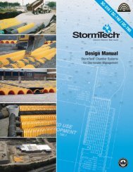
High Flow Bypass A high flow control is an important component for any lined system. The high flow<br />
control is designed to pass the peak flow while ensuring that the liner is not overtopped. The control<br />
structure can be an upstream high flow bypass or a downstream overflow structure. In both cases, a high<br />
flow weir, very similar to the high flow control in a pond outlet control structure, is normally used. The high<br />
flow weir should be sized such that the water surface elevation based on the maximum head on the weir<br />
is less than the top of the liner. Additional freeboard should be provided.<br />
In a typical upstream bypass design, the calculated depth of flow over the weir (H) is subtracted from the<br />
maximum water surface elevation in the chamber system to establish the weir crest elevation. The storage<br />
in the chamber system associated with the weir crest elevation may be a design constraint. The designer<br />
may choose to increase the weir length and therefore decrease the flow depth to establish a higher weir<br />
crest.
The equation for a rectangular weir is:<br />
HIGH FLOW<br />
BYPASS<br />
STRUCTURE<br />
WEIR<br />
H<br />
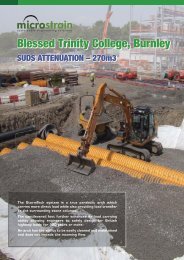
The relationship between bedding thickness and maximum allowable groundwater elevation is:<br />
Hgw<br />
4" HDPE<br />
UNDERDRAIN (TYP.)<br />
t<br />
The bulk density of the open graded stone bedding materials varies from about 75 lbs/ft 3 to over<br />
100 lbs/ft 3 . Without specific bulk density information for the stone actually used, Storm<strong>Tech</strong><br />
recommends using not more than 75 lbs/ft 3.<br />
* The consulting engineer may apply a lower or higher safety factor.<br />
H = (Q / (Cd x L)) 2/3<br />
Where: Q = flow over the weir (cfs)<br />
Cd = discharge coefficient = 3.3<br />
H = Depth of flow over crest (ft)<br />
L = length of weir (ft)<br />
Page 4 of 6<br />
<strong>Tech</strong> <strong>Sheet</strong> #2<br />
In a typical downstream overflow design, the designer may incorporate one or more low flow orifices into<br />
the high flow weir wall. The weir crest is established as described above but hydraulic losses from the inlet<br />
to chamber to the outlet structure may need to be considered. Losses may be factored in by lowering the<br />
weir crest or increasing the liner freeboard.<br />
Buoyancy Storm<strong>Tech</strong> recommends against installing lined chamber systems below groundwater.<br />
Although the total weight of a chamber system generally exceeds the buoyant force, a limiting stability<br />
condition may result when the buoyant pressure exceeds the resistance pressure directly under the<br />
chamber. This could result in a heave of the bedding under the chamber leading to instability. To prevent<br />
adverse impacts from ground water, where gravity discharge is possible, Storm<strong>Tech</strong> recommends the<br />
installation of an underdrain system under the liner. Where there is a potential buoyant force, Storm<strong>Tech</strong><br />
recommends a sufficient stone bedding thickness, such that the weight of stone exceeds the maximum<br />
buoyant force.<br />
The bedding thickness calculation is simplified by ignoring any structural contribution from the liner and<br />
reinforcing material and considering only the weight of the stone in the thinnest area of the bedding, which<br />
is located under the chamber.<br />
Hgw x (62.4 lb/ft 3 ) = ( stone x t) / SF<br />
Where:<br />
Hgw = height of groundwater above liner bottom<br />
(inches)<br />
stone = bulk density of bedding stone (lb/ft 3 )<br />
t = thickness of stone bedding (inches)<br />
SF = safety factor (1.5 typical minimum)*
Page 5 of 6<br />
<strong>Tech</strong> <strong>Sheet</strong> #2<br />
Installation:<br />
Installation should be in accordance with the liner manufacturer’s instructions. Associations<br />
representing membrane materials have developed installation standards and other support documents<br />
for the respective lining materials. Visit their web sites for additional information.<br />
• PVC Geomembrane Institute, University of Illinois, web: http://Pgi-tp.cee.uiuc.edu/forweb<br />
• ”HDPE Geomembrane Installation Specification” by the International Association of Geosynthetic<br />
Installers. Revised February 2000: http://www.iagi.org/specifications.htm<br />
PVC and LLDPE liners should not be installed at temperatures less than 32° F or on windy days. Wind<br />
can catch the liner and be extremely dangerous to laborers. Stones and other protrusions should always<br />
be removed from the excavation. Rolling or compacting is recommended to knock down any remaining<br />
protrusions. The non-woven underlayment fabric is then placed in the excavation, the membrane placed,<br />
and a fabric reinforcement placed over the membrane. Liners are flapped by laborers to get air under the<br />
liner to enable easy drag across bed. Corners are generally formed by folding or “pleating” excess liner<br />
material.<br />
An “anchor trench” about 12” deep by 12” wide may be dug around the top of the excavation to anchor the<br />
top of the reinforcement fabric and thermoplastic liner at the top of the excavation. Stone should be placed<br />
carefully to avoid puncture from long free falls. Similarly, additional care must be taken when spreading<br />
and compacting bedding stone to prevent stones from puncturing the liner during construction.<br />
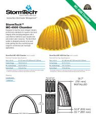
REINFORCEMENT FABRIC<br />
FREEBOARD (FB)<br />
LINED STORAGE (h)<br />
THERMOPLASTIC MEMBRANE<br />
REINFORCEMENT FABRIC<br />
W<br />
ANCHOR<br />
LENGTH<br />
Estimating Liner Material:<br />
Liner fabricators require dimensional details to design panels and provide firm material quotations. The<br />
liner and reinforcing fabric quantities should include sidewalls and extra material for anchoring during<br />
installation. The excavation contractor should use care not to over excavate since a larger excavation<br />
would require additional liner materials.<br />
The fabricated sheet size for estimating purposes is calculated as follows:<br />
Panel Size = [W + 2(h + FB + AL)] x [L + 2(h + FB + AL)]<br />
Where:<br />
W = system width from Storm<strong>Tech</strong> layout drawing<br />
L = system length from Storm<strong>Tech</strong> layout drawing<br />
FB = freeboard based on engineer’s advice (0.5’ typical)<br />
AL = anchor length of membrane and reinforcement to tie back sidewall material<br />
during installation and backfill of chambers (4’ typical)
The location and size of pipe penetrations should also be summarized for the fabricator.<br />
Estimating Worksheet:<br />
L<br />
24" HDPE PIPE PENETRATION (EG.)<br />
Panel Size = [W + 2(h + FB + AL)] x [L + 2(h + FB + AL)]<br />
L<br />
W<br />
AL AL<br />
h + FB<br />
ADS “Terms and Conditions of Sale” are available on the ADS website, www.ads-pipe.com<br />
Storm<strong>Tech</strong> is a registered trademark of Storm<strong>Tech</strong>, Inc.<br />
©2012 Advanced Drainage Systems, Inc. ST TS2 12/12<br />
W<br />
Page 6 of 6<br />
<strong>Tech</strong> <strong>Sheet</strong> #2<br />
W