
Create successful ePaper yourself
Turn your PDF publications into a flip-book with our unique Google optimized e-Paper software.
<strong>StormTech</strong> Construction Guide<br />
REQUIRED MATERIALS AND EQUIPMENT LIST<br />
• Acceptable fill materials per Table 1<br />
• Woven and non-woven geotextiles<br />
• <strong>StormTech</strong> solid end caps and pre-cored end caps<br />
• <strong>StormTech</strong> chambers<br />
Detention • Retention • Water Quality<br />
A division of<br />
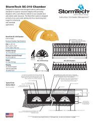
<strong>MC</strong>-<strong>3500</strong>/<strong>MC</strong>-<strong>4500</strong><br />
• <strong>MC</strong>-<strong>3500</strong> end cap screws (2 ½” [64mm] coarse thread – 3 per end cap)<br />
• <strong>MC</strong>-<strong>4500</strong> chamber joint screws (Fastenal #12-11 x 1” slotted hex washer<br />
head sheet metal screw, type A, zinc/steel [SKU 1131123] - 6 per joint)<br />
• <strong>StormTech</strong> manifolds and fittings<br />
NOTE: <strong>MC</strong>-<strong>3500</strong> chamber pallets are 77” x 90” (2.0 m x 2.3 m) and weigh about 2010 lbs. (912 kg) and <strong>MC</strong>-<strong>4500</strong> pallets are 100” x 52” (2.5 m x 1.3 m) and weight<br />
about 840 lbs. (381 kg). Unloading chambers requires 72” (1.8 m) (min.) forks and/or tie downs (straps, chains, etc).<br />
IMPORTANT: This installation guide provides the minimum requirements for proper installation of large chambers. Non-adherence to this guide may result in<br />
damage to chambers during installation. Replacement of damaged chambers during or after backfilling is costly and very time consuming. It is recommended that<br />
all installers are familiar with this guide, and that the contractor inspects the chambers for distortion, damage and joint integrity as work progresses.<br />
Requirements for System Installation<br />
Excavate bed and prepare subgrade per<br />
engineer's plans.<br />
Place non-woven geotextile over prepared soils<br />
and up excavation walls.<br />
Place clean, crushed, angular stone foundation<br />
9" (229 mm) min. Install underdrains if required.<br />
Compact to achieve a flat surface.<br />
Call <strong>StormTech</strong> at 888.892.2694 for technical and product information or visit www.stormtech.com 1
Manifold, Scour Fabric and Chamber Assembly<br />
Install manifolds and lay out woven scour geo -<br />
textile at inlet rows [min. 17.5 ft (5.33 m)] at each<br />
inlet end cap. Place a continuous piece (no<br />
seams) along entire length of Isolator ® Row(s).<br />
Align the first chamber and end cap of each row<br />
with inlet pipes. Each <strong>MC</strong>-<strong>3500</strong> end cap must be<br />
fastened to chambers with three 2 1 ⁄2 " (64 mm) coarse<br />
thread screws before backfilling. Contractor may<br />
choose to postpone stone placement around end<br />
chambers and leave ends of rows open for easy<br />
inspection of chambers during the backfill process.<br />
Manifold Insertion <strong>MC</strong>-<strong>4500</strong> Joint Assembly<br />
Insert inlet and outlet manifolds a minimum 12"<br />
(305 mm) into chamber end caps. Manifold header<br />
should be a minimum 12" (305 mm) from base of<br />
end cap.<br />
12"<br />
12"<br />
WEB SCREW (2)<br />
CREST SCREW<br />
30.0"<br />
Install (6) screws (Fastenal #12-11x1”) at each<br />
<strong>MC</strong>-<strong>4500</strong> joint at locations shown. 3 screws on<br />
each side of joint. Care must be taken to avoid<br />
overtightening and/or “stripping” of screws.<br />
Continue installing chamber rows by overlapping<br />
chamber end corrugations. Chamber joints are<br />
labeled “Lower Joint— Overlap Here” and “Build<br />
This Direction—Upper Joint.” Place non-woven geo -<br />
textile over Isolator Row chambers (if specified).<br />
Maintain minimum - 9" (229 mm) spacing<br />
between rows<br />
CREST<br />
WEB<br />
Install the (2) web screws from the inside of the <strong>MC</strong>-<br />
<strong>4500</strong> chamber 12" (305 mm) above and below the<br />
crest screw.<br />
2
Initial Anchoring of Chambers – Embedment Stone<br />
Initial embedment shall be spotted along the centerline of the chamber evenly<br />
anchoring the lower portion of the chamber. This is best accomplished with a<br />
stone conveyor or excavator reaching along the row.<br />
Backfill of Chambers – Embedment Stone<br />
No equipment shall be operated on the bed at this stage of the installation.<br />
Excavators must be located off the bed. Dump trucks shall not dump stone<br />
directly on to the bed. Dozers or loaders are not allowed on the bed at this time.<br />
UNEVEN BACKFILL EVEN BACKFILL PERIMETER NOT BACKFILLED PERIMETER FULLY BACKFILLED<br />
Backfill chambers evenly. Stone column height should never differ by more than<br />
12” (305 mm) between adjacent chamber rows or between chamber rows and<br />
perimeter.<br />
Perimeter stone must be brought up evenly with chamber rows. Perimeter<br />
must be fully backfilled, with stone extended horizontally to the excavation wall.<br />
Call <strong>StormTech</strong> at 888.892.2694 for technical and product information or visit www.stormtech.com 3
Backfill of Chambers – Embedment Stone and Cover Stone<br />
Continue evenly backfilling between rows and around perimeter until embedment<br />
stone reaches tops of chambers. Perimeter stone must extend horizontally to<br />
the excavation wall for both straight or sloped sidewalls. Only after chambers<br />
have been backfilled to top of chamber and with a minimum 12" (305 mm)<br />
of cover stone on top of chambers can small dozers be used over the<br />
chambers for backfilling remaining cover stone.<br />
Final Backfill of Chambers – Fill Material<br />
Install non-woven geotextile over stone. Geotextile must overlap 24" (610 mm)<br />
min. where edges meet. Compact at 24” (610 mm) of fill. Roller travel parallel<br />
with rows.<br />
Small dozers and skid loaders may be used for cover stone backfill in<br />
accordance with ground pressure limits in Table 2. Dozers must push material<br />
parallel to rows only. Never push perpendicular to rows. <strong>StormTech</strong> recommends<br />
that the contractor inspect chambers before placing final backfill. Any<br />
chambers damaged by construction shall be removed & replaced.<br />
<strong>StormTech</strong> Isolator Row Detail<br />
Call <strong>StormTech</strong> at 888.892.2694 for technical and product information or visit www.stormtech.com 4
Table 1 – Acceptable Fill Materials<br />
Material Location Description AASHTO M43 Compaction/Density<br />
Designation 1 Requirement<br />
D Fill Material for layer ‘D’ starts from Any soil/rock materials, native N/A Prepare per engineer's plans. Paved installations<br />
the top of the ‘C’ layer to the bottom soils or per engineer's plans. Check may have stringent material and preparation<br />
of flexible pavement or unpaved finished plans for pavement subgrade requirements.<br />
grade above. Note that the pavement requirements.<br />
subbase may be part of the ‘D’ layer.<br />
C Fill Material for layer ‘C’ starts from Granular well-graded soil/aggregate 3, 357, 4, 467, 5, Begin compaction after min. 24" (610 mm) of material<br />
the top of the embedment stone (‘B’ layer) mixtures,
Table 2 – Maximum Allowable Construction Vehicle Loads6 D Final Fill 36" [914] 32,000 [142] 16,000 [71] 12" [305] 3420 [164]<br />
38,000 [169]<br />
Material Compacted<br />
18" [457]<br />
24" [610]<br />
2350 [113]<br />
1850 [89]<br />
30" [762] 1510 [72]<br />
36" [914] 1310 [63]<br />
24" [610] 32,000 [142] 16,000 [71] 12" [305] 2480 [119]<br />
20,000 [89]<br />
Compacted<br />
18" [457]<br />
24" [610]<br />
1770 [85]<br />
1430 [68]<br />
30" [762] 1210 [58]<br />
36" [914] 1070 [51]<br />
24" [610] 24,000 [107] 12,000 [53] 12" [305] 2245 [107]<br />
16,000 [71]<br />
Loose/Dumped<br />
18" [457]<br />
24" [610]<br />
1625 [78]<br />
1325 [63]<br />
30" [762] 1135 [54]<br />
36" [914] 1010 [48]<br />
18" [457] 24,000 [107] 12,000 [53] 12" [305]<br />
18" [457]<br />
24” [610]<br />
2010 [96]<br />
1480 [71]<br />
1220 [58]<br />
5,000 [22]<br />
(static loads only)<br />
30” [762] 1060 [51]<br />
5<br />
Maximum Allowable Wheel Loads Maximum Allowable Track Loads Maximum Allowable Roller Loads<br />
Material Fill Depth Max Axle Load Max Wheel Load Track Max Ground Max Drum Weight<br />
Location over Chambers for Trucks<br />
C Initial Fill<br />
Material<br />
B Embedment 12" [305] NOT ALLOWED NOT ALLOWED 12" [305] 1100 [53]<br />
NOT ALLOWED<br />
Stone<br />
18" [457]<br />
24" [610]<br />
715 [34]<br />
660 [32]<br />
30" [762] 580 [28]<br />
6" [152] NOT ALLOWED NOT ALLOWED NOT ALLOWED NOT ALLOWED NOT ALLOWED<br />
1,2 for Loaders Width Pressure3 or Dynamic Force<br />
in. [mm] lbs [kN] lbs [kN] in. [mm] psf [kPa] lbs [kN]<br />
Table 3 – Placement Methods and Descriptions<br />
Material Placement Wheel Load Track Load Roller Load<br />
Location Methods/ Restrictions Restrictions Restrictions<br />
Restrictions See Table 2 for Maximum Construction Loads<br />
D Final Fill<br />
Material<br />
C Initial Fill<br />
Material<br />
B Embedment<br />
Stone<br />
A Foundation<br />
Stone<br />
A variety of placement methods may be<br />
used. All construction loads must not<br />
exceed the maximum limits in Table 2.<br />
Excavator positioned off bed recommended.<br />
Small excavator allowed over<br />
chambers. Small dozer allowed.<br />
No equipment allowed on bare chambers.<br />
Use excavator or stone conveyor<br />
positioned off bed or on foundation<br />
stone to evenly fill around all chambers<br />
to at least the top of chambers.<br />
36" (914 mm) minimum<br />
cover required for dump<br />
trucks to dump over<br />
chambers.<br />
Asphalt can be dumped into<br />
paver when compacted<br />
pavement subbase reaches<br />
24" (610 mm) above top of<br />
chambers.<br />
No wheel loads allowed.<br />
Material must be dumped<br />
outside the limits of the<br />
chamber bed.<br />
Dozers to push parallel to<br />
rows. 4<br />
Small LGP track dozers & skid<br />
loaders allowed to spread<br />
embedment stone with at least<br />
12” (305 mm) stone under<br />
tracks at all times. Dozers to<br />
push parallel to rows only<br />
Roller travel parallel to rows<br />
only until 36” (914 mm)<br />
compacted cover is<br />
reached.<br />
Use dynamic force of roller<br />
only after compacted fill<br />
depth reaches 24" (610 mm)<br />
over chambers. Roller travel<br />
parallel to chamber rows only.<br />
No rollers allowed.<br />
No <strong>StormTech</strong> restrictions. Contractor responsible for any conditions or requirements by others relative to subgrade bearing<br />
capacity, dewatering or protection of subgrade.<br />
NOTES:<br />
1. 36" (914 mm) of stabilized cover materials over the chambers is<br />
required for full dump truck travel and dumping.<br />
2. During paving operations, dump truck axle loads on 24”<br />
(610 mm) of cover may be necessary. Precautions should be<br />
taken to avoid rutting of the road base layer, to ensure that<br />
compaction requirements have been met, and that a minimum<br />
of 24” (610 mm) of cover exists over the chambers. Contact<br />
<strong>StormTech</strong> for additional guidance on allowable axle loads<br />
during paving.<br />
3. Ground pressure for track dozers is the vehicle operating<br />
weight divided by total ground contact area for both tracks.<br />
Excavators will exert higher ground pressures based on<br />
loaded bucket weight and boom extension. Excavators shall<br />
not operate on chamber beds until the total backfill reaches<br />
3 feet (914 mm).<br />
4. Mini-excavators can be used with at least 12” (305 mm)<br />
of stone over the chambers and are limited by the maximum<br />
ground pressures in Table 2 based on a full bucket at<br />
maximum boom extension.<br />
5. <strong>StormTech</strong> does not require compaction of initial fill at 18”<br />
(457 mm) of cover. However, requirements by others for 6”<br />
(152 mm) lifts may necessitate the use of small compactors at<br />
18” (457 mm) of cover.<br />
6. Storage of materials such as construction materials,<br />
equipment, spoils, etc. should not be located over the<br />
<strong>StormTech</strong> system. The use of equipment over the<br />
<strong>StormTech</strong> system not covered in Table 2 (ex. soil mixing<br />
equipment, cranes, etc) is limited. Please contact <strong>StormTech</strong><br />
for more information.<br />
ADS “Terms and Conditions of Sale” are available on the ADS website,<br />
www.ads-pipe.com.<br />
Advanced Drainage Systems, the ADS logo, and the green stripe are<br />
registered trademarks of Advanced Drainage Systems.<br />
<strong>StormTech</strong> ® and the Isolator ® Row are registered trademarks of<br />
<strong>StormTech</strong>, Inc<br />
#10816 08/12<br />
©2012 Advanced Drainage Systems, Inc.<br />
Call <strong>StormTech</strong> at 888.892.2694 for technical and product information or visit www.stormtech.com 6