Trend in Optical Fibers and Cables for Fiber-To-The-Home
Trend in Optical Fibers and Cables for Fiber-To-The-Home
Trend in Optical Fibers and Cables for Fiber-To-The-Home

You also want an ePaper? Increase the reach of your titles
YUMPU automatically turns print PDFs into web optimized ePapers that Google loves.
64<br />
Feature Articles: <strong>Optical</strong> <strong>Fiber</strong> Communications<br />
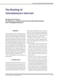
pared with the step <strong>in</strong>dex profile.<br />
As an example, simulated <strong>and</strong> measured bend<strong>in</strong>g<br />
loss at 1650 nm as a function of bend<strong>in</strong>g radius <strong>for</strong><br />
fibers with the trench-<strong>in</strong>dex <strong>and</strong> step-<strong>in</strong>dex profiles<br />
Fig�� Fig�� Fig�� Fig�� Fig�� Simulated Simulated Simulated <strong>and</strong> <strong>and</strong> measured measured bend<strong>in</strong>g bend<strong>in</strong>g loss loss at at ����nm ����nm ����nm ����nm ����nm as as a a func� func� func� func� func�<br />
tion tion of of bend<strong>in</strong>g bend<strong>in</strong>g radius radius <strong>for</strong> <strong>for</strong> <strong>for</strong> fibers fibers with with trench�<strong>in</strong>dex trench�<strong>in</strong>dex trench�<strong>in</strong>dex trench�<strong>in</strong>dex trench�<strong>in</strong>dex <strong>and</strong> <strong>and</strong> step�<strong>in</strong>dex step�<strong>in</strong>dex step�<strong>in</strong>dex step�<strong>in</strong>dex step�<strong>in</strong>dex<br />
profiles� profiles� profiles� profiles� profiles�<br />
are shown <strong>in</strong> Fig.7. <strong>The</strong> bend<strong>in</strong>g loss of the fiber with<br />
a trench <strong>in</strong>dex profile is lower than that<br />
of the fiber with a step <strong>in</strong>dex profile. A<br />
mechanical splice loss between the<br />
fiber <strong>and</strong> C-SMF is 0.15 dB <strong>in</strong> average<br />
<strong>and</strong> 0.03 dB <strong>in</strong> st<strong>and</strong>ard deviation,<br />
which is acceptable <strong>for</strong> practical use.<br />
V. EASY-HANDLING Ø0.5<br />
-MM OPTICAL FIBER<br />
It has been necessary to simplify the<br />
<strong>in</strong>stallation of cables <strong>and</strong> to reduce<br />
construction time to popularize FTTH.<br />
A fiber with thicker coat<strong>in</strong>g than the<br />
conventional fiber with a diameter of<br />
0.25 mm is expected to ease the h<strong>and</strong>l<strong>in</strong>g<br />
<strong>in</strong> <strong>in</strong>stallation <strong>and</strong> connection.<br />
However, commercially available connection<br />
tools <strong>and</strong> devices <strong>for</strong> FTTH are<br />
specialized <strong>for</strong> Ø 0.25-mm fiber.<br />
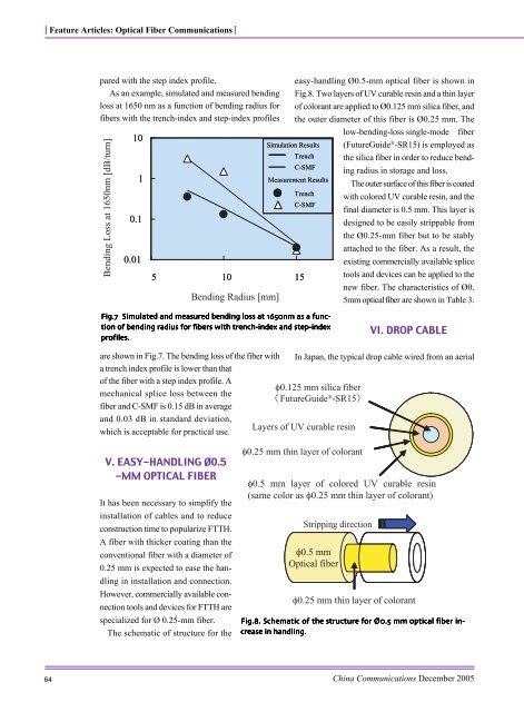
<strong>The</strong> schematic of structure <strong>for</strong> the<br />
easy-h<strong>and</strong>l<strong>in</strong>g Ø0.5-mm optical fiber is shown <strong>in</strong><br />
Fig.8. Two layers of UV curable res<strong>in</strong> <strong>and</strong> a th<strong>in</strong> layer<br />
of colorant are applied to Ø0.125 mm silica fiber, <strong>and</strong><br />
the outer diameter of this fiber is Ø0.25 mm. <strong>The</strong><br />
low-bend<strong>in</strong>g-loss s<strong>in</strong>gle-mode fiber<br />
(FutureGuide ® -SR15) is employed as<br />
the silica fiber <strong>in</strong> order to reduce bend<strong>in</strong>g<br />
radius <strong>in</strong> storage <strong>and</strong> loss.<br />
<strong>The</strong> outer surface of this fiber is coated<br />
with colored UV curable res<strong>in</strong>, <strong>and</strong> the<br />
f<strong>in</strong>al diameter is 0.5 mm. This layer is<br />
designed to be easily strippable from<br />
the Ø0.25-mm fiber but to be stably<br />
attached to the fiber. As a result, the<br />
exist<strong>in</strong>g commercially available splice<br />
tools <strong>and</strong> devices can be applied to the<br />
new fiber. <strong>The</strong> characteristics of Ø0.<br />
5mm optical fiber are shown <strong>in</strong> Table 3.<br />
VI. DROP CABLE<br />
In Japan, the typical drop cable wired from an aerial<br />
Fig��� Fig��� Fig��� Fig��� Fig��� Schematic Schematic Schematic of of the the structure structure <strong>for</strong> <strong>for</strong> ��� ��� ��� ��� ��� mm mm mm optical optical fiber fiber <strong>in</strong>� <strong>in</strong>� <strong>in</strong>� <strong>in</strong>� <strong>in</strong>�<br />
crease crease <strong>in</strong> <strong>in</strong> h<strong>and</strong>l<strong>in</strong>g� h<strong>and</strong>l<strong>in</strong>g� h<strong>and</strong>l<strong>in</strong>g�<br />
h<strong>and</strong>l<strong>in</strong>g� h<strong>and</strong>l<strong>in</strong>g�<br />
Ch<strong>in</strong>a Communications December 2005