Trend in Optical Fibers and Cables for Fiber-To-The-Home
Trend in Optical Fibers and Cables for Fiber-To-The-Home
Trend in Optical Fibers and Cables for Fiber-To-The-Home

Create successful ePaper yourself
Turn your PDF publications into a flip-book with our unique Google optimized e-Paper software.
ABSTRACT<br />
<strong>The</strong> configuration of optical fiber cables deployed <strong>in</strong><br />
Japan <strong>and</strong> the requirements <strong>for</strong> FTTH are described.<br />
<strong>The</strong> optical fiber used <strong>in</strong> FTTH is <strong>in</strong>troduced, <strong>and</strong><br />
bend<strong>in</strong>g loss improvement <strong>and</strong> transmission range<br />
expansion are described. <strong>Optical</strong> fiber cables which<br />
meet the requirements peculiar to FTTH are also<br />
<strong>in</strong>troduced <strong>and</strong> reviewed.<br />
Key words: FTTH, optical fiber cable, FTTX,<br />
Japan<br />
I. INTRODUCTION<br />
In Japan, "e-Japan Strategy" was <strong>for</strong>mulated <strong>in</strong> January<br />
2001 with the goal of mak<strong>in</strong>g Japan "the most<br />
advanced IT nation <strong>in</strong> the world by 2005" [1] . <strong>To</strong>day,<br />
the improvement of Japanese broadb<strong>and</strong> <strong>in</strong>frastructure<br />
is accelerated by the strategy, <strong>and</strong> broadb<strong>and</strong><br />
networks are available <strong>for</strong> the lowest cost <strong>and</strong> the<br />
fastest speed <strong>in</strong> the world. <strong>The</strong> number of broadb<strong>and</strong><br />
subscribers <strong>in</strong>clud<strong>in</strong>g <strong>Fiber</strong> <strong>To</strong> <strong>The</strong> <strong>Home</strong> (FTTH),<br />
Digital Scriber L<strong>in</strong>e (DSL), cable <strong>in</strong>ternet, <strong>and</strong> wireless<br />
such as Fixed Wireless Access (FWA) has<br />
reached about 20 million. <strong>To</strong>day DSL subscribers<br />
account <strong>for</strong> about 70% of total broadb<strong>and</strong> subscribers,<br />
but its quarterly <strong>in</strong>crement tends to reduce. In contrast,<br />
the number of FTTH subscribers reached about 2.9<br />
million <strong>in</strong> March 2004, <strong>and</strong> its quarterly <strong>in</strong>crement<br />
tends to <strong>in</strong>crease. Thus it is anticipated that the<br />
number of FTTH subscribers will surpass the num-<br />
Feature Articles: <strong>Optical</strong> <strong>Fiber</strong> Communications<br />
<strong>Trend</strong> <strong>in</strong> <strong>Optical</strong> <strong><strong>Fiber</strong>s</strong> <strong>and</strong> <strong>Cables</strong> <strong>for</strong><br />
<strong>Fiber</strong>-<strong>To</strong>-<strong>The</strong>-<strong>Home</strong><br />
Takahiro Hamada , Shoichiro Matsuo , Kuniharu Himeno<br />
Fujikura Ltd. Optics <strong>and</strong> Electronics Laboratory, Japan<br />
ber of DSL subscribers <strong>in</strong> the near future [2] .<br />
In order to support the cont<strong>in</strong>u<strong>in</strong>g spread of FTTH<br />
cost reduction of materials used <strong>in</strong> FTTH <strong>and</strong> simplification<br />
of construction are required. As a result<br />
optical fibers <strong>and</strong> cables with per<strong>for</strong>mances peculiar<br />
to FTTH are desired. In the next section, we describe<br />
the configuration of optical fiber cables deployed <strong>in</strong><br />
Japan <strong>and</strong> requirements <strong>for</strong> them. In section 3 <strong>and</strong> 4,<br />
we <strong>in</strong>troduce the optical fiber used <strong>in</strong> FTTH, <strong>and</strong><br />
describe its bend<strong>in</strong>g loss improvement <strong>and</strong> transmission<br />
range expansion. In the rest of the report, we<br />
<strong>in</strong>troduce optical fiber cables which meet the requirements<br />
peculiar to FTTH.<br />
II. CONFIGURATION OF OPTICAL<br />
FIBER CABLES FOR FTTH IN JAPAN<br />
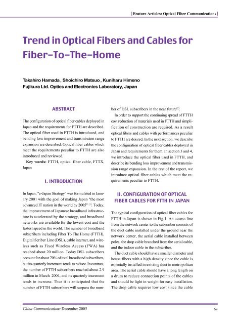
<strong>The</strong> typical configuration of optical fiber cables <strong>for</strong><br />
FTTH <strong>in</strong> Japan is shown <strong>in</strong> Fig.1. An access l<strong>in</strong>e<br />
from the network center to the subscriber consists of<br />
the duct cable <strong>in</strong>stalled under the ground near the<br />
network center, the aerial cable <strong>in</strong>stalled between<br />
poles, the drop cable branched from the aerial cable,<br />
<strong>and</strong> the <strong>in</strong>door cable <strong>in</strong> the subscriber.<br />
<strong>The</strong> duct cable should have a smaller diameter <strong>and</strong><br />
house fibers with a high density s<strong>in</strong>ce the cable is<br />
especially <strong>in</strong>stalled <strong>in</strong> exist<strong>in</strong>g duct <strong>in</strong> metropolitan<br />
area. <strong>The</strong> aerial cable should have a long length on<br />
a drum to reduce connection po<strong>in</strong>ts of the cables<br />
<strong>and</strong> should be light <strong>in</strong> weight <strong>for</strong> easy <strong>in</strong>stallation.<br />
<strong>The</strong> drop cable requires low cost s<strong>in</strong>ce the cable<br />
Ch<strong>in</strong>a Communications December 2005 59
60<br />
Feature Articles: <strong>Optical</strong> <strong>Fiber</strong> Communications<br />
cost directly account <strong>for</strong> a cost per subscriber, <strong>and</strong><br />
should be able to be h<strong>and</strong>led easily <strong>for</strong> quick <strong>and</strong><br />
economical <strong>in</strong>stallation.<br />
A surplus optical fiber took out from the cables is<br />
wound <strong>and</strong> stored <strong>in</strong> a closure or a cab<strong>in</strong>et. In<br />
particular, the fiber <strong>in</strong> the drop cable is required to<br />
be able to be bent small to downsize the closure<br />
<strong>and</strong> the cab<strong>in</strong>et. Furthermore, a fiber <strong>in</strong> an <strong>in</strong>door<br />
cable may be bent with a small curvature <strong>for</strong> wir<strong>in</strong>g<br />
along a wall <strong>and</strong> <strong>for</strong> storage.<br />
Fig�� Fig�� Fig�� Fig�� Fig�� Configuration Configuration of of cables cables <strong>in</strong> <strong>in</strong> <strong>in</strong> FTTH� FTTH� FTTH� FTTH� FTTH�<br />
3. OPTICAL FIBER USED IN FTTH<br />
<strong>The</strong> structure of a silica optical fiber, which is the<br />
most popular optical fiber <strong>in</strong> telecommunications, is<br />
shown <strong>in</strong> Fig.2. <strong>The</strong> fiber consists of a cladd<strong>in</strong>g<br />
which is made from silica <strong>and</strong> a core whose refractive<br />
<strong>in</strong>dex is raised slightly higher than that of the<br />
Fig�� Fig�� Fig�� Fig�� Fig�� Structure Structure of of silica silica optical optical fiber� fiber� fiber� fiber� fiber� (a) (a) dimensions� dimensions� dimensions� dimensions� dimensions� (b)<br />
(b)<br />
refractive refractive <strong>in</strong>dex <strong>in</strong>dex profile� profile� profile�<br />
profile� profile�<br />
cladd<strong>in</strong>g by dop<strong>in</strong>g germanium.<br />
Light can be conf<strong>in</strong>ed with<strong>in</strong> the core by the coreto<br />
-cladd<strong>in</strong>g <strong>in</strong>dex difference. <strong>The</strong> structure is characterized<br />
by the core diameter 2a <strong>and</strong> the relative<br />
refractive <strong>in</strong>dex difference Light conf<strong>in</strong>ed <strong>in</strong> the<br />
fiber propagates at a very small attenuation, e.g. 0.<br />
2-0.3 dB/km. <strong>The</strong> cladd<strong>in</strong>g diameter is 125 µm, <strong>and</strong><br />
the cladd<strong>in</strong>g is coated with plastic res<strong>in</strong> to a diameter<br />
of 250 µm.<br />
<strong>The</strong> optical fiber has two ma<strong>in</strong> categories; a multimode<br />
fiber <strong>and</strong> a s<strong>in</strong>gle-mode fiber. <strong>The</strong><br />
core diameter of the multimode fiber is 50<br />
µm <strong>and</strong> the fiber is easy to connect with each<br />
other <strong>and</strong> with an <strong>in</strong>expensive light source,<br />
so that the fiber is applied to short distance<br />
communications. <strong>The</strong> s<strong>in</strong>gle-mode fiber<br />
whose core diameter is about 10 µm is applied<br />
to high-speed <strong>and</strong>/or long-distance communications<br />
s<strong>in</strong>ce more sophisticated techniques<br />
are required to connect with each<br />
other <strong>and</strong> with optical devices.<br />
<strong>The</strong> fiber with an <strong>in</strong>dex profile as shown <strong>in</strong><br />
Fig.2 can be operated as a s<strong>in</strong>gle-mode fiber<br />
when the normalized frequency V def<strong>in</strong>ed as the follow<strong>in</strong>g<br />
equation is less than 2.405 at a wavelength of .<br />
(1)<br />
(2)<br />
Possible comb<strong>in</strong>ations of parameters which<br />
result <strong>in</strong> s<strong>in</strong>gle-mode operation are <strong>in</strong>f<strong>in</strong>itely.<br />
However, the dimensions <strong>and</strong> properties of "the<br />
s<strong>in</strong>gle-mode fiber" <strong>for</strong> telecommunications are<br />
def<strong>in</strong>ed <strong>in</strong> ITU-T Recommendation G.652.<br />
In Japan, the s<strong>in</strong>gle-mode fiber comply<strong>in</strong>g G.<br />
652 are used even <strong>in</strong> FTTH whereas FTTH<br />
covers short distance <strong>and</strong> requires economical<br />
materials. This is because arc-fusion splice <strong>and</strong><br />
connector <strong>for</strong> the fiber have been highly developed<br />
<strong>and</strong> the cost of optical devices <strong>for</strong> the fiber<br />
has become reasonable.<br />
3.1 Solution <strong>for</strong> small bend<strong>in</strong>g radius<br />
An optical fiber <strong>for</strong> a drop cable or an <strong>in</strong>door<br />
Ch<strong>in</strong>a Communications December 2005
cable should be able to be bent <strong>in</strong> a smaller curvature<br />
as described <strong>in</strong> Section 2. However, the fiber bent <strong>in</strong><br />
a small radius causes transmission loss, which is<br />
called the bend<strong>in</strong>g loss.<br />
A s<strong>in</strong>gle-mode fiber with a smaller mode field<br />
diameter (MFD) has a lower bend<strong>in</strong>g loss. MFD may<br />
be reduced by enhanc<strong>in</strong>g the refractive <strong>in</strong>dex of the<br />
core <strong>and</strong> reduce the core diameter so as to keep the<br />
s<strong>in</strong>gle-mode conditions shown <strong>in</strong> Eq. (1).<br />
We have developed FutureGuide ® -SR15, which<br />
can achieve a negligibly low bend<strong>in</strong>g loss at a bend<strong>in</strong>g<br />
radius of 15 mm by slightly enhanc<strong>in</strong>g the<br />
refractive <strong>in</strong>dex of the core. This allowable bend<strong>in</strong>g<br />
Feature Articles: <strong>Optical</strong> <strong>Fiber</strong> Communications<br />
radius is a half of that of the conventional s<strong>in</strong>glemode<br />
fiber (C-SMF). <strong>The</strong> wavelength dependences<br />
of the bend<strong>in</strong>g losses <strong>for</strong> FutureGuide ® -SR15 <strong>and</strong> C-<br />
SMF are shown <strong>in</strong> Fig.3 [3] .<br />
<strong>The</strong> bend<strong>in</strong>g loss <strong>for</strong> FutureGuide ® -SR15 is about<br />
one-tenth of that <strong>for</strong> C-SMF. <strong>The</strong> bend<strong>in</strong>g loss at<br />
longer wavelength <strong>in</strong>creases as shown <strong>in</strong> Fig.4 s<strong>in</strong>ce<br />
the MFD at a longer wavelength becomes larger.<br />
<strong>The</strong> characteristics of FutureGuide ® -SR15 <strong>and</strong><br />
ITU-T recommendation G.652.B are shown <strong>in</strong> Table<br />
1. <strong>The</strong> allowable bend<strong>in</strong>g radius of FutureGuide ® -<br />
SR15 is a half of that of ITU-T recommendation G.<br />
652.B. <strong>The</strong> typical MFD of FutureGuide ® -<br />
SR15 is smaller than that of ITU-T recommendation<br />
G.652.B. However,<br />
FutureGuide ® -SR15 is applicable to all regions<br />
<strong>in</strong> FTTH <strong>and</strong> even <strong>in</strong> trunk l<strong>in</strong>es s<strong>in</strong>ce<br />
all characteristics of FutureGuide ® -SR15<br />
complies with G.652.B.<br />
3.2 Solution <strong>for</strong> wideb<strong>and</strong> transmission<br />
Wavelengths used <strong>for</strong> the optical communications<br />
are def<strong>in</strong>ed as shown <strong>in</strong> Fig.4. Even<br />
Fig�� Fig�� Fig�� Fig�� Fig�� Wavelength Wavelength dependence dependence dependence of of b<strong>in</strong>d<strong>in</strong>g b<strong>in</strong>d<strong>in</strong>g loss loss on<br />
on<br />
<strong>in</strong> FTTH, Wavelength Division Multiplex-<br />
FutureGuide<br />
FutureGuide FutureGuide<br />
<strong>in</strong>g (WDM)<br />
is used to<br />
construct<br />
passive optical<br />
networks<br />
(PON) to<br />
save the<br />
number of<br />
optical fibers<br />
per<br />
subscriber.<br />
In WDM <strong>for</strong><br />
FTTH, Ctransmission<br />
b<strong>and</strong> is used<br />
<strong>for</strong> downstreamtransmission<br />
® �SR�� �SR�� �SR�� �SR�� �SR�� <strong>and</strong> <strong>and</strong> C�SMF C�SMF C�SMF C�SMF C�SMF at at ø�� ø�� ø�� ø�� ø�� mm mm <strong>and</strong> <strong>and</strong> �� �� �� �� �� turn� turn� turn� turn� turn�<br />
Table.1 Characteristics of FutureGuide ® -SR15 <strong>and</strong> ITU-T recommendation G.652.B.<br />
Ch<strong>in</strong>a Communications December 2005 61
62<br />
Feature Articles: <strong>Optical</strong> <strong>Fiber</strong> Communications<br />
from a network center to a subscriber, <strong>and</strong> O-trans- s<strong>in</strong>ter<strong>in</strong>g the glass particles.<br />
mission b<strong>and</strong> is used <strong>for</strong> upstream transmission from It has been reported that the fiber without OH<br />
the subscriber to the network center. In addition, the absorption peak can be made by optimization of<br />
new system that uses C-transmission b<strong>and</strong> <strong>for</strong> broad- dehydration conditions <strong>and</strong> fiber structure <strong>in</strong> the<br />
cast<strong>in</strong>g <strong>and</strong> O-transmission b<strong>and</strong> <strong>and</strong> S-transmission 1980s<br />
b<strong>and</strong> <strong>for</strong> optical communications has started to be<br />
deployed. WDM-PON us<strong>in</strong>g more wavelengths is <strong>in</strong><br />
research towards a future FTTH system.<br />
In C-SMF, E-transmission b<strong>and</strong> is not used <strong>for</strong><br />
[5-7] . Recently, this type of fiber, "low water<br />
peak fiber," has been commercialized <strong>and</strong><br />
st<strong>and</strong>ardized. We also have developed FutureGuide ® -<br />
SR15E, which have both low bend<strong>in</strong>g loss <strong>and</strong> low<br />
water peak. <strong>The</strong> spectral attenuations of<br />
FutureGuide ® -SR15E <strong>and</strong> C-SMF are<br />
shown <strong>in</strong> Fig.5. FutureGuide ® -SR15E<br />
has a low OH absorption <strong>and</strong> can be<br />
used <strong>for</strong> optical communications at Etransmission<br />
b<strong>and</strong> [3,8] .<br />
Expos<strong>in</strong>g an optical fiber to hydrogen<br />
may result <strong>in</strong> the <strong>in</strong>crease of an<br />
attenuation at 1383 nm [9,10] . <strong>The</strong>re<strong>for</strong>e,<br />
the upper attenuation value of a low-<br />
Fig�� Fig�� Fig�� Fig�� Fig�� Wavelengths Wavelengths used used <strong>for</strong> <strong>for</strong> <strong>for</strong> the the optical optical communication�<br />
communication�<br />
communication�<br />
communication�<br />
communication�<br />
water-peak fiber after hydrogen ag<strong>in</strong>g<br />
optical communications due to possible larger<br />
attenuation at 1383 nm. <strong>The</strong> attenuation at<br />
1383 nm results from the second overtone<br />
of the fundamental Si-OH vibration at 2700<br />
nm. OH groups <strong>in</strong> a pre<strong>for</strong>m must be elim<strong>in</strong>ated<br />
<strong>for</strong> decreas<strong>in</strong>g the attenuation at 1383<br />
nm.<br />
An optical fiber pre<strong>for</strong>m is made of SiO2 from SiCl through the thermal oxidation<br />
4<br />
<strong>and</strong>/or the hydrolysis reaction.<br />
As <strong>for</strong> the per<strong>for</strong>m synthesis methods<br />
us<strong>in</strong>g the thermal oxidation reaction, such as<br />
the MCVD <strong>and</strong> the PCVD methods, the reduction of<br />
OH-groups conta<strong>in</strong>ed <strong>in</strong> raw material, a substrate<br />
<strong>and</strong> a jacket<strong>in</strong>g tubes, <strong>and</strong> modification of the apparatus<br />
<strong>for</strong> tighter gas leak have been attempted to<br />
reduce the absorption at 1383 nm [4] test (IEC60793-2-50) is def<strong>in</strong>ed by ITU-T G.652.C<br />
<strong>and</strong> G.652.D. <strong>The</strong> attenuations of FutureGuide<br />
.<br />
As <strong>for</strong> the per<strong>for</strong>m synthesis methods us<strong>in</strong>g the<br />
hydrolysis reaction, such as the VAD <strong>and</strong> the OVD<br />
methods, OH-groups <strong>in</strong> glass particles generate<br />
<strong>in</strong>herently. <strong>The</strong>re<strong>for</strong>e, when a pre<strong>for</strong>m is made by the<br />
hydrolysis, OH-groups <strong>in</strong> the pre<strong>for</strong>m is elim<strong>in</strong>ated<br />
by the dehydration process <strong>in</strong> which a soot per<strong>for</strong>m<br />
is heated <strong>in</strong> the presence of Cl or SOCl be<strong>for</strong>e<br />
2 2 ® -<br />
SR15E <strong>and</strong> ITU-T G.652.D are shown <strong>in</strong> Table 2.<br />
<strong>The</strong> characteristics of FutureGuide ® -SR15E other<br />
than those shown <strong>in</strong> Table 2 are the same as the<br />
characteristics of FutureGuide ® -SR15 shown <strong>in</strong> Table<br />
1. FutureGuide ® -SR15E has an allowable bend<strong>in</strong>g<br />
radius of 15 mm <strong>and</strong> is compliant with ITU-T Recommendation<br />
G.652. As a result, FutureGuide ® Fig�� Fig�� Fig�� Fig�� Fig�� Spectral Spectral attenuations attenuations of of FutureGuide FutureGuide<br />
-<br />
SR15E can be used <strong>for</strong> broadb<strong>and</strong> WDM transmission<br />
l<strong>in</strong>e <strong>in</strong> access <strong>and</strong> core networks.<br />
® �SR��E �SR��E �SR��E �SR��E �SR��E <strong>and</strong> <strong>and</strong> <strong>and</strong> C�SMF� C�SMF� C�SMF�<br />
C�SMF� C�SMF�<br />
Ch<strong>in</strong>a Communications December 2005
Increas<strong>in</strong>g the relative-<strong>in</strong>dex difference<br />
between the core <strong>and</strong> the cladd<strong>in</strong>g results<br />
<strong>in</strong> decreas<strong>in</strong>g a bend<strong>in</strong>g loss but decreas<strong>in</strong>g<br />
a MFD. If two fibers with Gaussian<br />
electric fields <strong>and</strong> with MFDs of 2W <strong>and</strong> 1<br />
2W , the connection loss <strong>in</strong> dB, Ls,<br />
2<br />
between the fibers can be calculated by<br />
Eq. (3).<br />
(3)<br />
Obviously, the connection loss is m<strong>in</strong>imized when<br />
W =W . When an optical fiber with an enhanced<br />
1 2<br />
Feature Articles: <strong>Optical</strong> <strong>Fiber</strong> Communications<br />
IV. NEW OPTICAL FIBER IN<br />
DEVELOPMENT FOR FURTHER<br />
BENDING LOSS IMPROVEMENT<br />
We so far have described fibers with a simple refractive-<strong>in</strong>dex<br />
profile called as the step-<strong>in</strong>dex profile as<br />
shown <strong>in</strong> Fig.2 (b). In addition to the requirements<br />
<strong>for</strong> an <strong>in</strong>door cable as described <strong>in</strong> section 2, the<br />
cable is desired to be able to be h<strong>and</strong>led without<br />
worry<strong>in</strong>g about bend<strong>in</strong>g just like a metal<br />
cable [11] core refractive <strong>in</strong>dex <strong>for</strong><br />
reduction of bend<strong>in</strong>g loss<br />
is connected with C-<br />
SMF, connection loss <strong>in</strong>creases<br />
accord<strong>in</strong>g as the<br />
MFD difference between<br />
those two fibers.<br />
A fiber with improved<br />
bend<strong>in</strong>g loss <strong>for</strong> an <strong>in</strong>door<br />
cable should be connected<br />
with C-SMF applied <strong>in</strong> a<br />
drop cable <strong>and</strong> an optical<br />
network unit (ONU) <strong>in</strong> a<br />
subscriber. <strong>The</strong>re<strong>for</strong>e, we<br />
should consider not only<br />
bend<strong>in</strong>g loss but also MFD of the fiber so as to<br />
ma<strong>in</strong>ta<strong>in</strong> its MFD as large as that of C-SMF, 9.2 µm.<br />
We have proposed an improved bend<strong>in</strong>g loss fiber<br />
with a refractive <strong>in</strong>dex profile as shown <strong>in</strong> Fig.6<br />
. In this section, we <strong>in</strong>troduce the<br />
fiber which has a new refractive-<strong>in</strong>dex<br />
profile so as to achieve advanced bend<strong>in</strong>g<br />
loss properties.<br />
[12] Table 2. Attenuations of FutureGuide<br />
.<br />
<strong>The</strong> feature of the profile is that "trench" with a lower<br />
refractive-<strong>in</strong>dex than that of the fused silica locates<br />
between the <strong>in</strong>ner cladd<strong>in</strong>g around the core <strong>and</strong> the<br />
outer cladd<strong>in</strong>g. <strong>The</strong> <strong>in</strong>dex trench at the edge of the<br />
mode field works to conf<strong>in</strong>e the mode field stronger<br />
® -SR15E.<br />
Fig�� Fig�� Fig�� Fig�� Fig�� Schematic Schematic of of trench trench trench <strong>in</strong>dex <strong>in</strong>dex profile� profile� profile� profile� profile�<br />
than the step <strong>in</strong>dex profile even if MFD of the fiber is<br />
the same as that <strong>for</strong> a fiber with the step <strong>in</strong>dex profile.<br />
As a result, a fiber with optimized parameters of 1 ~<br />
3 <strong>and</strong> r2 ~r shown <strong>in</strong> Fig.6 can achieve improved<br />
3<br />
bend<strong>in</strong>g loss <strong>and</strong> connection loss properties com-<br />
Ch<strong>in</strong>a Communications December 2005 63
64<br />
Feature Articles: <strong>Optical</strong> <strong>Fiber</strong> Communications<br />
pared with the step <strong>in</strong>dex profile.<br />
As an example, simulated <strong>and</strong> measured bend<strong>in</strong>g<br />
loss at 1650 nm as a function of bend<strong>in</strong>g radius <strong>for</strong><br />
fibers with the trench-<strong>in</strong>dex <strong>and</strong> step-<strong>in</strong>dex profiles<br />
Fig�� Fig�� Fig�� Fig�� Fig�� Simulated Simulated Simulated <strong>and</strong> <strong>and</strong> measured measured bend<strong>in</strong>g bend<strong>in</strong>g loss loss at at ����nm ����nm ����nm ����nm ����nm as as a a func� func� func� func� func�<br />
tion tion of of bend<strong>in</strong>g bend<strong>in</strong>g radius radius <strong>for</strong> <strong>for</strong> <strong>for</strong> fibers fibers with with trench�<strong>in</strong>dex trench�<strong>in</strong>dex trench�<strong>in</strong>dex trench�<strong>in</strong>dex trench�<strong>in</strong>dex <strong>and</strong> <strong>and</strong> step�<strong>in</strong>dex step�<strong>in</strong>dex step�<strong>in</strong>dex step�<strong>in</strong>dex step�<strong>in</strong>dex<br />
profiles� profiles� profiles� profiles� profiles�<br />
are shown <strong>in</strong> Fig.7. <strong>The</strong> bend<strong>in</strong>g loss of the fiber with<br />
a trench <strong>in</strong>dex profile is lower than that<br />
of the fiber with a step <strong>in</strong>dex profile. A<br />
mechanical splice loss between the<br />
fiber <strong>and</strong> C-SMF is 0.15 dB <strong>in</strong> average<br />
<strong>and</strong> 0.03 dB <strong>in</strong> st<strong>and</strong>ard deviation,<br />
which is acceptable <strong>for</strong> practical use.<br />
V. EASY-HANDLING Ø0.5<br />
-MM OPTICAL FIBER<br />
It has been necessary to simplify the<br />
<strong>in</strong>stallation of cables <strong>and</strong> to reduce<br />
construction time to popularize FTTH.<br />
A fiber with thicker coat<strong>in</strong>g than the<br />
conventional fiber with a diameter of<br />
0.25 mm is expected to ease the h<strong>and</strong>l<strong>in</strong>g<br />
<strong>in</strong> <strong>in</strong>stallation <strong>and</strong> connection.<br />
However, commercially available connection<br />
tools <strong>and</strong> devices <strong>for</strong> FTTH are<br />
specialized <strong>for</strong> Ø 0.25-mm fiber.<br />
<strong>The</strong> schematic of structure <strong>for</strong> the<br />
easy-h<strong>and</strong>l<strong>in</strong>g Ø0.5-mm optical fiber is shown <strong>in</strong><br />
Fig.8. Two layers of UV curable res<strong>in</strong> <strong>and</strong> a th<strong>in</strong> layer<br />
of colorant are applied to Ø0.125 mm silica fiber, <strong>and</strong><br />
the outer diameter of this fiber is Ø0.25 mm. <strong>The</strong><br />
low-bend<strong>in</strong>g-loss s<strong>in</strong>gle-mode fiber<br />
(FutureGuide ® -SR15) is employed as<br />
the silica fiber <strong>in</strong> order to reduce bend<strong>in</strong>g<br />
radius <strong>in</strong> storage <strong>and</strong> loss.<br />
<strong>The</strong> outer surface of this fiber is coated<br />
with colored UV curable res<strong>in</strong>, <strong>and</strong> the<br />
f<strong>in</strong>al diameter is 0.5 mm. This layer is<br />
designed to be easily strippable from<br />
the Ø0.25-mm fiber but to be stably<br />
attached to the fiber. As a result, the<br />
exist<strong>in</strong>g commercially available splice<br />
tools <strong>and</strong> devices can be applied to the<br />
new fiber. <strong>The</strong> characteristics of Ø0.<br />
5mm optical fiber are shown <strong>in</strong> Table 3.<br />
VI. DROP CABLE<br />
In Japan, the typical drop cable wired from an aerial<br />
Fig��� Fig��� Fig��� Fig��� Fig��� Schematic Schematic Schematic of of the the structure structure <strong>for</strong> <strong>for</strong> ��� ��� ��� ��� ��� mm mm mm optical optical fiber fiber <strong>in</strong>� <strong>in</strong>� <strong>in</strong>� <strong>in</strong>� <strong>in</strong>�<br />
crease crease <strong>in</strong> <strong>in</strong> h<strong>and</strong>l<strong>in</strong>g� h<strong>and</strong>l<strong>in</strong>g� h<strong>and</strong>l<strong>in</strong>g�<br />
h<strong>and</strong>l<strong>in</strong>g� h<strong>and</strong>l<strong>in</strong>g�<br />
Ch<strong>in</strong>a Communications December 2005
decreas<strong>in</strong>g the number of manufactur<strong>in</strong>g process <strong>and</strong><br />
reduc<strong>in</strong>g the cable diameter. For easy <strong>in</strong>stallation,<br />
the cable has been designed so as to take the fiber out<br />
easily. <strong>The</strong> Ø0.5-mm optical fiber described <strong>in</strong> the<br />
previous section also will be employed <strong>in</strong> the cable.<br />
<strong>The</strong> cable can be separated off the support<strong>in</strong>g wire<br />
without special tools thanks to the notch between the<br />
support<strong>in</strong>g wire <strong>and</strong> the cable <strong>in</strong> order to improve the<br />
h<strong>and</strong>l<strong>in</strong>g <strong>for</strong> the <strong>in</strong>stallation. In addition, the fiber<br />
can easily be taken out the cable thanks to the notch<br />
Feature Articles: <strong>Optical</strong> <strong>Fiber</strong> Communications<br />
Table.3 Characteristics ofØ0.5-mm optical fiber. <strong>in</strong> the center of the cable.<br />
Central value <strong>The</strong> cable size has been reduced to 5 mm<br />
Attenuation<br />
1.31 µm 0.340 dB/km 2 mm. <strong>The</strong> strength member is made of<br />
1.55 µm 0.193 dB/km the plastic material. <strong>The</strong> sheath has good<br />
H<strong>and</strong>l<strong>in</strong>g property<br />
flame-resistance <strong>and</strong> reduced environmental<br />
burdens by employ<strong>in</strong>g non-halogen<br />
material.<br />
VII. AERIAL CABLE<br />
Aerial cables are popular <strong>in</strong> Japan. <strong>The</strong><br />
length of an aerial cable on one drum<br />
should be elongated to reduce connection<br />
po<strong>in</strong>ts of the cables <strong>for</strong> <strong>in</strong>stallation<br />
cable to a subscriber conta<strong>in</strong>s one optical fiber as<br />
cost reduction. In addition the cable should be<br />
shown <strong>in</strong> Fig.9. <strong>The</strong> drop cable has been designed <strong>in</strong><br />
consideration of cost reduction <strong>and</strong> easy <strong>in</strong>stallation.<br />
<strong>The</strong> cost reduction of the cable has been achieved by<br />
light <strong>in</strong> weight <strong>for</strong> easy <strong>in</strong>stallation. <strong>The</strong> key<br />
po<strong>in</strong>ts of the cable design are described as follows.<br />
[13] 1.55 µm 3.8 dB<br />
Crush test 490 N/10cm<br />
<strong>Fiber</strong> strength<br />
Connection effect<br />
1.55 µm<br />
20 %/m<strong>in</strong><br />
1.55 µm<br />
0.01 dB<br />
5.2 GPa<br />
36 dB<br />
Temperature depen<br />
dence of optical loss<br />
-30 1.55 µm
66<br />
Feature Articles: <strong>Optical</strong> <strong>Fiber</strong> Communications<br />
(a) 24-fiber aerial cable (b) 100-fiber aerial cable<br />
Fig��� Fig��� Fig��� Fig��� Fig��� Structure Structure of of aerial aerial aerial cable� cable� cable� cable� cable�<br />
Steel messenger<br />
4-fiber ribbons<br />
Central member<br />
Sheath<br />
Rip cord<br />
Fig.10. In Japan, aerial cables with up to 640 fibers<br />
are available. Downsiz<strong>in</strong>g the SZ-slotted rod <strong>in</strong> the<br />
cable contributes to reduc<strong>in</strong>g cable diameter <strong>and</strong><br />
weight. <strong>The</strong> fiber ribbon <strong>in</strong> the cable can be split<br />
<strong>in</strong>to <strong>in</strong>dividual fibers with a special splitt<strong>in</strong>g tool <strong>in</strong><br />
order to connect with another aerial cable or a drop<br />
cable <strong>for</strong> distribution.<br />
VIII. DUCT CABLE<br />
Fig��� Fig��� Fig��� Fig��� Fig��� Structure Structure of of �����fiber �����fiber �����fiber �����fiber �����fiber duct duct cable� cable� cable�<br />
cable� cable�<br />
SZ-slotted rod with 5 slots<br />
A duct cable should have a<br />
smaller diameter <strong>and</strong> house the<br />
fiber with a high density s<strong>in</strong>ce<br />
the cable is <strong>in</strong>stalled especially<br />
<strong>in</strong> exist<strong>in</strong>g duct <strong>in</strong> metropolitan<br />
area. For example, ultra small<br />
diameter multi-core duct cable<br />
shown <strong>in</strong> Fig.11 can permit to<br />
house 1000-fiber <strong>in</strong> 29-mm<br />
diameter.<br />
IX. CONCLUSION<br />
<strong>Optical</strong> fibers <strong>and</strong> cables dedicated<br />
to FTTH <strong>in</strong> Japan have been <strong>in</strong>troduced <strong>and</strong><br />
reviewed. Those will contribute to construct FTTH<br />
systems efficiently <strong>and</strong> speedy. Those technologies<br />
may contribute construction of FTTX also <strong>in</strong> other<br />
countries. Further research <strong>and</strong> development will<br />
cont<strong>in</strong>ue <strong>in</strong> order to solve problems <strong>in</strong> FTTH or<br />
FTTX construction.<br />
8-fiber<br />
ribbons<br />
Tension<br />
member<br />
Sheath<br />
Slotted<br />
core<br />
Water<br />
block<strong>in</strong>g<br />
tape<br />
Rip cord<br />
REFERENCE<br />
[1] M<strong>in</strong>istry of Internal Affairs<br />
<strong>and</strong> Communi-cations,<br />
In<strong>for</strong>mation <strong>and</strong> Communications<br />
Policy Site, Japan,<br />
"MPHPT Communications<br />
News Sept. 10,2001,Vol.12,<br />
No.11," http://www.soumu.<br />
go.jp/joho_tsus<strong>in</strong>/eng/Releases/NewsLetter/Vol12/<br />
Vol12_11.html.<br />
[2] M<strong>in</strong>istry of Internal Affairs<br />
<strong>and</strong> Communica-tions, In<strong>for</strong>mation<br />
<strong>and</strong> Communications<br />
Policy Site, Japan, "2004<br />
WHITE PAPER In<strong>for</strong>mation<br />
<strong>and</strong> Communications <strong>in</strong> Japan,"<br />
Ch<strong>in</strong>a Communications December 2005
http://www.johotsus<strong>in</strong>tokei.soumu.go.jp/<br />
whitepaper/eng/WP2004/2004-<strong>in</strong>dex.html.<br />
[3] K. Ichii, N. Yamada, M. Fujimaki, K. Harada,<br />
K. Tsurusaki: "Characteristics of low macrobend<strong>in</strong>g<br />
loss SMF (FutureGuide(r)-SR15E) with low water<br />
peak," Proc. 2004 IEICE General Conference, B-10-<br />
2, 2004.<br />
[4] P. Matthijsse, D. R. Simons: "<strong>To</strong>wards the<br />
low limits of 1383 nm loss <strong>in</strong> PCVD enabled<br />
s<strong>in</strong>gle mode fibre production," OFC 2004, TuB5,<br />
2004.<br />
[5] T. Moriyama, O. Fukuda, K. Sanada, K. Inada,<br />
T. Edahiro <strong>and</strong> K. Chida: "Ultimately low OH<br />
content V.A.D. optical fibres," Electronics Letters,<br />
vol. 16, pp. 698-699, 1980.<br />
[6] F. Hanawa, S. Sudo, M. Kawachi <strong>and</strong> M. Nakahara:<br />
"Fabrication of completely OH-free V.A.D. fibre,"<br />
Electronics Letters, vol. 16, pp. 699-670, 1980.<br />
[7] K. Kosaka, T. Moriyama, M. Miyamoto, R.<br />
Yamauchi <strong>and</strong> O. Fukuda: "Fabrication of ultra lowloss<br />
<strong>and</strong> low-OH VAD s<strong>in</strong>gle mode fibers," ECOC'84,<br />
pp. 292-293, 1984.<br />
[8] T. Nunome, H. Kutami, M. Saito, M. Fujimaki<br />
<strong>and</strong> K. Harada: "<strong>Optical</strong> fiber with low attenuation<br />
at the water peak <strong>for</strong> broadb<strong>and</strong> communications,"<br />
Proc. 2001 IEICE Society Conference, SB-12-2, 2001.<br />
[9] K. Mochizuki, Y. Namihira <strong>and</strong> H. Yamamoto:<br />
"Transmission loss <strong>in</strong>crease <strong>in</strong> optical fibres due to<br />
hydrogen permeation," Electronics Letters, vol. 19,<br />
pp. 743-745, 1983.<br />
[10] K. H. Chang, D. Kalish <strong>and</strong> M. L. Pearsall:<br />
"New hydrogen ag<strong>in</strong>g loss mechanism <strong>in</strong> the 1400<br />
nm w<strong>in</strong>dow," OFC/IOOC '99, PD22-1-3, 1999.<br />
[11] J. Zhou, K. Nakajima, K. Tajima, K. Hogari<br />
K. Sato, I. Sankawa: "Application of PCF to<br />
optical fiber wir<strong>in</strong>g <strong>in</strong> residential <strong>and</strong> bus<strong>in</strong>ess<br />
premises," Technical report of IEICE, OFT2002-<br />
81, 2003.<br />
Feature Articles: <strong>Optical</strong> <strong>Fiber</strong> Communications<br />
[12] S. Matsuo, M. Ikeda <strong>and</strong> K. Himeno: "Bend-<br />
Insensitive <strong>and</strong> Low-Splice-Loss <strong>Optical</strong> <strong>Fiber</strong> <strong>for</strong><br />
Indoor Wir<strong>in</strong>g <strong>in</strong> FTTH," OFC2004, ThI3.<br />
[13] M. Sugimoto, K. Nishizawa, A. Takahashi:<br />
"Sield Trial of Newly <strong>Optical</strong> Drop <strong>and</strong> Indoor<br />
Cable," Proc. 2005 IEICE General Conference, B-<br />
10-10, 2005.<br />
[14] H. Iwata, S. <strong>To</strong>mita, K. Hogari: "Novel <strong>Optical</strong><br />
<strong>Fiber</strong> Cable <strong>for</strong> Distribution Use <strong>in</strong> Access Network,"<br />
IWCS 1999 Proc., pp. 20-24, 1999.<br />
BIOGRAPHY<br />
Takahiro Hamada was born <strong>in</strong> Fukuoka, Japan,<br />
<strong>in</strong> 1971. He received the B.E. degree <strong>in</strong> applied<br />
chemistry from Kyushu Institute of Technology ,<br />
Fukuoka, Japan <strong>in</strong> 1994, <strong>and</strong> the M.E. degrees <strong>in</strong><br />
electrical eng<strong>in</strong>eer<strong>in</strong>g from Shizuoka University,<br />
Shizuoka, Japan <strong>in</strong> 1996.He has been with Fujikura<br />
Ltd. Chiba, Japan, s<strong>in</strong>ce 1996 <strong>and</strong> has been work<strong>in</strong>g<br />
on the development of optical fibers process<br />
technology.<br />
Shoichiro Matsuo was born <strong>in</strong> Fukuoka, Japan,<br />
<strong>in</strong> 1964He received the B.E. <strong>and</strong> M.E. degrees <strong>in</strong><br />
electrical eng<strong>in</strong>eer<strong>in</strong>g from Kyusyu University,<br />
Fukuoka, Japan <strong>in</strong> 1988 <strong>and</strong> 1990. He jo<strong>in</strong>ted<br />
Fujikura Ltd. <strong>in</strong> 1990, where he has been work<strong>in</strong>g on<br />
design <strong>and</strong> development of optical fibers.<br />
Kuniharu Himeno was born <strong>in</strong> Fukuoka, Japan,<br />
<strong>in</strong> 1962. He received the B.E. degree <strong>in</strong> electrical<br />
eng<strong>in</strong>eer<strong>in</strong>g from Kyushu University, Fukuoka, Japan<br />
<strong>in</strong> 1984.He has been with Fujikura Ltd. Chiba,<br />
Japan, s<strong>in</strong>ce 1984 <strong>and</strong> has been work<strong>in</strong>g on the<br />
design <strong>and</strong> development of specialty fibers such as<br />
apolarization-ma<strong>in</strong>ta<strong>in</strong><strong>in</strong>g optical fiber.<br />
Ch<strong>in</strong>a Communications December 2005 67